WO2014050074A1 - アルカリ蓄電池及びそれを用いた蓄電池システム。 - Google Patents
アルカリ蓄電池及びそれを用いた蓄電池システム。 Download PDFInfo
- Publication number
- WO2014050074A1 WO2014050074A1 PCT/JP2013/005629 JP2013005629W WO2014050074A1 WO 2014050074 A1 WO2014050074 A1 WO 2014050074A1 JP 2013005629 W JP2013005629 W JP 2013005629W WO 2014050074 A1 WO2014050074 A1 WO 2014050074A1
- Authority
- WO
- WIPO (PCT)
- Prior art keywords
- storage battery
- compound
- alkaline
- nickel
- positive electrode
- Prior art date
- Legal status (The legal status is an assumption and is not a legal conclusion. Google has not performed a legal analysis and makes no representation as to the accuracy of the status listed.)
- Ceased
Links
Images

Classifications
-
- H—ELECTRICITY
- H01—ELECTRIC ELEMENTS
- H01M—PROCESSES OR MEANS, e.g. BATTERIES, FOR THE DIRECT CONVERSION OF CHEMICAL ENERGY INTO ELECTRICAL ENERGY
- H01M10/00—Secondary cells; Manufacture thereof
- H01M10/24—Alkaline accumulators
- H01M10/26—Selection of materials as electrolytes
-
- H—ELECTRICITY
- H01—ELECTRIC ELEMENTS
- H01M—PROCESSES OR MEANS, e.g. BATTERIES, FOR THE DIRECT CONVERSION OF CHEMICAL ENERGY INTO ELECTRICAL ENERGY
- H01M50/00—Constructional details or processes of manufacture of the non-active parts of electrochemical cells other than fuel cells, e.g. hybrid cells
- H01M50/40—Separators; Membranes; Diaphragms; Spacing elements inside cells
- H01M50/409—Separators, membranes or diaphragms characterised by the material
- H01M50/44—Fibrous material
-
- H—ELECTRICITY
- H01—ELECTRIC ELEMENTS
- H01M—PROCESSES OR MEANS, e.g. BATTERIES, FOR THE DIRECT CONVERSION OF CHEMICAL ENERGY INTO ELECTRICAL ENERGY
- H01M50/00—Constructional details or processes of manufacture of the non-active parts of electrochemical cells other than fuel cells, e.g. hybrid cells
- H01M50/40—Separators; Membranes; Diaphragms; Spacing elements inside cells
- H01M50/409—Separators, membranes or diaphragms characterised by the material
- H01M50/411—Organic material
- H01M50/414—Synthetic resins, e.g. thermoplastics or thermosetting resins
- H01M50/417—Polyolefins
-
- H—ELECTRICITY
- H01—ELECTRIC ELEMENTS
- H01M—PROCESSES OR MEANS, e.g. BATTERIES, FOR THE DIRECT CONVERSION OF CHEMICAL ENERGY INTO ELECTRICAL ENERGY
- H01M10/00—Secondary cells; Manufacture thereof
- H01M10/34—Gastight accumulators
- H01M10/345—Gastight metal hydride accumulators
-
- H—ELECTRICITY
- H01—ELECTRIC ELEMENTS
- H01M—PROCESSES OR MEANS, e.g. BATTERIES, FOR THE DIRECT CONVERSION OF CHEMICAL ENERGY INTO ELECTRICAL ENERGY
- H01M2300/00—Electrolytes
- H01M2300/0002—Aqueous electrolytes
- H01M2300/0014—Alkaline electrolytes
-
- Y—GENERAL TAGGING OF NEW TECHNOLOGICAL DEVELOPMENTS; GENERAL TAGGING OF CROSS-SECTIONAL TECHNOLOGIES SPANNING OVER SEVERAL SECTIONS OF THE IPC; TECHNICAL SUBJECTS COVERED BY FORMER USPC CROSS-REFERENCE ART COLLECTIONS [XRACs] AND DIGESTS
- Y02—TECHNOLOGIES OR APPLICATIONS FOR MITIGATION OR ADAPTATION AGAINST CLIMATE CHANGE
- Y02E—REDUCTION OF GREENHOUSE GAS [GHG] EMISSIONS, RELATED TO ENERGY GENERATION, TRANSMISSION OR DISTRIBUTION
- Y02E60/00—Enabling technologies; Technologies with a potential or indirect contribution to GHG emissions mitigation
- Y02E60/10—Energy storage using batteries
Definitions
- the present invention relates to an alkaline storage battery suitable for idling stop use and a storage battery system using the alkaline storage battery.
- lead-acid batteries and alkaline storage batteries have been studied in parallel for the purpose of reducing the load (extending the life) of lead-acid batteries for idling stop and improving charge acceptance for further fuel efficiency improvement.
- Patent Document 1 In the alkaline storage battery (for example, Patent Document 1) connected in parallel with the lead battery, in addition to high output (low resistance), it can withstand even when installed in an engine room (area where the ambient temperature is 60 ° C. or higher). High temperature durability performance is required.
- the alkaline storage battery when installed in the engine room, the alkaline storage battery has a positive electrode plate that takes in water and cations in the electrolyte solution, and the electrode plate expands and the amount of the electrolyte solution retained by the separator decreases. Increase in resistance due to out occurs. For this reason, even when the engine room is installed, it is necessary to suppress the separator dryout in order to obtain a desired high temperature durability performance.
- an electrode group consisting of a nickel positive electrode having nickel oxide as a main positive electrode active material, a hydrogen storage alloy negative electrode having a hydrogen storage alloy as a negative electrode active material, and a separator is combined with an alkaline electrolyte.
- An alkaline storage battery provided in an outer can The alkaline electrolyte is added with at least one compound selected from a tungsten compound, a molybdenum compound, and a niobium compound, and is at least one selected from the tungsten compound, the molybdenum compound, and the niobium compound.
- the amount of the compound added is 20 mg or more and 50 mg or less per gram of the electrolyte solution, and the separator is a non-woven cloth composed of fibers A and B (fiber diameter A ⁇ B) having different fiber diameters.
- the basis weight is 55 g / m 2 or less, the blending amount of the fiber A is 10% by mass or more and 20% by mass or less, and the pressure retention rate is 5.1% or more.
- the amount of alkaline electrolyte per unit positive electrode capacity is preferably 2.4 g / Ah or more and 3.3 g / Ah or less.
- the nickel positive electrode 11 of the present invention is formed by filling the pores of a nickel sintered substrate serving as a substrate so that the active material has a predetermined filling amount.
- the nickel sintered substrate is prepared as follows. For example, nickel slurry is prepared by mixing and kneading methyl cellulose (MC) as a thickener, polymer hollow microspheres (for example, having a pore size of 60 ⁇ m), and water with nickel powder. Next, after applying nickel slurry to both sides of the punching metal made of nickel-plated steel plate, it is heated at 1000 ° C. in a reducing atmosphere to eliminate the thickener and the polymer hollow microspheres and to burn the nickel powders together. It is produced by tying. The obtained porous nickel substrate was measured with a mercury intrusion porosimeter (Pascal 140 manufactured by Phisons Instruments), and the porosity was 85%.
- the hydrogen storage alloy negative electrode 12 is formed by coating and forming a hydrogen storage alloy slurry on a negative electrode core made of punching metal.
- a hydrogen storage alloy neodymium (Nd), magnesium (Mg), nickel (Ni), and aluminum (Al) are mixed at a predetermined molar ratio, and the mixture is dissolved in a high frequency induction furnace.
- An ingot of a hydrogen storage alloy having a composition formula of Nd 0.9 Mg 0.1 Ni a3.3 Al 0.2 was prepared by melting and quenching. Next, the melting point (Tm) of the obtained hydrogen storage alloy ingot was measured using DSC (differential scanning calorimeter).
- the heat-treated hydrogen storage alloy ingot was mechanically pulverized in an inert atmosphere, and the alloy powder remaining between 400 mesh and 200 mesh was selected by sieving.
- the average particle size corresponding to 50% of the mass integral was 25 ⁇ m. This was used as a hydrogen storage alloy powder.
- SBR styrene butadiene latex
- CMC carboxymethylcellulose
- the hydrogen storage alloy negative electrode 12 was produced by cutting into the following dimensions.
- Separator Separator 13 is obtained by subjecting a nonwoven fabric made of core-sheath fusion fiber B having a single structure and ultrafine fiber A having a single structure to a hydrophilic treatment.
- the fibers are made of a polyolefin-based synthetic resin, and for example, synthetic resins such as polyethylene and polypropylene can be used.
- the nonwoven fabric production method is prepared by, for example, a dry method, a wet method, a spun bond method, a melt blow method, etc., but a wet method is desirable from the viewpoint of denseness.
- the core-sheath type fusion fiber is covered with a sheath material of a polyolefin-based synthetic resin, and the core-sheath type fusion fiber itself can be fused to constitute a nonwoven fabric. Moreover, an average fiber diameter reduces by increasing the compounding quantity of an ultrafine fiber, and the nonwoven fabric with a dense structure is produced. In this way, as shown in Table 2, separators with different blending amounts of ultrafine fibers A were produced.
- the electrolytic solution is one or more selected from a tungsten compound, a molybdenum compound, and a niobium compound in a mixed aqueous solution prepared by adjusting potassium hydroxide, sodium hydroxide, and lithium hydroxide to have a predetermined molar ratio and an alkali concentration. Compound was added. In this case, as shown in Table 2, tungsten, molybdenum, and niobium were added in a predetermined amount per 1 g of the electrolytic solution.
- Nickel-hydrogen storage battery The nickel positive electrode 11 and the hydrogen storage alloy negative electrode 12 produced as described above were used, and a separator 13 was interposed between them to form a spiral electrode group. .
- the core exposed part 11c of the nickel positive electrode 11 is exposed at the upper part of the spiral electrode group thus produced, and the core exposed part 12c of the hydrogen storage alloy electrode 12 is exposed at the lower part.
- the negative electrode current collector 14 is welded to the core exposed portion 12c exposed at the lower end surface of the obtained spiral electrode group, and the core exposed portion 11c of the nickel electrode 11 exposed at the upper end surface of the spiral electrode group.
- a positive electrode current collector 15 was welded onto the electrode body to obtain an electrode body.
- the negative electrode current collector 14 is attached to the outer can 17. Welded to the inner bottom.
- a current collecting lead portion 15 a extending from the positive electrode current collector 15 was welded to the bottom portion of the sealing body 18.
- the sealing body 18 is provided with a positive electrode cap 18a, and a pressure valve (not shown) composed of a valve body 18b and a spring 18c, which are deformed when a predetermined pressure is reached, is disposed in the positive electrode cap 18a.
- an alkaline electrolyte is injected, and the outer peripheral portion of the sealing body 18 is mounted on the annular groove portion 17 a formed on the upper portion of the outer can 17.
- An insulating gasket 19 was placed. Thereafter, the opening edge 17b of the outer can 17 was caulked to produce a nickel-hydrogen storage battery 10 having a battery capacity of 6.0 Ah.
- Test result (1) Separator pressurization liquid retention ratio Table 1 shows the measurement results of the separator pressurization liquid retention ratio. It was confirmed that the pressurized liquid retention increased by increasing the blending amount of the ultrafine fiber A. This is presumably because by increasing the blending amount of the ultrafine fiber A, the average fiber diameter is reduced, the structure is dense, and the compression resistance is increased. On the other hand, in the region where the blending amount of the ultrafine fiber A is less than 10% by mass, the pressure retention rate is greatly reduced. It is thought that sufficient liquid retention cannot be obtained because the specific surface area decreases.
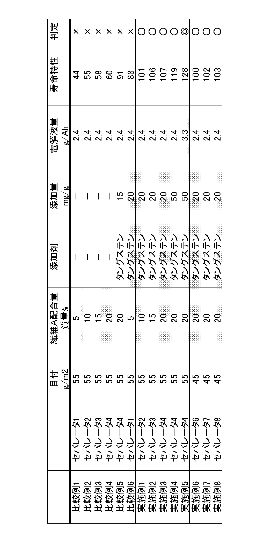
- Example 5 As the amount of electrolyte injected into the battery increases, the life characteristics are improved (Example 5). When the amount is higher than 3.3 g / Ah, the battery internal pressure during charging increases greatly. Since problems such as leakage occur, 3.3 g / Ah or less is desirable. The effect of the present invention was confirmed even when the separator basis weight was 45 g / m 2 (Examples 6 to 8).
Landscapes
- Chemical & Material Sciences (AREA)
- Chemical Kinetics & Catalysis (AREA)
- Electrochemistry (AREA)
- General Chemical & Material Sciences (AREA)
- Engineering & Computer Science (AREA)
- Manufacturing & Machinery (AREA)
- Battery Electrode And Active Subsutance (AREA)
- Secondary Cells (AREA)
- Cell Separators (AREA)
Description
本発明は、アイドリングストップ用途に適したアルカリ蓄電池及びそれを用いた蓄電池システムに関する。
近年、アイドリングストップ用鉛電池の負荷軽減(長寿命化)や、更なる燃費改善に向けた充電受入性改善を目的に、鉛蓄電池とアルカリ蓄電池との並列化が検討されている。
上記鉛電池と並列接続されるアルカリ蓄電池(例えば、特許文献1)においては、高出力(低抵抗)に加えて、エンジンルーム(雰囲気温度が60℃以上となる領域)に設置した場合においても耐え得るような高温耐久性能が求められる。
しかしながら、エンジンルームに設置した場合、アルカリ蓄電池は、正極極板が電解液中の水やカチオンを取り込んで極板が膨張する膨化が進行し、セパレータが保持する電解液量が減少し、セパレータドライアウトによる抵抗増大が発生する。このため、エンジンルーム設置した場合でも、所望の高温耐久性能を得るためにセパレータドライアウトの抑制が必要となる。
上記課題を解決するために、本発明では、酸化ニッケルを主正極活物質とするニッケル正極と水素吸蔵合金を負極活物質とする水素吸蔵合金負極とセパレータとからなる電極群を、アルカリ電解液とともに外装缶内に備えたアルカリ蓄電池であって、
前記アルカリ電解液は、タングステン化合物、モリブデン化合物、ニオブ化合物から選択された、いずれか1種以上の化合物が添加されており、前記タングステン化合物、モリブデン化合物、ニオブ化合物から選択されたいずれか1種以上の化合物の添加量は、電解液1g当り、20mg以上、50mg以下であって、前記セパレータは、繊維径の異なる繊維Aと繊維B(繊維径A<B)から成る不職布であって、目付が55g/m2以下であって、繊維Aの配合量が10質量%以上、20質量%以下であって、加圧保液率が5.1%以上であることを特徴とする。また、単位正極容量当たりのアルカリ電解液量は2.4g/Ah以上、3.3g/Ah以下であることが望ましい。
前記アルカリ電解液は、タングステン化合物、モリブデン化合物、ニオブ化合物から選択された、いずれか1種以上の化合物が添加されており、前記タングステン化合物、モリブデン化合物、ニオブ化合物から選択されたいずれか1種以上の化合物の添加量は、電解液1g当り、20mg以上、50mg以下であって、前記セパレータは、繊維径の異なる繊維Aと繊維B(繊維径A<B)から成る不職布であって、目付が55g/m2以下であって、繊維Aの配合量が10質量%以上、20質量%以下であって、加圧保液率が5.1%以上であることを特徴とする。また、単位正極容量当たりのアルカリ電解液量は2.4g/Ah以上、3.3g/Ah以下であることが望ましい。
上記構成であると、高出力(低抵抗)に加えて、エンジンルームに設置した場合においても耐え得るような高温耐久性能を有するアルカリ蓄電池及びそれを用いた蓄電池システムを提供することができる。
ついで、本発明の実施の形態を以下に詳細に説明するが、本発明はこれに限定されるものでなく、その要旨を変更しない範囲で適宜変更して実施することができる。
1.ニッケル正極
本発明のニッケル正極11は、基板となるニッケル焼結基板の多孔内に活物質が所定の充填量となるように充填されて形成されている。この場合、ニッケル焼結基板は以下のようにして作製されたものを用いている。例えば、ニッケル粉末に、増粘剤となるメチルセルロース(MC)と高分子中空微小球体(例えば、孔径が60μmのもの)と水とを混合、混練してニッケルスラリーを作製する。ついで、ニッケルめっき鋼板からなるパンチングメタルの両面にニッケルスラリーを塗着した後、還元性雰囲気中で1000℃で加熱して、増粘剤や高分子中空微小球体を消失させるとともにニッケル粉末同士を焼結することにより作製される。尚、得られた多孔性ニッケル基板を水銀圧入式ポロシメータ(ファイソンズ インスツルメンツ製 Pascal 140)で測定したところ、多孔度が85%であった。
本発明のニッケル正極11は、基板となるニッケル焼結基板の多孔内に活物質が所定の充填量となるように充填されて形成されている。この場合、ニッケル焼結基板は以下のようにして作製されたものを用いている。例えば、ニッケル粉末に、増粘剤となるメチルセルロース(MC)と高分子中空微小球体(例えば、孔径が60μmのもの)と水とを混合、混練してニッケルスラリーを作製する。ついで、ニッケルめっき鋼板からなるパンチングメタルの両面にニッケルスラリーを塗着した後、還元性雰囲気中で1000℃で加熱して、増粘剤や高分子中空微小球体を消失させるとともにニッケル粉末同士を焼結することにより作製される。尚、得られた多孔性ニッケル基板を水銀圧入式ポロシメータ(ファイソンズ インスツルメンツ製 Pascal 140)で測定したところ、多孔度が85%であった。
次いで、前記ニッケル焼結基板に、硝酸ニッケル、硝酸コバルト、硝酸亜鉛からなる含浸液に浸漬した後に、80℃(8mol/L)のアルカリ溶液(例えば水酸化ナトリウム水溶液)中に浸漬・反応させることで、水酸化ニッケル・水酸化コバルト・水酸化亜鉛に転換・細孔内で変化させ、その後水洗・乾燥した。本含浸サイクルを7回繰り返して、規定量の水酸化ニッケルを主体とする活物質を基板内に充填することで、焼結式正極を得た。
2.水素吸蔵合金負極
水素吸蔵合金負極12はパンチングメタルからなる負極芯体に水素吸蔵合金スラリーを塗着・形成している。この場合、水素吸蔵合金は、ネオジム(Nd)、マグネシウム(Mg)、ニッケル(Ni)、アルミニウム(Al)を所定のモル比の割合で混合し、この混合物を高周波誘導炉で溶解させ、これを溶融急冷して組成式がNd0.9Mg0.1Nia3.3Al0.2と表される水素吸蔵合金のインゴットを作製した。ついで、得られた水素吸蔵合金のインゴットについて、DSC(示差走査熱量計)を用いて融点(Tm)を測定した。その後、水素吸蔵合金のインゴットの融点(Tm)よりも30℃だけ低い温度(Ta=Tm-30℃)のアルゴンガス雰囲気で所定時間(この場合は10時間)の熱処理を行うことで均質化を行った。
水素吸蔵合金負極12はパンチングメタルからなる負極芯体に水素吸蔵合金スラリーを塗着・形成している。この場合、水素吸蔵合金は、ネオジム(Nd)、マグネシウム(Mg)、ニッケル(Ni)、アルミニウム(Al)を所定のモル比の割合で混合し、この混合物を高周波誘導炉で溶解させ、これを溶融急冷して組成式がNd0.9Mg0.1Nia3.3Al0.2と表される水素吸蔵合金のインゴットを作製した。ついで、得られた水素吸蔵合金のインゴットについて、DSC(示差走査熱量計)を用いて融点(Tm)を測定した。その後、水素吸蔵合金のインゴットの融点(Tm)よりも30℃だけ低い温度(Ta=Tm-30℃)のアルゴンガス雰囲気で所定時間(この場合は10時間)の熱処理を行うことで均質化を行った。
ついで、熱処理した水素吸蔵合金インゴットを不活性雰囲気中で機械的に粉砕し、篩分けにより400メッシュ~200メッシュの間に残る合金粉末を選別した。なお、レーザ回折・散乱式粒度分布測定装置により粒度分布を測定すると、質量積分50%にあたる平均粒径は25μmであった。これを水素吸蔵合金粉末とした。この後、得られた水素吸蔵合金粒子100質量部に対し、非水溶性高分子結着剤としてのSBR(スチレンブタジエンラテックス)を0.5質量部と、増粘剤としてCMC(カルボキシメチルセルロース)を0.3質量部と、適量の純水を加えて混練して、水素吸蔵合金スラリーを調製した。そして、得られた水素吸蔵合金スラリーをパンチングメタル(ニッケルメッキ鋼板製)からなる負極芯体の両面に塗着した後、100℃で乾燥させ、所定の充填密度になるように圧延した後、所定の寸法に裁断して水素吸蔵合金負極12を作製した。
3.セパレータ
セパレータ13は、単一構造を持つ極細繊維Aと複合構造を持つ芯鞘型融着繊維Bからなる不織布に、親水化処理を施したものである。上記繊維はポリオレフィン系合成樹脂からなり、例えばポリエチレン、ポリプロピレンなどの合成樹脂を用いることができる。不織布製法としては例えば乾式法、湿式法、スパンボンド法、メルトブロー法等によって作製されるが、緻密性の観点から湿式法が望ましい。
芯鞘型融着繊維はポリオレフィン系合成樹脂の鞘材で被覆されており、芯鞘型融着繊維自体が融着して不織布を構成できる。また、極細繊維の配合量を増やすことで平均繊維径が低減し、緻密な構造を持つ不織布が作製される。このようにして、表2に示すように、極細繊維Aの配合量が異なるセパレータを作製した。
4.電解液電解液は水酸化カリウム、水酸化ナトリウム、水酸化リチウムを所定のモル比、アルカリ濃度となるよう調整した混合水溶液にタングステン化合物、モリブデン化合物、ニオブ化合物から選択されたいずれか1種以上の化合物を添加した。この場合、表2に示すように、タングステン、モリブデン、ニオブが前記電解液1g当たり所定量となるよう添加した。
5.ニッケル-水素蓄電池
上述のようにして作製されたニッケル正極11と、水素吸蔵合金負極12とを用い、これらの間に、セパレータ13を介在させて渦巻状に巻回して渦巻状電極群を作製した。なお、このようにして作製された渦巻状電極群の上部にはニッケル正極11の芯体露出部11cが露出しており、その下部には水素吸蔵合金電極12の芯体露出部12cが露出している。ついで、得られた渦巻状電極群の下端面に露出する芯体露出部12cに負極集電体14を溶接するとともに、渦巻状電極群の上端面に露出するニッケル電極11の芯体露出部11cの上に正極集電体15を溶接して、電極体とした。
上述のようにして作製されたニッケル正極11と、水素吸蔵合金負極12とを用い、これらの間に、セパレータ13を介在させて渦巻状に巻回して渦巻状電極群を作製した。なお、このようにして作製された渦巻状電極群の上部にはニッケル正極11の芯体露出部11cが露出しており、その下部には水素吸蔵合金電極12の芯体露出部12cが露出している。ついで、得られた渦巻状電極群の下端面に露出する芯体露出部12cに負極集電体14を溶接するとともに、渦巻状電極群の上端面に露出するニッケル電極11の芯体露出部11cの上に正極集電体15を溶接して、電極体とした。
ついで、得られた電極体を鉄にニッケルメッキを施した有底筒状の外装缶(底面の外面は負極外部端子となる)17内に収納した後、負極集電体14を外装缶17の内底面に溶接した。一方、正極集電体15より延出する集電リード部15aを封口体18の底部に溶接した。なお、封口体18には正極キャップ18aが設けられていて、この正極キャップ18a内に所定の圧力になると変形する弁体18bとスプリング18cよりなる圧力弁(図示せず)が配置されている。
ついで、外装缶17の上部外周部に環状溝部17aを形成した後、アルカリ電解液を注液し、外装缶17の上部に形成された環状溝部17aの上に封口体18の外周部に装着された絶縁ガスケット19を載置した。この後、外装缶17の開口端縁17bをかしめることにより、電池容量が6.0Ahのニッケル-水素蓄電池10を作製した。
6.試験
(1)セパレータ加圧保液率 セパレータを直径30mmに裁断し、温度20℃、相対湿度65%で水分平衡に至らせた後、質量W1を測定した。次に比重1.3(20℃)の水酸化カリウムに1時間浸漬した後、このセパレータを上下から直径30mmのろ紙で挟み込み、加圧ポンプにより60kg/cm2の圧力を30秒間加圧した。加圧後のセパレータ質量W2を測定し、下記式にて加圧保液率を算出した。
加圧保液率=(W2-W1)/W1×100
(1)セパレータ加圧保液率 セパレータを直径30mmに裁断し、温度20℃、相対湿度65%で水分平衡に至らせた後、質量W1を測定した。次に比重1.3(20℃)の水酸化カリウムに1時間浸漬した後、このセパレータを上下から直径30mmのろ紙で挟み込み、加圧ポンプにより60kg/cm2の圧力を30秒間加圧した。加圧後のセパレータ質量W2を測定し、下記式にて加圧保液率を算出した。
加圧保液率=(W2-W1)/W1×100
(2)寿命特性 以下条件での充放電サイクルにより寿命特性を評価した。
環境温度:60℃±3℃ (雰囲気温度が60℃以上となるエンジンルームに対応して設定)
第1放電:放電電流20A±1Aで59.0秒±0.2秒
第2放電:放電電流150A±1Aで1.0秒±0.2秒
充電 :充電電圧1.40V±0.01V(制限電流100.0A±0.5A)で60.0秒±0.3秒充電
第2放電において、最終電圧が0.9V未満を確認した時のサイクル数を寿命特性とする。
環境温度:60℃±3℃ (雰囲気温度が60℃以上となるエンジンルームに対応して設定)
第1放電:放電電流20A±1Aで59.0秒±0.2秒
第2放電:放電電流150A±1Aで1.0秒±0.2秒
充電 :充電電圧1.40V±0.01V(制限電流100.0A±0.5A)で60.0秒±0.3秒充電
第2放電において、最終電圧が0.9V未満を確認した時のサイクル数を寿命特性とする。
5.試験結果
(1)セパレータ加圧保液率
セパレータ加圧保液率の測定結果を表1に示す。極細繊維Aの配合量を増やすことで加圧保液率が増大することを確認した。これは、極細繊維Aの配合量を増やすことで、平均繊維径が低減し、緻密な構造を持つとともに、耐圧縮性が増大するためと考えられる。一方、極細繊維Aの配合量が10質量%未満の領域では、加圧保液率が大きく低下した。比表面積が低下するため、十分な液保持性が得られないためと考えられる。

(1)セパレータ加圧保液率
セパレータ加圧保液率の測定結果を表1に示す。極細繊維Aの配合量を増やすことで加圧保液率が増大することを確認した。これは、極細繊維Aの配合量を増やすことで、平均繊維径が低減し、緻密な構造を持つとともに、耐圧縮性が増大するためと考えられる。一方、極細繊維Aの配合量が10質量%未満の領域では、加圧保液率が大きく低下した。比表面積が低下するため、十分な液保持性が得られないためと考えられる。
(2)寿命特性
ニッケル水素電池の寿命特性評価結果を表2にまとめる。比較例1から4に示すように、セパレータの極細繊維Aの配合量を増やすことで、寿命特性の向上が見られたが、所望する耐久性に対して不十分であった。耐久後の電池を解体解析した結果、セパレータの保持液量が大きく低下していたことから、ドライアウト現象により電池抵抗が増大したものと考えられる。
ニッケル水素電池の寿命特性評価結果を表2にまとめる。比較例1から4に示すように、セパレータの極細繊維Aの配合量を増やすことで、寿命特性の向上が見られたが、所望する耐久性に対して不十分であった。耐久後の電池を解体解析した結果、セパレータの保持液量が大きく低下していたことから、ドライアウト現象により電池抵抗が増大したものと考えられる。
一方、実施例1から3に示すように、電解液中にタングステンを添加した場合、大幅な寿命特性の改善効果を確認した。タングステン添加により高温充電効率が向上し、正極極板の膨化が抑制されるためと考えられる。比較例6に対して、加圧保液率の高いセパレータとタングステン添加を組み合わせることで(実施例1から3)、寿命特性の改善効果が顕著に発現する。加えて、タングステン添加量を増大させることで、さらに寿命特性が向上することを確認した(実施例4)。
なお、タングステン添加量は電解液1g当たり20mg未満では、十分な寿命改善効果が得られなかった(比較例5)。また、50mgよりも多く添加すると、液抵抗の増大により電池出力特性が低下することから、添加量は電解液1g当たり20mg以上、50mg以下が望ましい。
なお、電池内に注液される電解液量が多いほど、寿命特性が改善されるが(実施例5)、3.3g/Ahより多いと、充電時の電池内圧上昇が大きく、場合によっては漏液するといった課題が発生するため、3.3g/Ah以下が望ましい。
また、本発明の効果はセパレータ目付が45g/m2であっても同様の効果を確認した(実施例6から8)。
また、本発明の効果はセパレータ目付が45g/m2であっても同様の効果を確認した(実施例6から8)。
11…ニッケル電極、11c…芯体露出部、12…水素吸蔵合金電極、12c…芯体露出部、13…セパレータ、14…負極集電体、15…正極集電体、15a…集電リード部、17…外装缶、17a…環状溝部、17b…開口端縁、18…封口体、18a…正極キャップ、18b…弁板、18c…スプリング、19…絶縁ガスケット
Claims (3)
- 水酸化ニッケルを主正極活物質とするニッケル正極と水素吸蔵合金を負極活物質とする水素吸蔵合金負極とセパレータとからなる電極群を、アルカリ電解液とともに外装缶内に備えたアルカリ蓄電池であって、
前記アルカリ電解液は、タングステン化合物、モリブデン化合物、ニオブ化合物から選択された、いずれか1種以上の化合物が添加されており、前記タングステン化合物、モリブデン化合物、ニオブ化合物から選択されたいずれか1種以上の化合物の添加量は、電解液1g当り、20mg以上、50mg以下であり、
前記セパレータは、繊維径の異なる繊維Aと繊維B(繊維径A<B)から成る不職布であって、目付が55g/m2以下、繊維Aの配合量が10質量%以上、20質量%以下であり、かつ加圧保液率が5.1%以上であることを特徴とするアルカリ蓄電池。 - 前記アルカリ電解液は単位正極容量当たりのアルカリ電解液量が2.4g/Ah以上、3.3g/Ah以下であることを特徴とする請求項1に記載のアルカリ蓄電池。
- 請求項1又は2に記載のアルカリ蓄電池を用いた蓄電池システム。
Priority Applications (2)
| Application Number | Priority Date | Filing Date | Title |
|---|---|---|---|
| JP2014538172A JPWO2014050074A1 (ja) | 2012-09-25 | 2013-09-24 | アルカリ蓄電池及びそれを用いた蓄電池システム。 |
| CN201380043783.5A CN104584314A (zh) | 2012-09-25 | 2013-09-24 | 碱性蓄电池以及使用该碱性蓄电池的蓄电池系统 |
Applications Claiming Priority (2)
| Application Number | Priority Date | Filing Date | Title |
|---|---|---|---|
| JP2012210313 | 2012-09-25 | ||
| JP2012-210313 | 2012-09-25 |
Publications (1)
| Publication Number | Publication Date |
|---|---|
| WO2014050074A1 true WO2014050074A1 (ja) | 2014-04-03 |
Family
ID=50387512
Family Applications (1)
| Application Number | Title | Priority Date | Filing Date |
|---|---|---|---|
| PCT/JP2013/005629 Ceased WO2014050074A1 (ja) | 2012-09-25 | 2013-09-24 | アルカリ蓄電池及びそれを用いた蓄電池システム。 |
Country Status (3)
| Country | Link |
|---|---|
| JP (1) | JPWO2014050074A1 (ja) |
| CN (1) | CN104584314A (ja) |
| WO (1) | WO2014050074A1 (ja) |
Citations (8)
| Publication number | Priority date | Publication date | Assignee | Title |
|---|---|---|---|---|
| JPS61156639A (ja) * | 1984-12-27 | 1986-07-16 | Matsushita Electric Ind Co Ltd | 密閉形アルカリ蓄電池 |
| JPH09283174A (ja) * | 1996-04-18 | 1997-10-31 | Matsushita Electric Ind Co Ltd | アルカリ蓄電池 |
| JP2001217000A (ja) * | 1999-02-26 | 2001-08-10 | Toshiba Battery Co Ltd | ニッケル・水素二次電池 |
| JP2003234097A (ja) * | 2002-02-08 | 2003-08-22 | Japan Vilene Co Ltd | 電池用セパレータ及び電池 |
| JP2003239170A (ja) * | 2002-02-08 | 2003-08-27 | Japan Vilene Co Ltd | 不織布及びこれを用いた電池 |
| JP2004281289A (ja) * | 2003-03-18 | 2004-10-07 | Sanyo Electric Co Ltd | アルカリ蓄電池 |
| WO2012128071A1 (ja) * | 2011-03-23 | 2012-09-27 | 三洋電機株式会社 | 非水電解質二次電池 |
| JP2013178883A (ja) * | 2012-02-28 | 2013-09-09 | Sanyo Electric Co Ltd | アルカリ蓄電池及びアルカリ蓄電池システム |
Family Cites Families (7)
| Publication number | Priority date | Publication date | Assignee | Title |
|---|---|---|---|---|
| JP2962326B1 (ja) * | 1997-12-26 | 1999-10-12 | 松下電器産業株式会社 | バックアップ電源用ニッケル−水素蓄電池 |
| JP4031620B2 (ja) * | 2001-04-09 | 2008-01-09 | 松下電器産業株式会社 | ニッケル水素蓄電池およびその使用方法 |
| JP2003249222A (ja) * | 2001-12-12 | 2003-09-05 | Sanyo Electric Co Ltd | ニッケル・水素蓄電池 |
| JP4639620B2 (ja) * | 2004-03-29 | 2011-02-23 | トヨタ自動車株式会社 | アルカリ蓄電池 |
| JP5046539B2 (ja) * | 2006-03-24 | 2012-10-10 | 三洋電機株式会社 | ニッケル水素蓄電池 |
| JP5173320B2 (ja) * | 2007-08-29 | 2013-04-03 | 三洋電機株式会社 | 水素吸蔵合金電極およびこの水素吸蔵合金電極を用いたアルカリ蓄電池 |
| CN101950818A (zh) * | 2010-09-20 | 2011-01-19 | 四川宝生新能源电池有限公司 | 高温镍氢电池 |
-
2013
- 2013-09-24 WO PCT/JP2013/005629 patent/WO2014050074A1/ja not_active Ceased
- 2013-09-24 JP JP2014538172A patent/JPWO2014050074A1/ja active Pending
- 2013-09-24 CN CN201380043783.5A patent/CN104584314A/zh active Pending
Patent Citations (8)
| Publication number | Priority date | Publication date | Assignee | Title |
|---|---|---|---|---|
| JPS61156639A (ja) * | 1984-12-27 | 1986-07-16 | Matsushita Electric Ind Co Ltd | 密閉形アルカリ蓄電池 |
| JPH09283174A (ja) * | 1996-04-18 | 1997-10-31 | Matsushita Electric Ind Co Ltd | アルカリ蓄電池 |
| JP2001217000A (ja) * | 1999-02-26 | 2001-08-10 | Toshiba Battery Co Ltd | ニッケル・水素二次電池 |
| JP2003234097A (ja) * | 2002-02-08 | 2003-08-22 | Japan Vilene Co Ltd | 電池用セパレータ及び電池 |
| JP2003239170A (ja) * | 2002-02-08 | 2003-08-27 | Japan Vilene Co Ltd | 不織布及びこれを用いた電池 |
| JP2004281289A (ja) * | 2003-03-18 | 2004-10-07 | Sanyo Electric Co Ltd | アルカリ蓄電池 |
| WO2012128071A1 (ja) * | 2011-03-23 | 2012-09-27 | 三洋電機株式会社 | 非水電解質二次電池 |
| JP2013178883A (ja) * | 2012-02-28 | 2013-09-09 | Sanyo Electric Co Ltd | アルカリ蓄電池及びアルカリ蓄電池システム |
Also Published As
| Publication number | Publication date |
|---|---|
| CN104584314A (zh) | 2015-04-29 |
| JPWO2014050074A1 (ja) | 2016-08-22 |
Similar Documents
| Publication | Publication Date | Title |
|---|---|---|
| JP2575840B2 (ja) | 水素吸蔵合金電極の乾式製造方法 | |
| JP5361712B2 (ja) | 新規なアルカリ蓄電池用銀正極 | |
| JP5743780B2 (ja) | 円筒型ニッケル−水素蓄電池 | |
| CN101931078B (zh) | 碱性蓄电池用贮氢合金及其制造方法 | |
| US20090087745A1 (en) | Alkaline storage battery system | |
| JP2011233423A (ja) | アルカリ蓄電池 | |
| JP2009087632A (ja) | アルカリ蓄電池システム | |
| JP2013114888A (ja) | アルカリ蓄電及びこのアルカリ蓄電池を用いたアルカリ蓄電池システム | |
| JP5322392B2 (ja) | 水素吸蔵合金電極およびその製造方法ならびにアルカリ蓄電池 | |
| JP5849768B2 (ja) | アルカリ蓄電池及びアルカリ蓄電池システム | |
| JP5868669B2 (ja) | アルカリ蓄電池 | |
| JP5717125B2 (ja) | アルカリ蓄電池 | |
| JP2012238565A (ja) | アルカリ蓄電池 | |
| JP6024295B2 (ja) | アルカリ蓄電池 | |
| JPWO2014050074A1 (ja) | アルカリ蓄電池及びそれを用いた蓄電池システム。 | |
| JPWO2014050075A1 (ja) | 蓄電池システム。 | |
| JP2022041906A (ja) | 水素吸蔵合金、この水素吸蔵合金を含む負極及びこの負極を含むニッケル水素二次電池 | |
| JPH0763006B2 (ja) | 水素吸蔵電極の製造方法 | |
| JP2004281289A (ja) | アルカリ蓄電池 | |
| JP3182790B2 (ja) | 水素吸蔵合金電極およびその製造法 | |
| JP5493833B2 (ja) | アルカリ蓄電池及びその製造方法 | |
| CN115411265B (zh) | 储氢合金负极以及包含储氢合金负极的镍氢二次电池 | |
| JP2013211122A (ja) | アルカリ蓄電池 | |
| JP5752487B2 (ja) | アルカリ蓄電池およびアルカリ蓄電池システム | |
| JP3851022B2 (ja) | アルカリ蓄電池用ニッケル極及びアルカリ蓄電池 |
Legal Events
| Date | Code | Title | Description |
|---|---|---|---|
| 121 | Ep: the epo has been informed by wipo that ep was designated in this application |
Ref document number: 13842017 Country of ref document: EP Kind code of ref document: A1 |
|
| ENP | Entry into the national phase |
Ref document number: 2014538172 Country of ref document: JP Kind code of ref document: A |
|
| NENP | Non-entry into the national phase |
Ref country code: DE |
|
| 122 | Ep: pct application non-entry in european phase |
Ref document number: 13842017 Country of ref document: EP Kind code of ref document: A1 |