WO2014049847A1 - コイル、回転電機、及びリニアモータ - Google Patents
コイル、回転電機、及びリニアモータ Download PDFInfo
- Publication number
- WO2014049847A1 WO2014049847A1 PCT/JP2012/075156 JP2012075156W WO2014049847A1 WO 2014049847 A1 WO2014049847 A1 WO 2014049847A1 JP 2012075156 W JP2012075156 W JP 2012075156W WO 2014049847 A1 WO2014049847 A1 WO 2014049847A1
- Authority
- WO
- WIPO (PCT)
- Prior art keywords
- winding
- conductor
- coil
- along
- portions
- Prior art date
- Legal status (The legal status is an assumption and is not a legal conclusion. Google has not performed a legal analysis and makes no representation as to the accuracy of the status listed.)
- Ceased
Links
Images


Classifications
-
- H—ELECTRICITY
- H01—ELECTRIC ELEMENTS
- H01F—MAGNETS; INDUCTANCES; TRANSFORMERS; SELECTION OF MATERIALS FOR THEIR MAGNETIC PROPERTIES
- H01F5/00—Coils
-
- H—ELECTRICITY
- H01—ELECTRIC ELEMENTS
- H01F—MAGNETS; INDUCTANCES; TRANSFORMERS; SELECTION OF MATERIALS FOR THEIR MAGNETIC PROPERTIES
- H01F5/00—Coils
- H01F5/02—Coils wound on non-magnetic supports, e.g. formers
-
- H—ELECTRICITY
- H01—ELECTRIC ELEMENTS
- H01F—MAGNETS; INDUCTANCES; TRANSFORMERS; SELECTION OF MATERIALS FOR THEIR MAGNETIC PROPERTIES
- H01F5/00—Coils
- H01F5/04—Arrangements of electric connections to coils, e.g. leads
-
- H—ELECTRICITY
- H02—GENERATION; CONVERSION OR DISTRIBUTION OF ELECTRIC POWER
- H02K—DYNAMO-ELECTRIC MACHINES
- H02K15/00—Processes or apparatus specially adapted for manufacturing, assembling, maintaining or repairing of dynamo-electric machines
- H02K15/04—Processes or apparatus specially adapted for manufacturing, assembling, maintaining or repairing of dynamo-electric machines of windings prior to their mounting into the machines
- H02K15/043—Processes or apparatus specially adapted for manufacturing, assembling, maintaining or repairing of dynamo-electric machines of windings prior to their mounting into the machines winding flat conductive wires or sheets
- H02K15/0431—Concentrated windings
-
- H—ELECTRICITY
- H02—GENERATION; CONVERSION OR DISTRIBUTION OF ELECTRIC POWER
- H02K—DYNAMO-ELECTRIC MACHINES
- H02K3/00—Details of windings
- H02K3/04—Windings characterised by the conductor shape, form or construction, e.g. with bar conductors
- H02K3/12—Windings characterised by the conductor shape, form or construction, e.g. with bar conductors arranged in slots
-
- H—ELECTRICITY
- H02—GENERATION; CONVERSION OR DISTRIBUTION OF ELECTRIC POWER
- H02K—DYNAMO-ELECTRIC MACHINES
- H02K3/00—Details of windings
- H02K3/04—Windings characterised by the conductor shape, form or construction, e.g. with bar conductors
- H02K3/18—Windings for salient poles
-
- H—ELECTRICITY
- H02—GENERATION; CONVERSION OR DISTRIBUTION OF ELECTRIC POWER
- H02K—DYNAMO-ELECTRIC MACHINES
- H02K3/00—Details of windings
- H02K3/04—Windings characterised by the conductor shape, form or construction, e.g. with bar conductors
- H02K3/28—Layout of windings or of connections between windings
-
- H—ELECTRICITY
- H02—GENERATION; CONVERSION OR DISTRIBUTION OF ELECTRIC POWER
- H02K—DYNAMO-ELECTRIC MACHINES
- H02K41/00—Propulsion systems in which a rigid body is moved along a path due to dynamo-electric interaction between the body and a magnetic field travelling along the path
- H02K41/02—Linear motors; Sectional motors
-
- H—ELECTRICITY
- H02—GENERATION; CONVERSION OR DISTRIBUTION OF ELECTRIC POWER
- H02K—DYNAMO-ELECTRIC MACHINES
- H02K41/00—Propulsion systems in which a rigid body is moved along a path due to dynamo-electric interaction between the body and a magnetic field travelling along the path
- H02K41/02—Linear motors; Sectional motors
- H02K41/03—Synchronous motors; Motors moving step by step; Reluctance motors
- H02K41/031—Synchronous motors; Motors moving step by step; Reluctance motors of the permanent magnet type
-
- H—ELECTRICITY
- H02—GENERATION; CONVERSION OR DISTRIBUTION OF ELECTRIC POWER
- H02K—DYNAMO-ELECTRIC MACHINES
- H02K9/00—Arrangements for cooling or ventilating
- H02K9/10—Arrangements for cooling or ventilating by gaseous cooling medium flowing in closed circuit, a part of which is external to the machine casing
-
- H—ELECTRICITY
- H01—ELECTRIC ELEMENTS
- H01F—MAGNETS; INDUCTANCES; TRANSFORMERS; SELECTION OF MATERIALS FOR THEIR MAGNETIC PROPERTIES
- H01F41/00—Apparatus or processes specially adapted for manufacturing or assembling magnets, inductances or transformers; Apparatus or processes specially adapted for manufacturing materials characterised by their magnetic properties
- H01F41/02—Apparatus or processes specially adapted for manufacturing or assembling magnets, inductances or transformers; Apparatus or processes specially adapted for manufacturing materials characterised by their magnetic properties for manufacturing cores, coils, or magnets
- H01F41/04—Apparatus or processes specially adapted for manufacturing or assembling magnets, inductances or transformers; Apparatus or processes specially adapted for manufacturing materials characterised by their magnetic properties for manufacturing cores, coils, or magnets for manufacturing coils
- H01F41/06—Coil winding
- H01F41/071—Winding coils of special form
-
- H—ELECTRICITY
- H02—GENERATION; CONVERSION OR DISTRIBUTION OF ELECTRIC POWER
- H02K—DYNAMO-ELECTRIC MACHINES
- H02K3/00—Details of windings
- H02K3/46—Fastening of windings on the stator or rotor structure
- H02K3/52—Fastening salient pole windings or connections thereto
- H02K3/521—Fastening salient pole windings or connections thereto applicable to stators only
- H02K3/524—Fastening salient pole windings or connections thereto applicable to stators only for U-shaped, E-shaped or similarly shaped cores
-
- H—ELECTRICITY
- H02—GENERATION; CONVERSION OR DISTRIBUTION OF ELECTRIC POWER
- H02K—DYNAMO-ELECTRIC MACHINES
- H02K5/00—Casings; Enclosures; Supports
- H02K5/04—Casings or enclosures characterised by the shape, form or construction thereof
- H02K5/20—Casings or enclosures characterised by the shape, form or construction thereof with channels or ducts for flow of cooling medium
- H02K5/203—Casings or enclosures characterised by the shape, form or construction thereof with channels or ducts for flow of cooling medium specially adapted for liquids, e.g. cooling jackets
-
- H—ELECTRICITY
- H02—GENERATION; CONVERSION OR DISTRIBUTION OF ELECTRIC POWER
- H02K—DYNAMO-ELECTRIC MACHINES
- H02K9/00—Arrangements for cooling or ventilating
- H02K9/22—Arrangements for cooling or ventilating by solid heat conducting material embedded in, or arranged in contact with, the stator or rotor, e.g. heat bridges
- H02K9/227—Heat sinks
Definitions
- the disclosed embodiment relates to a coil, a rotating electrical machine, and a linear motor.
- Patent Document 1 describes a rectangular coil having four sides that are linearly wound by winding a conductor (flat wire) having a rectangular cross section. For example, this coil is used by being mounted in a slot of a stator of a rotating electric machine.
- the surface of the coil may not be smooth due to, for example, a sequentially wound conductor riding on another conductor.
- the coil when the coil is mounted on a rotating electric machine or the like and used, it is difficult to sufficiently adhere the coil to the mounting portion. As a result, it becomes difficult to dissipate heat generated from the coil from the close contact portion to the mounting portion and efficiently cool it.
- the present invention has been made in view of such problems, and an object of the present invention is to provide a coil capable of efficiently radiating and cooling generated heat, and a rotating electric machine and a linear motor using the coil.
- a conductor is wound around a predetermined direction in a circle from a start point to an end point to generate one winding portion, and then the conductor is moved in the rotation direction.
- the conductor is moved in the rotation direction.
- the outer shape of the rectangle is substantially rectangular or substantially positive with the four corners being substantially arc-shaped.
- the one winding part has a position in the first direction that is the same pitch as the starting point or a half pitch that is half of the one pitch.
- the at least one parallel portion extending in the circumferential direction so as to be shifted and the two parallel portions whose positions in the first direction are shifted from each other by the half pitch are connected to each other, or the first At least one connecting portion that connects the end point located at the end of one of the parallel portions whose positions in the direction are shifted from each other by the half pitch and the start point of the other winding portion, and the connection A coil in which a portion is disposed at a portion corresponding to one of the four corners is applied.
- a rotor having a rotating shaft, a load-side bracket and an anti-load side that rotatably support the rotating shaft on a load side and an anti-load side, respectively.
- a bracket and a substantially cylindrical stator that is provided so as to surround the outer peripheral side of the rotor and is fixed to the load-side bracket and the anti-load-side bracket, respectively,
- a rotating electrical machine comprising: a stator core having a plurality of slots arranged in a cylindrical circumferential direction; and a plurality of coils inserted into the plurality of slots, each of the plurality of coils having a predetermined conductor.
- the conductor After winding one turn from the start point to the end point substantially along the winding direction to generate one winding portion, the conductor is shifted by one pitch in the first direction orthogonal to the winding direction, and further made a round along the winding direction.
- a conductor cylinder part formed of a plurality of winding parts arranged along the first direction is formed, After forming one said conductor cylinder part, the other conductor cylinder part adjacent to the 2nd direction orthogonal to the said 1st direction of the said one conductor cylinder part is formed in order along the said 2nd direction.
- a plurality of conductor tube portions, and the conductor has an outer shape of the coil as viewed from the first direction, which is a substantially rectangular shape or a substantially square shape having substantially arc shapes at the four corners,
- the one winding portion is arranged so that the position in the first direction is shifted from the start point by a half pitch that is the same pitch as the start point or a half of the one pitch.
- At least one parallel portion extending in a direction, and the first The two parallel portions whose positions in the direction are shifted from each other by the half pitch, or the end points located at the ends of the one parallel portion whose positions in the first direction are shifted from each other by the half pitch.
- at least one connecting portion that connects the starting point of the another winding portion, and the connecting portion is disposed at a portion corresponding to one of the four corner portions.
- a rotating electrical machine is applied.
- An armature including an armature base and a plurality of coils attached to the armature base, wherein one of the field and the armature is a stator and the other is a mover.
- a linear motor that causes the mover to travel along a predetermined traveling direction, wherein each of the plurality of coils is configured by winding a conductor around a predetermined winding direction from a start point to an end point, and a single winding portion.
- the conductor is shifted by one pitch in the first direction orthogonal to the winding direction, and further rotated once along the winding direction, and another winding adjacent to the first direction of the one winding part.
- the turn part sequentially, After forming a conductor tube portion composed of a plurality of winding portions arranged along the first direction and forming one of the conductor tube portions, the one conductor tube portion is orthogonal to the first direction.
- a plurality of conductor tube portions are arranged along the second direction by sequentially forming another conductor tube portion adjacent in the second direction, and the conductor is viewed from the first direction.
- the outer shape of the coil is wound so as to be a substantially rectangular shape or a substantially square shape with the four corners being substantially arc-shaped, and the position of the one winding portion in the first direction is the same as the starting point.
- the linear motor is characterized in that the connecting portion is disposed at a portion corresponding to one of the four corners.
- the generated heat can be efficiently radiated and cooled.
- FIG. 2 is a longitudinal sectional view taken along the line XX in FIG. It is explanatory drawing for demonstrating the winding process of the coil with which the linear motor was equipped, the cross-sectional view by a YY cross section, and the top view of the jig
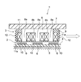
- the linear motor 1 of this embodiment is provided with the field 2 which comprises a stator, and the armature 3 which comprises a mover.
- the field 2 includes a field yoke 5 installed on the yoke mounting portion 4 and a plurality of permanent magnets 6 disposed on the field yoke 5.
- the plurality of permanent magnets 6 are arranged so as to be adjacent to each other at an equal pitch along the longitudinal direction of the field yoke 5 (moving direction of the armature 3), and alternately have different polarities.
- the armature 3 is disposed opposite to the permanent magnet 6 of the field 2 in parallel via a magnetic gap.
- the armature 3 includes an armature base 7, a core 8, a bracket 9 attached to the armature base 7 so as to surround the core 8, and a plurality (three in this example) of coils 10 of three. And.
- the core 8 is attached to the surface of the armature base 7 facing the field 2 and is constituted by a laminated body obtained by punching electromagnetic steel sheets into a comb shape.
- the core 8 has a plurality (three in this example) of teeth 8 a protruding in the direction of the field 2.
- the teeth 8a are provided at equal intervals in the longitudinal direction of the armature 3 (left and right direction in FIG. 2).
- each coil 10 is housed and disposed so as to be in close contact with the bracket 9 while being attached to the core 8.
- each coil 10 has a slot 8b formed between adjacent teeth 8a while a hole 18 (see FIG. 5C described later) on the inner peripheral side of the coil 10 is fitted into the teeth 8a. Is housed.
- an outer peripheral portion (in detail, a straight portion 17a or 17b described later) of the portion of the coil 10 exposed from the core 8 is attached to the bracket 9 in a state of being in contact with the inner surface 11a of the concave portion 11 of the bracket 9.
- the bracket 9 has cooling fins 12 formed on the outer peripheral surface.
- a connecting portion 14 is provided between the coil 10 and the armature base 7 at one end in the width direction of the armature 3 (left side in FIG. 1).
- each coil 10 includes a first protrusion 15a and a second protrusion 15b of the conductor 15 protruding from the coil 10 on the winding start side and winding end side of the conductor 15 (see FIG. 3 described later). Is formed.
- the connection part 14 connects the 1st protrusion part 15a and the 2nd protrusion part 15b of each coil 10, and connects to the external power supply which is not shown in figure.
- each coil 10 is supplied with a three-phase alternating current of a corresponding phase of the U phase, the V phase, and the W phase from an external power source through the connection portion 14 and the first and second projecting portions 15a and 15b.
- a magnetic field is generated in the coil 10.
- a repulsive force and an attractive force act between the coil 10 and the permanent magnet 6 of the field 2, and a thrust is generated in the armature 3.
- the armature 3 travels along the traveling direction indicated by the white arrow in the drawing.
- a feature of the present embodiment is a winding method of a conductor 15 (see FIG. 3 and the like described later) for smoothing the surface of the coil 10.
- the coil 10 generally includes a first step of winding the conductor 15 in the circumferential direction, and a first step of pressure-forming a predetermined portion of an unformed coil 17 (see FIG. 4 described later) obtained by the first step. It is manufactured by two steps.
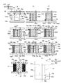
- FIGS. 3A to 3K and FIGS. 4A to 4D the vertical direction (height direction), the front-rear direction, and the left-right direction are shown in FIGS. 3 (a) to 3 (j), FIG. 3 (k), and FIGS. 4 (a) to 4 (d). This corresponds to the direction of the arrow shown as appropriate in the figure.
- the conductor 15 is repeatedly wound in the circumferential direction along the substantially horizontal direction, and a plurality of conductor tube portions 16 (described later) stacked in the radial direction are formed.
- the conductor 15 is a round copper wire of a bond wire coated with a resin having insulation performance and heat fusion performance.
- a winding jig 30 arranged in a predetermined posture is used.
- the winding jig 30 includes a substantially rectangular parallelepiped core pin portion 31 having a substantially rectangular horizontal cross section. This core pin portion 31 can be divided into two vertically by a suitable fitting structure (not shown) at approximately half the height direction (see dotted line h in FIGS. 3A and 3J).
- An upper spacer portion 32 a is integrally provided at the upper end portion of the upper half of the divided core pin portion 31, and a lower spacer portion 32 b is integrally provided at the lower end portion of the lower half of the core pin portion 31.
- the upper spacer portion 32a is provided with through holes 33a and 33b through which the conductor 15 passes.
- the through holes 33a and 33b are positioned close to one corner (the first corner 31a on the right front side in this example) of the four corners 31a, 31b, 31c, and 31d of the core pin portion 31, and the diameter thereof. It is provided at each of the direction outer side positions.
- the conductor 15 is extended upward by a predetermined amount from the through hole 33a of the upper spacer portion 32a to form a first protruding portion 15a.
- a portion of the conductor 15 that follows the first protruding portion 15a is defined as a first corner portion 31a on the right front side of the core pin portion 31 with the first corner portion 31s as a circulation start point 15s.
- Round around the core pin portion 31 as follows: portion 31a ⁇ second corner portion 31b on the right rear side ⁇ third corner portion 31c on the left rear side ⁇ fourth corner portion 31d on the left front side ⁇ first corner portion 31a on the right front side Wind.
- the conductor 15 is placed on the first corner 31a on the right front side from the start point 15s and the second corner on the right rear side. Extending in the horizontal direction (corresponding to the circumferential direction) toward the portion 31b (extension portion 15A1-1), and then the conductor 15 is directed from the second corner portion 31b to the third corner portion 31c on the left rear side. Then, the conductor 15 is extended in the horizontal direction from the third corner 31c toward the fourth corner 31d on the left front side (extension portion 15A1-2). 15A1-3). As a result, the first parallel portion 15A1 is formed which includes the three extending portions 15A1-1, 15A-2, and 15A-3 at the same pitch with respect to the start point 15s (that is, at the same vertical position as the start point s). The
- the winding pitch of the conductor 15 is half the pitch (hereinafter, simply referred to as “half pitch” as appropriate) with respect to the first parallel portion 15A1. )
- a first connection portion 15B1 (so-called stepped-up portion) that connects the first parallel portion 15A1 and a second parallel portion 15A2 described later is formed.
- the conductor 15 is extended in the horizontal direction toward the end point 15e located at the first corner portion 31a, thereby forming the second parallel portion 15A2 which is located at a half pitch downward with respect to the start point 15s. .
- the conductor 15 that has reached the first corner portion 31a is moved in a direction oblique to the horizontal direction so as to be shifted downward by a half pitch with respect to the second parallel portion 15A2.
- the end point 15e positioned at the end of the second parallel portion 15A2 of the first winding portion 15A is set to the start point 15s of the second winding portion 15A that starts winding from the first corner portion 31a as described above.
- a second connection portion 15B2 (so-called stepped-up portion) that is connected to is formed.
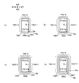
- the first winding portion 15A including the first parallel portion 15A1, the first connection portion 15B1, the second parallel portion 15A2, and the second connection portion 15B2 is completed (see FIG. 4A).
- the second winding portion 15A is formed. That is, the second corner 31b ⁇ the third corner 31c ⁇ the fourth corner from the start point 15s which is located one pitch downward from the start point 15s of the first winding part 15A in the first corner 31a.
- a conductor 15 is extended in the horizontal direction with 31d to form a first parallel portion 15A1 composed of the extension portions 15A1-1, 15A1-2, and 15A1-3.
- the second parallel portion 15A2 extending in the horizontal direction toward the end point 15e located at the first corner portion 31a via the first connection portion 15B1 extending in the oblique direction at the fourth corner portion 31d.
- the second parallel portion 15A2 and the next third winding portion 15A are connected by a second connection portion 15B2 extending in an oblique direction.
- the second winding portion 15A including the first parallel portion 15A1, the first connection portion 15B1, the second parallel portion 15A2, and the second connection portion 15B2 is completed.
- the first parallel part 15A1, the first connection part 15B1, the second parallel part 15A2, and the second connection part 15B2 of the second winding part 15A are the first parallel part of the first winding part 15A.
- Each of the first connecting portion 15B1, the second connecting portion 15B2, the second connecting portion 15B2, and the second connecting portion 15B2 is shifted by one pitch downward.
- the conductor 15 is shifted one pitch downward along the up-down direction and is made to make one turn along the circumferential direction so that the third winding portion 15A, the fourth winding portion 15A,... Then, another winding portion 15A adjacent to the lower side is sequentially generated (see FIG. 3B). In this way, the winding portion 15A is sequentially generated between the upper spacer portion 32a and the lower spacer portion 32b of the core pin portion 31 up to the lowermost winding portion 15A reaching the lower spacer portion 32b.
- the first parallel portion 15A1 including the extending portions 15A1-1, 15A1-2, and 15A1-3 is the same as the winding portion 15A in the other stages described above, but the first connection The part 15B1 ′, the second parallel part 15A2, and the second connection part 15B2 ′ are different from the winding part 15A in the other stages.
- the position in the vertical direction is the same (same pitch) as that of the first parallel portion 15A1, and 1 on the outer side along the radial direction (corresponding to the second direction) perpendicular to the vertical direction.
- the conductor 15 is extended while expanding in the horizontal direction so as to be shifted by a small pitch (a value slightly smaller than the value of the wire diameter of the conductor 15).
- a first connection portion 15B1 ′ (so-called stepped-up portion) that connects the first parallel portion 15A1 and a second parallel portion 15A2 described later is formed.
- the conductor 15 is extended in the horizontal direction toward the end point 15e located in the vicinity of the first corner 31a, whereby the lowermost winding A second parallel portion 15A2 having the same position (the same pitch) in the vertical direction as the starting point 15s of the portion 15A is formed (see FIG. 3C).
- the conductor 15 that has reached the first corner portion 31a is shifted in the direction oblique to the horizontal direction so as to be shifted by a half pitch upward with respect to the second parallel portion 15A2.
- the end point 15e located at the end of the second parallel portion 15A2 of the lowermost winding portion 15A starts to be wound from the first corner portion 31a in the same manner as described above.
- a second connection portion 15B2 '(so-called stepped-up portion) is formed to connect to the starting point 15s of the lowermost winding portion 15A) that is the first of the two-conductor cylinder portion 16B.
- the first conductor cylinder part 16A (corresponding to the conductor cylinder part located on the innermost peripheral side) composed of a plurality of winding parts 15A arranged in the vertical direction from the uppermost stage to the lowermost stage is formed. (See FIG. 3C).
- the next second conductor cylinder portion 16B is provided on the radially outer peripheral side with the same conductor winding method (however, the winding portion 15A is directed upward). Formed by sequentially shifting). That is, the second connecting portion 15B2 ′ provided in the lowermost winding portion 15A of the first conductor cylinder portion 16A is the lowermost (first from the bottom) winding portion of the second conductor cylinder portion 16B. It is connected to the starting point 15s of 15A.
- the conductor 15 is extended from the starting point 15s located in the vicinity of the first corner portion 31a toward the vicinity of the second corner portion 31b (the extending portion 15A1-1). Further, the conductor 15 extends toward the vicinity of the third corner portion 31c (extension portion 15A1-2), and further the conductor 15 extends toward the vicinity of the fourth corner portion 31d (extension portion 15A1-3). Thus, the first parallel portion 15A1 having the same pitch with respect to the start point 15s is formed.
- the conductor 15 is extended in an oblique direction so as to be shifted upward by a half pitch with respect to the first parallel portion 15A1.
- a first connecting portion 15B1 ′′ (so-called stepped-up portion) that connects the first parallel portion 15A1 and a second parallel portion 15A2 described later is formed.
- the conductor 15 is connected to the vicinity of the first corner portion 31a. Extending in the horizontal direction toward the end point 15e located at a position above the start point 15s (see FIG. 3C) of the first winding portion 15A and shifted upward by a half pitch. A second parallel portion 15A2 of the first winding portion 15A of the second conductor cylinder portion 16A is formed (see FIG. 3D).
- the conductor 15 is extended in a direction oblique to the horizontal direction so that the reached conductor 15 is shifted upward by a half pitch with respect to the second parallel portion 15A2.
- the end point 15e positioned at the end of the second parallel portion 15A2 of the first winding portion 15A is the second next (second from the bottom) where the winding starts from the vicinity of the first corner portion 31a as described above.
- a second connection portion 15B2 '(so-called stepped-up portion) that is connected to the starting point 15s of the winding portion 15A is formed.
- the first winding portion 15A of the second conductor cylinder portion 16B which includes the first parallel portion 15A1, the first connection portion 15B1 ′′, the second parallel portion 15A2, and the second connection portion 15B2 ′, is completed ( (Refer FIG.4 (b)).
- the second winding portion 15A of the second conductor tube portion 16B is formed. That is, in the vicinity of the first corner 31a, from the start point 15s that is shifted by one pitch from the start point 15s of the first winding part 15A, the vicinity of the second corner 31b ⁇ the vicinity of the third corner 31c ⁇ the second
- the conductor 15 is extended in the vicinity of the four corners 31d and in the horizontal direction to form a first parallel portion 15A1 composed of the extension portions 15A1-1, 15A1-2, and 15A1-3.
- the second extending in the horizontal direction toward the end point 15e located in the vicinity of the first corner 31a through the first connection portion 15B1 ′′ extending in the oblique direction in the vicinity of the fourth corner 31d.
- the parallel portion 15A2 is formed, and the second parallel portion 15A2 and the third (from the bottom) are connected to the second parallel portion 15A2 by the second connecting portion 15B2 'extending in an oblique direction in the vicinity of the first corner portion 31a.
- the second winding portion 15A composed of the first parallel portion 15A1, the first connecting portion 15B1 ′′, the second parallel portion 15A2, and the second connecting portion 15B2 ′ is connected. Complete.
- first parallel portion 15A1, the first connecting portion 15B1 ′′, the second parallel portion 15A2, and the second connecting portion 15B2 ′ of the second winding portion 15A are the same as the first winding portion 15A.
- the first parallel portion 15A1, the first connecting portion 15B1 ′′, the second parallel portion 15A2, and the second connecting portion 15B2 ′ are each shifted by one pitch upward.
- the conductor 15 is shifted one pitch upward along the vertical direction and made one turn substantially along the circumferential direction, so that the third winding portion 15A from the bottom, the fourth winding portion 15A from the bottom, As described above, another winding portion 15A adjacent upward is sequentially generated (see FIG. 3E). In this way, the winding portion 15A is sequentially generated between the lower spacer portion 32b and the upper spacer portion 32a of the core pin portion 31 up to the uppermost winding portion 15A reaching the upper spacer portion 32a.
- the first parallel section 15A1, the first connection section 15B1 ′′, and the second parallel section 15A2 are the same as the winding sections 15A in the other stages described above, but the second connection section 15B2.
- the position in the vertical direction is the same (same pitch) as the second parallel portion 15A2, and slightly less than one pitch outside the radial direction (from the value of the wire diameter of the conductor 15).
- the conductor 15 is extended while expanding in the horizontal direction so as to be shifted by a small value.
- a second connecting portion 15B2 ′′ (so-called stepped-up portion) that connects the second parallel portion 15A2 and a first parallel portion 15A1 described later is formed. Thereby, the uppermost winding portion 15A is formed.
- An end point 15e located at the end of the second parallel portion 15A2 is wound through the second connecting portion 15B ′′ and starts winding from the first corner portion 31a in the same manner as described above. It is connected to the starting point 15s of the uppermost winding part 15A) which is the first part 16C.
- the uppermost winding portion 15A including the first parallel portion 15A1, the first connection portion 15B1, the second parallel portion 15A2, and the second connection portion 15B2 ′′ is completed.
- a second conductor cylinder portion 16B composed of a plurality of winding portions 15A arranged in the vertical direction from the bottom to the top is formed (see FIG. 3 (e)).
- the next third conductor tube portion 16C is provided on the radially outer peripheral side, and the same conductor winding method (the winding portion 15A is sequentially moved downward). Formed while shifting). That is, the second connecting portion 15B2 ′′ provided in the uppermost winding portion 15A of the second conductor cylinder portion 16B is the uppermost winding portion (first from the top) of the third conductor cylinder portion 16C.
- the conductor 15 extends from the start point 15s located in the vicinity of the first corner portion 31a toward the vicinity of the second corner portion 31b in the same manner as described above.
- Extension portion 15A1-1 and further the conductor 15 extends toward the vicinity of the third corner portion 31c (extension portion 15A1-2), and further the conductor 15 extends toward the vicinity of the fourth corner portion 31d.
- the first parallel portion 15A1 having the same pitch with respect to the start point 15s is formed.
- the conductor 15 is extended in an oblique direction so as to be shifted downward by a half pitch with respect to the first parallel portion 15A1.
- a first connection portion 15B1 (so-called stepped-up portion) that connects the first parallel portion 15A1 and a second parallel portion 15A2 described later is formed.
- the conductor 15 is extended in the horizontal direction toward the end point 15e located in the vicinity of the first corner 31a.
- the first winding portion 15A of the third conductor cylinder portion 16C which is located at a half pitch downward from the above-described starting point 15s (see FIG. 3E) of the first winding portion 15A, is located below.
- a second parallel portion 15A2 is formed (see FIG. 3F).
- the conductor 15 is extended in a direction oblique to the horizontal direction so as to shift the reached conductor 15 by a half pitch downward with respect to the second parallel portion 15A2.
- the end point 15e positioned at the end of the second parallel portion 15A2 of the first winding portion 15A is the second (second from the top) after the winding starts from the vicinity of the first corner portion 31a as described above.
- a second connection portion 15B2 (so-called stepped-up portion) is formed which is connected to the starting point 15s of the winding portion 15A.
- the first winding portion 15A of the third conductor cylinder portion 16C which includes the first parallel portion 15A1, the first connection portion 15B1, the second parallel portion 15A2, and the second connection portion 15B2, is completed (FIG. 4). (See (c)).
- the second winding portion 15A of the third conductor cylinder portion 16C is formed. That is, in the vicinity of the first corner 31a, from the start point 15s that is located one pitch downward from the start point 15s of the first winding part 15A, the vicinity of the second corner 31b ⁇ the vicinity of the third corner 31c ⁇ the second
- the conductor 15 is extended in the vicinity of the four corners 31d and in the horizontal direction to form a first parallel portion 15A1 composed of the extension portions 15A1-1, 15A1-2, and 15A1-3.
- the second parallel portion extending in the horizontal direction toward the end point 15e located in the vicinity of the first corner portion 31a via the first connection portion 15B1 extending in the oblique direction in the vicinity of the fourth corner portion 31d.
- Part 15A2 is formed.
- the second parallel portion 15A2 and the next third (third from the top) winding portion 15A are connected by the second connection portion 15B2 extending in an oblique direction.
- the second winding portion 15A including the first parallel portion 15A1, the first connection portion 15B1, the second parallel portion 15A2, and the second connection portion 15B2 is completed.
- first parallel part 15A1, the first connection part 15B1, the second parallel part 15A2, and the second connection part 15B2 of the second winding part 15A are the first parallel part of the first winding part 15A.
- Each of the first connecting portion 15B1, the second connecting portion 15B2, the second connecting portion 15B2, and the second connecting portion 15B2 is shifted by one pitch downward.
- the conductor 15 is shifted one pitch downward along the vertical direction and is rotated substantially along the circumferential direction so that the third winding portion 15A from the top, the fourth winding portion 15A from the top, In this manner, another winding portion 15A adjacent to the lower side is sequentially generated (see FIG. 3 (f)). In this way, the winding portion 15A is sequentially generated between the upper spacer portion 32a and the lower spacer portion 32b of the core pin portion 31 up to the lowermost winding portion 15A reaching the lower spacer portion 32b.
- the first parallel portion 15A1 is the same as the other winding portions 15A described above, but the first connection portion 15B1 ′, the second parallel portion 15A2, and the second connection portion 15B2 ′. Is different from the winding part 15A of the other stages.
- the position in the vertical direction is the same (same pitch) as the first parallel portion 15A1, and is shifted by a little less than one pitch outward along the radial direction orthogonal to the vertical direction.
- the conductor 15 is extended while expanding in the horizontal direction.
- a first connection portion 15B1 ′ (so-called stepped-up portion) that connects the first parallel portion 15A1 and a second parallel portion 15A2 described later is formed.
- the conductor 15 is extended in the horizontal direction toward the end point 15e located in the vicinity of the first corner 31a, whereby the lowermost winding A second parallel portion 15A2 having the same position in the vertical direction as the start point 15s of the portion 15A (same pitch) is formed (see FIG. 3G).
- the conductor 15 that has reached the first corner portion 31a is shifted in the direction oblique to the horizontal direction so as to be shifted by a half pitch upward with respect to the second parallel portion 15A2.
- the end point 15e located at the end of the second parallel portion 15A2 of the lowermost winding portion 15A starts to be wound from the first corner portion 31a in the same manner as described above.
- a second connection portion 15B2 '(so-called stepped-up portion) is formed to be connected to the starting point 15s of the lowermost winding portion 15A) that is the first of the four-conductor cylinder portion 16D.
- a third conductor cylinder portion 16C composed of a plurality of winding portions 15A arranged in the vertical direction from the top to the bottom is formed (see FIG. 3G).
- the next fourth conductor cylinder portion 16D is provided on the radially outer peripheral side thereof in the same manner as the above-described conductor winding method (the winding portion 15A is sequentially moved upward. Formed while shifting). That is, the second connecting portion 15B2 'provided in the lowermost winding portion 15A of the third conductor cylinder portion 16C is the lowermost (first from the bottom) winding portion of the fourth conductor cylinder portion 16D. It is connected to the starting point 15s of 15A.
- the conductor 15 is extended from the starting point 15s located in the vicinity of the first corner portion 31a toward the vicinity of the second corner portion 31b (the extending portion 15A1-1). Further, the conductor 15 extends toward the vicinity of the third corner portion 31c (extension portion 15A1-2), and further the conductor 15 extends toward the vicinity of the fourth corner portion 31d (extension portion 15A1-3). Thus, the first parallel portion 15A1 having the same pitch with respect to the start point 15s is formed.
- the conductor 15 is extended in an oblique direction so as to be shifted upward by a half pitch with respect to the first parallel portion 15A1.
- a first connecting portion 15B1 ′′ (so-called stepped-up portion) that connects the first parallel portion 15A1 and a second parallel portion 15A2 described later is formed.
- the conductor 15 is connected to the vicinity of the first corner portion 31a. Extending in the horizontal direction toward the end point 15e located at a position above the above-described start point 15s (see FIG. 3G) of the first winding portion 15A and shifted upward by a half pitch.
- a second parallel portion 15A2 of the first winding portion 15A of the second conductor cylinder portion 16A is formed (see FIG. 3 (h)).
- the conductor 15 is extended in a direction oblique to the horizontal direction so that the reached conductor 15 is shifted upward by a half pitch with respect to the second parallel portion 15A2.
- the end point 15e positioned at the end of the second parallel portion 15A2 of the first winding portion 15A is the second next (second from the bottom) where the winding starts from the vicinity of the first corner portion 31a as described above.
- a second connection portion 15B2 '(so-called stepped-up portion) that is connected to the starting point 15s of the winding portion 15A is formed.
- the first winding portion 15A of the fourth conductor cylinder portion 16D which includes the first parallel portion 15A1, the first connection portion 15B1 ′′, the second parallel portion 15A2, and the second connection portion 15B2 ′, is completed ( (Refer FIG.4 (d)).
- the second winding portion 15A of the fourth conductor cylinder portion 16D is formed. That is, in the vicinity of the first corner 31a, from the start point 15s that is shifted by one pitch from the start point 15s of the first winding part 15A, the vicinity of the second corner 31b ⁇ the vicinity of the third corner 31c ⁇ the second
- the conductor 15 is extended in the vicinity of the four corners 31d and in the horizontal direction to form a first parallel portion 15A1 composed of the extension portions 15A1-1, 15A1-2, and 15A1-3.
- the second extending in the horizontal direction toward the end point 15e located in the vicinity of the first corner 31a through the first connection portion 15B1 ′′ extending in the oblique direction in the vicinity of the fourth corner 31d.
- the parallel portion 15A2 is formed, and the second parallel portion 15A2 and the third (from the bottom) are connected to the second parallel portion 15A2 by the second connecting portion 15B2 'extending in an oblique direction in the vicinity of the first corner portion 31a.
- the second winding portion 15A composed of the first parallel portion 15A1, the first connecting portion 15B1 ′′, the second parallel portion 15A2, and the second connecting portion 15B2 ′ is connected. Complete.
- first parallel portion 15A1, the first connecting portion 15B1 ′′, the second parallel portion 15A2, and the second connecting portion 15B2 ′ of the second winding portion 15A are the same as the first winding portion 15A.
- the first parallel portion 15A1, the first connecting portion 15B1 ′′, the second parallel portion 15A2, and the second connecting portion 15B2 ′ are each shifted by one pitch upward.
- the conductor 15 is shifted one pitch upward along the vertical direction and made one turn substantially along the circumferential direction, so that the third winding portion 15A from the bottom, the fourth winding portion 15A from the bottom, In this manner, another winding portion 15A adjacent upward is sequentially generated (see FIG. 3 (i)). In this way, the winding portion 15A is sequentially generated between the lower spacer portion 32b and the upper spacer portion 32a of the core pin portion 31 up to the uppermost winding portion 15A reaching the upper spacer portion 32a.
- the uppermost winding portion 15A includes a first parallel portion 15A1, a first connection portion 15B1 ′′, and a second parallel portion 15A2 similar to the winding portion 15A of the other stages described above. 15B2 ′′ is omitted.
- the fourth conductor cylinder part 16D (corresponding to the conductor cylinder part located on the outermost peripheral side) composed of a plurality of winding parts 15A arranged in the vertical direction from the lowermost stage to the uppermost stage is formed. (See FIG. 3 (i)).
- the conductor 15 further continuing to the end of the second parallel portion 15A2 at the uppermost stage of the fourth conductor cylinder portion 16D extends upward from the through hole 33b of the upper spacer 32a in the vicinity of the first corner portion 31a of the core pin 31. Put out.
- the conductor 15 extending from the through hole 33b is cut at a predetermined position, and the remaining conductor 15 is used as the other connection portion 15b.
- the core pin portion 31 is separated vertically at a position substantially half the height direction (see the dotted line h in FIGS. 3A and 3J). Thereafter, the upper half and the lower half of the divided core pin portion 31 are extracted from the plurality of conductor tube portions 16A to 16D, respectively, thereby obtaining an unmolded coil 17 formed from the plurality of conductor tube portions 16A to 16D. .
- the unshaped coil 17 is subjected to pressure molding of the outer shape in the next second step, and the coil 10 is obtained.
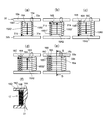
- a pressure molding machine 40 When the unmolded coil 17 is pressure-molded, a pressure molding machine 40 is used. As shown in FIGS. 5A to 5C, the pressure molding machine 40 includes a jig 41, a pair of support plates 42, 42, a pair of front and rear punches 43, 43, and a pair of upper and lower sides. Front punches 44, 44 and a pair of upper and lower rear punches 45, 45 are provided.
- the jig 41 holds the unformed coil 17 in a horizontal posture in which the radial direction coincides with the horizontal direction while fitting the hole 18 of the unformed coil 17.
- the unshaped coil 17 held by the jig 41 has an outer shape of a substantially rectangular shape or a substantially square shape (in this example, a substantially rectangular shape) (see FIG. 5C).
- the outer shape of the substantially rectangular shape of the unformed coil 17 has a substantially arc shape at the four corners. That is, the outer shape of the non-molded coil 17 includes the left and right straight portions 17a and 17a which are two long sides facing each other in the rectangle, and the front and the rear which are two short sides facing each other in the rectangle. Straight line portions 17b and 17b and four arc portions 19 (corresponding to four corner portions) are provided.
- the pair of support plates 42 and 42 support the outer surfaces of the straight portions 17a and 17a (see FIG. 5C), respectively.
- the pair of front and rear punches 43, 43 press-mold the outer surfaces of the straight portions 17b, 17b.
- the pair of upper and lower front punches 44 and 44 and rear punches 45 and 45 press-mold the upper and lower outer surfaces of the linear portions 17b and 17b, respectively.
- the upper front punch 44 has a through hole (not shown) through which the first projecting portion 15a and the second projecting portion 15b projecting outward from the unformed coil 17 in the vertical direction can be inserted. Accordingly, the upper front punch 44 can move downward without interfering with the first and second projecting portions 15a and 15b during pressure molding.
- the upper and lower front punches 44, 44 contact and pressurize the upper and lower outer surfaces of the front straight portion 17b, and the upper and lower rear punches 45, 45 touch the upper and lower outer surfaces of the rear straight portion 17b. Apply pressure. Due to these pressurizations, the unshaped coil 17 is formed such that the straight portions 17a and 17a and the straight portions 17b and 17b except the arc portion 19 are smoothly formed. As a result, the coil 10 having a substantially rectangular cross section in which the arc portion 19 has a substantially arc shape and the straight portions 17a, 17a, 17b, and 17b excluding the arc portion 19 are formed smoothly is obtained.
- the first to fourth conductor cylinder portions 16A to 16D are respectively provided.
- the first connection portions 15B1, 15B1 ′, 15B1 ′′ and the second connection portions 15B2, 15B2 ′, 15B2 ′′ are not molded. .
- the first projecting portion 15a and the second projecting portion 15b that project in the vertical direction from the coil 10 correspond to the four corner regions R1 to R4 corresponding to the four arc portions 19 of the coil 10, respectively. Among them, it is located at any one (in this example, the right front corner R1). If any one of the corner regions R1 to R4 is not specified, it will be simply referred to as “corner region R” as appropriate hereinafter.
- a current is supplied to the conductor 15 via the first protrusion 15a and the second protrusion 15b, and the conductors 15 are bonded to each other by fusion of the insulating coating due to heat generation of the conductor 15. Insulated and solidified for use.
- a thermosetting adhesive is applied from the outside of the coil 10, and the adhesive is heat-cured to bond and solidify the conductors 15 together. May be.
- the plurality of coils 10 are respectively attached to the armature base 7 of the armature 3.
- the conductor cylinder portions 16A to 16D are configured by winding the conductor 15 in a predetermined circumferential direction while winding the conductor 15 while shifting it by one pitch in the vertical direction perpendicular to the circumferential direction.
- each of a plurality of winding portions 15A provided along the axial direction includes the parallel portions 15A1 and 15A2, the first connection portion 15B1, and the second connection portion 15B2. ing.
- the outer shape of the coil 10 is substantially rectangular, and the four corners are arc portions 19.
- the first connection portion 15B1 and the second connection portion 15B2 that can be so-called stepped portions are arranged in the corner region R (see FIG. 5C) corresponding to the arc portion 19.
- connection portions 15B1 and 15B2 are provided in the corner region R, the raised portion does not exist in other regions.
- region R corresponding to the said linear part 17a, 17a, 17b, 17b can fully be pressurized, and the surface of the said linear part 17a, 17a, 17b, 17b can be smoothed.
- the linear portion 17a or 17b of the coil 10 is sufficiently adhered to the inner surface 11a of the recess 11 of the bracket 9. Can do. Therefore, the heat generated from the coil 10 can be dissipated from the close contact portion to the armature base 7 side and efficiently cooled.
- the first protrusion 15a on the winding start side and the second protrusion 15b on the winding end side for connecting and connecting the conductor 15 of the coil 10 to the outside of the coil include the corner region R. Is provided. Thereby, the smoothness of the surface of the rectangular straight portions 17a, 17a, 17b, and 17b is ensured regardless of the presence of the protruding portions 15a and 15b.
- each protrusion part 15a, 15b is provided so that it may protrude in the up-down direction instead of radial direction. As a result, the size of the entire coil 10 in the radial direction can be prevented from being increased, and the space required for mounting the coil 10 can be reduced. Therefore, it is possible to prevent the linear motor 1 from being enlarged in the traveling direction (left-right direction in FIG. 2) or in the width direction (left-right direction in FIG. 1) orthogonal thereto.
- the first projecting portion 15a and the second projecting portion 15b are arranged in one common corner region R (corner region R1 in the above example) among the corner regions R1 to R4.
- corner region R1 corner region
- the distance between the two projecting portions 15a and 15b is made closer, and the connection structure with the linear motor 1 side Can be reliably reduced in size.
- the first projecting portion 15a and the second projecting portion 15b are not limited to being disposed in one common corner region R, and may be disposed in different corner regions R.
- both ends of a specific short side that is, corner regions R1 and R4 corresponding to both ends of the front straight portion 17b or corners corresponding to both ends of the rear straight portion 17b. It is preferable to distribute and arrange the regions R2 and R3, respectively. This has the following significance.
- the corner region R1 and the corner region R2 (or the corner region) corresponding to both ends along the linear portion 17a corresponding to the long side.
- R3 and corner region R4 when the first projecting portion 15a and the second projecting portion 15b are separately arranged, the distance between the two projecting portions 15a and 15b is greatly separated, and the linear motor 1 side This leads to an increase in the connection structure. Therefore, by arranging the first projecting portion 15a and the second projecting portion 15b in the corner region R1 and the corner region R4 (or the corner region R2 and the corner region R3), the two projecting portions 15a and 15b are arranged. The distance between each other can be made relatively small, and the connection structure can be miniaturized.
- one of the two connecting portions that can be the stepped-up portion (the first connecting portion 15B1 in the above example) is provided in the left front corner region R4, and the other (the second connecting portion in the above example).
- the connection portion 15B2) is provided in the corner region R1 on the right front side
- the present invention is not limited to this. That is, for example, one of the two connecting portions is provided in the left rear corner region R3 and the other is positioned on the right front side so as to be arranged at the two corners R opposing the diagonal of the substantially rectangular shape described above. May be provided in the corner region R1.
- connection portions B1 and B2 may be provided in the corner region R2 on the right rear side, and the other may be provided in the corner region R4 on the left front side.
- connection portions B1 and B2 may be provided in the corner region R2 on the right rear side, and the other may be provided in the corner region R4 on the left front side.
- the linear motor 1 has been described by taking as an example the case where the field 2 is configured as a stator and the armature 3 is configured as a mover, but is not limited thereto. That is, the rotary electric machine may be configured with the armature 3 as a stator and the field 2 as a mover.
- the conductor 15 of the coil 10 is a round copper wire.
- a flat rectangular wire (flat copper wire) having a flat rectangular cross section may be used as the conductor 15.
- FIGS. 6A to 6F show an example of the winding process similar to FIG. 3 in such a modification.
- the state shown in FIG. 6A corresponds to FIG. 3B
- the state shown in FIG. 6B corresponds to FIG. 3D
- the state shown in FIG. 6 (d) corresponds to FIG. 3 (i)
- the state shown in FIG. 6 (e) corresponds to FIG. 3 (i)
- the state shown in FIG. 6F corresponds to FIG.
- the winding of the conductor 15 in the present modification is the same as that in the first embodiment except that a flat wire is used as the conductor 15.
- This modification also achieves the same effect as the first embodiment.
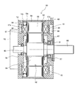
- the rotating electrical machine 50 of the present embodiment includes a rotor 52 that is a field that is rotatably supported, a substantially cylindrical stator 53 that is an armature, and a cylindrical frame 55.
- the load-side bracket 56, the load-side bearing 57, the anti-load-side bracket 58, the anti-load-side shaft 59, and the shaft 60 (corresponding to a rotating shaft).
- the rotary electric machine 50 is an embedded magnet synchronous motor including a rotor 52 inside a stator 53.
- the frame 55 is provided on the outer peripheral side of the stator 53.
- the load side bracket 56 is provided on the load side of the frame 55 (right side in FIG. 7).
- the anti-load side bracket 58 is provided on the anti-load side (left side in FIG. 7) of the frame 55.
- the load side bracket 56 and the anti-load side bracket 58 are fastened to the frame 55 by bolts (not shown).
- the load-side bearing 57 has an outer ring fitted to the load-side bracket 56.
- the anti-load side bearing 59 has an outer ring fitted to the anti-load side bracket 58.
- the shaft 60 is rotatably supported by the load side bracket 56 and the anti-load side bracket 58 via the load-side bearing 57 and the anti-load side bearing 59.
- An encoder 62 that detects the rotational position of the rotor 52 is provided on the opposite side of the shaft 60 (left side in FIG. 7).
- the load side bracket 56 is provided with a dust seal 61 on the outer side in the axial direction (right side in FIG. 7) than the load side bearing 57 in order to prevent foreign matter from entering the rotor 52.
- the rotor 52 includes a substantially cylindrical rotor core 64 having an axial hole 63 and a plurality of axial permanent magnets (not shown) embedded in the rotor core 64 for each pole. .
- the rotor 52 is configured as a field portion having a multi-pole embedded magnet structure.
- the shaft 60 is fitted in the hole 63 of the rotor core 64.
- the stator 53 is provided so as to surround the outer circumferential side of the rotor 52 in the radial direction with a magnetic gap therebetween, and is fixed to the load side bracket 56 and the anti-load side bracket 58.
- the stator 53 includes a substantially cylindrical stator core 66 (stator core) and the plurality of coils 10 attached to the stator core 66.
- the stator core 66 includes a plurality of teeth (not shown) arranged in the circumferential direction in the radial direction, and a slot (not shown) is formed between two adjacent teeth. Each coil 10 is accommodated in the slot while fitting the hole 18 on the inner peripheral side to the tooth.
- Each coil 10 is housed in a recess 67 of the load side bracket 56 and the anti-load side bracket 58 on the load side and the anti-load side of the coil 10 exposed from the stator core 66. Specifically, each coil 10 is in a state where the linear portions 17b and 17b (or 17a and 17a) of each coil 10 are in close contact with the inner surface 67a of the recess 67 of the load side bracket 56 and the anti-load side bracket 58. Is arranged.
- each coil 10 The detailed configuration of each coil 10 and the method of winding the conductor 15 and pressure forming are the same as those in the first embodiment described above with reference to FIGS. That is, in each coil 10, the conductor cylinders 16A to 16D are configured by winding the conductor 15 in a predetermined circumferential direction while winding the conductor 15 while shifting by one pitch in the first direction orthogonal to the circumferential direction. ing.
- a refrigerant flow path 68 is installed in the load side bracket 56 and the anti-load side bracket 58 so as to be close to the coil 10 accommodated in the recess 67.
- the refrigerant flow path 68 circulates a predetermined refrigerant (for example, cooling water) supplied from the external pipe 69 to cool the heat generated by the coil 10.
- a connecting portion 14 is provided between the coil 10 and the frame 55 on the opposite side of the stator core 66.
- an external power source is connected to the first projecting portion 15a and the second projecting portion 15b projecting from the coil 10 via a connection unit (not shown), and the connection unit and projecting units 15a and 15b and the connection are connected from the external power source. Power is supplied to the coil 10 through the portion 14b.
- each of a plurality of winding portions 15A provided along the axial direction includes the parallel portions 15A1 and 15A2, the first connection portion 15B1, and the second connection portion 15B2. ing.
- the first connection portion 15B1 and the second connection portion 15B2 that can be so-called stepped portions are arranged in the corner region R (see FIG. 5C) corresponding to the arc portion 19. Since the connecting portions 15B1 and 15B2 are provided in the corner region R, the raised portion does not exist in other regions. Thereby, the area
- the linear portions 17b and 17b (or 17a and 17a) of the coil 10 are placed on the inner surface 67a of the recess 67. It can be sufficiently adhered. As a result, the heat generated from the coil 10 can be dissipated from the close contact portion to the brackets 56, 58, the stator core 66, and the like, thereby efficiently cooling.
- each of the plurality of coils 10 is disposed so as to be in close contact with the recesses 67 of the load-side bracket 56 and the anti-load-side bracket 58 that face each other in the axial direction of the shaft 60. .
- the coil 10 is sufficiently brought into close contact with both the load side bracket 56 and the anti-load side bracket 58, so that the heat generated from the coil 10 is transmitted from the close contact portion to both the load side and the anti load side brackets 56. , 58 to dissipate heat and ensure efficient cooling.
- a refrigerant flow path 68 for circulating the refrigerant is provided at a portion of the load side bracket 56 and the anti-load side bracket 58 that faces the coil 10 in the axial direction of the shaft 66.
- the projecting portions 15a and 15b of the coil 10 are provided so as to project in the first direction (axial direction of the coil), not in the second direction (so-called radial direction).
- the size of the entire coil 10 in the second direction can be prevented from increasing, so that the second direction of the coil 10 is arranged along the axial direction of the shaft 60 as shown in FIG. In this case, it is possible to prevent the rotating electric machine 50 from being enlarged in the axial direction along the shaft 60.
- the rotating electric machine 50 has been described by taking as an example the case where the field is the rotor 52 and the armature is the stator 53, but the rotating electric machine 50 is the rotor and the field is the stator. It may be configured.
Landscapes
- Engineering & Computer Science (AREA)
- Power Engineering (AREA)
- Physics & Mathematics (AREA)
- Chemical & Material Sciences (AREA)
- Combustion & Propulsion (AREA)
- Electromagnetism (AREA)
- Manufacturing & Machinery (AREA)
- Windings For Motors And Generators (AREA)
- Manufacture Of Motors, Generators (AREA)
Description
まず、図1及び図2を用いて、第1実施形態のリニアモータについて説明する。
図1及び図2に示すように、本実施形態のリニアモータ1は、固定子を構成する界磁2と、可動子を構成する電機子3と、を備えている。界磁2は、ヨーク取付部4に設置された界磁ヨーク5と、界磁ヨーク5上に配置された複数個の永久磁石6と、を備えている。複数個の永久磁石6は、界磁ヨーク5の長手方向(電機子3の移動方向)に沿って等ピッチで隣接しつつ、かつ交互に極性が異なるように、配置されている。
上記構成のリニアモータ1において、本実施形態の特徴は、コイル10の表面を平滑とするための導体15(後述の図3等参照)の巻回手法にある。以下、その詳細を順を追って説明する。コイル10は、概略的に、導体15を周回方向に巻回する第1工程と、第1工程により得られた未成形コイル17(後述の図4等参照)の所定部位を加圧成形する第2工程と、により製造される。
次に、図3(a)~(k)及び図4(a)~(d)を用いて、上記第1工程を説明する。なお、以下の説明において、上下方向(高さ方向)、前後方向、左右方向は、図3(a)~(j)、図3(k)、図4(a)~(d)等の各図中に適宜示す矢印方向に対応している。第1工程では、導体15を略水平方向に沿う周回方向に巻回することを繰り返し、径方向に積層した複数の導体筒部16(後述)が形成される。導体15は、絶縁性能及び熱融着性能を有する樹脂で被覆したボンド線の丸銅線である。
<巻回用治具>
導体15を巻回する際には、所定の姿勢で配置された巻回用治具30が用いられる。この巻回用治具30は、この例では略長方形状の水平断面を有する略直方体状のコアピン部31を備えている。このコアピン部31は、図示しない適宜の嵌合構造によって高さ方向略半分の位置(図3(a)(j)中の点線h参照)で上下に2分割可能になっている。この分割されたコアピン部31の上側半分の上端部に上スペーサ部32aが一体的に設けられ、コアピン部31の下側半分の下端部に下スペーサ部32bが一体的に設けられている。なお、上スペーサ部32aには、図3(k)に示すように、導体15を通す貫通孔33a,33bが設けられている。貫通孔33a,33bは、コアピン部31の4つの隅部31a,31b,31c,31dのうちの1つの隅部(この例では右前側の第1隅部31a)に近接した位置と、その径方向外側位置とに、それぞれ設けられている。
まず、図3(a)に示すように、導体15を上スペーサ部32aの貫通孔33aから上方に所定量延出し、第1突出部15aとする。その後、上スペーサ部32aの下面の近傍で、導体15のうち上記第1突出部15aに続く部分を、コアピン部31の右前側の第1隅部31aを周回の始点15sとして、当該第1隅部31a→右後側の第2隅部31b→左後側の第3隅部31c→左前側の第4隅部31d→右前側の第1隅部31aのようにコアピン部31の周囲に一周巻回する。
その後、上記同様にして、上記2番目の巻回部15Aを形成する。すなわち、上記第1隅部31aにおいて1番目の巻回部15Aの始点15sから1ピッチ下方にずれて位置している始点15sから、第2隅部31b→第3隅部31c→第4隅部31dと水平方向に導体15を延設して上記延設部15A1-1,15A1-2,15A1-3からなる第1平行部15A1を形成する。その後、前述と同様、上記第4隅部31dにおいて斜めとなる方向に延びる第1接続部15B1を介し、上記第1隅部31aに位置する終点15eに向けて水平方向に延びる第2平行部15A2が形成される。その後、上記第1隅部31aにおいて、斜めとなる方向に伸びる第2接続部15B2により、上記第2平行部15A2と次の3番目の巻回部15Aとが接続される。以上により、第1平行部15A1、第1接続部15B1、第2平行部15A2、及び第2接続部15B2からなる2番目の巻回部15Aが完成する。このとき、上記2番目の巻回部15Aの第1平行部15A1、第1接続部15B1、第2平行部15A2、及び第2接続部15B2は、上記1番目の巻回部15Aの第1平行部15A1、第1接続部15B1、第2平行部15A2、及び第2接続部15B2から、それぞれ1ピッチ下方にずれて位置している。
最下段の巻回部15Aでは、延設部15A1-1,15A1-2,15A1-3からなる第1平行部15A1は上述した他の段の巻回部15Aと同様であるが、第1接続部15B1′、第2平行部15A2、及び第2接続部15B2′、は他の段の巻回部15Aと巻回態様が異なる。
上記第1導体筒部16Aが形成された後は、その径方向外周側に、次の第2の導体筒部16Bが、上記と同様の導体の巻回手法(但し巻回部15Aを上方へ順次ずらしながら形成する)により形成される。すなわち、上記第1導体筒部16Aの最下段の巻回部15Aに備えられた第2接続部15B2′が、上記第2の導体筒部16Bの最下段(下から1番目)の巻回部15Aの始点15sに接続される。この1番目の巻回部15Aにおいては、第1隅部31a近傍に位置する上記始点15sから、上記同様、第2隅部31b近傍に向けて導体15が延設され(延設部15A1-1)、さらに第3隅部31c近傍に向けて導体15が延設され(延設部15A1-2)、さらに第4隅部31d近傍に向けて導体15が延設され(延設部15A1-3)、これによって、上記始点15sに対し同一ピッチにある第1平行部15A1が形成される。
その後、上記同様にして、第2導体筒部16Bの上記2番目の巻回部15Aを形成する。すなわち、上記第1隅部31a近傍において1番目の巻回部15Aの始点15sから1ピッチ上方にずれて位置している始点15sから、第2隅部31b近傍→第3隅部31c近傍→第4隅部31d近傍と水平方向に導体15を延設して上記延設部15A1-1,15A1-2,15A1-3からなる第1平行部15A1を形成する。その後、前述と同様、上記第4隅部31d近傍において斜めとなる方向に延びる第1接続部15B1″を介し、上記第1隅部31a近傍に位置する終点15eに向けて水平方向に延びる第2平行部15A2が形成される。その後、上記第1隅部31a近傍において、斜めとなる方向に伸びる第2接続部15B2′により、上記第2平行部15A2と次の3番目(下から3番目)の巻回部15Aとが接続される。以上により、第1平行部15A1、第1接続部15B1″、第2平行部15A2、及び第2接続部15B2′からなる2番目の巻回部15Aが完成する。このとき、上記2番目の巻回部15Aの第1平行部15A1、第1接続部15B1″、第2平行部15A2、及び第2接続部15B2′は、上記1番目の巻回部15Aの第1平行部15A1、第1接続部15B1″、第2平行部15A2、及び第2接続部15B2′から、それぞれ1ピッチ上方にずれて位置している。
最上段の巻回部15Aでは、第1平行部15A1、第1接続部15B1″、及び第2平行部15A2は上述した他の段の巻回部15Aと同様であるが、第2接続部15B2″の巻回態様が他の段の巻回部15Aと異なる。
上記第2導体筒部16Bが形成された後は、その径方向外周側に、次の第3の導体筒部16Cが、上記と同様の導体の巻回手法(巻回部15Aを下方へ順次ずらしながら形成する)により形成される。すなわち、上記第2導体筒部16Bの最上段の巻回部15Aに備えられた第2接続部15B2″が、上記第3の導体筒部16Cの最上段(上から1番目)の巻回部15Aの始点15sに接続される。この1番目の巻回部15Aにおいては、第1隅部31a近傍に位置する上記始点15sから、上記同様、第2隅部31b近傍に向けて導体15が延設され(延設部15A1-1)、さらに第3隅部31c近傍に向けて導体15が延設され(延設部15A1-2)、さらに第4隅部31d近傍に向けて導体15が延設され(延設部15A1-3)、これによって、上記始点15sに対し同一ピッチにある第1平行部15A1が形成される。
その後、上記同様にして、第3導体筒部16Cの上記2番目の巻回部15Aを形成する。すなわち、上記第1隅部31a近傍において1番目の巻回部15Aの始点15sから1ピッチ下方にずれて位置している始点15sから、第2隅部31b近傍→第3隅部31c近傍→第4隅部31d近傍と水平方向に導体15を延設して上記延設部15A1-1,15A1-2,15A1-3からなる第1平行部15A1を形成する。その後、前述と同様、上記第4隅部31d近傍において斜めとなる方向に延びる第1接続部15B1を介し、上記第1隅部31a近傍に位置する終点15eに向けて水平方向に延びる第2平行部15A2が形成される。その後、上記第1隅部31a近傍において、斜めとなる方向に伸びる第2接続部15B2により、上記第2平行部15A2と次の3番目(上から3番目)の巻回部15Aとが接続される。以上により、第1平行部15A1、第1接続部15B1、第2平行部15A2、及び第2接続部15B2からなる2番目の巻回部15Aが完成する。このとき、上記2番目の巻回部15Aの第1平行部15A1、第1接続部15B1、第2平行部15A2、及び第2接続部15B2は、上記1番目の巻回部15Aの第1平行部15A1、第1接続部15B1、第2平行部15A2、及び第2接続部15B2から、それぞれ1ピッチ下方にずれて位置している。
最下段の巻回部15Aでは、第1平行部15A1は上述した他の段の巻回部15Aと同様であるが、第1接続部15B1′、第2平行部15A2、第2接続部15B2′の巻回態様が他の段の巻回部15Aと異なる。
上記第3導体筒部16Cが形成された後は、その径方向外周側に、次の第4の導体筒部16Dが、上記と同様の導体の巻回手法(巻回部15Aを上方へ順次ずらしながら形成する)により形成される。すなわち、上記第3導体筒部16Cの最下段の巻回部15Aに備えられた第2接続部15B2′が、上記第4の導体筒部16Dの最下段(下から1番目)の巻回部15Aの始点15sに接続される。この1番目の巻回部15Aにおいては、第1隅部31a近傍に位置する上記始点15sから、上記同様、第2隅部31b近傍に向けて導体15が延設され(延設部15A1-1)、さらに第3隅部31c近傍に向けて導体15が延設され(延設部15A1-2)、さらに第4隅部31d近傍に向けて導体15が延設され(延設部15A1-3)、これによって、上記始点15sに対し同一ピッチにある第1平行部15A1が形成される。
その後、上記同様にして、第4導体筒部16Dの上記2番目の巻回部15Aを形成する。すなわち、上記第1隅部31a近傍において1番目の巻回部15Aの始点15sから1ピッチ上方にずれて位置している始点15sから、第2隅部31b近傍→第3隅部31c近傍→第4隅部31d近傍と水平方向に導体15を延設して上記延設部15A1-1,15A1-2,15A1-3からなる第1平行部15A1を形成する。その後、前述と同様、上記第4隅部31d近傍において斜めとなる方向に延びる第1接続部15B1″を介し、上記第1隅部31a近傍に位置する終点15eに向けて水平方向に延びる第2平行部15A2が形成される。その後、上記第1隅部31a近傍において、斜めとなる方向に伸びる第2接続部15B2′により、上記第2平行部15A2と次の3番目(下から3番目)の巻回部15Aとが接続される。以上により、第1平行部15A1、第1接続部15B1″、第2平行部15A2、及び第2接続部15B2′からなる2番目の巻回部15Aが完成する。このとき、上記2番目の巻回部15Aの第1平行部15A1、第1接続部15B1″、第2平行部15A2、及び第2接続部15B2′は、上記1番目の巻回部15Aの第1平行部15A1、第1接続部15B1″、第2平行部15A2、及び第2接続部15B2′から、それぞれ1ピッチ上方にずれて位置している。
最上段の巻回部15Aでは、上述した他の段の巻回部15Aと同様の第1平行部15A1、第1接続部15B1″、及び第2平行部15A2を備える。なお、第2接続部15B2″は省略される。以上の結果、最下段から最上段まで上下方向に沿って配列された、複数の巻回部15Aからなる第4導体筒部16D(最外周側に位置する導体筒部に相当)が形成される(図3(i)参照)。そして、上記第4導体筒部16Dの最上段の第2平行部15A2の末端にさらに連続する導体15を、コアピン31の第1隅部31a近傍において上スペーサ32aの上記貫通孔33bから上方に延出する。貫通孔33bから延出した導体15は、所定位置で切断して、残存した導体15が他方の結線部15bとされる。
図5(a)~(c)を用いて、上記第2工程を説明する。なお、以下の説明において、上下方向(高さ方向)、前後方向、左右方向は、図5(a)~(c)等の各図中に適宜示す矢印方向に対応している。
未成形コイル17を加圧成形する際には、加圧成形機40が用いられる。加圧成形機40は、図5(a)~(c)に示すように、治具41と、1対の支持プレート42,42と、前後1対のパンチ43,43と、上下1対の前パンチ44,44と、上下一対の後パンチ45,45と、を備えている。
上記加圧成形機40を用いた未成形コイルの加圧成形時には、まず、図5(a)に示すように、前後のパンチ43,43、上下の前パンチ44,44、上下の後パンチ45,45が、矢印方向に未成形コイル17へ近接する。その後、図5(b)及び図5(c)に示すように、前後のパンチ43,43が上記直線部17b,17bの外面に接触して加圧を行う。また、上下の前パンチ44,44が前側の直線部17bの上下の外面に接触し加圧を行い、上下の後パンチ45,45が後側の直線部17bの上下の外面に接触して加圧を行う。これらの加圧により、未成形コイル17は、上記円弧部19を除く上記直線部17a,17a及び直線部17b,17bが平滑に成形される。これにより、円弧部19が略円弧状で、円弧部19を除く直線部17a,17a、17b,17bが平滑に成形された断面略長方形のコイル10が得られる。
以上説明したように、本実施形態のリニアモータ1においては、電機子3の電機子ベース7に複数のコイル10がそれぞれ取り付けられる。各コイル10では、導体15を所定の周回方向に周回させつつ、周回方向に直交する上下方向に1ピッチずつずらしながら巻回することで、導体筒部16A~16Dが構成されている。
次に、図7を用いて、第2実施形態の回転電機について説明する。
図7に示すように、本実施形態の回転電機50は、回転自在に支持された界磁である回転子52と、電機子である略円筒状の固定子53と、円筒状のフレーム55と、負荷側ブラケット56と、負荷側軸受57と、反負荷側ブラケット58と、反負荷側軸59と、シャフト60(回転軸に相当)と、を有する。回転電機50は、この例では、固定子53の内側に回転子52を備えた、埋込磁石同期モータである。
固定子53は、回転子52の径方向外周側を、磁気的空隙を空けて囲むように設けられ、上記負荷側ブラケット56及び上記反負荷側ブラケット58に固定されている。固定子53は、略円筒状の固定子コア66(固定子鉄心)と、固定子コア66に装着された複数の上記コイル10と、を有している。固定子コア66は、周方向に配列した径方向の図示しない複数のティースを備え、隣り合う2つのティース間に図示しないスロットが形成されている。各コイル10は、内周側の穴部18を上記ティースに嵌合しつつ、上記スロットに収容されている。また各コイル10は、固定子コア66から露出したコイル10の負荷側及び反負荷側が、それぞれ負荷側ブラケット56及び反負荷側ブラケット58の凹部67に収納されている。詳細には、各コイル10の上記直線部17b,17b(又は17a,17a)が、上記負荷側ブラケット56及び上記反負荷側ブラケット58の上記凹部67の内面67aに密着した状態で、各コイル10は配置されている。
以上のように構成した本実施形態の回転電機50においても、上記第1実施形態と同様の効果を得る。すなわち、固定子コア66の上記複数のスロットに複数のコイル10がそれぞれ挿入配置されている。各コイル10では、導体15を所定の周回方向に周回させつつ、周回方向に直交する前述の第1方向に1ピッチずつずらしながら巻回することで、導体筒部16A~16Dが構成されている。各導体筒部16においては、軸方向に沿って複数備えられる巻回部15Aのそれぞれが、上記平行部15A1,15A2と、上記第1接続部15B1と、上記第2接続部15B2と、を備えている。コイル10の外形状を略長方形としつつ、その四隅が円弧部19となっている。そして、いわゆる段上がり部となりうる上記第1接続部15B1及び第2接続部15B2が、上記円弧部19に対応した隅部領域R(図5(c)参照)に配置されている。接続部15B1,15B2が隅部領域Rに設けられることで、それ以外の領域には上記段上がり部が存在しなくなる。これにより、上記直線部17a,17a,17b,17bに対応した上記隅部領域R以外の領域を十分に加圧して、上記直線部17a,17a,17b,17bの表面を平滑にすることができる。これにより、上記のようにコイル10を回転電機50のスロットの凹部67に装着して使用するとき、コイル10の上記直線部17b,17b(又は17a,17a)を、上記凹部67の内面67aに十分に密着させることができる。この結果、コイル10から発生する熱を当該密着部分からブラケット56,58や固定子コア66等へと放熱し効率よく冷却することができる。
2 界磁
3 電機子
6 永久磁石
7 電機子ベース
8 コア
9 ブラケット
10 コイル
11 凹部
14 結線部
15 導体
15a 第1突出部
15b 第2突出部
15A 巻回部
15A1 第1平行部(平行部)
15A2 第2平行部(平行部)
15B1 第1接続部(接続部)
15B1′ 第1接続部(接続部)
15B1″ 第1接続部(接続部)
15B2 第2接続部(接続部)
15B2′ 第2接続部(接続部)
15B2″ 第2接続部(接続部)
15e 終点
15s 始点
16A~16D 導体筒部
17 未成形コイル
19 円弧部(四隅部)
50 回転電機
52 回転子
53 固定子
56,58 ブラケット
60 シャフト(回転軸)
66 固定子コア(固定子鉄心)
67 凹部
68 冷媒流路
R1~4 隅部領域(四隅部に対応する部位)
Claims (14)
- 導体を所定の周回方向に略沿って始点から終点まで一周巻回し1つの巻回部を生成した後に、前記導体を前記周回方向に直交する第1方向に1ピッチずらしてさらに前記周回方向に略沿って一周させ、前記1つの巻回部の前記第1方向に隣接する別の巻回部を順次生成することにより、前記第1方向に沿って配列された複数の巻回部からなる導体筒部を形成し、
1つの前記導体筒部を形成した後に、当該1つの導体筒部の、前記第1方向に直交する第2方向に隣接する別の導体筒部を順次形成することにより、前記第2方向に沿って複数の導体筒部を配列した、コイルであって、
前記導体は、
前記第1方向から見た前記コイルの外形状が、四隅部を略円弧形状とした略長方形又は略正方形となるように、巻回されており、
前記1つの巻回部は、
前記第1方向における位置が、前記始点と同一ピッチとなるか若しくは前記1ピッチの半分である半ピッチだけ前記始点とずれるように、前記周回方向に延設される、少なくとも1つの平行部と、
前記第1方向における位置が互いに前記半ピッチだけずれた2つの前記平行部どうしを接続するか、若しくは、前記第1方向における位置が互いに前記半ピッチだけずれる1つの前記平行部の末端に位置する前記終点と前記別の巻回部の前記始点とを接続する、少なくとも1つの接続部と、
を備えるとともに、
前記接続部が、前記四隅部のいずれかに対応する部位に配置されている
ことを特徴とするコイル。 - 請求項1記載のコイルにおいて、
各導体筒部の前記導体は、
前記コイルの前記外形状における前記略長方形又は前記略正方形のうち前記四隅部を除く2組の対向する2辺となる部位が、加圧成形されている
ことを特徴とするコイル。 - 請求項1又は請求項2記載のコイルにおいて、
前記第2方向に沿って最内周側に位置する前記導体筒部の、前記第1方向に沿った端部に位置する巻き始めの前記巻回部の前記始点から、前記第1方向に沿って当該巻回部の外方へと突出する第1突出部と、
前記第2方向に沿って最外周側に位置する前記導体筒部の、前記第1方向に沿った端部に位置する巻き終わりの前記巻回部の前記終点から、前記第1方向に沿って当該巻回部の外方へと突出する第2突出部と、
を有し、
前記第1突出部及び前記第2突出部は、
前記四隅部のいずれかに対応する部位に配置されている
ことを特徴とするコイル。 - 請求項3記載のコイルにおいて、
前記コイルの前記外形状は、
互いに対向する2つの長辺と互いに対向する2つの短辺とを備える前記略長方形であり、
前記第1突出部及び前記第2突出部は、
前記四隅部のうち、特定の1つの短辺の両端に位置する2つの隅部に対応する部位に、それぞれ振り分け配置されている
ことを特徴とするコイル。 - 請求項3記載のコイルにおいて、
前記第1突出部及び前記第2突出部は、
前記四隅部のうち、共通の1つの隅部に対応する部位に配置されている
ことを特徴とするコイル。 - 回転軸を備えた回転子と、前記回転軸を負荷側及び反負荷側でそれぞれ回転可能に支持する負荷側ブラケット及び反負荷側ブラケットと、前記回転子の外周側を囲むように設けられ、前記負荷側ブラケット及び前記反負荷側ブラケットにそれぞれ固定された略円筒状の固定子と、を有し、
前記固定子は、前記略円筒状の周方向に複数のスロットを配列した固定子コアと、前記複数のスロットに挿入される複数のコイルと、を備える回転電機であって、
前記複数のコイルのそれぞれは、
導体を所定の周回方向に略沿って始点から終点まで一周巻回し1つの巻回部を生成した後に、前記導体を前記周回方向に直交する第1方向に1ピッチずらしてさらに前記周回方向に略沿って一周させ、前記1つの巻回部の前記第1方向に隣接する別の巻回部を順次生成することにより、前記第1方向に沿って配列された複数の巻回部からなる導体筒部を形成し、1つの前記導体筒部を形成した後に、当該1つの導体筒部の、前記第1方向に直交する第2方向に隣接する別の導体筒部を順次形成することにより、前記第2方向に沿って複数の導体筒部を配列しており、かつ、
前記導体は、
前記第1方向から見た前記コイルの外形状が、四隅部を略円弧形状とした略長方形又は略正方形となるように、巻回されており、
前記1つの巻回部は、
前記第1方向における位置が、前記始点と同一ピッチとなるか若しくは前記1ピッチの半分である半ピッチだけ前記始点とずれるように、前記周回方向に延設される、少なくとも1つの平行部と、
前記第1方向における位置が互いに前記半ピッチだけずれた2つの前記平行部どうしを接続するか、若しくは、前記第1方向における位置が互いに前記半ピッチだけずれる1つの前記平行部の末端に位置する前記終点と前記別の巻回部の前記始点とを接続する、少なくとも1つの接続部と、
を備えるとともに、
前記接続部が、前記四隅部のいずれかに対応する部位に配置されている
ことを特徴とする回転電機。 - 請求項6記載の回転電機において、
前記複数のコイルそれぞれの各導体筒部の前記導体は、
外形状が対応する前記スロットの形状に合致するように、前記略長方形又は前記略正方形のうち前記四隅部を除く2組の対向する2辺となる部位が加圧成形されている
ことを特徴とする回転電機。 - 請求項6又は請求項7記載の回転電機において、
前記複数のコイルのそれぞれは、
前記回転軸の軸方向にそれぞれ対向する前記負荷側ブラケット及び前記反負荷側ブラケットに対し略密着するようにして配置されていることを特徴とする回転電機。 - 請求項8記載の回転電機において、
前記負荷側ブラケット及び前記反負荷側ブラケットは、
前記コイルに対し軸方向に対向する部位に、冷媒を流通させる流路を備えている
ことを特徴とする回転電機。 - 請求項6乃至請求項9のいずれか1項記載の回転電機において、
前記複数のコイルのそれぞれは、
前記第2方向に沿って最内周側に位置する前記導体筒部の、前記第1方向に沿った端部に位置する巻き始めの前記巻回部の前記始点から、前記第1方向に沿って当該巻回部の外方へと突出する第1突出部と、
前記第2方向に沿って最外周側に位置する前記導体筒部の、前記第1方向に沿った端部に位置する巻き終わりの前記巻回部の前記終点から、前記第1方向に沿って当該巻回部の外方へと突出する第2突出部と、
を有し、
前記第1突出部及び前記第2突出部は、前記四隅部のいずれかに対応する部位に配置されており、
かつ、
前記回転電機は、さらに、
前記複数のコイルの前記第1突出部及び前記第2突出部を結線する結線部を、前記複数のコイルよりも前記略円筒状の外周側の領域に有している
ことを特徴とする回転電機。 - 複数の永久磁石を直線状に配列した界磁と、
前記複数の永久磁石と磁気的空隙を介して平行に対向配置され、電機子ベース、及び、前記電機子ベースに取り付けられた複数のコイル、を備えた電機子と、
を有し、
前記界磁と前記電機子のいずれか一方を固定子に、他方を可動子として、前記可動子を所定の進行方向に沿って走行させるリニアモータであって、
前記複数のコイルのそれぞれは、
導体を所定の周回方向に略沿って始点から終点まで一周巻回し1つの巻回部を生成した後に、前記導体を前記周回方向に直交する第1方向に1ピッチずらしてさらに前記周回方向に略沿って一周させ、前記1つの巻回部の前記第1方向に隣接する別の巻回部を順次生成することにより、前記第1方向に沿って配列された複数の巻回部からなる導体筒部を形成し、1つの前記導体筒部を形成した後に、当該1つの導体筒部の、前記第1方向に直交する第2方向に隣接する別の導体筒部を順次形成することにより、前記第2方向に沿って複数の導体筒部を配列しており、かつ、
前記導体は、
前記第1方向から見た前記コイルの外形状が、四隅部を略円弧形状とした略長方形又は略正方形となるように、巻回されており、
前記1つの巻回部は、
前記第1方向における位置が、前記始点と同一ピッチとなるか若しくは前記1ピッチの半分である半ピッチだけ前記始点とずれるように、前記周回方向に延設される、少なくとも1つの平行部と、
前記第1方向における位置が互いに前記半ピッチだけずれた2つの前記平行部どうしを接続するか、若しくは、前記第1方向における位置が互いに前記半ピッチだけずれる1つの前記平行部の末端に位置する前記終点と前記別の巻回部の前記始点とを接続する、少なくとも1つの接続部と、
を備えるとともに、
前記接続部が、前記四隅部のいずれかに対応する部位に配置されている
ことを特徴とするリニアモータ。 - 請求項11記載のリニアモータにおいて、
前記複数のコイルそれぞれの各導体筒部の前記導体は、
前記略長方形又は前記略正方形のうち前記四隅部を除く2組の対向する2辺となる部位が加圧成形されている
ことを特徴とするリニアモータ。 - 請求項11又は請求項12記載のリニアモータにおいて、
前記電機子は、
前記電機子ベースに取り付けられ、前記複数のコイルを収納配置するためのブラケットをさらに備え、
前記複数のコイルのそれぞれは、
前記ブラケットに対し略密着するようにして配置されている
ことを特徴とするリニアモータ。 - 請求項11乃至請求項13のいずれか1項記載のリニアモータにおいて、
前記複数のコイルのそれぞれは、
前記第2方向に沿って最内周側に位置する前記導体筒部の、前記第1方向に沿った端部に位置する巻き始めの前記巻回部の前記始点から、前記第1方向に沿って当該巻回部の外方へと突出する第1突出部と、
前記第2方向に沿って最外周側に位置する前記導体筒部の、前記第1方向に沿った端部に位置する巻き終わりの前記巻回部の前記終点から、前記第1方向に沿って当該巻回部の外方へと突出する第2突出部と、
を有し、
前記第1突出部及び前記第2突出部は、前記四隅部のいずれかに対応する部位に配置されており、
かつ、
前記リニアモータは、さらに、
前記複数のコイルの前記第1突出部及び前記第2突出部を結線する結線部を、前記複数のコイルと前記電機子ベースとの間の領域に有している
ことを特徴とするリニアモータ。
Priority Applications (4)
| Application Number | Priority Date | Filing Date | Title |
|---|---|---|---|
| JP2014538044A JP5928602B2 (ja) | 2012-09-28 | 2012-09-28 | コイル、回転電機、及びリニアモータ |
| PCT/JP2012/075156 WO2014049847A1 (ja) | 2012-09-28 | 2012-09-28 | コイル、回転電機、及びリニアモータ |
| CN201290001292.5U CN204633497U (zh) | 2012-09-28 | 2012-09-28 | 线圈、旋转电机及直线电机 |
| US14/645,424 US9978492B2 (en) | 2012-09-28 | 2015-03-12 | Coil, rotating electrical machine, and linear motor |
Applications Claiming Priority (1)
| Application Number | Priority Date | Filing Date | Title |
|---|---|---|---|
| PCT/JP2012/075156 WO2014049847A1 (ja) | 2012-09-28 | 2012-09-28 | コイル、回転電機、及びリニアモータ |
Related Child Applications (1)
| Application Number | Title | Priority Date | Filing Date |
|---|---|---|---|
| US14/645,424 Continuation US9978492B2 (en) | 2012-09-28 | 2015-03-12 | Coil, rotating electrical machine, and linear motor |
Publications (1)
| Publication Number | Publication Date |
|---|---|
| WO2014049847A1 true WO2014049847A1 (ja) | 2014-04-03 |
Family
ID=50387308
Family Applications (1)
| Application Number | Title | Priority Date | Filing Date |
|---|---|---|---|
| PCT/JP2012/075156 Ceased WO2014049847A1 (ja) | 2012-09-28 | 2012-09-28 | コイル、回転電機、及びリニアモータ |
Country Status (4)
| Country | Link |
|---|---|
| US (1) | US9978492B2 (ja) |
| JP (1) | JP5928602B2 (ja) |
| CN (1) | CN204633497U (ja) |
| WO (1) | WO2014049847A1 (ja) |
Cited By (1)
| Publication number | Priority date | Publication date | Assignee | Title |
|---|---|---|---|---|
| US20160365758A1 (en) * | 2014-03-19 | 2016-12-15 | Kabushiki Kaisha Yaskawa Denki | Rotating electric machine and method for producing rotating electric machine |
Families Citing this family (9)
| Publication number | Priority date | Publication date | Assignee | Title |
|---|---|---|---|---|
| WO2014030214A1 (ja) * | 2012-08-21 | 2014-02-27 | 株式会社安川電機 | コイル、回転電機、及びコイルの製造方法 |
| WO2017072912A1 (ja) * | 2015-10-29 | 2017-05-04 | 三菱電機株式会社 | 回転電機 |
| FR3056849B1 (fr) * | 2016-09-28 | 2020-11-13 | Inst Vedecom | Dissipateur thermique pour machine electrique tournante |
| US10679789B2 (en) * | 2017-05-22 | 2020-06-09 | Selco Co., Ltd. | Method of manufacturing high-density coil |
| CN107444969A (zh) * | 2017-08-25 | 2017-12-08 | 福州可源电子有限公司 | 一种绕线机 |
| WO2019161256A2 (en) * | 2018-02-15 | 2019-08-22 | The Charles Stark Draper Laboratory, Inc. | Electrostatic motor |
| CN108900030B (zh) * | 2018-09-14 | 2024-07-16 | 苏州直为精驱控制技术有限公司 | 自冷式直线电机 |
| US11881343B2 (en) | 2020-03-13 | 2024-01-23 | Cirrus Logic, Inc. | Layered process-constructed double-winding embedded solenoid inductor |
| CN117895676B (zh) * | 2023-12-29 | 2024-12-10 | 比亚迪股份有限公司 | 定子铁芯组件、定子组件、直线电机、悬架装置及车辆 |
Citations (5)
| Publication number | Priority date | Publication date | Assignee | Title |
|---|---|---|---|---|
| JPS56157232A (en) * | 1980-05-01 | 1981-12-04 | Seiko Epson Corp | Coil for driving motor of electronic clock |
| JP2000197294A (ja) * | 1998-12-24 | 2000-07-14 | Toyota Motor Corp | 集中巻コイルおよび巻線製造装置 |
| WO2004038893A1 (ja) * | 2002-10-22 | 2004-05-06 | Mitsubishi Denki Kabushiki Kaisha | 回転電機の回転子 |
| JP2005318669A (ja) * | 2004-04-27 | 2005-11-10 | Honda Motor Co Ltd | ステータ |
| JP2007089400A (ja) * | 2007-01-04 | 2007-04-05 | Sawafuji Electric Co Ltd | 回転電機のステータ |
Family Cites Families (4)
| Publication number | Priority date | Publication date | Assignee | Title |
|---|---|---|---|---|
| JP3903922B2 (ja) * | 2003-01-27 | 2007-04-11 | 株式会社デンソー | 回転電機の集中巻きステータコイル |
| JP3872055B2 (ja) * | 2003-06-20 | 2007-01-24 | 三菱電機株式会社 | リニアモータの電機子 |
| JP4059888B2 (ja) | 2005-03-31 | 2008-03-12 | 三映電子工業株式会社 | 矩形状コイルの製造方法及び矩形状コイルの製造装置 |
| JP5315743B2 (ja) * | 2008-03-26 | 2013-10-16 | アイシン精機株式会社 | 電動回転モーター |
-
2012
- 2012-09-28 JP JP2014538044A patent/JP5928602B2/ja active Active
- 2012-09-28 CN CN201290001292.5U patent/CN204633497U/zh not_active Expired - Lifetime
- 2012-09-28 WO PCT/JP2012/075156 patent/WO2014049847A1/ja not_active Ceased
-
2015
- 2015-03-12 US US14/645,424 patent/US9978492B2/en active Active
Patent Citations (5)
| Publication number | Priority date | Publication date | Assignee | Title |
|---|---|---|---|---|
| JPS56157232A (en) * | 1980-05-01 | 1981-12-04 | Seiko Epson Corp | Coil for driving motor of electronic clock |
| JP2000197294A (ja) * | 1998-12-24 | 2000-07-14 | Toyota Motor Corp | 集中巻コイルおよび巻線製造装置 |
| WO2004038893A1 (ja) * | 2002-10-22 | 2004-05-06 | Mitsubishi Denki Kabushiki Kaisha | 回転電機の回転子 |
| JP2005318669A (ja) * | 2004-04-27 | 2005-11-10 | Honda Motor Co Ltd | ステータ |
| JP2007089400A (ja) * | 2007-01-04 | 2007-04-05 | Sawafuji Electric Co Ltd | 回転電機のステータ |
Cited By (2)
| Publication number | Priority date | Publication date | Assignee | Title |
|---|---|---|---|---|
| US20160365758A1 (en) * | 2014-03-19 | 2016-12-15 | Kabushiki Kaisha Yaskawa Denki | Rotating electric machine and method for producing rotating electric machine |
| US10547219B2 (en) * | 2014-03-19 | 2020-01-28 | Kabushiki Kaisha Yaskawa Denki | Rotating electric machine having air core coil with curved end surfaces |
Also Published As
| Publication number | Publication date |
|---|---|
| JP5928602B2 (ja) | 2016-06-01 |
| JPWO2014049847A1 (ja) | 2016-08-22 |
| US9978492B2 (en) | 2018-05-22 |
| US20150187477A1 (en) | 2015-07-02 |
| CN204633497U (zh) | 2015-09-09 |
Similar Documents
| Publication | Publication Date | Title |
|---|---|---|
| JP5928602B2 (ja) | コイル、回転電機、及びリニアモータ | |
| CN103733481B (zh) | 旋转电机和旋转电机的制造方法 | |
| JP4623129B2 (ja) | 回転電機の固定子及び回転電機 | |
| JP5292973B2 (ja) | 回転電機の固定子及び回転電機 | |
| JP2009189078A (ja) | 回転電機の固定子及び回転電機 | |
| JPWO2015140970A1 (ja) | 回転電機及び回転電機の製造方法 | |
| JP2016178854A (ja) | コイル、電気機械、および、コイルを作製する方法 | |
| JP4937274B2 (ja) | ラインスタート型永久磁石同期モータ用のロータアセンブリ | |
| JP5248048B2 (ja) | 回転電機の回転子及び回転電機 | |
| JP4197584B2 (ja) | 永久磁石式回転電機の回転子の製造方法 | |
| JP2020010466A (ja) | 永久磁石埋込型回転電機の回転子及びその製作方法 | |
| JP6009519B2 (ja) | 回転電機および回転電機の製造方法 | |
| JP5298798B2 (ja) | モータ | |
| JP4929962B2 (ja) | スロットレスモータ | |
| JP2018143049A (ja) | モータの製造方法およびモータ | |
| JP2008312288A (ja) | ステータおよびその製造方法ならびに回転電機 | |
| JP2015027175A (ja) | 回転電機及び回転電機の製造方法 | |
| JP5496159B2 (ja) | 円筒型リニアモータ及び円筒型リニアモータの固定子コイルの巻装方法 | |
| JP2010239680A (ja) | 回転電機用電機子及びその製造方法 | |
| JP4926192B2 (ja) | 電動機の固定子 | |
| JPWO2021256178A5 (ja) | ||
| WO2021256178A1 (ja) | 成形コイル、ステータ及び回転電機 | |
| JP2021136741A (ja) | 回転電機 | |
| JP6001447B2 (ja) | 結線構造、回転機、電動車両及び結線方法 | |
| JP6302698B2 (ja) | 回転電機ユニット |
Legal Events
| Date | Code | Title | Description |
|---|---|---|---|
| WWE | Wipo information: entry into national phase |
Ref document number: 201290001292.5 Country of ref document: CN |
|
| 121 | Ep: the epo has been informed by wipo that ep was designated in this application |
Ref document number: 12885199 Country of ref document: EP Kind code of ref document: A1 |
|
| ENP | Entry into the national phase |
Ref document number: 2014538044 Country of ref document: JP Kind code of ref document: A |
|
| NENP | Non-entry into the national phase |
Ref country code: DE |
|
| 122 | Ep: pct application non-entry in european phase |
Ref document number: 12885199 Country of ref document: EP Kind code of ref document: A1 |