WO2014045943A1 - エアバッグ及びエアバッグ装置 - Google Patents
エアバッグ及びエアバッグ装置 Download PDFInfo
- Publication number
- WO2014045943A1 WO2014045943A1 PCT/JP2013/074396 JP2013074396W WO2014045943A1 WO 2014045943 A1 WO2014045943 A1 WO 2014045943A1 JP 2013074396 W JP2013074396 W JP 2013074396W WO 2014045943 A1 WO2014045943 A1 WO 2014045943A1
- Authority
- WO
- WIPO (PCT)
- Prior art keywords
- airbag
- vent
- cover
- vent hole
- panel
- Prior art date
- Legal status (The legal status is an assumption and is not a legal conclusion. Google has not performed a legal analysis and makes no representation as to the accuracy of the status listed.)
- Ceased
Links
Images







Classifications
-
- B—PERFORMING OPERATIONS; TRANSPORTING
- B60—VEHICLES IN GENERAL
- B60R—VEHICLES, VEHICLE FITTINGS, OR VEHICLE PARTS, NOT OTHERWISE PROVIDED FOR
- B60R21/00—Arrangements or fittings on vehicles for protecting or preventing injuries to occupants or pedestrians in case of accidents or other traffic risks
- B60R21/02—Occupant safety arrangements or fittings, e.g. crash pads
- B60R21/16—Inflatable occupant restraints or confinements designed to inflate upon impact or impending impact, e.g. air bags
- B60R21/23—Inflatable members
- B60R21/239—Inflatable members characterised by their venting means
-
- B—PERFORMING OPERATIONS; TRANSPORTING
- B60—VEHICLES IN GENERAL
- B60R—VEHICLES, VEHICLE FITTINGS, OR VEHICLE PARTS, NOT OTHERWISE PROVIDED FOR
- B60R21/00—Arrangements or fittings on vehicles for protecting or preventing injuries to occupants or pedestrians in case of accidents or other traffic risks
- B60R21/02—Occupant safety arrangements or fittings, e.g. crash pads
- B60R21/16—Inflatable occupant restraints or confinements designed to inflate upon impact or impending impact, e.g. air bags
- B60R21/23—Inflatable members
-
- B—PERFORMING OPERATIONS; TRANSPORTING
- B60—VEHICLES IN GENERAL
- B60R—VEHICLES, VEHICLE FITTINGS, OR VEHICLE PARTS, NOT OTHERWISE PROVIDED FOR
- B60R21/00—Arrangements or fittings on vehicles for protecting or preventing injuries to occupants or pedestrians in case of accidents or other traffic risks
- B60R21/02—Occupant safety arrangements or fittings, e.g. crash pads
- B60R21/16—Inflatable occupant restraints or confinements designed to inflate upon impact or impending impact, e.g. air bags
- B60R21/23—Inflatable members
- B60R21/239—Inflatable members characterised by their venting means
- B60R2021/2395—Inflatable members characterised by their venting means comprising means to control the venting
Definitions
- the present invention relates to an airbag for ensuring the safety of an occupant in the event of a collision with an automobile or the like, and an airbag apparatus using the airbag.
- an inflator is operated in an emergency such as an automobile collision or rollover, and an air bag device that inflates and deploys an airbag formed on a bag body by a pressure gas ejected from the inflator to restrain an occupant. It has been known.
- the airbag used in the airbag device includes an airbag body formed in the bag body so as to have at least a first panel and a second panel in an inflated and deployed state, a vent hole formed in the second panel, It has.
- the vent hole causes pressure gas to flow out from the inside of the airbag body through the vent hole when an occupant comes into contact with the inflated airbag body. Thereby, a passenger
- Patent Document 1 opens and closes an opening / closing member provided outside the vent hole by a tether that passes through the inside of the airbag when the airbag is inflated and deployed. Therefore, when opening and closing the vent hole, the operation behavior of the tether is easily affected by the pressure gas, and it is not easy to control the closing degree of the vent hole smoothly and with high accuracy. As a result, in order to ensure the internal pressure of the airbag body with high accuracy, complicated settings such as reducing the volume of the airbag body and increasing the ejection capacity of the pressure gas ejected from the inflator are required. It was.
- Patent Document 2 requires a dedicated opening / closing device for adjusting the opening degree of the vent hole. As a result, in order to secure a space for installing the opening / closing device, the size of the airbag device is increased, and further, the cost of the airbag device is increased.
- An object of the present invention is to provide an airbag and an airbag apparatus that can control the degree of closure of a vent hole smoothly and with high accuracy with a relatively simple and low-cost structure without performing complicated settings. To do.
- the airbag of the first invention is an airbag main body formed in a bag body so as to have at least a first panel on the occupant-facing side and a second panel on the non-occupant-facing side in the inflated and deployed state.
- a patch member having an opening which is joined and communicates with the vent hole.
- the airbag of the first invention is formed in the bag body so that the airbag body has at least the first panel and the second panel in the inflated and deployed state, the vent hole is formed in the second panel, and opens and closes the vent hole.
- a vent cover is attached to the outer surface of the second panel.
- the airbag body is inflated and deployed in the form of a bag from the folded state of the airbag formed in the bag body by pressure gas ejected from the inflator in the event of an emergency such as a car crash or rollover
- the occupant comes into contact with the inflated airbag body, the occupant can be received (restrained).
- the first panel here refers to a panel that constitutes a surface that faces (confronts) an occupant in the state where the airbag body is inflated and deployed, that is, a front surface (occupant standard) that the occupant actually contacts.
- the second panel refers to a surface other than the first panel in the three-dimensional shape of the airbag main body when inflated and deployed in a bag shape. Show the surface.
- the patch member is joined to the vent cover so as to be positioned between the second panel and the vent cover, and the patch member is provided with an opening communicating with the vent hole. It has been. And the opening degree of a vent hole is controlled using a part of pressure gas supplied in an airbag main body when an airbag main body inflate-deploys. That is, when the pressure gas is introduced into the airbag body, it is likely to be released from the vent hole. Therefore, the pressure gas to be released is between the vent cover and the patch member (specifically, the gas storage space formed on the outer peripheral side of the opening and between the vent cover and the patch member). It is captured.
- the joined body of the vent cover and the patch member outside the opening communicating with the vent hole acts so as to close the vent hole while expanding, and the opening degree of the vent hole is closed or small opened. Can do. Thereby, the internal pressure of an airbag main body can be maintained high.
- the vent cover is pushed out by the contact pressure, the vent hole is opened, the pressure gas in the airbag body is exhausted to the outside, and the occupant can be received smoothly.
- the airbag of the second invention is the airbag of the first invention, wherein the vent cover has a hinge portion joined to the second panel on one side, and the degree of opening of the vent cover on the other side. It is characterized by comprising a regulating member that regulates the above.
- the hinge portion joined to the second panel is provided on one side of the vent cover (for example, the downstream side in the introduction direction of the pressure gas introduced into the airbag body).
- the pressure gas introduced into the airbag body and leaking from the vent hole can be received by the hinge portion, and the opening of the vent cover can be easily suppressed, and at the same time, the expansion by the cooperation with the patch member is facilitated. be able to.
- a regulating member that regulates the degree of opening of the vent cover is provided on the other side of the vent cover (that is, the side opposite to the hinge portion).
- the airbag of the third invention is the airbag of the first invention or the second invention, wherein the patch member communicates with the vent hole by a hole facing the vent hole as the opening, and the outer peripheral side of the hole It is characterized by being joined to the vent cover at a portion surrounding the.
- the opening of the patch member is a hole facing the vent hole, and the patch member is joined to the vent cover at a portion surrounding the outer periphery of the opening.
- the opening degree of a vent hole is controlled using a part of pressure gas supplied in an airbag main body when an airbag main body inflate-deploys. That is, when the pressure gas is introduced into the airbag body, it is likely to be released from the vent hole. Therefore, the pressure gas to be released is between the vent cover and the patch member (specifically, the gas storage space formed on the outer peripheral side of the opening and between the vent cover and the patch member). It is captured.
- the patch member is joined to the vent cover so as to surround the opening facing the vent hole, the pressure gas that leaks from the vent hole is efficiently taken into the gas storage space from the opening. It is. As a result, the joined body of the vent cover and the patch member acts so as to close the vent hole while expanding, and the opening degree of the vent hole can be closed or small open. Thereby, the internal pressure of an airbag main body can be maintained high.
- the airbag according to a fourth aspect is the airbag according to the second aspect, wherein the vent cover has a substantially fan shape larger than the vent hole, and an arc-shaped portion on one side thereof serves as the hinge portion.
- the member is a substantially V-shaped belt-like member along the other two sides of the vent cover, the inner corner side is the opening, the outer edge of the belt member is joined to the vent cover, and the inner edge side is a free end. It is characterized by that.
- the substantially V-shaped patch member is joined to the vent cover on the two sides which are the remaining edges excluding the hinge portion.
- a pressure gas which is communicated with the vent hole by opening the inner part (inner angle side) sandwiched between the two sides of the V shape on the acute angle side and is released from the vent hole by the cooperation of the vent cover and the patch member.
- the airbag of the fifth invention is the airbag of the fourth invention, wherein the vent cover has an inner angle formed by a line segment connecting the center of the vent hole and both ends of the hinge portion being 180 ° or less. It is characterized by being joined to the second panel.
- the airbag of the fifth invention since it is possible to ensure a wide opening area of the vent hole located outside the line connecting the both ends of the hinge portion (on the side of the belt-like member opposite to the hinge portion), High exhaust efficiency of the pressure gas from the vent hole can be ensured.
- the airbag device of the sixth invention is characterized by comprising the airbag of the first invention and an inflator for supplying pressure gas to the airbag.
- the airbag device of the sixth aspect of the invention it is possible to apply the vent cover and the patch member to the vent hole of the airbag device provided with the inflator that supplies pressure gas to the airbag.
- the airbag and the airbag apparatus of the present invention can control the degree of closure of the vent hole smoothly and with high accuracy with a relatively simple and low-cost structure without performing complicated settings. As a result, it is possible to easily exhaust the pressure gas after the occupant comes into contact with the airbag, while maintaining a high internal pressure until the airbag is inflated and deployed.
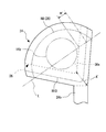
- FIG. 2 is an explanatory view of a relative positional relationship between a steering wheel and a vent hole, showing an airbag according to an embodiment of the present invention.
- 1 shows an airbag according to an embodiment of the present invention and is a front view of a vent patch.
- 1 shows an airbag according to an embodiment of the present invention and is a front view of a tether cover.
- the airbag which concerns on one Embodiment of this invention is shown, (A) is a front view of a vent cover, (B) is a front view of a patch member.
- FIG. 1 It is a front view of the vent cover of the state which showed the airbag which concerns on one Embodiment of this invention, and attached the patch member.
- the airbag which concerns on one Embodiment of this invention is shown, (A) is sectional drawing of the principal part before inflation, (B) is a fragmentary perspective view of the principal part before inflation.
- the airbag which concerns on one Embodiment of this invention is shown, (A) is sectional drawing of the principal part of an inflated state, (B) is a fragmentary perspective view of the principal part of an inflated state. It is a disassembled perspective view of the airbag which concerns on the modification of one Embodiment of this invention.
- the airbag which concerns on the modification of one Embodiment of this invention is shown, (A) is a disassembled perspective view of the principal part, (B) is a front view of the principal part.
- the airbag which concerns on the modification of one Embodiment of this invention is shown, (A) is a front view of a vent cover, (B) is a front view of a patch member. It is the front view of the vent cover of the state which showed the airbag which concerns on the modification of one Embodiment of this invention, and attached the patch member.
- the airbag which concerns on the modification of one Embodiment of this invention is shown, (A) is sectional drawing of the principal part before inflation, (B) is sectional drawing of the principal part of an expanded state, (C) is the essential part of an expanded state It is a fragmentary perspective view of a part. It is effect
- the airbag which concerns on the application example of the modification of one Embodiment of this invention is shown, (A) is a disassembled perspective view of the principal part, (B) is a front view of the principal part.
- FIG. 1 is an exploded perspective view of an airbag according to an embodiment of the present invention
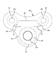
- FIG. 2 shows an airbag according to an embodiment of the present invention, a front view of an assembled state of main parts
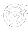
- FIG. FIG. 4 shows the airbag according to the embodiment, and is an explanatory diagram of the relative positional relationship between the steering wheel and the vent hole
- FIG. 4 shows the airbag according to the embodiment of the present invention, the front view of the vent patch
- FIG. 6 is a front view of a tether cover
- FIG. 6 shows an airbag according to an embodiment of the present invention
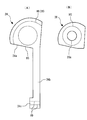
- FIG. 6 (A) is a front view of a vent cover
- FIG. 6 (A) is a front view of a vent cover
- FIG. 6 (B) Is a front view of the patch member
- FIG. 8 shows an airbag according to an embodiment of the present invention
- FIG. 8 (A) is a cross-sectional view of a main part before inflation
- FIG. 8 (B) is a main part before inflation
- FIG. 9 is a partial perspective view
- FIG. 9 shows an airbag according to an embodiment of the present invention.
- A) is a sectional view of a main part of the expanded state
- FIG. 9 (B) is a partial perspective view of the main part of the expanded state, a.
- the airbag 10 has a substantially perfect circle-shaped front panel 12 as a first panel located on the occupant facing side, and is positioned on the non-occupant facing side, having substantially the same diameter as the front panel 12. And a rear panel 14 as a second panel, and the peripheral portion thereof is joined by sewing or the like to constitute a bag-like airbag body 16.
- the front panel 12 serving as an occupant-facing surface constitutes a surface that faces (confronts) the occupant in a state where the airbag body 16 is inflated and deployed, that is, a front surface (occupant reference) where the occupant actually contacts.
- the rear panel 14 constitutes a surface excluding the front panel 12 in the three-dimensional shape of the airbag body 16 when inflated and deployed in a bag shape, and includes a side surface such as a side surface (side panel or the like) depending on the three-dimensional shape. .
- the front panel 12 is provided with an expansion control member 18 near the center.
- the expansion control member 18 is integrally formed with a joining portion 18a joined to the center of the front panel 12 by sewing H1 (shown only by a two-dot chain line in FIG. 1) and a belt-like regulating portion 18b extending from the joining portion 18a. I have.
- a substantially triangular vent patch 20 and a tether cover 22 are provided on the inner surface of the rear panel 14.
- a vent cover 24 and a patch member 26 are provided on the outer surface of the rear panel 14.
- an inflator insertion hole 14a is formed near the center of the rear panel 14.
- a pair of vent holes 14b are formed in the rear panel 14 from the center to the upper (front) side of the vehicle body in the vehicle body installation state (steering wheel installation state).
- the vent hole 14b is formed so as to have an opening center in the radial direction from the center of the rear panel 14.
- the vent hole 14b extends along a center line (0 o'clock direction) extending in the longitudinal direction of the vehicle body of the steering wheel S.
- it is formed to be symmetrical in the direction of 2 o'clock and 10 o'clock on the basis of the clock short hand.
- the vent hole 14b is formed at the center of the rear panel 14, that is, at a position close to the inflator 30 of the inflator device, and is set so that exhaust can be performed from the initial stage of deployment.
- the pair of vent holes 14b are arranged in a space portion inside the wheel rim R of the steering wheel S and avoiding the spokes P extending from the vicinity of the center of the steering wheel S toward the wheel rim R.
- the vent hole 14b is disposed at a position where interference (overlap) between the opened air grid (not shown) formed in the steering wheel S and the vent hole 14b can be avoided.
- a pair of slits 14c are formed at positions close to the vent holes 14b.
- the vent patch 20 is formed of a cloth body made of the same material as that of the front panel 12 and the rear panel 14, and is formed in a substantially triangular shape with each corner portion being arc-shaped as shown in FIG.
- the vent patch 20 includes a second inflator insertion hole 20a that matches the inflator insertion hole 14a, a pair of vent holes 20b that matches the vent hole 14b, and a pair of slits 20c that match the slits 14c. ing.
- the vent patch 20 is joined to the rear panel 14 by sewing H2, H3, and H4 in an annular shape (perfect circle) so as to surround the second inflator insertion hole 20a, for example.
- the vent patch 20 is joined to the rear panel 14 by sewing H5 in an annular shape (perfect circle) so as to surround the vent hole 20b. Further, the vent patch 20 extends so as to straddle the pair of slits 20c, and is joined by parallel sewing H6 and H7 so as to sandwich the slit 20c.
- the tether cover 22 is formed of a cloth body made of the same material as the front panel 12 and the rear panel 14, and as shown in FIG. 5, extends in the longitudinal direction of the vehicle body with a third inflator insertion hole 22a coinciding with the inflator insertion hole 14a. And a slit 22b located on the center line (0 o'clock direction).
- the tether cover 22 is formed in a different shape so as to avoid the vent hole 20b, and the slit 22b is formed so as to be positioned between the pair of slits 20c.
- the tether cover 22 is joined to the rear panel 14 integrally with the vent patch 20 (sewing H2, H3, H6, H7).
- the tether cover 22 covers the slit 20c of the vent patch 20 at both ends thereof, and the sealing performance is improved by closing the communication state with the outside through the slit 14c of the rear panel 14.
- the vent cover 24 includes a fan-shaped cover 24a, a belt-like tether 24b extending from the cover 24a, a joint piece 24c positioned at the tip of the tether 24b and wider than the tether 24b, It has.
- the vent cover 24 is provided individually corresponding to each vent hole 14b.
- the vent cover 24 is provided symmetrically to each other as shown in FIG. 1 by using the vent cover 24 having the same shape, size, and the like (inverted in the apparent mounting state).
- the pair of vent holes 14b are provided symmetrically with respect to the center line (0 o'clock direction).
- the pair of vent covers 24 are disposed symmetrically with respect to the center line of the rear panel 14 (airbag body 16).
- the arc-shaped peripheral edge portion of the cover 24a is joined to the rear panel 14 by sewing H8, and the hinge portion 28 is configured by the sewing H8.
- the hinge portion 28 is formed on the downstream side in the introduction direction (injection direction) of the pressure gas injected from the inflator 30 disposed at the center of the rear panel 14, that is, on the outer peripheral side of the rear panel 14. Therefore, it is preferable that the arc center of the hinge portion 28 is located on the extended line connecting the center of the rear panel 14 and the center of the vent hole 14b.
- the joining piece 24c is joined by sewing H9.
- the length of the tether 24b is set so as to define the opening degree of the cover 24a with reference to the slit 22b when the joining piece 24c is joined.
- the tether 24b which is one end of the vent cover 24, passes through the slit 20c and the slit 22b, so that the cloth body of the slit 20c is not easily stretched by the pressure gas ejected from the inflator 30, thereby reducing gas leakage.
- the patch member 26 is formed in a fan shape, and an opening 26a having a diameter smaller than the opening diameter of the vent hole 14b is formed at the center thereof.
- the patch member 26 is joined to the cover 24a by sewing H5 so as to surround the opening 26a.
- the cover 24a and the patch member 26 are positioned along the rear panel 14 when the inflator 30 is not in operation.
- the inflator 30 When the inflator 30 is activated and the pressure gas is supplied to the inside of the airbag body 16, a part of the pressure gas is about to be discharged from the vent hole 14b.
- the restricting portion 18b and the tether 24b are tensioned to generate a pulling force, and the opening degree of the cover 24a is restricted.
- Part of the pressure gas is supplied between the cover 24a and the patch member 26 from the opening 26a, and the cover 24a and the patch member 26 cooperate as shown in FIGS. 9 (A) and 9 (B).
- the vent hole 14b is pressed down while forming a pressure gas storage space K between the cover 24a and the patch member 26. Therefore, in addition to the restriction of the opening degree of the cover 24a due to the pulling force of the tether 24b described above, the cover 24a and the patch member 26 expand, whereby the degree of sealing of the vent hole 14b can be maintained high.
- the overall length of the airbag body 16 with the tether 24b can define the thickness when the airbag body 16 is inflated, and the inflation and deployment of the airbag body 16 causes a pulling action on the tether 24b. 14b can be pressed in the closing direction.
- the airbag 10 of the present embodiment is formed in the bag body so that the airbag body 16 has at least the front panel 12 and the rear panel 14 in the inflated and deployed state, and the vent hole 14b is formed in the rear panel 14.
- the vent cover 24 that opens and closes the vent hole 14b is attached to the outer surface of the rear panel 14, the patch member 26 is attached to the vent cover 24, and is supplied into the airbag body 16 when the airbag body 16 is inflated and deployed.
- the vent cover 24 and the patch member 26 cooperate and expand using a part of the pressure gas to regulate the opening degree of the vent hole 14b. That is, when the pressure gas is introduced into the airbag main body 16, it tends to leak from the vent hole 14b.
- the pressure gas to be leaked is formed between the vent cover 24 and the patch member 26 from the opening 26a (specifically, on the outer peripheral side of the opening 26a and between the vent cover 24 and the patch member 26). Gas storage space K).
- the patch member 26 includes an opening 26a facing the vent hole 14b, and is joined to the vent cover 24 so as to surround the opening 26a, so that the pressure gas to leak from the vent hole 14b is opened. 26a is efficiently taken into the gas storage space K.
- the joined body of the vent cover 24 and the patch member 26 acts so as to close the vent hole 14b while inflating, so that the opening degree of the vent hole 14b can be closed or in a small open state.
- the internal pressure of the main body 16 can be kept high.
- the vent cover 24 is pushed by the pressure, the vent hole 14b is opened, the pressure gas in the airbag body 16 is released to the outside, and the occupant can be received smoothly. it can.
- the vent cover 24 includes the hinge portion 28 joined to the rear panel 14 on the downstream side in the introduction direction of the pressure gas introduced into the airbag main body 16. 16 can be received by the hinge portion 28 so as to leak from the vent hole 14b. Further, the opening of the vent cover 24 can be easily suppressed, and at the same time, the expansion by the cooperation of the vent cover 24 and the patch member 26 can be facilitated.
- the vent cover 24 is provided with a tether 24b as a regulating member that regulates the degree of opening of the vent cover 24 on the side opposite to the hinge portion 28, so that cooperation with the patch member 26 is achieved.
- a tether 24b as a regulating member that regulates the degree of opening of the vent cover 24 on the side opposite to the hinge portion 28, so that cooperation with the patch member 26 is achieved.
- FIG. 10 to 15 show an airbag according to a modification of one embodiment of the present invention
- FIG. 10 shows an exploded perspective view of the airbag according to the modification
- FIG. 11 shows an airbag according to the modification
- FIG. (A) is an exploded perspective view of the main part
- FIG. 11 (B) is a front view of the main part
- FIG. 12 shows an airbag according to a modification
- FIG. 12 (A) is a front view of the vent cover
- FIG. B) is a front view of the patch member
- FIG. 13 shows an airbag according to a modification, a front view of the patch member attached to the vent cover, FIG. 14 shows an airbag according to the modification, and FIG. ) Is a cross-sectional view of the main part before expansion, FIG. 14B is a cross-sectional view of the main part in the expanded state, FIG. 14C is a partial perspective view of the main part in the expanded state, and FIG. It is action explanatory drawing which shows a bag. 10 to 15, the same reference numerals are given to the same components as those in the above embodiment, and the description thereof is omitted.
- a patch member 36 is provided between the rear panel 14 and the vent cover 24 (cover 24a).
- the patch member 36 is a substantially V-shaped belt-like member along the other two sides of the cover 24a excluding the arc-shaped side joined to the rear panel 14 by sewing H8.
- the patch member 36 is joined to the cover 24a by the other two sides of the cover 24a and the sewing H10 so that the inner edge side (the vent hole 14b side) is a free end.
- the angle of the inner angle formed by the two sides of the patch member 36 is arbitrary depending on the shape of the cover 24a. Further, the patch member 36 has an opening 36a on the inner angle side of the other two sides where the vent hole 14b is located.
- the inner edge of the patch member 36 and the opening edge of the vent hole 14b may be tangentially overlapped, or as shown in FIG. A part of the inner edge side of the member 36 may enter the opening of the vent hole 14b, or the entire patch member 36 may be separated from the vent hole 14b as shown in FIG. In other words, the same patch member 36 can be used regardless of the size of the vent hole 14b.
- the inflator 30 When the inflator 30 is activated and the pressure gas is supplied to the inside of the airbag body 16, a part of the pressure gas is about to be discharged from the vent hole 14b.
- a part of the pressure gas is supplied between the cover 24a and the patch member 36 through the opening 36a, and as shown in FIGS. 14B and 14C, the cover 24a and the patch member 36 Are expanded in cooperation with each other, and the opening degree is regulated so that the vent hole 14b is closed or in a small open state.
- the opening degree of the cover 24a is regulated by the pulling force of the tether 24b, and the sealing degree of the vent hole 14b can be kept high by pressing the cover 24a toward the vent hole 14b.
- the thickness of the airbag main body 16 can be defined by the total length with the tether 24b, and a pulling action is generated in the tether 24b by the inflation and deployment of the airbag main body 16, and the vent cover 24 is closed by the vent hole 14b. Can be pressed in the direction.
- the patch member 36 has less exhaust resistance of the pressure gas inside the airbag body 16 when the occupant comes into contact, and can efficiently exhaust air from the vent hole 14b. Moreover, since most of the patch members 36 do not directly interfere with the vent holes 14b, the patch members 36 do not interfere with the exhaust and can improve the robustness during the exhaust.
- the vent cover 24 at the time of gas exhaust opens, for example, around a line connecting the vicinity of both ends of the sewing H8 with the rear panel 14 (see a virtual line L in FIG. 15). For this reason, the distance W ′ from the outer edge to the inner edge of the belt-like patch member 36 in the direction along the center (imaginary line L) is compared with the distance W in the case of the patch member 26 (see FIG. 7). Can be shortened.
- the diameter of the opening 26a of the patch member 26 is smaller than the diameter of the vent hole 14b.
- part of the inner edge of the patch member 36 enters the vent hole 14b (FIG. 14), is it in contact with the opening edge of the vent hole 14b (FIG. 11), or is it separated from the vent hole 14b? (FIG. 15), the distance W ′ in the case of the patch member 36 is shorter than the distance W in the case of the patch member 26.
- the patch member 36 is a small exhaust that allows the vent cover 24 to open easily with respect to the pressure gas that enters the space K (see FIG. 14B) during expansion by the cooperation of the rear panel 14 and the cover portion 24a. It can be a resistance.
- the exhaust of the pressure gas from the vent hole 14b through the space K from the inside of the airbag body 16 can be performed smoothly.
- the area ratio between the opening area of the vent hole 14b and the entire area of the patch member 36 is smaller than the area ratio of the opening area of the vent hole 14b and the entire area of the patch member 26. For this reason, the material cost of the patch member 36 can be reduced as compared with the patch member 26.
- the patch member 36 has a distance A in the case of the patch member 26 (FIG. 7) even at a distance A ′ from the boundary portion between the cover 24 a and the tether 24 b to the inner edge of the nearest patch member 36. (See below). Accordingly, the exhaust resistance of the patch member 36 to the pressure gas in the vicinity of the pulling action point (the boundary portion between the cover 24a and the tether 24b) that restricts the opening degree of the cover 24a can be reduced. As a result, the pressure gas is efficiently exhausted from the vicinity of the pulling point, which is also near the center of the arc of the hinge portion 28 (sewing H8).
- an internal angle ⁇ formed by a line segment connecting the center Q of the vent hole 14b and both ends of the sewing H8 forming the hinge portion 28 is set to 180 ° or less. Accordingly, a wide opening area of the vent hole 14b facing the portion located outside the line connecting the both ends of the hinge portion 28, that is, on the opposite side of the cover 24a of the vent cover 24 from the hinge portion 28 is secured. Therefore, the exhaust efficiency of the pressure gas from the vent hole 14b can be ensured high.
- the structure of the airbag 10 using the patch members 26 and 36 of the present invention is applied to the airbag 10 of the airbag apparatus for the driver assembled to the steering wheel in the above embodiment and the modification.
- the present invention is not limited to this. That is, the configuration of the airbag 10 using the patch members 26 and 36 according to the present invention includes various airbag devices such as a side airbag device, in addition to an airbag of a passenger seat airbag device including a side panel (side surface).
- the airbag can be applied to all airbags having vent holes, such as
Landscapes
- Engineering & Computer Science (AREA)
- Mechanical Engineering (AREA)
- Air Bags (AREA)
Description
本発明は、自動車等の衝突時に乗員の安全を確保するためのエアバッグ及びそれを利用したエアバッグ装置に関する。
従来、自動車の衝突、横転などの緊急時にインフレータが作動し、このインフレータから噴出された圧力ガスによって袋体に形成されたエアバッグが折り畳まれた状態から膨張展開し、乗員を拘束するエアバッグ装置が知られている。
エアバッグ装置に用いられるエアバッグには、膨張展開状態において少なくとも第1パネルと第2パネルとを有するように袋体に形成されたエアバッグ本体と、第2パネルに形成されたベントホールと、を備えている。このベントホールは、膨張展開したエアバッグ本体に乗員が接触したときに、ベントホールを介してエアバッグ本体の内部から圧力ガスを流出させる。これにより、乗員をエアバッグ本体によって円滑に受け止めることができる。
近年では、エアバッグ本体の内圧が所定以上となるまではベントホールが閉又は小開度となり、エアバッグの内圧が所定以上となるとともにエアバッグに乗員が接触したときにベントホールが開又は大開度となるように構成された、エアバッグが提案されている(例えば、特許文献1及び特許文献2参照)。
特許文献1に開示の技術は、エアバッグの膨張展開時に、ベントホールの外側に設けた開閉部材を、エアバッグ内部を通したテザーによって開閉する。したがって、ベントホールを開閉する際に、テザーの動作挙動が圧力ガスの影響を受けやすく、ベントホールの閉度を円滑かつ高精度に制御することが容易ではない。この結果、エアバッグ本体の内圧を高精度に確保するために、エアバッグ本体の容積を小さくしたり、インフレータから噴出される圧力ガスの噴出能力を高くするなどの複雑な設定が必要となっていた。
特許文献2に開示の技術は、ベントホールの開度を調整するための専用の開閉装置を必要とする。この結果、上記開閉装置を設置するためのスペース確保のためにエアバッグ装置の大型化、さらにはエアバッグ装置の高コスト化を招く。
本発明の目的は、複雑な設定を行うことなく、比較的簡素かつ低コストな構造で、ベントホールの閉度を円滑かつ高精度に制御できるエアバッグ及びエアバッグ装置を提供することを目的とする。
上記課題を解決するため、第1発明のエアバッグは、膨張展開状態において少なくとも乗員対向側の第1パネルと非乗員対向側の第2パネルとを有するように袋体に形成されたエアバッグ本体と、前記第2パネルに形成されたベントホールと、前記第2パネルの外面に取り付けられて前記ベントホールを開閉するベントカバーと、前記第2パネルと前記ベントカバーとの間で前記ベントカバーに接合されて前記ベントホールと連通する開口を有するパッチ部材と、を備えることを特徴とする。
第1発明のエアバッグは、エアバッグ本体が膨張展開状態において少なくとも第1パネルと第2パネルとを有するように袋体に形成され、ベントホールが第2パネルに形成され、ベントホールを開閉するベントカバーが第2パネルの外面に取り付けられている。
ここで、エアバッグ本体は、自動車の衝突、横転などの緊急時にインフレータが作動し、このインフレータから噴出される圧力ガスによって袋体に形成されたエアバッグが折り畳まれた状態から袋状に膨張展開し、膨張展開したエアバッグ本体に乗員が接触したときに、乗員を受け止める(拘束する)ことができる。
また、ここでの第1パネルとは、エアバッグ本体が膨張展開した状態において乗員と対向(対峙)する面、すなわち、乗員が実際に接触する正面(乗員基準)を構成するパネルを示す。また、第2パネルとは、袋状に膨張展開した際のエアバッグ本体の立体形状における第1パネル以外の面を示し、その立体形状によって正面の裏面側となる底面又は底面及び側面等の複数面を示す。
さらに、さらに、第1発明のエアバッグは、第2パネルとベントカバーとの間に位置するようにパッチ部材がベントカバーに接合されており、このパッチ部材にはベントホールと連通する開口が設けられている。そして、エアバッグ本体が膨張展開する際にエアバッグ本体内に供給される圧力ガスの一部を利用して、ベントホールの開度を規制する。すなわち、圧力ガスがエアバッグ本体の内部に導入されると、ベントホールから放出されようとする。そこで、その放出されようとする圧力ガスがベントカバーとパッチ部材との間(具体的には上記開口の外周側でかつベントカバーとパッチ部材との間に形成されるガス貯留用の空間)に取り込まれる。このとき、ベントホールと連通する開口よりも外側でベントカバーとパッチ部材との接合体が、膨張しつつベントホールを塞ぐように作用し、ベントホールの開度を閉若しくは小開状態とすることができる。これにより、エアバッグ本体の内圧を高く維持することができる。
一方、乗員がエアバッグ本体に当接すると、その当接圧力によってベントカバーが押し出され、ベントホールを開き、エアバッグ本体内の圧力ガスを外部へと排気し、乗員を円滑に受け止めることができる。
第2発明のエアバッグは、第1発明のエアバッグにおいて、前記ベントカバーは、一方側に、前記第2パネルと接合されたヒンジ部を備えており、他方側に、前記ベントカバーの開放度を規制する規制部材を備えていることを特徴とする。
第2発明のエアバッグによれば、第2パネルと接合されたヒンジ部がベントカバーの一方側(例えば、エアバッグ本体に導入される圧力ガスの導入方向下流側)に設けられている。これにより、エアバッグ本体に導入されてベントホールから漏れようとする圧力ガスをヒンジ部で受け止めることができ、ベントカバーの開きを抑制し易くすると同時にパッチ部材との協働による膨張も容易とすることができる。また、前記ベントカバーの開放度を規制する規制部材がベントカバーの他方側(すなわち上記ヒンジ部と逆側)に設けられている。これにより、パッチ部材との協働により膨張している際に、パッチ部材をベントホールに押さえ付けることができ、ベントホールの密閉度を容易に高く確保することができる。
第3発明のエアバッグは、第1発明又は第2発明のエアバッグにおいて、前記パッチ部材は、前記開口としての前記ベントホールと対向する穴によって前記ベントホールと連通するとともに、前記穴の外周側を取り巻く部位において前記ベントカバーに接合されていることを特徴とする。
さらに、第3発明のエアバッグは、パッチ部材の開口がベントホールと対向する穴とされており、しかも開口の外周側を取り巻く部位においてパッチ部材がベントカバーに接合されている。そして、エアバッグ本体が膨張展開する際にエアバッグ本体内に供給される圧力ガスの一部を利用して、ベントホールの開度を規制する。すなわち、圧力ガスがエアバッグ本体の内部に導入されると、ベントホールから放出されようとする。そこで、その放出されようとする圧力ガスがベントカバーとパッチ部材との間(具体的には上記開口の外周側でかつベントカバーとパッチ部材との間に形成されるガス貯留用の空間)に取り込まれる。このとき特に、ベントホールと対向する開口を取り巻くようにパッチ部材がベントカバーに接合されていることにより、ベントホールから漏れようとする圧力ガスが、開口から効率良く上記ガス貯留用の空間に取り込まれる。この結果、それらベントカバーとパッチ部材との接合体が、膨張しつつベントホールを塞ぐように作用し、ベントホールの開度を閉若しくは小開状態とすることができる。これにより、エアバッグ本体の内圧を高く維持することができる。
第4発明のエアバッグは、第2発明のエアバッグにおいて、前記ベントカバーは、前記ベントホールよりも大きい略扇形状とされるとともに、その一辺の円弧状部分が前記ヒンジ部とされ、前記パッチ部材は、前記ベントカバーの他の二辺に沿う略V字形状の帯状部材とされてその内角側が前記開口とされ、前記帯状部材の外縁寄りを前記ベントカバーと接合しかつ内縁側を自由端としたことを特徴とする。
第4発明のエアバッグによれば、略扇形状のベントカバーのうち、ヒンジ部を除く残余の縁部となる二辺に略V字形状のパッチ部材がベントカバーに接合され、このパッチ部材のV字形状の二辺に鋭角側で挟まれている内側部分(内角側)を開口としてベントホールと連通させるとともに、ベントカバーとパッチ部材との協働によりベントホールから放出されようとする圧力ガスをベントカバーとパッチ部材との間に取り入れることができる。したがって、ヒンジ部を除く残余の縁部となる二辺に対応する部分にのみ、小さい略V字形状パッチ部材を配置すれば良く、パッチ部材の材料コストを削減することができる。
第5発明のエアバッグは、第4発明のエアバッグにおいて、前記ベントカバーは、前記ベントホールの中心と前記ヒンジ部の両端とを結ぶ線分でなす内角が180°以下となるように、前記第2パネルと接合されていることを特徴とする。
第5発明のエアバッグによれば、ヒンジ部の両端間を結ぶ線よりも外側(ヒンジ部とは反対の前記帯状部材側)に位置するベントホールの開口面積を広く確保することができるため、ベントホールのからの圧力ガスの排気効率を高く確保することができる。
第6発明のエアバッグ装置は、第1発明のエアバッグと、前記エアバッグに圧力ガスを供給するインフレータと、を備えていることを特徴とする。
第6発明のエアバッグ装置によれば、エアバッグに圧力ガスを供給するインフレータを備えたエアバッグ装置のベントホールに対してベントカバーとパッチ部材とを適用することが可能となる。
本発明のエアバッグ及びエアバッグ装置は、複雑な設定を行うことなく、比較的簡素かつ低コストな構造で、ベントホールの閉度を円滑かつ高精度に制御することができる。この結果、エアバッグの膨張展開が完了するまでの間の内圧を高く保持しつつ、乗員がエアバッグに接触した後の圧力ガスを排気しやすくすることができる。
次に、本発明の一実施形態に係るエアバッグ及びエアバッグ装置について、図面を参照して説明する。
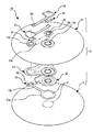
図1は本発明の一実施形態に係るエアバッグの分解斜視図、図2は本発明の一実施形態に係るエアバッグを示し、要部の組み付け状態の正面図、図3は本発明の一実施形態に係るエアバッグを示し、ステアリングホイールとベントホールとの相対位置関係の説明図、図4は本発明の一実施形態に係るエアバッグを示し、ベントパッチの正面図、図5は本発明の一実施形態に係るエアバッグを示し、テザーカバーの正面図、図6は本発明の一実施形態に係るエアバッグを示し、図6(A)はベントカバーの正面図、図6(B)はパッチ部材の正面図、図8は本発明の一実施形態に係るエアバッグを示し、図8(A)は膨張前の要部の断面図、図8(B)は膨張前の要部の部分斜視図、図9は本発明の一実施形態に係るエアバッグを示し、図9(A)は膨張状態の要部の断面図、図9(B)は膨張状態の要部の部分斜視図、である。
図1及び図2において、エアバッグ10は、乗員対向側に位置する第1パネルとしての略真円形状のフロントパネル12と、フロントパネル12と略同一径とされて非乗員対向側に位置する第2パネルとしてのリヤパネル14と、を備え、その周縁部を縫製等によって接合することで袋状のエアバッグ本体16を構成している。なお、乗員対向面としてのフロントパネル12は、エアバッグ本体16が膨張展開した状態において乗員と対向(対峙)する面、すなわち、乗員が実際に接触する正面(乗員基準)を構成する。また、リヤパネル14は、袋状に膨張展開した際のエアバッグ本体16の立体形状におけるフロントパネル12を除く面を構成し、その立体形状によっては、側面(サイドパネル等)等の側面を含むものとする。
フロントパネル12には、中央付近に膨張制御部材18が設けられている。この膨張制御部材18は、フロントパネル12の中央に縫製H1(図1にのみ二点鎖線で図示)により接合される接合部18aと、接合部18aから延びる帯状の規制部18bと、を一体に備えている。
リヤパネル14の内面には、略三角形状のベントパッチ20と、テザーカバー22と、が設けられている。また、リヤパネル14の外面には、ベントカバー24と、パッチ部材26と、が設けられている。
リヤパネル14の中心付近にはインフレータ挿入穴14aが形成されている。リヤパネル14には、その中心から車体設置状態(ステアリングホイール設置状態)において車体上方(前方)側に一対のベントホール14bが形成されている。ベントホール14bは、リヤパネル14の中心から放射方向に開口中心を有するように形成されており、例えば、図3に示すように、ステアリングホイールSの車体前後方向に延びる中心線(0時方向)に対して時計短針基準で2時と10時の方向に対称となるように形成されている。なお、ベントホール14bは、リヤパネル14の中心、すなわち、インフレータ装置のインフレータ30に対して近接した位置に形成されており、展開初期から排気が可能となるように設定されている。この際、一対のベントホール14bは、ステアリングホイールSのホイールリムRよりも内側で、ステアリングホイールSの中心付近からホイールリムRに向かって伸びるスポークPを避けた空間部分に配置される。さらに、ベントホール14bは、ステアリングホイールSに形成された開放後のエアバッグリッド(図示せず)とベントホール14bとの干渉(重なり)を避けることができる位置に配置されている。リヤパネル14には、各ベントホール14bに近接した位置に一対のスリット14cが形成されている。
ベントパッチ20は、フロントパネル12及びリヤパネル14と同じ材質の布体から形成されており、図4に示すように、各角部を円弧状とした略三角形状に形成されている。ベントパッチ20は、上述したインフレータ挿入穴14aと一致する第2インフレータ挿入穴20aと、ベントホール14bと一致する一対のベントホール20bと、各スリット14cに一致する一対のスリット20cと、が形成されている。ベントパッチ20は、例えば、第2インフレータ挿入穴20aを取り巻くように環状(真円)にリヤパネル14に縫製H2,H3,H4により接合されている。また、ベントパッチ20は、ベントホール20bを取り巻くように環状(真円)にリヤパネル14に縫製H5により接合されている。さらに、ベントパッチ20は、一対のスリット20cに跨るように延在されるとともに、スリット20cを挟むように並行な縫製H6,H7によって接合されている。
テザーカバー22は、フロントパネル12及びリヤパネル14と同じ材質の布体から形成されており、図5に示すように、インフレータ挿入穴14aと一致する第3インフレータ挿入穴22aと、車体前後方向に延びる中心線(0時方向)上に位置するスリット22bと、が形成されている。なお、テザーカバー22は、ベントホール20bを避けるように異型に形成されており、スリット22bは一対のスリット20cの間に位置するように形成されている。テザーカバー22は、ベントパッチ20と一体にリヤパネル14に接合(縫製H2,H3,H6,H7)されている。テザーカバー22は、その両端部でベントパッチ20のスリット20cを覆っており、リヤパネル14のスリット14cを介して外部との連通状態を塞ぐことで密閉性を向上している。
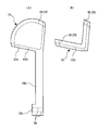
ベントカバー24は、図6(A)に示すように、扇状のカバー24aと、カバー24aから延びる帯状のテザー24bと、テザー24bの先端に位置してテザー24bよりも幅広の接合片24cと、を備えている。なお、ベントカバー24は、各ベントホール14bに対応して個々に設けられている。この際、ベントカバー24は、その形状や大きさ等を同一(見掛け上の取り付け状態で表裏反転)にしたものを用いることにより、図1に示すように、互いに対称に設けられる。本実施の形態では、一対のベントホール14bを、中心線(0時方向)に対して対称に設けている。したがって、一対のベントカバー24は、リヤパネル14(エアバッグ本体16)の中心線に対しても対称に配置されている。ベントカバー24は、カバー24aの円弧状周縁部が縫製H8によってリヤパネル14に接合されており、その縫製H8によってヒンジ部28を構成している。ここで、ヒンジ部28は、リヤパネル14の中心に配置されるインフレータ30から噴射される圧力ガスの導入方向(噴射方向)下流側、すなわち、リヤパネル14の外周側に形成されている。したがって、ヒンジ部28の円弧中心は、リヤパネル14の中心とベントホール14bの中心とを結ぶ線の延長線上に位置するのが好ましい。テザー24bは、スリット14c及びスリット20cに挿入された後、ベントパッチ20とテザーカバー22との間(縫製H6と縫製H7との間)を経由してスリット22bから引き出された後、各両端の接合片24cが縫製H9によって接合されている。テザー24bの長さは、その接合片24cを接合したときのスリット22bを基準としてカバー24aの開度を規定するように設定されている。また、一対のテザー24bは、膨張制御部材18の規制部18bの先端と縫製H9によって接合することによって、一対のテザー24bと規制部18bの長さに応じてエアバッグ本体16が膨張展開したときのエアバッグ本体16の厚さが規定される。また、ベントカバー24の一端であるテザー24bは、スリット20c及びスリット22bを通すことで、インフレータ30から噴出された圧力ガスによってスリット20cの布体が伸び難く、ガス漏れを軽減している。
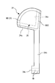
パッチ部材26は、図6(B)に示すように、扇状に形成されており、その中心にはベントホール14bの開口径よりも小径な開口26aが形成されている。本実施の形態では、図7に示すように、パッチ部材26は開口26aを取り巻くように縫製H5によってカバー24aに接合されている。
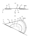
上記の構成において、図8(A),(B)に示すように、インフレータ30が作動していない収納状態では、カバー24aとパッチ部材26とはリヤパネル14に沿うように位置している。
インフレータ30が作動して、その圧力ガスがエアバッグ本体16の内部に供給されると、その一部がベントホール14bから外部に放出されようとする。ここで、エアバッグ本体16が膨張するにつれて規制部18bとテザー24bとが緊張して引っ張り力が発生し、カバー24aの開度が規制される。また、圧力ガスの一部は、開口26aからカバー24aとパッチ部材26との間に供給され、図9(A),(B)に示すように、カバー24aとパッチ部材26とが協働して膨張し、カバー24aとパッチ部材26との間に圧力ガス貯留用の空間Kを形成しつつ、ベントホール14bを押さえ込む。したがって、上述したテザー24bの引っ張り力によるカバー24aの開度規制に加えて、カバー24aとパッチ部材26とが膨張することにより、ベントホール14bの密閉度を高く維持することができる。
また、エアバッグ本体16の膨張展開時の厚さを規定する膨張制御部材18の他端(規制部18b)とテザー24bの両端(接合片24c)とを接合したことにより、これら規制部18bとテザー24bとの全体の長さでエアバッグ本体16の膨張時の厚さを規定することができるとともに、エアバッグ本体16の膨張展開によってテザー24bに引っ張り作用が発生し、ベントカバー24をベントホール14bの閉じ方向に押さえ付けることができる。
以上説明したように、本実施形態のエアバッグ10は、エアバッグ本体16が膨張展開状態において少なくともフロントパネル12とリヤパネル14とを有するように袋体に形成され、ベントホール14bがリヤパネル14に形成され、ベントホール14bを開閉するベントカバー24がリヤパネル14の外面に取り付けられ、パッチ部材26がベントカバー24に取り付けられ、エアバッグ本体16が膨張展開する際にエアバッグ本体16内に供給される圧力ガスの一部を利用してベントカバー24とパッチ部材26とが協働して膨張することでベントホール14bの開度を規制する。すなわち、圧力ガスがエアバッグ本体16の内部に導入されると、ベントホール14bから漏れ出そうとする。
そこで、その漏れ出そうとする圧力ガスを開口26aからベントカバー24とパッチ部材26との間(具体的には、上記開口26aの外周側でかつベントカバー24とパッチ部材26との間に形成されるガス貯留用の空間K)に取りこむ。このとき特に、パッチ部材26は、ベントホール14bと対向する開口26aを備えるとともに、開口26aを取り巻くようにベントカバー24に接合されていることにより、ベントホール14bから漏れようとする圧力ガスが開口26aから効率良く上記ガス貯留用の空間Kに取り込まれる。これらの結果、ベントカバー24とパッチ部材26との接合体が膨張しつつベントホール14bを塞ぐように作用するので、ベントホール14bの開度を閉若しくは小開状態とすることができ、エアバッグ本体16の内圧を高く維持することができる。
なお、一対のテザー24bの接合片24cと規制部18bの先端とを接合することによって、エアバッグ本体16の膨張展開時にテザー24bに引っ張り作用が発生し、ベントカバー24をベントホール14bの閉じ方向に押さえ付けることができる。また、一対のテザー24bの接合片24cを互いに接合することで、一対のベントホール14bが同時に動作をするため、一対のベントホール14bの開度を均一化することができる。この際、膨張制御部材18とテザーカバー22のスリット22bとが中心(0時方向)に設けられていることから、互いに対象であることと相俟って、一対のベントホール14bの開度をより一層容易に均一化することができる。
一方、乗員がエアバッグ本体16に当接すると、その圧力によってベントカバー24が押され、ベントホール14bを開き、エアバッグ本体16内の圧力ガスを外部へと逃がし、乗員を円滑に受け止めることができる。
また、本実施形態では特に、ベントカバー24は、エアバッグ本体16の内部に導入される圧力ガスの導入方向下流側にリヤパネル14と接合されたヒンジ部28を備えていることにより、エアバッグ本体16に導入されてベントホール14bから漏れようとする圧力ガスをヒンジ部28で受け止めることができる。また、ベントカバー24の開きを抑制し易くすると同時に、ベントカバー24とパッチ部材26との協働による膨張も容易とすることができる。
また、本実施形態では特に、ベントカバー24には、ヒンジ部28と逆側にベントカバー24の開放度を規制する規制部材としてのテザー24bが設けられていることにより、パッチ部材26との協働により膨張している際に、パッチ部材26をベントホール14bに押さえ付けることができ、ベントホール14bの密閉度を容易に高く確保することができる。
<変形例>
ところで、上記実施の形態では、ベントホール14bよりも小径な穴から開口26aを形成したパッチ部材26を示したが、開口26aは穴で無くても良い。図10~図15は本発明の一実施形態の変形例に係るエアバッグを示し、図10は変形例に係るエアバッグの分解斜視図、図11は変形例に係るエアバッグを示し、図11(A)は要部の分解斜視図、図11(B)は要部の正面図、図12は変形例に係るエアバッグを示し、図12(A)はベントカバーの正面図、図12(B)はパッチ部材の正面図、図13は変形例に係るエアバッグを示し、ベントカバーにパッチ部材を取り付けた状態の正面図、図14は変形例に係るエアバッグを示し、図14(A)は膨張前の要部の断面図、図14(B)は膨張状態の要部の断面図、図14(C)は膨張状態の要部の部分斜視図、図15は変形例に係るエアバッグを示す作用説明図である。なお、図10~図15中において、上記実施の形態と同一の構成には同一の符号を付してその説明を省略する。
ところで、上記実施の形態では、ベントホール14bよりも小径な穴から開口26aを形成したパッチ部材26を示したが、開口26aは穴で無くても良い。図10~図15は本発明の一実施形態の変形例に係るエアバッグを示し、図10は変形例に係るエアバッグの分解斜視図、図11は変形例に係るエアバッグを示し、図11(A)は要部の分解斜視図、図11(B)は要部の正面図、図12は変形例に係るエアバッグを示し、図12(A)はベントカバーの正面図、図12(B)はパッチ部材の正面図、図13は変形例に係るエアバッグを示し、ベントカバーにパッチ部材を取り付けた状態の正面図、図14は変形例に係るエアバッグを示し、図14(A)は膨張前の要部の断面図、図14(B)は膨張状態の要部の断面図、図14(C)は膨張状態の要部の部分斜視図、図15は変形例に係るエアバッグを示す作用説明図である。なお、図10~図15中において、上記実施の形態と同一の構成には同一の符号を付してその説明を省略する。
図10及び図11に示すように、リヤパネル14とベントカバー24(カバー24a)との間には、パッチ部材36が設けられている。パッチ部材36は、縫製H8によってリヤパネル14と接合された円弧状の辺を除くカバー24aの他の二辺に沿う略V字形状の帯状部材とされている。
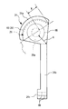
パッチ部材36は、図12及び図13に示すように、内縁側(ベントホール14b側)が自由端となるように、外縁寄りをカバー24aの上記他の二辺と縫製H10によりカバー24aに接合されている。なお、パッチ部材36の二辺による内角の角度はカバー24aの形状等により任意である。また、パッチ部材36は、ベントホール14bが位置する上記他の二辺による内角側を開口36aとしている。
この際、例えば、図11(B)に示すように、パッチ部材36の内縁とベントホール14bの開口縁とが接線状に重なっていても良いし、図14(A)に示すように、パッチ部材36の内縁側の一部がベントホール14bの開口に入り込んでいても良いし、図15に示すように、パッチ部材36の全体がベントホール14bから離れていても良い。換言すれば、パッチ部材36は、ベントホール14bの大きさにかかわらず、同じものを用いることができる。
上記のような本変形例の構成においては、インフレータ30が作動していない収納状態では、図14(A)に示すように、カバー24aとパッチ部材36とはリヤパネル14に沿うように位置している。
インフレータ30が作動して、その圧力ガスがエアバッグ本体16の内部に供給されると、その一部がベントホール14bから外部に放出されようとする。ここで、その圧力ガスの一部は、開口36aからカバー24aとパッチ部材36との間に供給され、図14(B)及び図14(C)に示すように、カバー24aとパッチ部材36とが協働して膨張し、ベントホール14bを閉若しくは小開状態となるように開度を規制する。また、テザー24bの引っ張り力により、カバー24aの開度が規制され、カバー24aをベントホール14bに向けて押さえ込むことにより、ベントホール14bの密閉度を高く維持することができる。
また、エアバッグ本体16の膨張展開時の厚さを規定する膨張制御部材18の他端(規制部18b)とテザー24bの両端(接合片24c)とを接合したことにより、これら規制部18bとテザー24bとの全体の長さでエアバッグ本体16の厚さを規定することができるとともに、エアバッグ本体16の膨張展開によってテザー24bに引っ張り作用が発生し、ベントカバー24をベントホール14bの閉じ方向に押さえ付けることができる。
この際、パッチ部材36は、乗員が接触したときのエアバッグ本体16の内部の圧力ガスの排気抵抗が少なく、ベントホール14bから効率良く排気することができる。しかも、パッチ部材36は、そのほとんどがベントホール14bと直接的には干渉していないため、排気を妨げる要因とならず、排気時のロバスト性を向上することができる。
ここで、ガス排気時のベントカバー24は、例えば、リヤパネル14との縫製H8の両端付近を結ぶ線(図15の仮想線L参照)を中心として開いていく。このため、この中心(仮想線L)に沿う方向での帯状のパッチ部材36の外側縁部から内側縁部までの距離W’は、パッチ部材26の場合の距離W(図7参照)に比べて短くすることができる。
すなわち、パッチ部材26の開口26aの直径はベントホール14bの直径よりも小径としている。一方、パッチ部材36は、その内縁の一部が、ベントホール14bに入り込んでいる(図14)か、ベントホール14bの開口縁部と接しているか(図11)、ベントホール14bから離れているか(図15)、の何れかであるため、パッチ部材36の場合の距離W’はパッチ部材26の場合の距離Wよりも短くなる。このため、パッチ部材36は、リヤパネル14とカバー部24aとの協働による膨張時の空間K(図14(B)参照)に入り込む圧力ガスに対して、ベントカバー24が開き易い、少な目の排気抵抗とすることができる。したがって、エアバッグ本体16の内部から空間Kを経由してのベントホール14bからの圧力ガスの排気をスムーズに行うことができる。しかも、ベントホール14bの開口面積とパッチ部材26の全体面積との面積比に対して、ベントホール14bの開口面積とパッチ部材36の全体面積との面積比は小さい。このため、パッチ部材36の材料コストをパッチ部材26よりも削減することができる。
さらに、図15に示すように、パッチ部材36は、カバー24aとテザー24bとの境界部分から直近のパッチ部材36の内縁までの距離A’においても、パッチ部材26の場合の距離A(図7参照)よりも短くすることができる。したがって、カバー24aの開度を規制する引っ張り作用点(カバー24aとテザー24bとの境界部分)付近における圧力ガスに対するパッチ部材36の排気抵抗が小さくすることができる。これにより、圧力ガスは、ヒンジ部28(縫製H8)の円弧中心付近でもあるこの引っ張り作用点付近から効率良く排気される。
この際、例えば、図11(B)に示すように、ベントホール14bの中心Qと、ヒンジ部28を形成する縫製H8の両端と、を結ぶ線分でなす内角θを180°以下とすることにより、ヒンジ部28の両端間を結ぶ線よりも外側、すなわち、ベントカバー24のカバー24aのうち、ヒンジ部28とは反対側に位置する部分に対向するベントホール14bの開口面積を広く確保することができるため、ベントホール14bからの圧力ガスの排気効率を高く確保することができる。
なお、図16に示すように、ベントホール14bの中心Qと、ヒンジ部28を形成する縫製H8の両端と、を結ぶ線分でなす内角θをさらに鋭角とすれば、ベントホール14bからの圧力ガスの排気効率をより一層、高く確保することができる。
なお、本発明のパッチ部材26,36を用いたエアバッグ10の構成は、以上の実施形態及び変形例では、ステアリングホイールに組み付けられる運転者用のエアバッグ装置のエアバッグ10に適用した場合を例にとって説明したが、これに限られない。すなわち、本発明のパッチ部材26,36を用いたエアバッグ10の構成は、サイドパネル(側面)を備えた助手席用のエアバッグ装置のエアバッグ他、サイドエアバッグ装置等の各種エアバッグ装置のエアバッグのように、ベントホールを備えたエアバッグ全般に適用することができる。
なお、上述の実施形態及び変形例は本発明の好適な形態の一例ではあるがこれに限定されるものではなく本発明の要旨を逸脱しない範囲において種々変形実施可能である。
10 エアバッグ
12 フロントパネル(第1パネル)
14 リヤパネル(第2パネル)
14a インフレータ挿入穴
14b ベントホール
14c スリット
16 エアバッグ本体
18 膨張制御部材
18a 接合部
18b 規制部
20 ベントパッチ
20a 第2インフレータ挿入穴
20b ベントホール
20c スリット
22 テザーカバー
22a 第3インフレータ挿入穴
22b スリット
24 ベントカバー
24a カバー
24b テザー
24c 接合片
26 パッチ部材
26a 開口
28 ヒンジ部
30 インフレータ
36 パッチ部材
H1~H10 縫製
K 空間
12 フロントパネル(第1パネル)
14 リヤパネル(第2パネル)
14a インフレータ挿入穴
14b ベントホール
14c スリット
16 エアバッグ本体
18 膨張制御部材
18a 接合部
18b 規制部
20 ベントパッチ
20a 第2インフレータ挿入穴
20b ベントホール
20c スリット
22 テザーカバー
22a 第3インフレータ挿入穴
22b スリット
24 ベントカバー
24a カバー
24b テザー
24c 接合片
26 パッチ部材
26a 開口
28 ヒンジ部
30 インフレータ
36 パッチ部材
H1~H10 縫製
K 空間
Claims (6)
- 膨張展開状態において少なくとも乗員対向側の第1パネル(12)と非乗員対向側の第2パネル(14)とを有するように袋体に形成されたエアバッグ本体(16)と、
前記第2パネル(14)に形成されたベントホール(14b)と、
前記第2パネル(14)の外面に取り付けられて前記ベントホール(14b)を開閉するベントカバー(24)と、
前記第2パネル(14)と前記ベントカバー(24)との間で前記ベントカバー(24)に接合されて前記ベントホール(14b)と連通する開口(26a,36a)を有するパッチ部材(26,36)と、
を備える
ことを特徴とするエアバッグ(10)。 - 請求項1に記載のエアバッグ(10)において、
前記ベントカバー(24)は、
一方側に、前記第2パネル(14)と接合されたヒンジ部(28)を備えており、
他方側に、前記ベントカバー(24)の開放度を規制する規制部材(18)を備えている
ことを特徴とするエアバッグ(10)。 - 請求項1又は請求項2に記載のエアバッグ(10)において、
前記パッチ部材(26)は、前記開口(26a)としての前記ベントホール(14b)と対向する穴によって前記ベントホール(14b)と連通するとともに、前記穴の外周側を取り巻く部位において前記ベントカバー(24)に接合されている
ことを特徴とするエアバッグ(10)。 - 請求項2に記載のエアバッグ(10)において、
前記ベントカバー(24)は、前記ベントホール(14b)よりも大きい略扇形状とされるとともに、その一辺の円弧状部分が前記ヒンジ部(28)とされ、
前記パッチ部材(36)は、前記ベントカバー(24)の他の二辺に沿う略V字形状の帯状部材とされ、
前記帯状部材の外縁寄りを前記ベントカバー(24)と接合しかつ内縁側を自由端とした
ことを特徴とするエアバッグ(10)。 - 請求項4に記載のエアバッグ(10)において、
前記ベントカバー(24)は、前記ベントホール(14b)の中心と前記ヒンジ部(28)の両端とを結ぶ線分でなす内角(θ)が180°以下となるように、前記第2パネル(14)と接合されている
ことを特徴とするエアバッグ(10)。 - 請求項1に記載のエアバッグ(10)と、
前記エアバッグ(10)に圧力ガスを供給するインフレータ(30)と、
を備えることを特徴とするエアバッグ装置。
Priority Applications (1)
| Application Number | Priority Date | Filing Date | Title |
|---|---|---|---|
| US14/429,975 US9340177B2 (en) | 2012-09-21 | 2013-09-10 | Airbag and airbag device |
Applications Claiming Priority (2)
| Application Number | Priority Date | Filing Date | Title |
|---|---|---|---|
| JP2012208903A JP5976479B2 (ja) | 2012-09-21 | 2012-09-21 | エアバッグ及びエアバッグ装置 |
| JP2012-208903 | 2012-09-21 |
Publications (1)
| Publication Number | Publication Date |
|---|---|
| WO2014045943A1 true WO2014045943A1 (ja) | 2014-03-27 |
Family
ID=50341257
Family Applications (1)
| Application Number | Title | Priority Date | Filing Date |
|---|---|---|---|
| PCT/JP2013/074396 Ceased WO2014045943A1 (ja) | 2012-09-21 | 2013-09-10 | エアバッグ及びエアバッグ装置 |
Country Status (3)
| Country | Link |
|---|---|
| US (1) | US9340177B2 (ja) |
| JP (1) | JP5976479B2 (ja) |
| WO (1) | WO2014045943A1 (ja) |
Families Citing this family (8)
| Publication number | Priority date | Publication date | Assignee | Title |
|---|---|---|---|---|
| US8523220B1 (en) | 2012-03-19 | 2013-09-03 | Amsafe, Inc. | Structure mounted airbag assemblies and associated systems and methods |
| DE102014000185B4 (de) * | 2014-01-14 | 2020-01-30 | Autoliv Development Ab | Gassackmodul mit einer Steuereinrichtung |
| JP6584068B2 (ja) * | 2014-12-12 | 2019-10-02 | Joyson Safety Systems Japan株式会社 | エアバッグ及びエアバッグ装置 |
| US9944245B2 (en) | 2015-03-28 | 2018-04-17 | Amsafe, Inc. | Extending pass-through airbag occupant restraint systems, and associated systems and methods |
| US9925950B2 (en) | 2015-04-11 | 2018-03-27 | Amsafe, Inc. | Active airbag vent system |
| US10604259B2 (en) | 2016-01-20 | 2020-03-31 | Amsafe, Inc. | Occupant restraint systems having extending restraints, and associated systems and methods |
| JP6798954B2 (ja) * | 2017-09-14 | 2020-12-09 | 本田技研工業株式会社 | エアバッグ装置 |
| KR102771429B1 (ko) * | 2019-11-11 | 2025-02-24 | 현대모비스 주식회사 | 에어백 장치 |
Citations (3)
| Publication number | Priority date | Publication date | Assignee | Title |
|---|---|---|---|---|
| JPH11348713A (ja) * | 1998-06-05 | 1999-12-21 | Toyo Tire & Rubber Co Ltd | 車両用エアバッグ |
| JP2001277991A (ja) * | 2000-03-31 | 2001-10-10 | Takata Corp | エアバッグ |
| JP2008179337A (ja) * | 2006-08-04 | 2008-08-07 | Takata Corp | エアバッグ及びエアバッグ装置 |
Family Cites Families (11)
| Publication number | Priority date | Publication date | Assignee | Title |
|---|---|---|---|---|
| EP1757495B1 (en) * | 2005-08-24 | 2008-05-21 | Takata Corporation | Airbag and airbag apparatus |
| JP2008265721A (ja) | 2007-03-23 | 2008-11-06 | Takata Corp | 運転席用エアバッグ、エアバッグ装置及びステアリングデバイス |
| JP5140072B2 (ja) | 2007-05-01 | 2013-02-06 | タカタ株式会社 | エアバッグ及びエアバッグ装置 |
| JP5166779B2 (ja) | 2007-06-18 | 2013-03-21 | タカタ株式会社 | エアバッグ、エアバッグ装置及びエアバッグの排気方法 |
| JP4992853B2 (ja) * | 2008-08-06 | 2012-08-08 | タカタ株式会社 | エアバッグ装置 |
| US8419055B2 (en) * | 2008-09-17 | 2013-04-16 | Honda Motor Co., Ltd. | Airbag and method of manufacturing same |
| JP2011098701A (ja) * | 2009-11-09 | 2011-05-19 | Takata Corp | エアバック装置 |
| JP5473825B2 (ja) | 2010-08-06 | 2014-04-16 | 日本プラスト株式会社 | エアバッグ装置 |
| JP5607480B2 (ja) | 2010-09-24 | 2014-10-15 | タカタ株式会社 | エアバッグ、エアバッグ装置及びエアバッグの蓋部材の縫合方法 |
| US8696022B2 (en) * | 2010-10-27 | 2014-04-15 | Trw Vehicle Safety Systems Inc. | Air bag with variable venting |
| KR101438965B1 (ko) * | 2012-12-26 | 2014-09-11 | 현대자동차주식회사 | 차량의 에어백 장치 |
-
2012
- 2012-09-21 JP JP2012208903A patent/JP5976479B2/ja active Active
-
2013
- 2013-09-10 US US14/429,975 patent/US9340177B2/en not_active Expired - Fee Related
- 2013-09-10 WO PCT/JP2013/074396 patent/WO2014045943A1/ja not_active Ceased
Patent Citations (3)
| Publication number | Priority date | Publication date | Assignee | Title |
|---|---|---|---|---|
| JPH11348713A (ja) * | 1998-06-05 | 1999-12-21 | Toyo Tire & Rubber Co Ltd | 車両用エアバッグ |
| JP2001277991A (ja) * | 2000-03-31 | 2001-10-10 | Takata Corp | エアバッグ |
| JP2008179337A (ja) * | 2006-08-04 | 2008-08-07 | Takata Corp | エアバッグ及びエアバッグ装置 |
Also Published As
| Publication number | Publication date |
|---|---|
| JP2014061825A (ja) | 2014-04-10 |
| US20150239421A1 (en) | 2015-08-27 |
| US9340177B2 (en) | 2016-05-17 |
| JP5976479B2 (ja) | 2016-08-23 |
Similar Documents
| Publication | Publication Date | Title |
|---|---|---|
| JP5976479B2 (ja) | エアバッグ及びエアバッグ装置 | |
| JP5941803B2 (ja) | エアバッグ及びエアバッグ装置 | |
| EP2272724B1 (en) | Air bag device | |
| JP5607480B2 (ja) | エアバッグ、エアバッグ装置及びエアバッグの蓋部材の縫合方法 | |
| JP6527061B2 (ja) | エアバッグ装置 | |
| JP2009196596A (ja) | エアバッグ及びエアバッグ装置 | |
| CN101765528B (zh) | 气囊及气囊装置 | |
| JP5187818B2 (ja) | 膝保護用エアバッグ装置 | |
| WO2018193688A1 (ja) | エアバッグ装置 | |
| CN110126776B (zh) | 乘员保护装置 | |
| JP2009067079A (ja) | エアバッグ及びエアバッグ装置 | |
| CN110740904B (zh) | 气囊装置 | |
| JP5219060B2 (ja) | エアバッグ装置 | |
| JP2010173620A (ja) | エアバッグ及びエアバッグ装置 | |
| JP4781078B2 (ja) | エアバッグ装置 | |
| JP6043705B2 (ja) | エアバッグ装置 | |
| JP4793911B2 (ja) | エアバッグ装置 | |
| JP5077923B2 (ja) | エアバッグ装置 | |
| JP6027677B2 (ja) | サイドエアバッグ装置 | |
| WO2015120039A1 (en) | Driver side airbag module with improved vent | |
| JP6658008B2 (ja) | エアバッグ及びエアバッグ装置 | |
| JP6008687B2 (ja) | エアバッグ装置 | |
| JP2014069649A (ja) | 自動車の助手席用エアバッグ装置 | |
| KR20050027416A (ko) | 운전석 에어백 모듈 | |
| KR20160050442A (ko) | 에어백 장치 |
Legal Events
| Date | Code | Title | Description |
|---|---|---|---|
| 121 | Ep: the epo has been informed by wipo that ep was designated in this application |
Ref document number: 13839509 Country of ref document: EP Kind code of ref document: A1 |
|
| WWE | Wipo information: entry into national phase |
Ref document number: 14429975 Country of ref document: US |
|
| NENP | Non-entry into the national phase |
Ref country code: DE |
|
| 122 | Ep: pct application non-entry in european phase |
Ref document number: 13839509 Country of ref document: EP Kind code of ref document: A1 |