WO2014030528A1 - 車両用油圧制御装置 - Google Patents
車両用油圧制御装置 Download PDFInfo
- Publication number
- WO2014030528A1 WO2014030528A1 PCT/JP2013/071037 JP2013071037W WO2014030528A1 WO 2014030528 A1 WO2014030528 A1 WO 2014030528A1 JP 2013071037 W JP2013071037 W JP 2013071037W WO 2014030528 A1 WO2014030528 A1 WO 2014030528A1
- Authority
- WO
- WIPO (PCT)
- Prior art keywords
- oil
- oil passage
- hydraulic pressure
- relief valve
- downstream
- Prior art date
- Legal status (The legal status is an assumption and is not a legal conclusion. Google has not performed a legal analysis and makes no representation as to the accuracy of the status listed.)
- Ceased
Links
Images


Classifications
-
- F—MECHANICAL ENGINEERING; LIGHTING; HEATING; WEAPONS; BLASTING
- F15—FLUID-PRESSURE ACTUATORS; HYDRAULICS OR PNEUMATICS IN GENERAL
- F15B—SYSTEMS ACTING BY MEANS OF FLUIDS IN GENERAL; FLUID-PRESSURE ACTUATORS, e.g. SERVOMOTORS; DETAILS OF FLUID-PRESSURE SYSTEMS, NOT OTHERWISE PROVIDED FOR
- F15B11/00—Servomotor systems without provision for follow-up action; Circuits therefor
- F15B11/08—Servomotor systems without provision for follow-up action; Circuits therefor with only one servomotor
-
- B—PERFORMING OPERATIONS; TRANSPORTING
- B60—VEHICLES IN GENERAL
- B60K—ARRANGEMENT OR MOUNTING OF PROPULSION UNITS OR OF TRANSMISSIONS IN VEHICLES; ARRANGEMENT OR MOUNTING OF PLURAL DIVERSE PRIME-MOVERS IN VEHICLES; AUXILIARY DRIVES FOR VEHICLES; INSTRUMENTATION OR DASHBOARDS FOR VEHICLES; ARRANGEMENTS IN CONNECTION WITH COOLING, AIR INTAKE, GAS EXHAUST OR FUEL SUPPLY OF PROPULSION UNITS IN VEHICLES
- B60K6/00—Arrangement or mounting of plural diverse prime-movers for mutual or common propulsion, e.g. hybrid propulsion systems comprising electric motors and internal combustion engines
- B60K6/20—Arrangement or mounting of plural diverse prime-movers for mutual or common propulsion, e.g. hybrid propulsion systems comprising electric motors and internal combustion engines the prime-movers consisting of electric motors and internal combustion engines, e.g. HEVs
- B60K6/42—Arrangement or mounting of plural diverse prime-movers for mutual or common propulsion, e.g. hybrid propulsion systems comprising electric motors and internal combustion engines the prime-movers consisting of electric motors and internal combustion engines, e.g. HEVs characterised by the architecture of the hybrid electric vehicle
- B60K6/44—Series-parallel type
- B60K6/445—Differential gearing distribution type
-
- B—PERFORMING OPERATIONS; TRANSPORTING
- B60—VEHICLES IN GENERAL
- B60W—CONJOINT CONTROL OF VEHICLE SUB-UNITS OF DIFFERENT TYPE OR DIFFERENT FUNCTION; CONTROL SYSTEMS SPECIALLY ADAPTED FOR HYBRID VEHICLES; ROAD VEHICLE DRIVE CONTROL SYSTEMS FOR PURPOSES NOT RELATED TO THE CONTROL OF A PARTICULAR SUB-UNIT
- B60W10/00—Conjoint control of vehicle sub-units of different type or different function
- B60W10/30—Conjoint control of vehicle sub-units of different type or different function including control of auxiliary equipment, e.g. air-conditioning compressors or oil pumps
-
- F—MECHANICAL ENGINEERING; LIGHTING; HEATING; WEAPONS; BLASTING
- F15—FLUID-PRESSURE ACTUATORS; HYDRAULICS OR PNEUMATICS IN GENERAL
- F15B—SYSTEMS ACTING BY MEANS OF FLUIDS IN GENERAL; FLUID-PRESSURE ACTUATORS, e.g. SERVOMOTORS; DETAILS OF FLUID-PRESSURE SYSTEMS, NOT OTHERWISE PROVIDED FOR
- F15B13/00—Details of servomotor systems ; Valves for servomotor systems
- F15B13/02—Fluid distribution or supply devices characterised by their adaptation to the control of servomotors
- F15B13/024—Pressure relief valves
-
- F—MECHANICAL ENGINEERING; LIGHTING; HEATING; WEAPONS; BLASTING
- F16—ENGINEERING ELEMENTS AND UNITS; GENERAL MEASURES FOR PRODUCING AND MAINTAINING EFFECTIVE FUNCTIONING OF MACHINES OR INSTALLATIONS; THERMAL INSULATION IN GENERAL
- F16H—GEARING
- F16H57/00—General details of gearing
- F16H57/04—Features relating to lubrication or cooling or heating
- F16H57/0434—Features relating to lubrication or cooling or heating relating to lubrication supply, e.g. pumps; Pressure control
- F16H57/0435—Pressure control for supplying lubricant; Circuits or valves therefor
-
- F—MECHANICAL ENGINEERING; LIGHTING; HEATING; WEAPONS; BLASTING
- F16—ENGINEERING ELEMENTS AND UNITS; GENERAL MEASURES FOR PRODUCING AND MAINTAINING EFFECTIVE FUNCTIONING OF MACHINES OR INSTALLATIONS; THERMAL INSULATION IN GENERAL
- F16H—GEARING
- F16H57/00—General details of gearing
- F16H57/04—Features relating to lubrication or cooling or heating
- F16H57/0467—Elements of gearings to be lubricated, cooled or heated
- F16H57/0476—Electric machines and gearing, i.e. joint lubrication or cooling or heating thereof
-
- Y—GENERAL TAGGING OF NEW TECHNOLOGICAL DEVELOPMENTS; GENERAL TAGGING OF CROSS-SECTIONAL TECHNOLOGIES SPANNING OVER SEVERAL SECTIONS OF THE IPC; TECHNICAL SUBJECTS COVERED BY FORMER USPC CROSS-REFERENCE ART COLLECTIONS [XRACs] AND DIGESTS
- Y02—TECHNOLOGIES OR APPLICATIONS FOR MITIGATION OR ADAPTATION AGAINST CLIMATE CHANGE
- Y02T—CLIMATE CHANGE MITIGATION TECHNOLOGIES RELATED TO TRANSPORTATION
- Y02T10/00—Road transport of goods or passengers
- Y02T10/60—Other road transportation technologies with climate change mitigation effect
- Y02T10/62—Hybrid vehicles
Definitions
- the present invention relates to an oil pump driven by a driving power source of a wheel, oil discharged from the oil pump, a rotating electrical machine constituting at least a part of the driving power source, and driving from the driving power source
- the present invention relates to a hydraulic control device including an oil passage that leads to a gear mechanism to which force is transmitted.
- oil pressure is generated by an oil pump, and oil for lubrication is supplied to each gear mechanism that constitutes a power distribution mechanism, a speed reduction mechanism, and the like.
- Supplying oil for cooling In such a drive device, when the supply of lubricating oil to each gear mechanism is insufficient, there is a risk that the bearings or the like will seize due to frictional heat generated by rotation, or the tooth surfaces of each gear may be worn.
- the supply of lubricating oil to each gear mechanism becomes excessive, there is a possibility that loss due to stirring of the oil when the gear mechanism rotates increases. For this reason, it is desirable to supply an appropriate amount of lubricating oil to each gear mechanism.
- the amount of heat generated by the rotating electrical machine varies depending on the operating state. If the supply of oil is insufficient in a situation where the amount of heat generation is large, cooling by the oil may be insufficient and the rotating electrical machine may overheat. On the other hand, if a large amount of oil is supplied in a state where the amount of heat generation is small, there is a risk that the loss caused by stirring the oil when the rotor rotates will become unnecessarily large. For this reason, it is desirable to supply an appropriate amount of oil to the rotating electrical machine.
- Patent Document 1 As a technique for improving the cooling performance of the rotating electric machine while reducing the loss caused by the rotating electric machine stirring the oil, there is a technique as described in Patent Document 1.
- a relief valve is provided in a main passage that supplies oil from an oil pump to a rotating electrical machine, a reduction gear, a power distribution and integration mechanism, and the like, and on a return passage between the relief valve and the oil pan, A solenoid valve that opens and closes according to the temperature of the rotating electrical machine is provided.
- the relief valve returns a part of the oil to the oil pan through the return passage when the amount of oil discharged from the oil pump driven by the internal combustion engine exceeds a certain amount.
- the operation set pressure of the relief valve can be lowered, and when the rotating electrical machine does not need to be cooled, the amount of oil supplied from the oil pump to the power distribution integration mechanism and the speed reducer is reduced, and the power distribution is reduced. Agitation loss of the integrated mechanism and the speed reducer can be reduced.
- Patent Document 1 it is necessary to provide a temperature detection sensor for the rotating electrical machine, and further, determine whether the temperature of the rotating electrical machine detected by the temperature sensor is equal to or lower than a preset valve opening temperature, It is necessary to open and close the solenoid valve according to the determination result, and the device configuration is relatively complicated.
- An oil pump driven by a wheel driving force source oil discharged from the oil pump, a rotating electric machine constituting at least a part of the driving force source, and a driving force source
- a hydraulic control device comprising an oil passage leading to a gear mechanism to which a driving force is transmitted, wherein the oil passage is connected to the common oil passage connected to the oil pump and the common oil passage.
- a first oil passage that guides oil flowing in from the common oil passage to the gear mechanism, and oil that branches from a connection portion between the common oil passage and the first oil passage and flows in from the common oil passage.
- the oil pressure in the first oil passage on the flow side becomes larger than a predetermined first set oil pressure
- the oil in the first oil passage is discharged
- the second relief valve is When the oil pressure in the second oil passage on the upstream side of the second relief valve is larger than a predetermined second set oil pressure, the upstream side and the downstream side of the second relief valve in the second oil passage.
- the second set hydraulic pressure is set higher than the first set hydraulic pressure.
- the “rotary electric machine” is used as a concept including any of a motor (electric motor), a generator (generator), and a motor / generator that functions as both a motor and a generator as necessary.
- the oil pressure in the first oil passage is controlled to be equal to or lower than the first set oil pressure that is the operation setting pressure of the first relief valve, so the flow rate of oil supplied to the gear mechanism is controlled within an appropriate range. And it can suppress that the oil more than necessary is supplied to the gear mechanism. Thereby, it can suppress that the loss by stirring oil at the time of a gear mechanism rotating becomes large too much.
- the hydraulic pressure in the first oil passage downstream of the throttle part is controlled by the first relief valve to the first set hydraulic pressure. Even in this case, as the discharge pressure of the oil pump increases, the hydraulic pressure in the oil passage on the upstream side of the throttle portion becomes higher than the first set hydraulic pressure.
- the hydraulic pressure in the second oil passage upstream of the second relief valve is also higher than the first set hydraulic pressure. Accordingly, the second relief valve set to the second set hydraulic pressure whose operation set pressure is higher than the first set hydraulic pressure while controlling the hydraulic pressure in the first oil passage downstream from the throttle portion to the first set hydraulic pressure. It can be operated. Thereby, surplus oil can be supplied to a rotary electric machine via a 2nd oil path, controlling the flow volume of the oil supplied to a gear mechanism in the appropriate range.
- the oil pump is driven by the driving force source of the wheels, there is a high possibility that the load of the rotating electrical machine that constitutes at least a part of the driving force source is high when the discharge pressure of the oil pump is high. .
- the oil pump discharge pressure is increased and oil is supplied to the rotating electrical machine. become. Therefore, the oil can be appropriately supplied in a situation where the necessity of supplying the oil to the rotating electrical machine is particularly high.
- an appropriate amount of oil can be supplied to both the gear mechanism and the rotating electrical machine with a simple configuration.
- a third oil passage that is branched from a branch portion downstream of the first relief valve in the first oil passage and guides oil flowing from the first oil passage to the rotating electrical machine.
- the oil discharged from the oil pump can be supplied to the rotating electrical machine via the common oil passage, the first oil passage, and the third oil passage in this order. That is, the oil discharged from the oil pump can be supplied to the rotating electrical machine without passing through the second oil passage and the second relief valve.
- the second relief valve operates because the discharge pressure of the oil pump increases as described above. More oil can be supplied to the rotating electrical machine via the route.
- the second relief valve is lower than an upper limit hydraulic pressure that can withstand a portion having the lowest pressure resistance in the entire hydraulic circuit communicating with the common oil passage, and is upstream of the second relief valve. It is preferable that the configuration communicates with the downstream side.
- the second relief valve is connected to the upstream side and the downstream side at a hydraulic pressure lower than the upper limit hydraulic pressure that can withstand a portion having the lowest pressure resistance in the entire hydraulic circuit communicating with the common oil passage. In communication, oil is supplied to the rotating electrical machine. Therefore, the hydraulic pressure of the entire hydraulic circuit can be prevented from exceeding the upper limit hydraulic pressure.
- the throttle portion is configured such that the hydraulic pressure in the second oil passage upstream of the second relief valve is higher than that in the second relief valve in a state where the first relief valve is discharging oil in the first oil passage. It is preferable that the hydraulic pressure is larger than the set hydraulic pressure.
- the hydraulic pressure in the first oil passage for supplying the gear mechanism with a flow rate necessary for lubricating the gear mechanism is the maximum required hydraulic pressure, and the first set hydraulic pressure is a lower limit of the maximum required hydraulic pressure. It is preferable that the hydraulic pressure is set within a predetermined range.
- the first set hydraulic pressure is set to a hydraulic pressure within a predetermined range with the maximum required hydraulic pressure as a lower limit, the first set hydraulic pressure is too much for the maximum necessary flow rate for the lubrication of the gear mechanism. It can suppress that the oil of a flow volume is supplied to a gear mechanism. Therefore, the loss by stirring oil when the gear mechanism rotates can be suppressed.
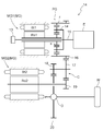
- FIG. 1 is a diagram illustrating a configuration of a hydraulic circuit of a hydraulic control device 1 according to the present embodiment.
- FIG. 2 is a skeleton diagram showing a mechanical configuration of the vehicle drive device 14 according to the embodiment of the present invention.
- the vehicle drive device 14 includes an internal combustion engine E and two rotary electric machines MG1 and MG2 as a driving force source, and outputs the output of the internal combustion engine E to the first rotary electric machine MG1 side. It is configured as a drive device for a so-called two-motor split type hybrid vehicle including a planetary gear device PG for power distribution that distributes to the wheels W and the second rotating electrical machine MG2 side.
- the first rotating electrical machine MG1 and the second rotating electrical machine MG2 are collectively referred to as a rotating electrical machine MG, and a planetary gear device PG for power distribution, a counter gear mechanism.
- C and the output differential gear device D are collectively referred to as a gear mechanism 2.
- the first oil passage 3, the second oil passage 4, the common oil passage 5, the third oil passage 6, and the discharge oil passage 7 are collectively referred to as oil passages 3 to 7.
- the vehicle drive device 14 includes an input shaft 15 that is drivingly connected to the internal combustion engine E, a first rotating electrical machine MG1, a second rotating electrical machine MG2, and a power distribution device.
- Planetary gear device PG Planetary gear device PG, a counter gear mechanism C, an output differential gear device D that distributes rotation and driving force transmitted through the counter gear mechanism C to a plurality of wheels W, and a rotor on the input shaft 15
- an oil pump 13 that is connected and driven by the internal combustion engine E.
- the planetary gear device PG distributes the rotation and driving force of the internal combustion engine E to the first rotating electrical machine MG1 and the counter gear mechanism C.
- the input shaft 15, the first rotating electrical machine MG1, and the planetary gear device PG that are drivingly connected to the internal combustion engine E are arranged coaxially.
- the second rotating electrical machine MG2, the counter gear mechanism C, and the output differential gear device D are arranged on different axes parallel to the input shaft 15, respectively.
- the internal combustion engine E various known internal combustion engines such as a spark ignition engine (gasoline engine) and a compression ignition engine (diesel engine) can be used.
- the input shaft 15 is drivingly connected to the internal combustion engine E via a flywheel, a damper, and a clutch (not shown).
- it is also preferable that the input shaft 15 is directly connected to the internal combustion engine E via one or two of the flywheel, the damper, and the clutch, or not through them.
- the first rotating electrical machine MG1 includes a first stator St1 fixed to the case, and a first rotor Ro1 that is rotatably supported on the radially inner side of the first stator St1.
- the first rotor Ro1 of the first rotating electrical machine MG1 is drive-coupled so as to rotate integrally with the sun gear s of the planetary gear device PG via the rotor shaft.
- the second rotating electrical machine MG2 includes a second stator St2 fixed to the case, and a second rotor Ro2 that is rotatably supported on the radially inner side of the second stator St2.
- the second rotor Ro2 of the second rotating electrical machine MG2 is connected to rotate integrally with the second rotating electrical machine output gear 19 via a rotor shaft.
- the second rotating electrical machine output gear 19 is engaged with the first counter gear 17 fixed to the counter gear mechanism C, and the rotation and driving force of the second rotating electrical machine MG2 are transmitted to the counter gear mechanism C. ing.
- the first rotating electrical machine MG ⁇ b> 1 and the second rotating electrical machine MG ⁇ b> 2 are AC motors, and are driven and controlled by a first inverter or a second inverter (not shown).
- the first rotating electrical machine MG1 is drivingly connected to the input shaft 15 and the counter gear mechanism C via the planetary gear device PG.
- the first rotating electrical machine MG1 generates power by the driving force input mainly through the sun gear s, charges a power storage device (not shown), or supplies power for driving the second rotating electrical machine MG2.
- the first rotating electrical machine MG1 may function as a motor that outputs a driving force by powering when the vehicle is traveling at a high speed or when the internal combustion engine E is started.
- the second rotating electrical machine MG2 is drivably coupled to the planetary gear device PG and the output differential gear device D via the counter gear mechanism C.
- the second rotating electrical machine MG2 mainly functions as a motor that assists the driving force for traveling the vehicle. However, when the vehicle is decelerated, the second rotating electrical machine MG2 functions as a generator and may function as a generator that regenerates the inertial force of the vehicle as electric energy. That is, the rotating electrical machine MG constitutes at least a part of the driving force source.
- the planetary gear device PG is configured by a single pinion type planetary gear mechanism arranged coaxially with the input shaft 15. That is, the planetary gear device PG includes a carrier ca that supports a plurality of pinion gears, and a sun gear s and a ring gear r that mesh with the pinion gears, as rotating elements.
- the input shaft 15 as the input member I, the differential input gear 20 as the output member O, and the first rotating electrical machine MG1 are drivingly connected to different rotating elements of the planetary gear device PG, respectively.
- the input shaft 15, the differential input gear 20, and the first rotating electrical machine MG ⁇ b> 1 do not pass through other rotating elements with respect to the three rotating elements of the sun gear s, the carrier ca, and the ring gear r of the planetary gear device PG.
- the driving elements are connected to the following rotating elements.
- the sun gear s is drivingly coupled so as to rotate integrally with the first rotor Ro1 of the first rotating electrical machine MG1.
- the carrier ca is drivingly connected so as to rotate integrally with the input shaft 15.
- the ring gear r is drivingly connected so as to rotate integrally with the counter drive gear 16.
- the counter drive gear 16 meshes with a first counter gear 17 fixed to the counter gear mechanism C, and the rotation of the ring gear r of the planetary gear device PG is transmitted to the counter gear mechanism C. .
- the first counter gear 17 is fixed to the counter shaft of the counter gear mechanism C on the internal combustion engine E side
- the second counter gear 18 is fixed on the first rotating electrical machine MG1 and the second rotating electrical machine MG2 side.
- the first counter gear 17 meshes with the counter drive gear 16 and the second rotating electrical machine output gear 19
- the second counter gear 18 meshes with the differential input gear 20 of the output differential gear device D.
- the counter gear mechanism C is drivingly connected to the planetary gear device PG (the ring gear r), the second rotating electrical machine MG2, and the output differential gear device D (the differential input gear 20).
- the output differential gear device D is generally used, and includes, for example, a differential gear mechanism using a plurality of bevel gears meshing with each other.
- the output differential gear unit D distributes the rotation and driving force transmitted to the differential input gear 20 to the wheels W that are the left and right driving wheels.
- the power distribution planetary gear unit PG, the counter gear mechanism C, and the output differential gear unit D to which the driving force from the driving force source is transmitted are the “gear mechanism” in the present invention. Equivalent to.
- the hydraulic control apparatus 1 includes an oil pump 13, oil passages 3 to 7 for guiding oil discharged from the oil pump 13 to the rotating electrical machine MG and the gear mechanism 2, a first relief valve R1, The second relief valve R ⁇ b> 2 and the throttle portion 8 are configured.
- the oil pump 13 side in each part in the oil passage is referred to as “upstream side”, and the side away from the oil pump 13 is referred to as “downstream side”. That is, the “upstream side” refers to the side where oil from the oil pump 13 flows in the oil passage, and the “downstream side” refers to the side where oil from the oil pump 13 flows out in the oil passage. .
- the oil pump 13 is an oil pump driven by a wheel driving force source, and supplies oil stored in the oil pan 9 to the rotating electrical machine MG and the gear mechanism 2 through the oil passages 3 to 7.
- the oil pump 13 is connected to the strainer 10 and a common oil passage 5 (described later).
- the rotor of the oil pump 13 is drivingly connected to the input shaft 15 as described above, and rotates at a speed proportional to the rotational speed of the output shaft of the internal combustion engine E.
- the oil pump 13 discharges an amount of oil corresponding to the rotational speed of the rotor. That is, as the rotational speed of the output shaft of the internal combustion engine E increases, the flow rate of oil discharged from the oil pump 13 increases and the discharge pressure of the oil also increases.
- the oil pump 13 Since the strainer 10 is connected to the upstream side of the oil pump 13, the oil pump 13 sucks the oil stored in the oil pan 9 through the strainer 10 and discharges it to the common oil passage 5.
- the oil pump 13 for example, an inscribed gear pump, an outer gear pump, a vane pump, or the like can be used.
- the oil pan 9 stores oil to be circulated in the vehicle drive device 14. Although details will be described later, part of the oil discharged from the first oil passage 3 flows into the oil pan 9 through the discharge oil passage 7 when the first relief valve R1 is opened.
- the strainer 10 is provided between the oil pan 9 and the oil pump 13, and is a filter for removing foreign substances contained in the oil when the oil pump 13 sucks the oil stored in the oil pan 9. It is.
- the oil passage in the hydraulic control device 1 includes a common oil passage 5 connected to the oil pump 13 and a first oil passage that is connected to the common oil passage 5 and guides oil flowing in from the common oil passage 5 to the gear mechanism 2. 3 and a second oil passage 4 that branches from the connecting portion 11 between the common oil passage 5 and the first oil passage 3 and guides oil flowing from the common oil passage 5 to the rotating electrical machine MG. Further, the oil passage further opens the third oil passage 6 branched from the first oil passage 3 and leading the oil flowing in from the first oil passage 3 to the rotating electrical machine MG, and the first relief valve R1. Accordingly, a discharge oil passage 7 for guiding the oil discharged from the first oil passage 3 to the oil pan 9 is provided.
- the oil passages 3 to 7 include the inside of the wall constituting the case member (not shown) in which the vehicle drive device 14 is stored, the inside of the shaft member provided in the vehicle drive device 14, the case It is formed inside an oil passage forming member provided inside or outside the member.
- the common oil passage 5 is provided between the oil pump 13 and the first oil passage 3 and the second oil passage 4, and guides oil discharged from the oil pump 13 to the first oil passage 3 and the second oil passage 4. It is an oil passage.
- one end of the common oil passage 5 is connected to a discharge port (not shown) of the oil pump 13, and the other end is connected to the first oil passage 3 and the second oil via the connection portion 11.
- the connecting portion 11 is a location where the common oil passage 5, the first oil passage 3, and the second oil passage 4 are connected.
- the first upstream oil passage 3 ⁇ / b> A that is a portion upstream of the throttle portion 8 in the first oil passage 3, and the portion upstream of the second relief valve R ⁇ b> 2 in the second oil passage 4.
- the second upstream oil passage 4A is a continuous integral oil passage. Therefore, in a static state, the oil pressure in the common oil passage 5, the oil pressure in the first upstream oil passage 3A, and the oil pressure in the second upstream oil passage 4A are the same pressure.
- the hydraulic pressure in the oil passage upstream of the throttle portion 8 is referred to as throttle upstream hydraulic pressure PA.
- the first oil passage 3 is an oil passage that connects the common oil passage 5 and the gear mechanism 2 and guides the oil flowing from the common oil passage 5 to the gear mechanism 2. Further, the first oil passage 3 is provided with a first relief valve R1 and a throttle portion 8 disposed on the upstream side of the first relief valve R1. In the present embodiment, a portion upstream of the throttle portion 8 in the first oil passage 3 is referred to as a first upstream oil passage 3A, and a portion downstream of the throttle portion 8 in the first oil passage 3 is referred to as a first downstream oil. This is called road 3B.
- the upstream edge part of the 1st oil path 3 (1st upstream oil path 3A) is connected to the common oil path 5 and the 2nd oil path 4 via the connection part 11, and the 1st oil path 3 (1st The downstream end of one downstream oil passage 3 ⁇ / b> B) is connected to the first supply port S ⁇ b> 1 for supplying oil to the gear mechanism 2.
- the first oil passage 3 (first downstream oil passage 3B) has a branching portion 12 that is a branch point to the third oil passage 6 on the downstream side of the first relief valve R1. That is, the first oil passage 3 is connected to the third oil passage 6 via the branch portion 12 in addition to the common oil passage 5 and the first supply port S1 to the gear mechanism 2. Furthermore, as will be described later, the first oil passage 3 (first downstream oil passage 3B) is also connected to the discharge oil passage 7 via the first relief valve R1.
- the throttle unit 8 is disposed in the flow path upstream of the first relief valve R1 in the first oil passage 3, and the flow rate of the oil passing through the throttle unit 8 is increased upstream of the throttle unit 8 (first By narrowing down from the upstream oil passage 3A), there is a difference between the hydraulic pressure of the first upstream oil passage 3A upstream of the throttle portion 8 and the hydraulic pressure of the first downstream oil passage 3B downstream of the throttle portion 8.
- the throttle portion 8 has a function of reducing the hydraulic pressure of the first downstream oil passage 3B to be lower than the hydraulic pressure of the first upstream oil passage 3A in a state where oil of a certain flow rate or more is flowing in the first oil passage 3.
- the throttle portion 8 has a cross-sectional area that is smaller than the cross-sectional area of the first upstream oil passage 3A.
- the throttle 8 is in the second oil passage 4 that is upstream of the throttle 8 in a state where the first relief valve R1 is discharging the oil in the first downstream oil passage 3B.
- the hydraulic pressure (throttle upstream hydraulic pressure PA) is configured to be larger than a first set hydraulic pressure P1 described later.
- the hydraulic pressure in the first downstream oil passage 3B which is the first oil passage 3 downstream of the throttle portion 8, is referred to as a throttle downstream hydraulic pressure PB.
- the first relief valve R ⁇ b> 1 is provided in the first downstream oil passage 3 ⁇ / b> B that is downstream from the throttle portion 8 of the first oil passage 3.
- the first relief valve R1 has an input port R1A connected to the first downstream oil passage 3B and an output port R1B connected to the discharge oil passage 7.
- the first relief valve R1 is connected to the input port R1A when the hydraulic pressure in the first downstream oil passage 3B downstream from the throttle portion 8, that is, the throttle downstream hydraulic pressure PB becomes equal to or higher than a predetermined valve opening pressure. Is communicated with the output port R1B, whereby the first downstream oil passage 3B and the discharge oil passage 7 are communicated with each other.
- the first relief valve R1 is configured such that when the throttle downstream hydraulic pressure PB in the first oil passage 3 on the downstream side of the throttle portion 8 becomes larger than the predetermined first set hydraulic pressure P1, the first oil passage 3 It is configured to discharge the oil inside. That is, the first set hydraulic pressure P1 is the valve opening pressure of the first relief valve R1.
- the first relief valve R1 is a balanced piston relief valve in which the input port R1A is connected between the throttle portion 8 and the branch portion 12 in the first oil passage 3, and is normally closed. ing.
- other types of valves may be used as long as the operating pressure can be set, such as a direct acting relief valve.
- the first set hydraulic pressure P1 is set to a hydraulic pressure within a predetermined range with the maximum required hydraulic pressure PBmax as a lower limit.
- the throttle downstream hydraulic pressure PB in the first oil passage 3 for supplying the gear mechanism 2 with the maximum amount of oil required for the lubrication of the gear mechanism 2 is the maximum required hydraulic pressure PBmax.
- the maximum flow rate necessary for the lubrication of the gear mechanism 2 is, for example, the gear mechanism in a state where the lubrication is most required within an assumed range, for example, when the torque transmitted by the gear mechanism 2 is maximized. 2 is the flow rate of the oil required to be supplied to 2.
- the first set hydraulic pressure P1 takes into account the error between the set pressure of the first relief valve R1 and the operating pressure, and is the maximum within a range that can ensure that the first relief valve R1 operates at the maximum required hydraulic pressure PBmax or more. It is preferable to set the pressure as close as possible to the required hydraulic pressure PBmax. As a result, the hydraulic pressure (throttle downstream hydraulic pressure PB) in the first downstream oil passage 3B can be brought as close as possible to the first set hydraulic pressure P1, and it is possible to suppress an excessive amount of oil from flowing into the gear mechanism 2. . In addition, since the first set oil pressure P1 is set to be equal to or greater than the maximum required oil pressure PBmax, it is possible to suppress a shortage of oil supplied to the gear mechanism 2.
- the drain oil passage 7 is an oil passage provided between the first relief valve R1 and the oil pan 9 for returning the oil surplus in the first oil passage 3 to the oil pan 9.
- the upstream end portion of the discharge oil passage 7 is connected to the output port R1B of the first relief valve R1, and the downstream end portion of the discharge oil passage 7 is connected to the oil pan 9.
- the second oil passage 4 is an oil passage connecting the common oil passage 5 and the rotating electrical machine MG.
- the upstream end portion of the second oil passage 4 is connected to the common oil passage 5 and the first oil passage 3 via the connection portion 11, and the downstream end portion of the second oil passage 4 is , Connected to a second supply port S2 for supplying oil to the rotating electrical machine MG.
- the second oil passage 4 is provided with a second relief valve R2.
- the portion upstream of the second relief valve R2 in the second oil passage 4 is called a second upstream oil passage 4A
- the portion downstream of the second relief valve R2 in the second oil passage 4 is the first. This is called the two downstream oil passages 4B.
- the second relief valve R2 is provided in the middle of the second oil passage 4, that is, between the common oil passage 5 in the second oil passage 4 and the rotating electrical machine MG.
- the second relief valve R2 has an input port R2A connected to the second upstream oil passage 4A and an output port R2B connected to the second downstream oil passage 4B.
- the second relief valve R2 is input when the hydraulic pressure in the second upstream oil passage 4A that is upstream from the second relief valve R2, that is, the throttle upstream hydraulic pressure PA becomes equal to or higher than a predetermined valve opening pressure.
- the second relief valve R2 is configured such that when the throttle upstream hydraulic pressure PA in the second oil passage 4 on the upstream side of the second relief valve R2 is greater than the predetermined second set hydraulic pressure P2, the second oil The upstream side and the downstream side of the second relief valve R2 in the path 4 are configured to communicate with each other. That is, the second set oil pressure P2 is the valve opening pressure of the second relief valve R2.
- the second relief valve R2 is a balance piston type relief valve, and is normally closed. As the second relief valve R2, other types of valves may be used as long as the operating pressure can be set, such as a direct acting relief valve.
- the second set oil pressure P2 is set to a higher oil pressure than the first set oil pressure P1.
- the throttle downstream hydraulic pressure PB in the first downstream oil passage 3B is controlled to the first set hydraulic pressure P1 so that an appropriate amount of oil can be supplied to the gear mechanism 2, and there is excess oil beyond that.
- the second relief valve R2 can be opened to supply oil to the rotating electrical machine MG.
- the oil supplied in this way is used for cooling and lubrication of the rotating electrical machine MG.
- the second set hydraulic pressure P2 is set to a lower hydraulic pressure than the upper limit hydraulic pressure PL that can withstand a portion having the lowest pressure resistance in the entire hydraulic circuit communicating with the common oil passage 5. . In this way, the hydraulic pressure of the entire hydraulic circuit can be prevented from exceeding the upper limit hydraulic pressure PL. That is, the second relief valve R2 can function as a safety valve for protecting the hydraulic circuit.
- the third oil path 6 is an oil path that connects the first oil path 3 and the rotating electrical machine MG and guides the oil flowing from the first oil path 3 to the rotating electrical machine MG.
- the upstream end portion of the third oil passage 6 is connected to the first oil passage 3 via the branch portion 12, and the downstream end portion of the third oil passage 6 is connected to the rotating electrical machine MG. Is connected to a third supply port S3.
- the third oil passage 6 is branched from the branch portion 12 downstream of the first relief valve R1 in the first oil passage 3, and guides the oil flowing in from the first oil passage 3 to the rotating electrical machine MG.
- the third oil passage 6 is configured such that more oil flows in than the oil that flows into the downstream portion of the branch portion 12 in the first downstream oil passage 3B.
- the cross-sectional area of the third oil passage 6 is configured to be larger than the cross-sectional area of the first oil passage 3.
- FIG. 3 is a diagram showing the relationship between the flow rate of oil flowing into each of the rotating electrical machine MG and the gear mechanism 2 and the number of revolutions of the oil pump.
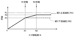
- FIG. 4 is a diagram showing the relationship between the throttle upstream hydraulic pressure PA and the throttle downstream hydraulic pressure PB, and the oil pump rotational speed.
- the number of revolutions of the oil pump is N.
- the throttle upstream oil pressure PA and the throttle downstream oil pressure PB are the first as shown in FIG. Since it is smaller than the set oil pressure P1, the first relief valve R1 is closed.
- the second relief valve R2 that opens at the second set oil pressure P2 that is set higher than the first set oil pressure P1 is also closed. At this time, the oil discharged from the oil pump 13 to the common oil passage 5 does not flow into the second downstream oil passage 4B but flows into the first upstream oil passage 3A.
- the oil that has flowed into the first upstream oil passage 3 ⁇ / b> A passes through the throttle portion 8 and flows into the first downstream oil passage 3 ⁇ / b> B downstream of the throttle portion 8.
- the oil that has flowed into the first downstream oil passage 3B flows to the branching portion 12 without being discharged from the first relief valve R1.
- Part of the oil that has reached the branching portion 12 flows into the gear mechanism 2 via a portion downstream of the branching portion 12 in the first downstream oil passage 3B, and the remaining part of the oil passes through the third oil passage 6.
- the flow rate of the oil flowing into the third oil passage 6 is the branched portion in the first downstream oil passage 3B. 12 is greater than the flow rate of the oil flowing into the portion downstream of 12. That is, the flow rate of the oil flowing into the rotating electrical machine MG is larger than the flow rate of the oil flowing into the gear mechanism 2.
- the flow rate of oil discharged from the oil pump 13 increases as the oil pump rotational speed N increases. Therefore, as shown in FIG. 3, the flow rate of the oil flowing into the gear mechanism 2 and the rotating electrical machine MG increases as the oil pump rotational speed N increases.
- the throttle upstream hydraulic pressure PA and the throttle downstream hydraulic pressure PB also increase.
- the throttle unit 8 does not function, and the throttle upstream hydraulic pressure PA and the throttle downstream hydraulic pressure PB are the same.
- the oil flowing into the first upstream oil passage 3A passes through the throttle portion 8 and flows into the first downstream oil passage 3B on the downstream side of the throttle portion 8.
- Part of the oil that has flowed into the first downstream oil passage 3B flows into the discharge oil passage 7 when the first relief valve R1 is opened, and the remaining portion reaches the branching portion 12 of the first downstream oil passage 3B.
- Part of the oil that has reached the branching portion 12 flows into the gear mechanism 2 via a portion downstream of the branching portion 12 in the first downstream oil passage 3B, and the remaining part of the oil passes through the third oil passage 6.
- N N1
- the flow rate of oil flowing into the gear mechanism 2 is the first reference flow rate Q1
- the flow rate of oil flowing into the rotating electrical machine MG is the first reference flow rate Q2.
- the oil pump rotational speed N is a value between N1 and N2, that is, when N1 ⁇ N ⁇ N2, the first relief valve R1 is opened, and the throttle downstream hydraulic pressure PB is It is controlled so as to be constant at a set oil pressure P1.
- the throttle upstream oil pressure PA is smaller than the second set oil pressure P2, so the second relief valve R2 is closed. Accordingly, the oil discharged from the oil pump 13 to the common oil passage 5 does not flow into the second downstream oil passage 4B but flows into the first upstream oil passage 3A.
- the oil that has flowed into the first upstream oil passage 3 ⁇ / b> A passes through the throttle portion 8 and flows into the first downstream oil passage 3 ⁇ / b> B on the downstream side of the throttle portion 8.
- Part of the oil that has flowed into the first downstream oil passage 3B flows into the discharge oil passage 7 when the first relief valve R1 is opened, and the remaining portion reaches the branching portion 12 of the first downstream oil passage 3B. Circulate.
- Part of the oil that has reached the branching portion 12 flows into the gear mechanism 2 via a portion downstream of the branching portion 12 in the first downstream oil passage 3B, and the remaining part of the oil passes through the third oil passage 6.
- the flow rate of the oil flowing into the third oil passage 6 becomes larger than the flow rate of the oil flowing into the downstream portion of the branch portion 12 in the first downstream oil passage 3B. That is, the flow rate of the oil flowing into the rotating electrical machine MG is larger than the flow rate of the oil flowing into the gear mechanism 2.
- the oil that has flowed into the discharge oil passage 7 is discharged to the oil pan 9.
- the throttle downstream hydraulic pressure PB tends to increase as the oil pump rotational speed N increases, but the first relief valve R1 is opened and the throttle of the first oil passage 3 is increased. Since the flow rate on the downstream side of the portion 8 is adjusted, the throttle downstream hydraulic pressure PB becomes constant at the first set hydraulic pressure P1. Specifically, when the throttle downstream hydraulic pressure PB is the first set hydraulic pressure P1, the flow rate of the oil flowing into the first downstream oil passage 3B is the first reference flow rate Q1 flowing into the gear mechanism 2 and the rotary electric machine MG. It is the sum (Q1 + Q2) with the inflowing second reference flow rate Q2.
- the oil that has flowed into the second downstream oil passage 4B flows into the rotating electrical machine MG.
- the flow rate of the oil flowing into the rotating electrical machine MG via the second downstream oil passage 4B is an additional supply flow rate ⁇ Q
- the flow rate of the oil flowing into the rotating electrical machine MG is 3rd when N> N2.
- N the sum (Q2 + ⁇ Q) of the second reference flow rate Q2 that flows in through the oil passage 6 and the additional supply flow rate ⁇ Q that flows in through the second oil passage 4.
- the flow rate of the first downstream oil passage 3B is controlled to be constant at Q1 + Q2, so that a large amount of oil from the oil pump 13 whose discharge amount increases as the oil pump rotational speed N increases.
- the additional supply flow rate ⁇ Q flowing into the rotating electrical machine MG via the second oil passage 4 increases as the oil pump rotational speed N increases.
- the first rotating electrical machine is in a state where the rotational speed of the internal combustion engine E (that is, the oil pump rotational speed N) is high and the output torque of the internal combustion engine E is large.
- the output torques of MG1 and second rotary electric machine MG2 often increase.
- the amount of heat generated by the first rotating electrical machine MG1 and the second rotating electrical machine MG2 increases, and it is necessary to supply and cool oil. Becomes higher.
- the oil pump 13 driven by the driving force source of the wheel W is generally used. As the number of rotations increases, the amount of heat generated by the rotating electrical machine MG tends to increase.
- oil of the additional supply flow rate ⁇ Q is also supplied to the rotating electrical machine MG in addition to the second reference flow rate Q2. can do. Therefore, oil can be appropriately supplied even in a situation where cooling or lubrication of the rotating electrical machine MG is particularly required.
- the rotor of the oil pump 13 is connected to the input shaft 15 of the internal combustion engine E and is driven by the internal combustion engine E.
- the configuration is not limited.
- the oil pump 13 may be configured so that the rotor of the oil pump 13 rotates in conjunction with a member that rotates at a speed proportional to the wheel W, such as a counter shaft or an output member.
- the embodiment of the present invention is not limited to this configuration.
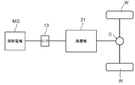
- the structure applied to an electric vehicle may be sufficient.
- the rotor of the oil pump 13 is drivingly connected to the rotor shaft of the rotating electrical machine MG that is a driving force source, and rotates at a speed proportional to the rotation of the rotor of the rotating electrical machine MG.
- the oil discharged from the oil pump 13 passes through the oil passages 3 to 6, the throttle portion 8, the first relief valve R1, and the second relief valve R2, as in the above-described embodiment, and the rotating electrical machine MG and the gears. It is supplied to the speed reducer 21 as the mechanism 2.
- the drain oil passage 7 is configured to be connected to the oil pan 9, but the embodiment of the present invention is not limited to this configuration.
- the structure connected to the oil path between the oil pump 13 and the strainer 10 may be sufficient. According to this configuration, since the oil of the first set hydraulic pressure P1 can be supplied to the downstream side of the oil pump 13, the drive loss of the oil pump 13 can be reduced.
- the cross-sectional area of the third oil passage 6 is larger than the cross-sectional area of the first oil passage 3.
- the embodiment of the present invention is not limited to this. That is, the cross-sectional area of the first oil passage 3 and the cross-sectional area of the third oil passage 6 may be the same size. Alternatively, the cross-sectional area of the third oil passage 6 may be smaller than the cross-sectional area of the first oil passage 3.
- the third oil passage 6 is provided, but the embodiment of the present invention is not limited to this. That is, a configuration without the third oil passage 6 may be used. In that case, oil is supplied to the rotating electrical machine MG only through the second relief valve R2 and the second oil passage 4.
- the present invention relates to an oil pump driven by a driving power source of a wheel, oil discharged from the oil pump, a rotating electrical machine constituting at least a part of the driving power source, and driving from the driving power source
- the present invention can be suitably used in a hydraulic control device including an oil passage that leads to a gear mechanism to which force is transmitted.
- Hydraulic control device 2 Gear mechanism 3: First oil passage 4: Second oil passage 5: Common oil passage 6: Third oil passage 8: Restriction portion 11: Connection portion 12: Branch portion 13: Oil pump E: Internal combustion engine (drive power source) D: Differential gear device for output (gear mechanism) C: Counter gear mechanism (gear mechanism) MG: rotating electrical machine R1: first relief valve R2: second relief valve P1: first set hydraulic pressure P2: second set hydraulic pressure PA: throttle upstream hydraulic pressure (hydraulic pressure in the second oil passage upstream of the second relief valve) ) PB: throttle downstream hydraulic pressure (hydraulic pressure in the first oil passage downstream from the throttle) PL: Upper limit oil pressure PBmax: Maximum required oil pressure
Landscapes
- Engineering & Computer Science (AREA)
- Mechanical Engineering (AREA)
- General Engineering & Computer Science (AREA)
- Chemical & Material Sciences (AREA)
- Combustion & Propulsion (AREA)
- Transportation (AREA)
- Physics & Mathematics (AREA)
- Fluid Mechanics (AREA)
- Hybrid Electric Vehicles (AREA)
- General Details Of Gearings (AREA)
Description
ここで、オイルポンプは車輪の駆動力源により駆動されるため、オイルポンプの吐出圧が高い状態では、駆動力源の少なくとも一部を構成する回転電機の負荷も高くなっている可能性が高い。上記特徴構成によれば、このように回転電機の負荷が高く、回転電機の冷却や潤滑が特に必要とされる状況において、オイルポンプの吐出圧が高くなって回転電機に油が供給されることになる。従って、回転電機に油を供給する必要性が特に高い状況で適切に油を供給することができる。以上のとおり、この特徴構成によれば、簡易な構成によって、ギヤ機構及び回転電機の双方に適切な量の油を供給することができる。
図2に示すように、車両用駆動装置14は、内燃機関Eに駆動連結された入力軸15と、第一回転電機MG1と、第二回転電機MG2と、動力分配用の遊星歯車装置PGと、カウンタギヤ機構Cと、カウンタギヤ機構Cを介して伝達される回転及び駆動力を複数の車輪Wに分配する出力用差動歯車装置Dと、ロータが入力軸15に連結されて、内燃機関Eによって駆動されるオイルポンプ13と、を備えている。遊星歯車装置PGは、内燃機関Eの回転及び駆動力を第一回転電機MG1とカウンタギヤ機構Cとに分配する。
次に、オイルポンプ13から吐出され、車両用駆動装置14内を循環する油の油圧を制御する油圧制御装置1の構成について、図1に示した油圧回路図を用いて説明する。
図1に示すように、油圧制御装置1は、オイルポンプ13と、オイルポンプ13から吐出された油を回転電機MG及びギヤ機構2へ導く油路3~7と、第一リリーフ弁R1と、第二リリーフ弁R2と、絞り部8とから構成される。なお、以下の説明では、油路中の各部におけるオイルポンプ13側を「上流側」、オイルポンプ13から離れる側を「下流側」とする。すなわち、「上流側」とは、油路中においてオイルポンプ13からの油が流入される側を指し、「下流側」とは、油路中においてオイルポンプ13からの油が流出する側を指す。
本実施形態に係る油圧制御の内容について、図3及び図4を用いて説明する。図3は、回転電機MG及びギヤ機構2のそれぞれへ流入する油の流量と、オイルポンプ回転数との関係を示した図である。図4は、絞り上流油圧PA及び絞り下流油圧PBのそれぞれと、オイルポンプ回転数との関係を示した図である。ここでは、オイルポンプ回転数をNとする。
(1)上記の実施形態では、オイルポンプ13のロータが内燃機関Eの入力軸15に連結されて、内燃機関Eによって駆動される構成であるが、本発明の実施形態はこの構成に限定されるものではない。オイルポンプ13は、オイルポンプ13のロータが、例えばカウンタ軸や出力部材等のように車輪Wと比例する速度で回転する部材に連動して回転するように設けられる構成であってもよい。
2:ギヤ機構
3:第一油路
4:第二油路
5:共通油路
6:第三油路
8:絞り部
11:接続部
12:分岐部
13:オイルポンプ
E:内燃機関(駆動力源)
D:出力用差動歯車装置(ギヤ機構)
C:カウンタギヤ機構(ギヤ機構)
MG:回転電機
R1:第一リリーフ弁
R2:第二リリーフ弁
P1:第一設定油圧
P2:第二設定油圧
PA:絞り上流油圧(第二リリーフ弁よりも上流側の第二油路内の油圧)
PB:絞り下流油圧(絞り部よりも下流側の第一油路内の油圧)
PL:上限油圧
PBmax:最大必要油圧
Claims (5)
- 車輪の駆動力源により駆動されるオイルポンプと、
前記オイルポンプから吐出された油を、前記駆動力源の少なくとも一部を構成する回転電機、及び、前記駆動力源からの駆動力が伝達されるギヤ機構へ導く油路と、を備えた油圧制御装置であって、
前記油路は、前記オイルポンプに接続された共通油路と、当該共通油路に接続されて前記共通油路から流入する油を前記ギヤ機構へ導く第一油路と、前記共通油路と前記第一油路との接続部から分岐して前記共通油路から流入する油を前記回転電機へ導く第二油路とを備え、
前記第一油路に、第一リリーフ弁と、当該第一リリーフ弁よりも上流側に配設される絞り部とが設けられ、
前記第二油路に、第二リリーフ弁が設けられ、
前記第一リリーフ弁は、前記絞り部よりも下流側の前記第一油路内の油圧が予め定めた第一設定油圧より大きくなった場合に、前記第一油路内の油を排出するように構成され、
前記第二リリーフ弁は、当該第二リリーフ弁よりも上流側の前記第二油路内の油圧が予め定めた第二設定油圧より大きくなった場合に、前記第二油路の前記第二リリーフ弁よりも上流側と下流側とを連通するように構成され、
前記第二設定油圧が、前記第一設定油圧よりも高く設定されている車両用油圧制御装置。 - 前記第一油路における前記第一リリーフ弁よりも下流の分岐部から分岐され、前記第一油路から流入する油を前記回転電機へ導く第三油路をさらに備える請求項1記載の車両用油圧制御装置。
- 前記第二リリーフ弁は、前記共通油路に連通している油圧回路の全体の中で最も耐圧性の低い箇所が耐えられる上限油圧よりも低い油圧で、前記第二油路の前記第二リリーフ弁よりも上流側と下流側とを連通する請求項1又は2に記載の車両用油圧制御装置。
- 前記絞り部は、前記第一リリーフ弁が前記第一油路内の油を排出している状態で、前記第二リリーフ弁よりも上流側の前記第二油路内の油圧が前記第一設定油圧より大きくなるように構成されている請求項1から3のいずれか一項に記載の車両用油圧制御装置。
- 前記ギヤ機構の潤滑に最大限必要な流量の油を前記ギヤ機構に供給する前記第一油路内の油圧が最大必要油圧であり、
前記第一設定油圧は、前記最大必要油圧を下限とする予め定められた範囲内の油圧に設定されている請求項1から4のいずれか一項に記載の車両用油圧制御装置。
Priority Applications (3)
| Application Number | Priority Date | Filing Date | Title |
|---|---|---|---|
| US14/414,566 US9803658B2 (en) | 2012-08-23 | 2013-08-02 | Vehicle hydraulic control device |
| CN201380039000.6A CN104487305B (zh) | 2012-08-23 | 2013-08-02 | 车辆用液压控制装置 |
| DE112013003307.0T DE112013003307B4 (de) | 2012-08-23 | 2013-08-02 | Fahrzeughydrauliksteuervorrichtung |
Applications Claiming Priority (2)
| Application Number | Priority Date | Filing Date | Title |
|---|---|---|---|
| JP2012184385A JP5899594B2 (ja) | 2012-08-23 | 2012-08-23 | 車両用油圧制御装置 |
| JP2012-184385 | 2012-08-23 |
Publications (1)
| Publication Number | Publication Date |
|---|---|
| WO2014030528A1 true WO2014030528A1 (ja) | 2014-02-27 |
Family
ID=50149838
Family Applications (1)
| Application Number | Title | Priority Date | Filing Date |
|---|---|---|---|
| PCT/JP2013/071037 Ceased WO2014030528A1 (ja) | 2012-08-23 | 2013-08-02 | 車両用油圧制御装置 |
Country Status (5)
| Country | Link |
|---|---|
| US (1) | US9803658B2 (ja) |
| JP (1) | JP5899594B2 (ja) |
| CN (1) | CN104487305B (ja) |
| DE (1) | DE112013003307B4 (ja) |
| WO (1) | WO2014030528A1 (ja) |
Cited By (7)
| Publication number | Priority date | Publication date | Assignee | Title |
|---|---|---|---|---|
| CN104228541A (zh) * | 2014-09-28 | 2014-12-24 | 上海羽翼船舶设备有限公司 | 一种重型车辆液压混合动力装置 |
| GB2529027A (en) * | 2014-06-16 | 2016-02-10 | Cummins Inc | Lubrication system and method for transmission and engine gear devices |
| GB2536284A (en) * | 2015-03-13 | 2016-09-14 | Bae Systems Plc | Hydraulic system |
| WO2017163855A1 (ja) * | 2016-03-25 | 2017-09-28 | アイシン・エィ・ダブリュ株式会社 | 油圧制御装置 |
| US20220268354A1 (en) * | 2021-02-11 | 2022-08-25 | Zf Friedrichshafen Ag | Vehicle transmission with a lubrication system and a connection for attaching a power take-off module to the vehicle transmission |
| CN118582427A (zh) * | 2024-01-22 | 2024-09-03 | 浙江宏祝机械有限公司 | 一种液压动力站及其控制方法 |
| US12169017B2 (en) | 2022-09-16 | 2024-12-17 | Zf Friedrichshafen Ag | Vehicle transmission with a power take-off, vehicle and working machine arrangement |
Families Citing this family (16)
| Publication number | Priority date | Publication date | Assignee | Title |
|---|---|---|---|---|
| JP6182778B2 (ja) * | 2014-10-31 | 2017-08-23 | トヨタ自動車株式会社 | ハイブリッド車両 |
| JP6660791B2 (ja) * | 2016-03-30 | 2020-03-11 | 株式会社Subaru | ハイブリッド駆動装置 |
| JP6799492B2 (ja) * | 2017-04-07 | 2020-12-16 | 株式会社Subaru | 電動モータの冷却装置 |
| JP6846301B2 (ja) * | 2017-06-27 | 2021-03-24 | 川崎重工業株式会社 | ヘリコプタ用の動力伝達装置 |
| CN108194440B (zh) * | 2017-11-14 | 2020-03-31 | 武汉船用机械有限责任公司 | 一种液压调速阀及液压系统 |
| DE102018211360B4 (de) * | 2018-07-10 | 2020-10-29 | Audi Ag | Schmiermittelversorgungssystem für eine Antriebsvorrichtung eines elektrisch betriebenen Fahrzeugs |
| DE102019123981B4 (de) * | 2019-09-06 | 2022-03-24 | Dr. Ing. H.C. F. Porsche Aktiengesellschaft | Elektrofahrzeug mit einem 1-Gang-Getriebe |
| DE102019123982B4 (de) * | 2019-09-06 | 2025-04-17 | Dr. Ing. H.C. F. Porsche Aktiengesellschaft | Elektrofahrzeug mit einem 2-Gang-Getriebe |
| JP7091304B2 (ja) * | 2019-12-11 | 2022-06-27 | ダイハツ工業株式会社 | 冷却構造 |
| DE102020210978A1 (de) * | 2020-08-31 | 2022-03-03 | Volkswagen Aktiengesellschaft | Kühlverfahren für ein hydraulisches Element eines Kühlölkreislaufs, Steuergerät, Kraftfahrzeug |
| US11585428B2 (en) * | 2020-09-08 | 2023-02-21 | Deere & Company | Cold start lubricant distribution systems and work vehicles including the same |
| CN113124141B (zh) * | 2021-04-29 | 2022-07-12 | 东风商用车有限公司 | 变速箱润滑方法 |
| DE102021123189A1 (de) | 2021-09-08 | 2023-03-09 | Schaeffler Technologies AG & Co. KG | Elektrischer Antrieb für ein Fahrzeug mit einem Durchgangsventil, Durchgangsventil, insbesondere für die elektrische Antriebseinheit sowie Druckregeleinheit mit dem Durchgangsventil |
| DE102022100573B3 (de) * | 2022-01-12 | 2023-05-17 | Schaeffler Technologies AG & Co. KG | Hydrauliksystem mit Hoch- und Trockensumpf |
| DE102023200684A1 (de) * | 2023-01-27 | 2024-08-01 | Zf Friedrichshafen Ag | Versorgungssystem |
| DE102024208774A1 (de) * | 2024-09-16 | 2026-03-19 | Zf Friedrichshafen Ag | Versorgungssystem für eine eine elektrische Maschine aufweisende Vorrichtung sowie elektrisch antreibbare Fahrzeugachse |
Citations (5)
| Publication number | Priority date | Publication date | Assignee | Title |
|---|---|---|---|---|
| JPH0953603A (ja) * | 1995-08-10 | 1997-02-25 | Aqueous Res:Kk | 駆動装置 |
| JPH10141036A (ja) * | 1996-09-13 | 1998-05-26 | Nippon Soken Inc | 内燃機関の潤滑油圧回路 |
| JP2002276322A (ja) * | 2001-03-22 | 2002-09-25 | Aisin Seiki Co Ltd | エンジン油供給装置 |
| JP2006067640A (ja) * | 2004-08-24 | 2006-03-09 | Honda Motor Co Ltd | 電動ポンプ制御装置 |
| JP2008190636A (ja) * | 2007-02-05 | 2008-08-21 | Mitsubishi Heavy Ind Ltd | トランスミッションのオイルシステム |
Family Cites Families (12)
| Publication number | Priority date | Publication date | Assignee | Title |
|---|---|---|---|---|
| US5718302A (en) * | 1994-09-27 | 1998-02-17 | Aisin Aw Co., Ltd. | Hydraulic circuit for electric car drive train |
| JP3691469B2 (ja) * | 2002-08-07 | 2005-09-07 | 本田技研工業株式会社 | ハイブリッド車両の油圧回路 |
| JP4630651B2 (ja) * | 2004-12-02 | 2011-02-09 | 本田技研工業株式会社 | 油圧供給装置 |
| JP4800014B2 (ja) * | 2005-03-31 | 2011-10-26 | 本田技研工業株式会社 | 油圧回路の制御装置 |
| JP4464984B2 (ja) * | 2007-04-20 | 2010-05-19 | トヨタ自動車株式会社 | 車両用オイル供給装置 |
| CN101994825B (zh) * | 2009-08-24 | 2014-04-30 | 上海华普国润汽车有限公司 | 用于混合动力变速器的液压控制装置 |
| JP5546311B2 (ja) * | 2010-03-29 | 2014-07-09 | アイシン・エィ・ダブリュ株式会社 | 車両用駆動装置 |
| JP2011235806A (ja) | 2010-05-12 | 2011-11-24 | Toyota Motor Corp | 車両の駆動装置 |
| CN102328577B (zh) * | 2010-07-12 | 2014-06-25 | 上海捷能汽车技术有限公司 | 液压系统及包括其的混合动力车辆 |
| JP6114128B2 (ja) * | 2013-07-05 | 2017-04-12 | 本田技研工業株式会社 | 自動変速装置 |
| DE102013221658B4 (de) * | 2013-10-24 | 2025-05-15 | Zf Friedrichshafen Ag | Hydrauliksystem einer Getriebevorrichtung mit einem Schmierkreislauf |
| JP6128082B2 (ja) * | 2014-09-08 | 2017-05-17 | トヨタ自動車株式会社 | 車両の油圧制御装置 |
-
2012
- 2012-08-23 JP JP2012184385A patent/JP5899594B2/ja not_active Expired - Fee Related
-
2013
- 2013-08-02 US US14/414,566 patent/US9803658B2/en not_active Expired - Fee Related
- 2013-08-02 WO PCT/JP2013/071037 patent/WO2014030528A1/ja not_active Ceased
- 2013-08-02 CN CN201380039000.6A patent/CN104487305B/zh not_active Expired - Fee Related
- 2013-08-02 DE DE112013003307.0T patent/DE112013003307B4/de not_active Expired - Fee Related
Patent Citations (5)
| Publication number | Priority date | Publication date | Assignee | Title |
|---|---|---|---|---|
| JPH0953603A (ja) * | 1995-08-10 | 1997-02-25 | Aqueous Res:Kk | 駆動装置 |
| JPH10141036A (ja) * | 1996-09-13 | 1998-05-26 | Nippon Soken Inc | 内燃機関の潤滑油圧回路 |
| JP2002276322A (ja) * | 2001-03-22 | 2002-09-25 | Aisin Seiki Co Ltd | エンジン油供給装置 |
| JP2006067640A (ja) * | 2004-08-24 | 2006-03-09 | Honda Motor Co Ltd | 電動ポンプ制御装置 |
| JP2008190636A (ja) * | 2007-02-05 | 2008-08-21 | Mitsubishi Heavy Ind Ltd | トランスミッションのオイルシステム |
Cited By (10)
| Publication number | Priority date | Publication date | Assignee | Title |
|---|---|---|---|---|
| GB2529027A (en) * | 2014-06-16 | 2016-02-10 | Cummins Inc | Lubrication system and method for transmission and engine gear devices |
| GB2529027B (en) * | 2014-06-16 | 2020-07-01 | Cummins Inc | Lubrication system and method for transmission and engine gear devices |
| CN104228541A (zh) * | 2014-09-28 | 2014-12-24 | 上海羽翼船舶设备有限公司 | 一种重型车辆液压混合动力装置 |
| GB2536284A (en) * | 2015-03-13 | 2016-09-14 | Bae Systems Plc | Hydraulic system |
| WO2017163855A1 (ja) * | 2016-03-25 | 2017-09-28 | アイシン・エィ・ダブリュ株式会社 | 油圧制御装置 |
| US10557547B2 (en) | 2016-03-25 | 2020-02-11 | Aisin Aw Co., Ltd. | Hydraulic control device |
| US20220268354A1 (en) * | 2021-02-11 | 2022-08-25 | Zf Friedrichshafen Ag | Vehicle transmission with a lubrication system and a connection for attaching a power take-off module to the vehicle transmission |
| US12129921B2 (en) * | 2021-02-11 | 2024-10-29 | Zf Friedrichshafen Ag | Vehicle transmission with a lubrication system and a connection for attaching a power take-off module to the vehicle transmission |
| US12169017B2 (en) | 2022-09-16 | 2024-12-17 | Zf Friedrichshafen Ag | Vehicle transmission with a power take-off, vehicle and working machine arrangement |
| CN118582427A (zh) * | 2024-01-22 | 2024-09-03 | 浙江宏祝机械有限公司 | 一种液压动力站及其控制方法 |
Also Published As
| Publication number | Publication date |
|---|---|
| CN104487305B (zh) | 2017-02-08 |
| CN104487305A (zh) | 2015-04-01 |
| US20150192150A1 (en) | 2015-07-09 |
| DE112013003307T5 (de) | 2015-03-19 |
| JP5899594B2 (ja) | 2016-04-06 |
| DE112013003307B4 (de) | 2022-03-31 |
| US9803658B2 (en) | 2017-10-31 |
| JP2014040219A (ja) | 2014-03-06 |
Similar Documents
| Publication | Publication Date | Title |
|---|---|---|
| JP5899594B2 (ja) | 車両用油圧制御装置 | |
| US11192444B2 (en) | Drive unit for a hybrid vehicle | |
| US10253868B2 (en) | Lubricating apparatus of vehicle | |
| JP6128082B2 (ja) | 車両の油圧制御装置 | |
| EP2930079B1 (en) | Oil supply device | |
| JP4940714B2 (ja) | 駆動装置の制御装置 | |
| KR20180018412A (ko) | 하이브리드 차량 | |
| US9863294B2 (en) | Hydraulic control system for vehicle | |
| CN109555845B (zh) | 车辆用动力传递装置的冷却装置 | |
| US9777828B2 (en) | Fluid supply device | |
| JP2002213594A (ja) | 車両用自動変速機の油圧制御装置 | |
| US20110297258A1 (en) | Hydraulic control circuit of vehicular power transmission apparatus | |
| JP2010261534A (ja) | 車両用駆動装置 | |
| CN116105052A (zh) | 车辆的润滑结构 | |
| JP2011259590A (ja) | 車両用駆動装置 | |
| JP2019162927A (ja) | 潤滑装置 | |
| KR20190008288A (ko) | 트랜스액슬 장치 | |
| JP2014040111A (ja) | ハイブリッド車両 | |
| JP2023031159A (ja) | 車両用潤滑システムおよびその制御装置 | |
| CN104769315B (zh) | 挖土机 | |
| JP2019119402A (ja) | 潤滑装置 | |
| JP2011235806A (ja) | 車両の駆動装置 | |
| JP5527240B2 (ja) | 動力伝達システムの潤滑装置 | |
| US20220213957A1 (en) | Vehicle drive device | |
| JP6413993B2 (ja) | 電動機の冷却装置 |
Legal Events
| Date | Code | Title | Description |
|---|---|---|---|
| 121 | Ep: the epo has been informed by wipo that ep was designated in this application |
Ref document number: 13830425 Country of ref document: EP Kind code of ref document: A1 |
|
| WWE | Wipo information: entry into national phase |
Ref document number: 14414566 Country of ref document: US |
|
| WWE | Wipo information: entry into national phase |
Ref document number: 112013003307 Country of ref document: DE Ref document number: 1120130033070 Country of ref document: DE |
|
| 122 | Ep: pct application non-entry in european phase |
Ref document number: 13830425 Country of ref document: EP Kind code of ref document: A1 |