WO2014017113A1 - 電動工具におけるフックの取付構造 - Google Patents
電動工具におけるフックの取付構造 Download PDFInfo
- Publication number
- WO2014017113A1 WO2014017113A1 PCT/JP2013/055381 JP2013055381W WO2014017113A1 WO 2014017113 A1 WO2014017113 A1 WO 2014017113A1 JP 2013055381 W JP2013055381 W JP 2013055381W WO 2014017113 A1 WO2014017113 A1 WO 2014017113A1
- Authority
- WO
- WIPO (PCT)
- Prior art keywords
- hook
- housing
- sphere
- guide groove
- locking
- Prior art date
- Legal status (The legal status is an assumption and is not a legal conclusion. Google has not performed a legal analysis and makes no representation as to the accuracy of the status listed.)
- Ceased
Links
Images





Classifications
-
- B—PERFORMING OPERATIONS; TRANSPORTING
- B25—HAND TOOLS; PORTABLE POWER-DRIVEN TOOLS; MANIPULATORS
- B25F—COMBINATION OR MULTI-PURPOSE TOOLS NOT OTHERWISE PROVIDED FOR; DETAILS OR COMPONENTS OF PORTABLE POWER-DRIVEN TOOLS NOT PARTICULARLY RELATED TO THE OPERATIONS PERFORMED AND NOT OTHERWISE PROVIDED FOR
- B25F5/00—Details or components of portable power-driven tools not particularly related to the operations performed and not otherwise provided for
- B25F5/02—Construction of casings, bodies or handles
Definitions
- the present invention relates to a hook mounting structure in a power tool in which a hanging hook is attached to a housing of the power tool.
- a hook housing portion formed on the housing of the electric tool and opened left and right has a substantially U-shape.
- the hook is slidably accommodated in the left-right direction, and the hook accommodating portion has a left protruding position where the locking end portion of the hook protrudes from the left side of the hook accommodating portion, and the locking end portion of the hook accommodating portion.
- holding means capable of holding the right projecting position projecting from the right side and the housing position where the locking end portion fits in the hook housing portion are provided.
- Patent Document 1 in order to hold the locking end of the hook in the upper protruding position that protrudes upward from the hook receiving portion, the hook receiving portion is moved to the upper protruding position of the locking end. It is disclosed that an escape portion that allows rotation of the coil spring and a coil spring that holds the locking end portion in the upper protruding position are provided.
- the present invention has been proposed in view of such a situation, and an object thereof is to provide a hook mounting structure in an electric tool that simplifies an operation for arranging hooks at a plurality of different positions.
- the invention of claim 1 is a hook mounting structure in a power tool for mounting a hanging hook to a housing of a power tool, A plurality of spheres rotatable in different directions are arranged in the housing, and the hooks are connected to the spheres.
- the invention of claim 2 is characterized in that, in claim 1, one of the plurality of different directions is a direction in which an engaging end portion of the hook can be inserted and locked into the housing.
- the invention of claim 3 is characterized in that, in claim 2, when the locking end portion is inserted and locked to the housing, a locking opening is formed between the hook and the housing. To do.
- the engaging portion is formed in one of the housing and the sphere, and the engaging portion is engaged with the other along the plurality of different directions.
- the hooks can be arbitrarily connected in the different directions. It is characterized in that it can be fixed in position.
- the invention of claim 5 is characterized in that, in claim 1, the power tool is a reciprocating saw.
- the housing extends in the front-rear direction to accommodate the motor, protrudes forward from the front end of the housing, and reciprocates by driving the motor.
- the spheres connected to each other are arranged.
- the hook connected to the sphere can be rotated in a plurality of different directions only by the rotation of the sphere. Therefore, the operation for arranging the hooks at a plurality of different positions can be easily performed.
- the sphere when the hook is not used, the sphere is rotated in a direction in which the hook end of the hook can be inserted and locked into the housing, so that the hook end is accommodated in the housing. it can.
- the electric tool when the locking end is inserted and locked in the housing, the electric tool can be suspended from the locking member or the like by locking the locking opening to the locking member or the like. It becomes possible.
- the hook can be fixed at the position.
- the hook can be easily arranged on the left side or the right side in the left-right direction by rotating the sphere in the left-right direction perpendicular to the front-rear direction of the housing.
- FIG. 3 is a cross-sectional view taken along line AA in FIG. 2. It is a perspective view of the spherical body arrange
- FIG. 7 is a sectional view taken along the line BB in FIG. 6.
- FIG. 10 is a cross-sectional view taken along line CC of FIG. 9. It is a perspective view of the rechargeable reciprocating saw with the hook fixed to the right position. It is a sectional side view of the rechargeable reciprocating saw with the hook fixed to the right position.
- FIG. 13 is a cross-sectional view taken along line DD of FIG. 12.
- the rechargeable reciprocating saw 1 includes a housing 2.
- the housing 2 extends in the front-rear direction X (the left-right direction in FIGS. 1 and 2) of the rechargeable reciprocating saw 1, and a handle 3 is formed at the rear end of the housing 2.
- the rechargeable reciprocating saw 1 is an example of the electric tool of the present invention.
- a motor M is accommodated near the center in the front-rear direction X in the housing 2.
- a slider (not shown) having a tool holder 5 at the tip is projected forward from the front end of the housing 2 (the right side in FIGS. 1 and 2).
- a linear cutting blade 6 (see FIG. 2) can be attached to the tool holder 5 in the same axial direction as the slider.
- a reciprocating mechanism (not shown) that converts the rotation of the motor M into a linear reciprocating motion in the axial direction of the slider (left and right direction in FIGS. 1 and 2) is housed in the front portion of the housing 2.
- a guide shoe 8 is supported on the front end surface of the housing 2 so as to be orthogonal to the housing 2.
- the guide shoe 8 is provided with a through hole 9 (see FIG. 1) penetrating in the front-rear direction (left and right direction in FIG. 2), so that the cutting blade 6 can penetrate the guide shoe 8 through the through hole 9. ing.
- the handle 3 is substantially U-shaped in a side view as shown in FIG.
- the handle 3 houses a switch 12 having a trigger 11.
- the trigger 11 is exposed to the outside of the handle 3 from the opening of the handle 3 and can be pushed into the handle 3.
- a battery pack mounting portion 13 is formed at the lower end of the handle 3.
- a battery pack 14 is detachably mounted on the battery pack mounting portion 13.
- a hook 20 used to suspend the rechargeable reciprocating saw 1 on, for example, a locking member provided on a wall is attached to the upper surface of the handle 3.
- the hook 20 is formed by bending a metal (for example, aluminum) rod-like body into a substantially U shape, and a base end portion 21 and a locking portion positioned to face the base end portion 21. 22, and a folded portion 23 that is folded back from the distal end side of the proximal end portion 21 toward the locking portion 22 between the proximal end portion 21 and the locking portion 22.
- the base end portion 21 is connected to a sphere 24 (see FIG. 2) as will be described later.
- an accommodation space 25 is formed in the upper portion of the handle 3 so as to open the upper surface of the handle 3 and accommodate a metal (for example, iron) sphere 24.
- the housing space 25 is elongated in the front-rear direction X.
- a hemispherical concave groove 26 (see FIGS. 2 and 3) is provided at the middle position P (see FIG. 3) in the left-right direction Y of the housing 2 orthogonal to the front-rear direction X on the bottom surface of the housing space 25. ing.
- the sphere 24 is placed in the middle position P by being inserted into the concave groove 26.
- the spherical body 24 is rotatable along the concave groove 26.
- the sphere 24 is formed in a semicircular shape extending along the left and right sides of the sphere 24 along the semicircular surface of the sphere 24, and is recessed in the semicircular surface
- the first guide groove 31 is connected to the central portion of the first guide groove 31 and extends substantially perpendicular to the first guide groove 31 from the central portion in the forward direction of the sphere 24 along the half peripheral surface.
- a second guide groove 32 As shown in FIG. 4, a first engaging recess 33 that opens to the first guide groove 31 is formed at the center of the first guide groove 31.
- the first guide groove 31 has a second engaging recess 34 that opens in the first guide groove 31 at one end, and a second opening that opens in the first guide groove 31 at the other end of the first guide groove 31.
- Three engaging recesses 35 are respectively formed.
- a fourth engagement recess 36 that opens to the second guide groove 32 is formed at the front end of the second guide groove 32.
- the sphere 24 has a long hole 37 that opens to the peripheral surface and extends from the peripheral surface toward the center of the sphere 24.
- the base end 21 of the hook 20 can be inserted into the long hole 37.
- the sphere 24 has a pin introduction hole 38 (see FIG. 2) that opens in the circumferential surface, extends in a direction orthogonal to the long hole 37, and communicates with the long hole 37. is doing.
- the base end portion 21 is formed with a through hole 39 (see FIGS. 3 and 7) that passes through the base end portion 21 in a direction orthogonal to the axial direction of the base end portion 21.
- the pin introduction hole 38 and the through hole 39 communicate with each other.
- the positioning pin 40 (see FIGS. 3 and 7) is introduced into the pin introduction hole 38 in this state, the distal end side of the positioning pin 40 can be fitted into the through hole 39. In this way, the base end portion 21 of the hook 20 is prevented from coming off in the long hole 37, and the hook 20 is connected to the sphere 24.
- a coil spring accommodation hole 45 is formed in the bottom surface of the accommodation space 25 and opens at the bottom center of the concave groove 26.
- the coil spring 46 accommodated in the coil spring accommodation hole 45 urges a substantially cylindrical lock pin 47 toward the spherical body 24.
- 2 and 3 show a state in which the lock pin 47 is engaged with the fourth engagement recess 36 of the sphere 24 by the urging force of the coil spring 46.
- the lock pin 47 is freely engageable with the first engagement recess 33 to the third engagement recess 35 (see FIG. 4) in addition to the fourth engagement recess 36.
- the coil spring 46 and the lock pin 47 are examples of the engagement portion of the present invention, and the first engagement recess 33 to the fourth engagement recess 36 are examples of the engaged portion of the present invention.
- a slit 50 is formed in the upper portion of the handle 3 and opens in the upper surface of the handle 3 and extends in the left-right direction Y of the housing 2 continuously with the rear end portion of the housing space 25. .
- the slits 50 are also formed on the right and left side surfaces of the handle 3 so as to be orthogonal to the accommodation space 25.
- the slit 50 is used to allow the proximal end portion 21 of the hook 20 to escape from the accommodation space 25 in order to allow the hook 20 to rotate as will be described later.
- a locking hole 51 that opens on the upper surface of the housing 3 is formed at a position in front of the handle 3 in the front-rear direction X.
- the locking hole 51 can be locked by inserting an end portion 29 (hereinafter referred to as “locking end portion 29”) of the locking portion 22 of the hook 20 from above the housing 2 as described below. It is.
- the base end 21 protrudes upward from the accommodation space 25 in a standing state
- the folded portion 23 is disposed in the front-rear direction X above the housing 2
- the locking end 29 is A state of being inserted into and locked into the locking hole 51 from above the housing 2 and accommodated in the locking hole 51 can be created.
- a locking opening 53 is formed between the hook 20 and the housing 2.
- the locking opening 53 is a space surrounded by the upper surface of the housing 2 and the hook 20.
- the locking end portion 29 can be prevented from coming off in the locking hole 51, so that, for example, when the locking opening 53 is locked to a locking member provided on the wall, the rechargeable reciprocating saw 1 is It becomes possible to suspend it on the locking member via 53.
- the hook 20 when the hook 20 is arranged at an upper position (see FIGS. 5 and 7) where the locking portion 22 is located above the housing 2, the following operation is performed. For example, when the hook 20 is moved from the unused position (see FIGS. 1 and 2) to the upper position, the operator pulls the locking end 29 from the locking hole 51. Then, the lock pin 47 is pushed against the urging force of the coil spring 46 on the bottom surface of the second guide groove 32 (see FIGS. 4 and 6) of the sphere 24, thereby causing the fourth engagement recess 36 (FIG. 6). See).
- the second guide groove 32 is inserted into the lock pin 47 while the sphere 24 is positioned behind the sphere 24 (FIG. 6). To the left).
- the hook 20 also rotates to the rear side with the spherical body 24 as a fulcrum.
- the sphere 24 rotates, as shown in FIG. 7, the position where the first engagement recess 33 of the first guide groove 31 connected to the second guide groove 32 orthogonally faces the lock pin 47.
- the lock pin 47 is engaged with the first engagement recess 33 by the urging force of the coil spring 46.
- the hook 20 can be fixed at the upper position.
- the folded portion 23 protrudes upward from the slit 50 in the standing state, and the locking portion 22 is disposed in the front-rear direction X above the housing 2.
- the rechargeable reciprocating saw 1 can be suspended from the beam in a sideways state by locking the locking portion 22 of the hook 20 fixed at the upper position to the beam of the building equipment extending in the horizontal direction.
- the operator rotates the locking portion 22 to the front side of the housing 2 with the spherical body 24 as a fulcrum. Let Then, the lock pin 47 is pushed against the urging force of the coil spring 46 on the bottom surface of the second guide groove 32, so that the lock pin 47 comes out of the first engagement recess 33. Thereafter, when the operator continues the operation of rotating the locking portion 22 to the front side, the second guide groove 32 is inserted into the lock pin 47 and the sphere 24 is moved to the front side of the sphere 24 (FIG. 6). To the right).
- the hook 20 also rotates forward with the spherical body 24 as a fulcrum. Then, as the sphere 24 rotates, as shown in FIG. 3, when the fourth engagement recess 36 of the second guide groove 32 reaches a position facing the lock pin 47, the lock pin 47 is engaged with the fourth engagement. Engages with the recess 36. Thereby, rotation of the spherical body 24 and the hook 20 is prevented, and the hook 20 can be fixed at the unused position.
- the hook 20 when the hook 20 is disposed at the left position (see FIGS. 8 and 10) where the locking portion 22 is located on the left side of the housing 2, the following operation is performed. For example, when the hook 20 is moved from the upper position (see FIGS. 5 and 6) to the left position, the operator rotates the locking portion 22 to the left side of the housing 2 with the sphere 24 as a fulcrum. Then, the lock pin 47 is pushed against the urging force of the coil spring 46 on the bottom surface of the first guide groove 31 (see FIGS. 4 and 10), so that the first engagement recess 33 (FIGS. 7 and 10). See).
- the first guide groove 31 has the sphere 24 on the left side of the sphere 24 (the right side in FIG. 10) while the lock pin 47 is fitted. Guide to turn to.
- the folding portion 23 of the hook 20 tilts into the slit 50 as can be understood from FIGS. 5 and 8, so that the hook 20 also rotates to the left side with the sphere 24 as a fulcrum.
- the sphere 24 rotates, as shown in FIG. 10, when the third engagement recess 35 of the first guide groove 31 reaches a position facing the lock pin 47, the lock pin 47 is in the third engagement. Engage with the mating recess 35.
- the hook 20 can be fixed to the left position.
- the folded portion 23 protrudes from the slit 50 to the left side of the housing 2, and the locking portion 22 is disposed in the front-rear direction X on the left side.
- the locking portion 22 of the hook 20 fixed at the left position is locked from the right side to the beam extending in the horizontal direction, so that the rechargeable reciprocating saw 1 can be suspended from the beam in a downward state.
- the hook 20 when the hook 20 is disposed at the right position (see FIGS. 11 and 12) where the locking portion 22 is located on the right side of the housing 2, the following operation is performed.
- the hook 20 when the hook 20 is moved from the upper position (see FIGS. 5 and 6) to the right position, the operator rotates the locking portion 22 to the right side of the housing 2 with the sphere 24 as a fulcrum.
- the lock pin 47 comes out of the first engagement recess 33.
- the first guide groove 31 has the sphere 24 fitted to the right side of the sphere 24 (left side in FIG. 12) while the lock pin 47 is fitted.
- the folding portion 23 of the hook 20 tilts into the slit 50 as can be understood from FIGS. 5 and 11, so that the hook 20 also rotates to the right side with the sphere 24 as a fulcrum. Then, when the sphere 24 rotates, as shown in FIG. 13, when the second engaging recess 34 of the first guide groove 31 reaches a position facing the lock pin 47, the lock pin 47 is in the second engagement. Engages with the mating recess 34. Thereby, rotation of the spherical body 24 and the hook 20 is prevented, and the hook 20 can be fixed to the right position. In this right position, as shown in FIG.
- the folded portion 23 protrudes from the slit 50 to the right side of the housing 2, and the locking portion 22 is disposed in the front-rear direction X on the right side.
- the locking portion 22 of the hook 20 fixed at the right position is locked to the beam extending in the horizontal direction from the left side, whereby the rechargeable reciprocating saw 1 can be suspended from the beam in a downward state.
- the sphere 24 is guided to rotate to the left and right sides of the sphere 24 by the first guide groove 31, and is rotated in the front-rear direction of the sphere 24 by the second guide groove 32. Will be guided. Then, by engaging the lock pin 47 with the engagement recesses 33 to 35 formed in the first guide groove 31, the hook 20 can be fixed to the upper position, the right position, and the left position, respectively. In addition, by engaging the lock pin 47 with the fourth engagement recess 36 formed in the second guide groove 32, the hook 20 can be fixed at the unused position.
- the left and right sides and the front-rear direction of the sphere 24 are examples of a plurality of different directions of the present invention, and the direction of rotation of the sphere 24 toward the front side is that the hooking end of the hook of the present invention is inserted into the housing. It is an example of the direction which can be stopped. Further, the upper position, the right position, the left position, and the unused position are examples of arbitrary positions in a plurality of different directions of the present invention.
- the hook 20 connected to the sphere 24 is rotated in a plurality of different directions (the anteroposterior direction of the sphere 24 and the left and right sides of the sphere 24) only by the rotation of the sphere 24. It becomes possible to make it. Therefore, the operation for arranging the hook 20 in a plurality of different directions can be easily performed.
- the sphere 24 is moved in a direction in which the locking end portion 29 of the hook 20 can be inserted and locked in the locking hole 51 of the housing 2 (the rotation direction toward the front side of the sphere 24). By turning, the locking end 29 can be accommodated in the locking hole 51 of the housing 2.
- the locking opening 53 is locked to a locking member provided on the wall, so that the rechargeable reciprocating saw 1 is locked to the locking member. It becomes possible to suspend it.
- the lock pin 47 provided on the housing 2 is engaged with the first to fourth engaging recesses 33 to 36 formed on the spherical body 24 by the biasing force of the coil spring 46, and the hook 20 is moved upward.
- the position, the right position, the left position, and the unused position can be fixed.
- the sphere 24 to which the hook 20 is connected is disposed at the middle position P in the left-right direction Y of the housing 2 above the handle 3, the sphere 24 to the left and right sides (left and right sides of the sphere 24) of the housing 2 is arranged.
- the hook 20 can be easily arranged on the left side and the right side of the housing 2 by the rotation.
- the present invention is not limited to the embodiment described above, and can be implemented by appropriately changing a part of the configuration without departing from the spirit of the invention.
- the three engagement recesses 33 to 35 are formed in the first guide groove 31.
- the present invention is not limited to this, and the first guide groove 31 includes four or more engageable lock pins 47.
- An engagement recess may be formed so that a plurality of angles for tilting the hook 20 in the left-right direction Y of the housing 2 can be selected.
- the coil spring 46 and the lock pin 47 are disposed on the housing 2 side, and the engagement recesses 33 to 36 are formed on the sphere 24.
- the present invention is not limited to this, and the coil spring is disposed on the sphere 24 side.
- 46 and the lock pin 47 may be arranged, and a plurality of engagement recesses that can be engaged with the lock pin 47 may be formed on the housing 2 side.
- an example in which the present invention is applied to a rechargeable reciprocating saw has been shown.
- the present invention is not limited thereto, and the present invention is applied to an electric tool such as an AC driven reciprocating saw or a rechargeable or AC driven hammer drill. May be.
Landscapes
- Engineering & Computer Science (AREA)
- Mechanical Engineering (AREA)
- Portable Power Tools In General (AREA)
- Sawing (AREA)
Description
この発明は、電動工具のハウジングに、吊り下げ用のフックを取り付ける電動工具におけるフックの取付構造に関する。
例えば特許文献1には、電動工具を作業者のベルト等に係止して吊り下げるためのフックの構造として、電動工具のハウジングに形成し左右を開口させたフック収容部に、略U字状のフックを左右方向へスライド可能に収容して、前記フック収容部に、前記フックの係止端部がフック収容部の左側から突出する左突出位置と、前記係止端部がフック収容部の右側から突出する右突出位置と、前記係止端部がフック収容部内に収まる収容位置とにそれぞれ保持可能な保持手段を設けたことが開示されている。
これに加えて特許文献1には、フックの係止端部をフック収容部から上方へ突出させる上突出位置に保持するために、前記フック収容部に、前記係止端部の上突出位置への回転を許容する逃げ部を設けたこと、当該係止端部を上突出位置に保持させるコイルバネを設けたことがそれぞれ開示されている。
しかしながら特許文献1のフックの構造では、左右の突出位置や上突出位置等のように複数の異なる位置でフックの係止端部を保持することができるものの、前記係止端部を左右の突出位置に保持するためには、フックの左右方向へのスライド操作を必要とし、前記係止端部を上突出位置に保持するためにはフックの回転操作を必要としていた。このため、複数の異なる位置で前記係止端部を保持するには、複数の異なる操作をしなければならない。よって、フックを複数の異なる位置に配置するための操作が簡単であるとは言い難かった。
この発明は、このような状況に鑑み提案されたものであって、フックを複数の異なる位置に配置するための操作を簡単にする電動工具におけるフックの取付構造を提供することを目的とする。
請求項1の発明は、電動工具のハウジングに、吊り下げ用のフックを取り付ける電動工具におけるフックの取付構造であって、
前記ハウジングに、複数の異なる方向へ回動可能な球体を配置して、該球体に前記フックを連結したことを特徴とする。
前記ハウジングに、複数の異なる方向へ回動可能な球体を配置して、該球体に前記フックを連結したことを特徴とする。
請求項2の発明は、請求項1において、前記複数の異なる方向の一つを、前記フックの係止端部が前記ハウジングに挿入係止可能な方向としたことを特徴とする。
請求項3の発明は、請求項2において、前記係止端部が前記ハウジングに前記挿入係止されたときに、前記フックと前記ハウジングとの間に係止開口が形成されることを特徴とする。
請求項4の発明は、請求項1において、前記ハウジングと前記球体との内の一方に、係合部を形成すると共に、他方に、前記複数の異なる方向に沿って前記係合部が係合自在な被係合部を複数形成して、前記球体の回動に伴って前記係合部を各前記被係合部に係合させることにより、前記フックを、前記複数の異なる方向における任意の位置に固定自在としたことを特徴とする。
請求項5の発明は、請求項1において、前記電動工具はレシプロソーであることを特徴とする。
請求項6の発明は、請求項5において、前記レシプロソーは、前記ハウジングが前後方向に延設されてモータを収容し、前記ハウジングの前端部から前方へ突出して、前記モータの駆動で往復動し被切断材を切断する直線状の切断刃と、前記ハウジングの後端部に形成されたハンドルと、を備え、前記ハンドルの上部で、前記前後方向と直交する左右方向の真中位置に、前記フックを連結した前記球体を配置したことを特徴とする。
請求項1,5の発明に係る電動工具におけるフックの取付構造によれば、球体の回動によるだけで、該球体に連結したフックを複数の異なる方向に回動させることができる。よって、フックを複数の異なる位置に配置するための操作を簡単に行うことができる。
請求項2の発明によれば、フックを使用しない場合には球体を、フックの係止端部がハウジングに挿入係止可能な方向へ回動させることで、前記係止端部をハウジングに収容できる。
請求項3の発明によれば、係止端部がハウジングに挿入係止されたときには、係止開口を係止部材等に係止させることで、電動工具を係止部材等に吊り下げることが可能になる。
請求項4の発明によれば、ハウジングと球体との内の一方に形成した係合部と、他方に形成した各被係合部とを係合させる簡単な構造で、複数の異なる方向における任意の位置にフックを固定することが可能になる。
請求項6の発明によれば、ハウジングの前後方向と直交する左右方向への球体の回動によって、フックを、当該左右方向における左側あるいは右側へ簡単に配置可能となる。
請求項2の発明によれば、フックを使用しない場合には球体を、フックの係止端部がハウジングに挿入係止可能な方向へ回動させることで、前記係止端部をハウジングに収容できる。
請求項3の発明によれば、係止端部がハウジングに挿入係止されたときには、係止開口を係止部材等に係止させることで、電動工具を係止部材等に吊り下げることが可能になる。
請求項4の発明によれば、ハウジングと球体との内の一方に形成した係合部と、他方に形成した各被係合部とを係合させる簡単な構造で、複数の異なる方向における任意の位置にフックを固定することが可能になる。
請求項6の発明によれば、ハウジングの前後方向と直交する左右方向への球体の回動によって、フックを、当該左右方向における左側あるいは右側へ簡単に配置可能となる。
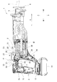
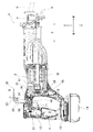
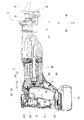
本発明の実施形態を図1ないし図13を参照しつつ説明する。図1及び図2に示すように充電式レシプロソー1はハウジング2を備えている。ハウジング2は、充電式レシプロソー1の前後方向X(図1及び図2の左右方向)に延設されて、ハウジング2の後端部にハンドル3が形成されている。なお充電式レシプロソー1は本発明の電動工具の一例である。
図2に示すように、ハウジング2内の前後方向Xにおける中央付近にはモータMが収容されている。そしてハウジング2の前端部(図1及び図2の右側)から、先端にツールホルダ5を有するスライダ(図示せず。)を、ハウジング2の前方へ突出させている。このツールホルダ5には、直線状の切断刃6(図2参照。)が、スライダと同一軸線方向へ取り付け可能である。またハウジング2の前部には、モータMの回転をスライダの軸線方向(図1及び図2の左右方向)への直線往復動に変換する往復動機構(図示せず。)が収容されている。加えてハウジング2の前端面には、ガイドシュー8がハウジング2と直交状に支持されている。このガイドシュー8には、その前後方向(図2の左右方向)に貫通する貫通孔9(図1参照。)が設けられて、切断刃6が貫通孔9を通じてガイドシュー8を貫通可能となっている。
ハンドル3は、図2に示すように側面視で略コの字状とされている。このハンドル3には、トリガ11を有するスイッチ12が収容されている。トリガ11は、ハンドル3の開口からハンドル3の外部に露出しており、ハンドル3内へ押し込み可能とされている。
図1及び図2に示すようにハンドル3の下端には、バッテリーパック装着部13が形成されている。このバッテリーパック装着部13にはバッテリーパック14が着脱自在に装着される。上記のトリガ11をハンドル3内に押し込むことでスイッチ12がオン状態になると、バッテリーパック14はモータMに電力を供給する。これによりモータMが回転して上記の往復動機構が動作すると、スライダと共に切断刃6が、スライダの軸線方向へ直線往復動して被切断材を切断する。
図1及び図2に示すようにハンドル3の上面には、充電式レシプロソー1を例えば壁に設けた係止部材に吊り下げるために用いるフック20が取り付けられている。図2に示すようにフック20は、金属製(例えばアルミニウム)の棒状体を略U字状に折り曲げて形成して、基端部21と、基端部21と対向して位置する係止部22と、基端部21と係止部22との間であって、基端部21の先端側から係止部22へ向かうように折り返された折り返し部23とで構成されている。基端部21は、後述するように球体24(図2参照。)と連結されている。
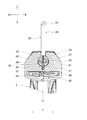
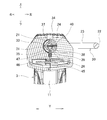
図1及び図2に示すようにハンドル3の上部には、ハンドル3の上面に開口して、金属製(例えば鉄製)の球体24を収容可能な収容空間25が形成されている。この収容空間25は前後方向Xに細長い形状とされている。収容空間25の底面で、前後方向Xと直交するハウジング2の左右方向Yの真中位置P(図3参照。)には、半球状の凹溝26(図2及び図3参照。)が設けられている。図2及び図3に示すように球体24は、凹溝26に挿入されることで前記真中位置Pに配置されることになる。そして球体24は、凹溝26に沿って回動可能とされている。
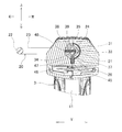
図4及び図7に示すように球体24は、該球体24の左右両側に延びて球体24の半周面に沿った半円状で、該半周面に凹設された第1ガイド溝31と、第1ガイド溝31の中央部と連設されて、前記半周面に沿って該中央部から球体24の前方向へ第1ガイド溝31と略直角に延びて、該半周面に凹設された第2ガイド溝32とを有している。図4に示すように、第1ガイド溝31の中央部には、該第1ガイド溝31に開口する第1係合凹部33が形成されている。また第1ガイド溝31の一端部には、該第1ガイド溝31に開口する第2係合凹部34、第1ガイド溝31の他端部には、該第1ガイド溝31に開口する第3係合凹部35がそれぞれ形成されている。さらに第2ガイド溝32の前端には、該第2ガイド溝32に開口する第4係合凹部36が形成されている。
さらに図3に示すように球体24は、周面に開口して該周面から球体24の中心に向けて延びる長孔37を有している。この長孔37には、フック20の基端部21が挿入可能とされている。加えて図2及び図3に示すように球体24は、周面に開口し前記長孔37との直交方向に延びて該長孔37に連通するピン導入孔38(図2参照。)を有している。また基端部21には、該基端部21の軸方向との直交方向で基端部21を貫通する貫通孔39(図3及び図7参照。)が形成されている。基端部21を長孔37に挿入すると、ピン導入孔38と貫通孔39とが連通する。この状態で位置決めピン40(図3及び図7参照。)をピン導入孔38に導入すると、位置決めピン40の先端側を貫通孔39に嵌入させることができる。このようにすることでフック20の基端部21は長孔37に抜け止めされて、フック20は球体24に連結されている。
一方、図2及び図3に示すように収容空間25の底面には、凹溝26の底中心に開口するコイルスプリング収容孔45が形成されている。このコイルスプリング収容孔45に収容されたコイルスプリング46は、略円柱状のロックピン47を球体24側へ付勢している。図2及び図3にはロックピン47が、コイルスプリング46の付勢力によって球体24の第4係合凹部36に係合している状態を示した。後述するようにロックピン47は、第4係合凹部36以外にも第1係合凹部33ないし第3係合凹部35(図4参照。)に係合自在とされている。なお、コイルスプリング46及びロックピン47は本発明の係合部の一例であり、第1係合凹部33ないし第4係合凹部36は本発明の被係合部の一例である。
また図1及び図2に示すようにハンドル3の上部には、ハンドル3の上面に開口し収容空間25の後端部と連続してハウジング2の左右方向Yに延びるスリット50が形成されている。このスリット50は、ハンドル3の左右の側面にも開口して、収容空間25と直交状に形成されている。スリット50は、後述するようにフック20の回動を許容するために、フック20の基端部21を収容空間25から逃がすために用いられる。さらに、前後方向Xにおけるハンドル3よりも前方位置には、ハウジング3の上面に開口する係止孔51が形成されている。この係止孔51には、以下に説明するように、フック20の係止部22の端部29(以下「係止端部29」という。)をハウジング2の上方から挿入して係止可能である。
次に本実施形態の充電式レシプロソー1においてフック20の位置を変更する操作を説明する。フック20を使用しない未使用位置に配置するときは、図2及び図3に示すようにロックピン47を、球体24の第4係合凹部36に係合させる。ロックピン47と第4係合凹部36とを係合させることで、球体24及びフック20の回動が阻止される。これにより、フック20を未使用位置に固定できる。未使用位置では図2に示すように、基端部21が起立状態で収容空間25から上方へ突出し、折り返し部23がハウジング2の上方で前後方向Xに配置され、係止端部29が、ハウジング2の上方から係止孔51に挿入係止されて該係止孔51に収容される状態を作り出すことができる。これに加えて図2に示すように係止端部29が係止孔51に挿入係止されたときには、フック20とハウジング2との間に係止開口53が形成されている。この係止開口53は、ハウジング2の上面とフック20とで囲まれた空間である。図2に示すように係止端部29は係止孔51に抜け止めできるため、例えば壁に設けた係止部材に係止開口53を係止すれば、充電式レシプロソー1を、係止開口53を介して該係止部材に吊り下げることが可能になる。
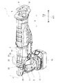
またフック20を、係止部22がハウジング2の上方に位置する上方位置(図5及び図7参照。)に配置する場合には以下の操作を行う。例えばフック20を未使用位置(図1及び図2参照。)から上方位置へ移動させる場合には、操作者は、係止端部29を係止孔51から引き上げる。すると、球体24の第2ガイド溝32(図4及び図6参照。)の底面で、ロックピン47がコイルスプリング46の付勢力に抗して押されることで第4係合凹部36(図6参照。)から抜け出る。その後も操作者が係止端部29を係止孔51から引き上げる操作を続けると、前記第2ガイド溝32は、ロックピン47を嵌め入れながら球体24が、該球体24の後方側(図6の左側)へ回動することを案内する。このときフック20の基端部21が収容空間25からスリット50に逃げることで、該フック20も、球体24を支点として前記後方側へ回動する。そして、球体24が回動することで図7に示すように、第2ガイド溝32と直交状に連設された第1ガイド溝31の第1係合凹部33がロックピン47と対向する位置に到達したときには、ロックピン47が、コイルスプリング46の付勢力によって第1係合凹部33と係合する。これにより、球体24及びフック20の回動が阻止されて、フック20を上方位置に固定できる。この上方位置では図6に示すように、折り返し部23が起立状態でスリット50から上方へ突出すると共に、係止部22がハウジング2の上方で前後方向Xに配置されている。例えば上方位置に固定されたフック20の係止部22を、水平方向に延びる建築設備の梁に係止することで、充電式レシプロソー1を横向き状態で梁に吊り下げることができる。
一方、フック20を使用する必要がなくなり、フック20を上方位置から前記未使用位置に移動させる場合には、操作者は、係止部22を球体24を支点としてハウジング2の前方側へ回動させる。すると、第2ガイド溝32の底面で、ロックピン47がコイルスプリング46の付勢力に抗して押されることで上記の第1係合凹部33から抜け出る。その後も操作者が係止部22を前記前方側へ回動させる操作を続けると、前記第2ガイド溝32は、ロックピン47を嵌め入れながら球体24が、該球体24の前方側(図6の右側)へ回動することを案内する。このときフック20の基端部21がスリット50から収容空間25に逃げることで、フック20も、球体24を支点として前記前方側へ回動する。そして、球体24が回動することで図3に示すように、第2ガイド溝32の第4係合凹部36がロックピン47と対向する位置に到達したときには、ロックピン47が第4係合凹部36と係合する。これにより、球体24及びフック20の回動が阻止されて、フック20を前記未使用位置に固定できる。
さらにフック20を、係止部22がハウジング2の左側に位置する左位置(図8及び図10参照。)へ配置する場合には以下の操作を行う。例えばフック20を上方位置(図5及び図6参照。)から左位置へ移動させる場合には、操作者は、係止部22を球体24を支点としてハウジング2の左側へ回動させる。すると、第1ガイド溝31(図4及び図10参照。)の底面で、ロックピン47がコイルスプリング46の付勢力に抗して押されることで第1係合凹部33(図7及び図10参照。)から抜け出る。その後も操作者が係止部22を前記左側へ回動させる操作を続けると、前記第1ガイド溝31は、ロックピン47を嵌めながら球体24が、該球体24の左側(図10の右側)へ回動することを案内する。このときフック20の折り返し部23が、図5及び図8から理解できるようにスリット50内に傾倒することで、フック20も、球体24を支点として前記左側へ回動する。そして、球体24が回動することで図10に示すように、第1ガイド溝31の第3係合凹部35がロックピン47と対向する位置に到達したときに、ロックピン47が第3係合凹部35と係合する。これにより、球体24及びフック20の回動が阻止されて、フック20を左位置に固定できる。この左位置では図8に示すように、折り返し部23がスリット50からハウジング2の左側へ突出すると共に、係止部22が該左側で前後方向Xに配置されている。例えば左位置に固定されたフック20の係止部22を、水平方向に延びる梁に右側から係止することで、充電式レシプロソー1を下向き状態で梁に吊り下げることができる。
加えてフック20を、係止部22がハウジング2の右側に位置する右位置(図11及び図12参照。)へ配置する場合には以下の操作を行う。例えばフック20を上方位置(図5及び図6参照。)から右位置へ移動させる場合には、操作者は、係止部22を球体24を支点としてハウジング2の右側へ回動させる。すると、フック20を上方位置から左位置へ移動させる場合と同様に、ロックピン47が第1係合凹部33から抜け出る。その後も操作者が係止部22を前記右側へ回動させる操作を続けると、前記第1ガイド溝31は、ロックピン47を嵌めながら球体24が、該球体24の右側(図12の左側)へ回動することを案内する。このときフック20の折り返し部23が、図5及び図11から理解できるようにスリット50内に傾倒することで、フック20も、球体24を支点として前記右側へ回動する。そして、球体24が回動することで図13に示すように、第1ガイド溝31の第2係合凹部34がロックピン47と対向する位置に到達したときに、ロックピン47が第2係合凹部34と係合する。これにより、球体24及びフック20の回動が阻止されて、フック20を右位置に固定できる。この右位置では図11に示すように、折り返し部23がスリット50からハウジング2の右側へ突出すると共に、係止部22が該右側で前後方向Xに配置されている。例えば右位置に固定されたフック20の係止部22を、水平方向に延びる梁に左側から係止することで、充電式レシプロソー1を下向き状態で梁に吊り下げることができる。
このように本実施形態では球体24は、第1ガイド溝31によって該球体24の左側及び右側に回動することが案内され、第2ガイド溝32によって該球体24の前後方向に回動することが案内される。そしてロックピン47を、第1ガイド溝31に形成した各係合凹部33~35と係合させることで、フック20を上方位置、右位置、左位置にそれぞれ固定できる。加えてロックピン47を、第2ガイド溝32に形成した第4係合凹部36と係合させることで、フック20を未使用位置に固定できることになる。なお、球体24の左右両側及び前後方向は、本発明の複数の異なる方向の一例であり、球体24の前方側への回動方向は、本発明のフックの係止端部がハウジングに挿入係止可能な方向の一例である。また、上方位置、右位置、左位置及び未使用位置は、本発明の複数の異なる方向における任意の位置の一例である。
<本実施形態の効果>
本実施形態の充電式レシプロソー1では、球体24の回動によるだけで、該球体24に連結したフック20を、複数の異なる方向(球体24の前後方向や球体24の左側及び右側)に回動させることが可能になる。よって、フック20を複数の異なる方向に配置するための操作を簡単に行うことができる。
本実施形態の充電式レシプロソー1では、球体24の回動によるだけで、該球体24に連結したフック20を、複数の異なる方向(球体24の前後方向や球体24の左側及び右側)に回動させることが可能になる。よって、フック20を複数の異なる方向に配置するための操作を簡単に行うことができる。
また、フック20を使用しない場合には球体24を、フック20の係止端部29がハウジング2の係止孔51に挿入係止可能な方向(球体24の前方側への回動方向)へ回動させることで、前記係止端部29をハウジング2の係止孔51に収容できる。
さらに、係止端部29が前記係止孔51に挿入係止されたときには、例えば壁に設けた係止部材に係止開口53を係止させることで、充電式レシプロソー1を該係止部材に吊り下げることが可能になる。
加えてハウジング2に設けたロックピン47を、コイルスプリング46の付勢力によって、球体24に形成した第1ないし第4係合凹部33~36と係合させる簡単な構造で、フック20を、上方位置、右位置、左位置、未使用位置にそれぞれ固定することが可能になる。
さらに加えて、フック20を連結した球体24を、ハンドル3の上部でハウジング2の左右方向Yの真中位置Pに配置したため、ハウジング2の左側及び右側(球体24の左側及び右側)への球体24の回動によって、フック20を、ハウジング2の左側及び右側へ簡単に配置可能となる。
本発明は、上述した実施形態に限定されるものではなく、発明の趣旨を逸脱しない範囲内において構成の一部を適宜変更して実施できる。例えば、上述した実施形態では第1ガイド溝31に3つの係合凹部33~35を形成したが、これに限らず、第1ガイド溝31に、ロックピン47と係合可能な4つ以上の係合凹部を形成し、フック20をハウジング2の左右方向Yで傾倒させる角度が複数選択できるようにしてもよい。
また、上述した実施形態では、ハウジング2側にコイルスプリング46とロックピン47とを配置し、球体24に各係合凹部33~36を形成したが、これに限らず、球体24側にコイルスプリン46とロックピン47とを配置して、ロックピン47と係合可能な複数の係合凹部をハウジング2側に形成してもよい。さらに、上述した実施形態では、本発明を充電式レシプロソーに適用する例を示したが、これに限らず本発明を交流駆動式のレシプロソーや充電式又は交流駆動式のハンマドリル等の電動工具に適用してもよい。
1・・充電式レシプロソー、2・・ハウジング、3・・ハンドル、6・・切断刃、20・・フック、24・・球体、33・・第1係合凹部、34・・第2係合凹部、35・・第3係合凹部、36・・第4係合凹部、46・・コイルスプリング、47・・ロックピン、53・・係止開口、M・・モータ、P・・ハウジングの左右方向の真中位置、X・・ハウジングの前後方向、Y・・ハウジングの左右方向。
Claims (11)
- 電動工具のハウジングに、吊り下げ用のフックを取り付ける電動工具におけるフックの取付構造であって、
前記ハウジングに、複数の異なる方向へ回動可能な球体を配置して、該球体に前記フックを連結したことを特徴とする電動工具におけるフックの取付構造。 - 前記複数の異なる方向の一つを、前記フックの係止端部が前記ハウジングに挿入係止可能な方向としたことを特徴とする請求項1に記載の電動工具におけるフックの取付構造。
- 前記係止端部が前記ハウジングに前記挿入係止されたときに、前記フックと前記ハウジングとの間に係止開口が形成されることを特徴とする請求項2に記載の電動工具におけるフックの取付構造。
- 前記ハウジングと前記球体との内の一方に、係合部を形成すると共に、他方に、前記複数の異なる方向に沿って前記係合部が係合自在な被係合部を複数形成して、
前記球体の回動に伴って前記係合部を各前記被係合部に係合させることにより、前記フックを、前記複数の異なる方向における任意の位置に固定自在としたことを特徴とする請求項1に記載の電動工具におけるフックの取付構造。 - 前記電動工具はレシプロソーであることを特徴とする請求項1に記載の電動工具におけるフックの取付構造。
- 前記レシプロソーは、前記ハウジングが前後方向に延設されてモータを収容し、前記ハウジングの前端部から前方へ突出して、前記モータの駆動で往復動し被切断材を切断する直線状の切断刃と、前記ハウジングの後端部に形成されたハンドルと、を備え、
前記ハンドルの上部で、前記前後方向と直交する左右方向の真中位置に、前記フックを連結した前記球体を配置したことを特徴とする請求項5に記載の電動工具におけるフックの取付構造。 - 前記ハンドルの上部に、前記真中位置を含む範囲で前記ハンドルの上面に開口して前記球体を収容可能な収容空間を形成して、前記収容空間の底面で前記真中位置に、前記球体を回動可能に配置する半球状の凹溝を設けたことを特徴とする請求項6に記載の電動工具におけるフックの取付構造。
- 前記球体は、前記球体の左右両側に延びて前記球体の半周面に沿った半円状で、該半周面に凹設された第1ガイド溝と、前記第1ガイド溝の中央部と連設され、前記半周面に沿って該中央部から前記球体の前方向へ前記第1ガイド溝と直角に延びて前記半周面に凹設された第2ガイド溝と、を備え、
前記係合部を、前記凹溝の底中心に開口させたコイルスプリング収容孔に収容したコイルスプリングと、前記コイルスプリングによって前記球体側へ付勢される略円柱状のロックピンと、で構成し、
前記被係合部を、前記第1ガイド溝の中央部に開口する第1係合凹部と、前記第1ガイド溝の一端部に開口する第2係合凹部と、前記第1ガイド溝の他端部に開口する第3係合凹部と、前記第2ガイド溝の前端に開口する第4係合凹部と、で構成して、
前記球体が回動する際に、前記ロックピンは、前記第1ガイド溝に嵌め入れられて案内された前記第1ないし前記第3係合凹部に、前記コイルスプリングの付勢力によってそれぞれ係合可能であると共に、
前記球体が回動する際に、前記ロックピンは、前記第2ガイド溝に嵌め入れられて案内された前記第4係合凹部に、前記コイルスプリングの付勢力によって係合可能であることを特徴とする請求項7に記載の電動工具におけるフックの取付構造。 - 前記球体に、周面に開口して該周面から前記球体の中心に向けて延びて、前記フックの基端部を挿入可能な長孔と、前記周面に開口し前記長孔との直交方向に延びて前記長孔に貫通するピン導入孔と、を形成し、
前記フックの基端部に、前記基端部の軸方向との直交方向で前記基端部を貫通する貫通孔を形成して、
前記基端部を前記長孔に挿入して、前記ピン導入孔と前記貫通孔とを連通させ、前記貫通孔に、前記ピン導入孔に導入した位置決めピンの先端側を嵌入させて、前記球体に前記フックを連結したことを特徴とする請求項1に記載の電動工具におけるフックの取付構造。 - 前記ハウジングの上面には、前記球体を前記フックの係止端部が前記ハウジングに挿入係止可能な方向に回動させたときに、前記係止端部を前記ハウジングの上方から挿入して係止可能な係止孔を開口させたことを特徴とする請求項2に記載の電動工具におけるフックの取付構造。
- 前記複数の異なる方向は、前記フックの係止端部を前記ハウジングの左側に移動させる左方向と、前記係止端部を前記ハウジングの右側に移動させる右方向と、前記係止端部を前記ハウジングの上方に移動させる上方向と、を含み、
前記第1ガイド溝は、前記ロックピンを嵌め入れながら前記球体を該球体の左側又は右側へ回動させることで、前記係止端部を前記左方向又は前記右方向へ移動させ、
前記第2ガイド溝は、前記ロックピンを嵌め入れながら前記球体を該球体の後方側へ回動させることで、前記係止端部を前記上方向へ移動させることを特徴とする請求項8に記載の電動工具におけるフックの取付構造。
Applications Claiming Priority (2)
| Application Number | Priority Date | Filing Date | Title |
|---|---|---|---|
| JP2012-163934 | 2012-07-24 | ||
| JP2012163934A JP2014024126A (ja) | 2012-07-24 | 2012-07-24 | 電動工具におけるフックの取付構造 |
Publications (1)
| Publication Number | Publication Date |
|---|---|
| WO2014017113A1 true WO2014017113A1 (ja) | 2014-01-30 |
Family
ID=49996933
Family Applications (1)
| Application Number | Title | Priority Date | Filing Date |
|---|---|---|---|
| PCT/JP2013/055381 Ceased WO2014017113A1 (ja) | 2012-07-24 | 2013-02-28 | 電動工具におけるフックの取付構造 |
Country Status (2)
| Country | Link |
|---|---|
| JP (1) | JP2014024126A (ja) |
| WO (1) | WO2014017113A1 (ja) |
Cited By (1)
| Publication number | Priority date | Publication date | Assignee | Title |
|---|---|---|---|---|
| WO2023020744A1 (de) * | 2021-08-20 | 2023-02-23 | Robert Bosch Gmbh | Handgehaltenes bearbeitungsgerät mit einer aufhängevorrichtung |
Families Citing this family (7)
| Publication number | Priority date | Publication date | Assignee | Title |
|---|---|---|---|---|
| US10027201B2 (en) | 2015-04-01 | 2018-07-17 | Makita Corporation | Reciprocating tool |
| JP6639797B2 (ja) * | 2015-04-01 | 2020-02-05 | 株式会社マキタ | レシプロソー |
| JP6863704B2 (ja) | 2016-10-07 | 2021-04-21 | 株式会社マキタ | 打撃工具 |
| US10875168B2 (en) | 2016-10-07 | 2020-12-29 | Makita Corporation | Power tool |
| JP7246202B2 (ja) | 2019-02-19 | 2023-03-27 | 株式会社マキタ | 震動機構付き電動工具 |
| JP7229807B2 (ja) | 2019-02-21 | 2023-02-28 | 株式会社マキタ | 電動工具 |
| JP7490466B2 (ja) | 2020-06-23 | 2024-05-27 | 株式会社マキタ | 締結工具 |
Citations (5)
| Publication number | Priority date | Publication date | Assignee | Title |
|---|---|---|---|---|
| JPH0838341A (ja) * | 1994-07-27 | 1996-02-13 | Dia Corp:Kk | 物品吊下具 |
| JP2001191269A (ja) * | 1999-12-28 | 2001-07-17 | Ryobi Ltd | 電動工具におけるフックの取付構造 |
| JP2004351538A (ja) * | 2003-05-27 | 2004-12-16 | Matsushita Electric Works Ltd | フック付き可搬式電動工具 |
| JP2009095917A (ja) * | 2007-10-16 | 2009-05-07 | Hitachi Koki Co Ltd | 動力工具 |
| JP2012085557A (ja) * | 2010-10-18 | 2012-05-10 | Okada Kinzoku Kogyosho:Kk | 枝打レシプロソー |
-
2012
- 2012-07-24 JP JP2012163934A patent/JP2014024126A/ja active Pending
-
2013
- 2013-02-28 WO PCT/JP2013/055381 patent/WO2014017113A1/ja not_active Ceased
Patent Citations (5)
| Publication number | Priority date | Publication date | Assignee | Title |
|---|---|---|---|---|
| JPH0838341A (ja) * | 1994-07-27 | 1996-02-13 | Dia Corp:Kk | 物品吊下具 |
| JP2001191269A (ja) * | 1999-12-28 | 2001-07-17 | Ryobi Ltd | 電動工具におけるフックの取付構造 |
| JP2004351538A (ja) * | 2003-05-27 | 2004-12-16 | Matsushita Electric Works Ltd | フック付き可搬式電動工具 |
| JP2009095917A (ja) * | 2007-10-16 | 2009-05-07 | Hitachi Koki Co Ltd | 動力工具 |
| JP2012085557A (ja) * | 2010-10-18 | 2012-05-10 | Okada Kinzoku Kogyosho:Kk | 枝打レシプロソー |
Cited By (2)
| Publication number | Priority date | Publication date | Assignee | Title |
|---|---|---|---|---|
| WO2023020744A1 (de) * | 2021-08-20 | 2023-02-23 | Robert Bosch Gmbh | Handgehaltenes bearbeitungsgerät mit einer aufhängevorrichtung |
| US12358119B2 (en) | 2021-08-20 | 2025-07-15 | Robert Bosch Gmbh | Handheld processing tool having a suspension means |
Also Published As
| Publication number | Publication date |
|---|---|
| JP2014024126A (ja) | 2014-02-06 |
Similar Documents
| Publication | Publication Date | Title |
|---|---|---|
| WO2014017113A1 (ja) | 電動工具におけるフックの取付構造 | |
| US10286539B2 (en) | Dual axis hook assembly for a power tool | |
| US9457461B2 (en) | Dual axis hook assembly for a power tool | |
| JP5352153B2 (ja) | 充電式電動工具 | |
| JP6300271B2 (ja) | チェーンソー | |
| US20150041166A1 (en) | Modular electro-mechanical device | |
| CN101970180B (zh) | 用于自动钉枪的导线部 | |
| JP2017159419A (ja) | 先端工具ホルダおよび電動工具 | |
| US11684985B2 (en) | Portable cutting machine | |
| JP5416649B2 (ja) | 電動工具及び電動工具用吊り下げ具 | |
| JP2019096417A (ja) | バッテリ装置 | |
| JP5360345B2 (ja) | 動力工具 | |
| JP2017189824A (ja) | 回転工具 | |
| JP2016175148A (ja) | 電動工具 | |
| JP2009028841A (ja) | 電動工具のフック構造 | |
| JP4773586B2 (ja) | 充電式電動工具用の吊り下げ具 | |
| JP6808537B2 (ja) | 手持ち工具のフック | |
| JP4383750B2 (ja) | 充電式電動工具におけるフックの取付構造 | |
| JP2017105206A (ja) | チェーンソー | |
| JP4672438B2 (ja) | 携帯工具のフック | |
| JP3189172U (ja) | 工具用ホルダー | |
| CN210525155U (zh) | 工具刀 | |
| JP5698035B2 (ja) | 電動工具 | |
| JP3184315U (ja) | 往復動切断工具 | |
| KR20160003420U (ko) | 슬라이드 이동이 가능한 고정걸이를 갖는 전동 공구 |
Legal Events
| Date | Code | Title | Description |
|---|---|---|---|
| 121 | Ep: the epo has been informed by wipo that ep was designated in this application |
Ref document number: 13823789 Country of ref document: EP Kind code of ref document: A1 |
|
| NENP | Non-entry into the national phase |
Ref country code: DE |
|
| 122 | Ep: pct application non-entry in european phase |
Ref document number: 13823789 Country of ref document: EP Kind code of ref document: A1 |