WO2014010694A1 - コネクタ - Google Patents
コネクタ Download PDFInfo
- Publication number
- WO2014010694A1 WO2014010694A1 PCT/JP2013/069029 JP2013069029W WO2014010694A1 WO 2014010694 A1 WO2014010694 A1 WO 2014010694A1 JP 2013069029 W JP2013069029 W JP 2013069029W WO 2014010694 A1 WO2014010694 A1 WO 2014010694A1
- Authority
- WO
- WIPO (PCT)
- Prior art keywords
- electric wire
- terminal
- connector
- covered
- covered electric
- Prior art date
- Legal status (The legal status is an assumption and is not a legal conclusion. Google has not performed a legal analysis and makes no representation as to the accuracy of the status listed.)
- Ceased
Links
Images



Classifications
-
- H—ELECTRICITY
- H01—ELECTRIC ELEMENTS
- H01R—ELECTRICALLY-CONDUCTIVE CONNECTIONS; STRUCTURAL ASSOCIATIONS OF A PLURALITY OF MUTUALLY-INSULATED ELECTRICAL CONNECTING ELEMENTS; COUPLING DEVICES; CURRENT COLLECTORS
- H01R13/00—Details of coupling devices of the kinds covered by groups H01R12/70 or H01R24/00 - H01R33/00
- H01R13/58—Means for relieving strain on wire connection, e.g. cord grip, for avoiding loosening of connections between wires and terminals within a coupling device terminating a cable
- H01R13/5845—Means for relieving strain on wire connection, e.g. cord grip, for avoiding loosening of connections between wires and terminals within a coupling device terminating a cable the strain relief being achieved by molding parts around cable and connections
-
- H—ELECTRICITY
- H01—ELECTRIC ELEMENTS
- H01R—ELECTRICALLY-CONDUCTIVE CONNECTIONS; STRUCTURAL ASSOCIATIONS OF A PLURALITY OF MUTUALLY-INSULATED ELECTRICAL CONNECTING ELEMENTS; COUPLING DEVICES; CURRENT COLLECTORS
- H01R13/00—Details of coupling devices of the kinds covered by groups H01R12/70 or H01R24/00 - H01R33/00
- H01R13/46—Bases; Cases
- H01R13/502—Bases; Cases composed of different pieces
- H01R13/504—Bases; Cases composed of different pieces different pieces being moulded, cemented, welded, e.g. ultrasonic welding, or swaged together
-
- H—ELECTRICITY
- H01—ELECTRIC ELEMENTS
- H01R—ELECTRICALLY-CONDUCTIVE CONNECTIONS; STRUCTURAL ASSOCIATIONS OF A PLURALITY OF MUTUALLY-INSULATED ELECTRICAL CONNECTING ELEMENTS; COUPLING DEVICES; CURRENT COLLECTORS
- H01R13/00—Details of coupling devices of the kinds covered by groups H01R12/70 or H01R24/00 - H01R33/00
- H01R13/46—Bases; Cases
- H01R13/52—Dustproof, splashproof, drip-proof, waterproof, or flameproof cases
-
- H—ELECTRICITY
- H01—ELECTRIC ELEMENTS
- H01R—ELECTRICALLY-CONDUCTIVE CONNECTIONS; STRUCTURAL ASSOCIATIONS OF A PLURALITY OF MUTUALLY-INSULATED ELECTRICAL CONNECTING ELEMENTS; COUPLING DEVICES; CURRENT COLLECTORS
- H01R13/00—Details of coupling devices of the kinds covered by groups H01R12/70 or H01R24/00 - H01R33/00
- H01R13/46—Bases; Cases
- H01R13/52—Dustproof, splashproof, drip-proof, waterproof, or flameproof cases
- H01R13/5205—Sealing means between cable and housing, e.g. grommet
Definitions
- the present invention relates to a connector.
- an electric wire is covered with a soft resin material, and further, this soft resin material is covered with a hard resin material housing (Patent Document 1). reference).
- a conductive cylinder 507 is fixed in a conductive state to a conductive flange 505 that can be fixed to the shield wall 503 in a conductive state. It is electrically connected to the shield layer 511 at 509.
- a waterproof cylindrical body 515 made of a soft resin (urethane resin or the like) is molded in a form of being fitted around the sheath 513 of the shielded electric wire 509.
- a housing 519 made of hard resin is molded in a form that is fitted around the waterproof cylinder 515, the sheath 513, the shield layer 511, and the core 517.
- an O-ring 521 is attached to the outer periphery of the housing 519.
- the waterproof cylinder 515 provided so as to cover the boundary between the housing 519 and the shielded electric wire 509 keeps the watertightness between the inner surface of the housing 519 and the outer surface of the shielded electric wire 509. Thus, it is possible to prevent liquid such as water from entering the housing through the shielded electric wire 509.
- the shield connector 501 in which the waterproof tube 515 made of a relatively flexible urethane resin is externally mounted on the end portion of the shielded electric wire 509 and the waterproof tube 515 is covered with the tubular housing 519, the shield connector 501 is exposed from the housing 519. If the waterproof cylinder 515 of the portion that has been deformed follows the shielded electric wire 509 and the adhesive strength with the sheath 513 is low, peeling may occur at the interface between the exposed portion of the waterproof cylinder 515 and the sheath 513 There is. If peeling occurs at the interface between the waterproof cylinder 515 and the sheath 513, the waterproof performance may be impaired.
- the present invention has been made in view of the above situation, and an object of the present invention is to provide a highly reliable connector with respect to a waterproof function by suppressing interfacial peeling caused by electric wire bending.
- the above object of the present invention is achieved by the following configuration.
- (1) The terminal fixed to the conductor exposed to the terminal portion of the covered electric wire, and the adjacent portions of the plurality of terminals provided side by side and the respective coverings of the covered electric wire are integrally covered, and via the connecting portion
- the entire seal portion at the end portion of the covered electric wire is covered with the insulating resin. Therefore, the stress of the electric wire bending is not transmitted to the interface between the covering of the covered electric wire and the seal portion, and interface peeling can be suppressed.
- the connection part of a seal part can mutually position between the terminal parts of the some covered electric wire to which the terminal was fixed. Therefore, since the seal parts that are primarily molded at the terminal portions of the plurality of covered wires are covered with the housing, the terminal portions of the plurality of covered wires to which the terminals are fixed are molded even when the insulating resin is secondarily formed. Positioning can be accurately performed in the cavity, and workability during molding can be improved, and a connector with good dimensional accuracy can be obtained.
- the axial distance between the seal portions is constant, high parallelism is obtained, and mutual positioning is more stable.
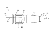
- FIG. 1 is a plan view of a connector according to an embodiment of the present invention.
- FIG. 2 is a side view of the connector shown in FIG. 3 is a plan view of the connector shown in FIG. 1 with the housing removed.
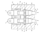
- FIG. 4 is a horizontal sectional view of an injection mold for molding the housing shown in FIG.
- FIG. 5 is a longitudinal sectional view of a conventional connector.
- a terminal 17 is connected to a conductor 15 of a covered electric wire 13, and a terminal portion 18 of the covered electric wire 13 and a part of the terminal 17 are connected portions thereof.
- the connector 11 will be described with the terminal side as the front and the covered wire side as the rear.
- the covered wire 13 in which the conductor 15 is covered with the covering 19 is connected to the connector 11 of the present embodiment.
- the covered electric wire according to the present invention in addition to the covered electric wire 13 in which the conductor 15 is covered only by the covering 19, the outer side of the inner insulating coating covering the conductor is covered by a metal braid, and the outer side is covered by the jacket. A shielded wire may be used.
- the connector 11 of the present embodiment is provided for a plurality (two in the present embodiment) of the covered electric wires 13 in which the terminals 17 are connected to the conductors 15 together.
- the terminal 17 is connected and fixed to the conductor 15 exposed at the terminal portion 18 of the covered electric wire 13.
- the connection structure between the terminal 17 and the conductor 15 may be any of a crimping structure, a pressure welding structure, a welding structure, a brazing structure, and the like.
- the terminal 17 illustrates the flat terminal which is a male terminal
- the terminal 17 is a female terminal which has a box-shaped electrical contact part other than a round terminal, a Y-shaped terminal, etc. Also good.
- the conductor 15 and the terminal portion 18 of the covered electric wire 13 are primarily formed as a sealing portion 21 with an insulating elastic material such as a thermoplastic elastomer (see FIG. 3), and then the sealing portion 21 and the terminal portion 18.
- an insulating elastic material such as a thermoplastic elastomer (see FIG. 3)
- the seal portion 21 is formed of a thermoplastic elastomer, and integrally covers adjacent portions 28 of the two terminals 17 and the coverings 19 of the two covered electric wires 13 that are provided apart from each other, and is connected via a connecting portion 27. Link them together.
- a material that can easily bond the covering 19 of the covered electric wire 13 and the housing 23 is selected.
- thermoplastic elastomer By modifying the thermoplastic elastomer, it can be thermally bonded to a thermoplastic resin having a high polarity value such as ordinary polycarbonate and ABS resin, and has excellent flexibility and moldability. It becomes possible.
- a plurality (two in the present embodiment) of the connecting portions 27 are arranged along the longitudinal direction of the covered electric wire 13.
- the seal portion 21 is formed with a flange portion 29 on the covered electric wire side and a terminal mold portion 31 on the terminal side.
- a constricted portion 33 having a smaller diameter than the terminal mold portion 31 and the flange portion 29 is formed in the seal portion 21 between the terminal mold portion 31 and the flange portion 29.
- a waterproof cylinder 35 that covers the outer periphery of the covered electric wire 13 is formed on the sealed portion 21 on the covered electric wire side of the flange portion 29.
- the adjacent flange portions 29 and the adjacent terminal mold portions 31 are connected to each other by a connecting portion 27.
- the housing 23 is formed of an insulating resin having rigidity higher than that of the elastic material forming the seal portion 21, and integrally covers the entire seal portion 21 in the terminal portion 18 of the covered electric wire 13. That is, the housing 23 covers all of the terminal mold part 31, the flange part 29, and the waterproof cylinder 35 of the two seal parts 21 provided side by side.
- the housing 23 has substantially the same thickness and is formed along the contours of the terminal mold part 31, the flange part 29 and the waterproof cylinder 35, and a solid block between the terminal mold part 31 and the flange part 29. It is formed as a housing body 37 having a shape (see FIG. 1).
- the electrical contact portion 39 of the terminal 17 protrudes toward the front, and a pair of waterproof cylinders 35 in a state covered with the housing 23 protrudes toward the rear.
- the covered electric wire 13 is led out from the waterproof cylinder 35. Since the waterproof cylinder 35 is covered with the housing 23, as a result, the covered electric wire 13 is directly led out from the waterproof cylinder covering portion 41 of the housing 23.
- the rear end of the waterproof cylinder covering part 41 is a small diameter part 43, thereby forming a stepped part 45.
- the small diameter portion 43 covering the outer periphery of the covered electric wire 13 is formed thin.
- the thin-walled small-diameter portion 43 is provided, thereby ensuring high adhesion with the covered electric wire 13.
- the small diameter portion 43 is made of a thermoplastic resin having rigidity higher than that of the thermoplastic elastomer, but has a certain degree of followability with respect to the bending of the wire by being formed into a thin wall.
- This followability is in a range that does not cause interface peeling between the waterproof cylinder 35 and the covered electric wire 13. That is, the small-diameter portion 43 suppresses the covered wire 13 while allowing the covered wire 13 to be bent within a range in which the interface peeling between the waterproof cylinder 35 and the covered wire 13 does not occur.
- the covered wire 13 having the terminal 17 fixed to the conductor 15 is set in a primary molding die (not shown), and the seal portion 21 shown in FIG. 3 is formed by primary molding.
- the covered electric wire 13 provided with the seal portion 21 is inserted into the cavity 46 of the secondary molding die (injection molding die) 47 shown in FIG. Secondary molding is performed with resin, and the housing 23 shown in FIG. 1 is molded. That is, the seal portion 21 is formed of a thermoplastic elastomer that is an elastic material, and the housing 23 is formed of a thermoplastic resin that is an insulating resin.
- the pair of seal portions 21 connected by the connecting portion 27 can mutually position the end portions 18 of the two covered electric wires 13 to which the terminals 17 are fixed. Therefore, since the seal portions 21 that are primarily molded on the end portions 18 of the two covered wires 13 are covered with the housing 23, the covered wires 13 to which the terminals 17 are fixed even when the insulating resin is secondarily formed.
- the end portion 18 can be accurately positioned in the cavity 46 of the secondary molding die 47. That is, the workability at the time of molding for setting the end portion 18 of the covered electric wire 13 in the cavity 46 is improved, and the end portion 18 of the covered electric wire 13 inserted into the cavity 46 is injected with a secondary molding resin (insulating resin).
- the connector 11 with good dimensional accuracy can be obtained without causing unevenness due to the pressure and non-uniform thickness of the housing 23.
- the entire seal portion 21 in the terminal portion 18 of the covered electric wire 13 is covered with an insulating resin. Therefore, the stress of the electric wire bending is not transmitted to the interface between the coating 19 and the seal portion 21, and the interface peeling can be suppressed.
- the connection part 27 of the seal part 21 can mutually position between the terminal parts 18 of the two covered electric wires 13 to which the terminals 17 are fixed. Therefore, since the seal portions 21 that are primarily molded on the terminal portions 18 of the two covered wires 13 are covered with the housing 23, the two terminals 17 that are fixed to the terminal 17 are also formed when the insulating resin is secondarily molded.
- the terminal portion 18 of the covered electric wire 13 can be accurately positioned in the cavity 46 of the secondary molding die 47, so that the workability at the time of molding is improved and the connector 11 with good dimensional accuracy can be obtained.
- connection part 27 since the axial space
- the mutual positioning between 18 is more stable.
- the flange portion 29 and the terminal mold portion 31 which are adjacent portions of the adjacent seal portions 21 are connected by the connecting portion 27, and the length of the connecting portion 27 is the shortest length. Is formed. Thereby, the connection part 27 becomes difficult to deform
- the connector 11 according to the present embodiment, interfacial peeling between the housing 23 and the seal portion 21 and the seal portion 21 and the coating 19 that are generated by bending the wire is suppressed, and the waterproof function is reliable. A highly connector 11 can be obtained.
- the terminal 17 fixed to the conductor 15 exposed at the terminal portion 18 of the covered electric wire 13 and the adjacent portions 28 of the plurality of the terminals 17 and the covering 19 of the covered electric wire 13 are integrated.
- the connector 11 having the configuration of [1], wherein a plurality of the connecting portions 27 are arranged along the longitudinal direction of the covered electric wire 13.
- the connector of this invention is not limited to embodiment mentioned above, A deformation
- the material, shape, dimensions, number, arrangement location, and the like of each component in the above-described embodiment are arbitrary and are not limited as long as the present invention can be achieved. This application is based on a Japanese patent application filed on July 11, 2012 (Japanese Patent Application No. 2012-155558), the contents of which are incorporated herein by reference.
- the connector according to the present invention it is possible to suppress interface peeling caused by electric wire bending and to obtain a highly reliable connector with respect to a waterproof function.
Landscapes
- Connector Housings Or Holding Contact Members (AREA)
Description
図5に示すように、シールドコネクタ501は、シールド壁503に対して導通状態での固定を可能とされた導電フランジ505に、導電筒507が導通状態で固定され、この導電筒507がシールド電線509のシールド層511に導通するものである。そこで、先ず、金型(図示せず)による第1成形工程において、シールド電線509のシース513に外嵌する形態で軟質樹脂製(ウレタン樹脂等)の防水筒体515が成形される。その後、第2成形工程において、防水筒体515、シース513、シールド層511およびコア517に外嵌する形態で硬質樹脂製のハウジング519が成形される。そして最後に、ハウジング519の外周にOリング521が装着される。このシールドコネクタ501によれば、ハウジング519とシールド電線509との境界部を覆うように設けられた防水筒体515が、これらハウジング519の内面とシールド電線509の外面との間を水密に保つので、シールド電線509を伝ってハウジング内に水などの液体が浸入することを防止できる。
(1) 被覆電線の端末部に露出された導体に固定される端子と、併設された複数の前記端子と前記被覆電線の被覆のそれぞれとの隣接部分を一体に覆うと共に、連結部を介してこれらを連結する絶縁性の弾性材料により形成されるシール部と、前記被覆電線の端末部における前記シール部の全体を一体に覆う前記弾性材料より剛性が高い絶縁樹脂により形成されるハウジングと、を備えるコネクタ。
図1及び図2に示すように、本実施形態に係るコネクタ11は、被覆電線13の導体15に端子17が接続され、その接続部分である被覆電線13の端末部18と端子17の一部分とが樹脂成形品にて覆われた所謂オーバーモールドコネクタである。なお、本明細書中において、コネクタ11は、端子側を前、被覆電線側を後として説明する。
シール部21は、熱可塑性エラストマーにより形成され、離間して併設された二つの端子17と2本の被覆電線13の被覆19のそれぞれとの隣接部分28を一体に覆うと共に、連結部27を介してこれらを連結する。熱可塑性エラストマーとしては、被覆電線13の被覆19とハウジング23とを接着し易い材料が選定される。
一次成形にてシール部21が形成された後、シール部21を備えた被覆電線13が、図4に示した二次成形金型(射出成形金型)47のキャビティ46にインサートされて、絶縁樹脂により二次成形が行われ、図1に示したハウジング23がモールド成形される。つまり、シール部21は弾性材料である熱可塑性エラストマーにて形成され、ハウジング23は絶縁樹脂である熱可塑性樹脂にて形成される。
上記のコネクタ11は、被覆電線13の端末部18におけるシール部21の全体が絶縁樹脂で覆われる。そこで、電線屈曲の応力が被覆19とシール部21との界面まで伝わらず、界面剥離を抑制できる。
また、シール部21の連結部27は、端子17が固定された2本の被覆電線13の端末部18間を相互位置決めすることができる。そこで、2本の被覆電線13の端末部18にそれぞれ一次成形されたシール部21がハウジング23で覆われる為、絶縁樹脂が二次成形される際にも、端子17が固定された2本の被覆電線13の端末部18を二次成形金型47のキャビティ46内で正確に位置決めすることができ、モールド成形時の作業性が向上すると共に寸法精度の良好なコネクタ11を得ることができる。
更に、本実施形態のコネクタ11は、隣接するシール部21の近接部位同士であるフランジ部29と端子モールド部31とが連結部27によって連結されており、連結部27の長さが最短長で形成されている。これにより、連結部27が変形し難くなり、連結部27の変形によるシール部21同士の相対位置変位を小さく抑制できる。
[1] 被覆電線13の端末部18に露出された導体15に固定される端子17と、併設された複数の前記端子17と前記被覆電線13の被覆19のそれぞれとの隣接部分28を一体に覆うと共に、連結部27を介してこれらを連結する絶縁性の弾性材料により形成されるシール部21と、前記被覆電線13の端末部18における前記シール部21の全体を一体に覆う前記弾性材料より剛性が高い絶縁樹脂により形成されるハウジング23と、を備えるコネクタ11。
[2] 上記[1]の構成のコネクタ11であって、前記連結部27が、前記被覆電線13の長手方向に沿って複数配置されるコネクタ11。
また、本出願は、2012年7月11日出願の日本特許出願(特願2012-155558)に基づくものであり、その内容はここに参照として取り込まれる。
13…被覆電線
15…導体
17…端子
18…端末部
19…被覆
21…シール部
23…ハウジング
27…連結部
29…フランジ部
31…端子モールド部
Claims (2)
- 被覆電線の端末部に露出された導体に固定される端子と、
併設された複数の前記端子と前記被覆電線の被覆のそれぞれとの隣接部分を一体に覆うと共に、連結部を介してこれらを連結する絶縁性の弾性材料により形成されるシール部と、
前記被覆電線の端末部における前記シール部の全体を一体に覆う前記弾性材料より剛性が高い絶縁樹脂により形成されるハウジングと、を備えるコネクタ。 - 請求項1に記載のコネクタであって、
前記連結部が、前記被覆電線の長手方向に沿って複数配置されるコネクタ。
Priority Applications (4)
| Application Number | Priority Date | Filing Date | Title |
|---|---|---|---|
| GB1500040.9A GB2517637A (en) | 2012-07-11 | 2013-07-11 | Connector |
| DE112013003480.8T DE112013003480T5 (de) | 2012-07-11 | 2013-07-11 | Verbinder |
| US14/413,943 US20150214655A1 (en) | 2012-07-11 | 2013-07-11 | Connector |
| CN201380037163.0A CN104471798A (zh) | 2012-07-11 | 2013-07-11 | 连接器 |
Applications Claiming Priority (2)
| Application Number | Priority Date | Filing Date | Title |
|---|---|---|---|
| JP2012-155558 | 2012-07-11 | ||
| JP2012155558A JP5941361B2 (ja) | 2012-07-11 | 2012-07-11 | コネクタ |
Publications (1)
| Publication Number | Publication Date |
|---|---|
| WO2014010694A1 true WO2014010694A1 (ja) | 2014-01-16 |
Family
ID=49916135
Family Applications (1)
| Application Number | Title | Priority Date | Filing Date |
|---|---|---|---|
| PCT/JP2013/069029 Ceased WO2014010694A1 (ja) | 2012-07-11 | 2013-07-11 | コネクタ |
Country Status (6)
| Country | Link |
|---|---|
| US (1) | US20150214655A1 (ja) |
| JP (1) | JP5941361B2 (ja) |
| CN (1) | CN104471798A (ja) |
| DE (1) | DE112013003480T5 (ja) |
| GB (1) | GB2517637A (ja) |
| WO (1) | WO2014010694A1 (ja) |
Families Citing this family (10)
| Publication number | Priority date | Publication date | Assignee | Title |
|---|---|---|---|---|
| JP2015207373A (ja) * | 2014-04-17 | 2015-11-19 | 日立金属株式会社 | 防水コネクタ及びその製造方法 |
| JP6551138B2 (ja) * | 2015-10-15 | 2019-07-31 | 住友電装株式会社 | コネクタ |
| JP6567600B2 (ja) | 2017-06-16 | 2019-08-28 | 矢崎総業株式会社 | コネクタ |
| DE102019204226B4 (de) | 2019-03-27 | 2022-06-09 | Hanon Systems Efp Deutschland Gmbh | Stecker füreine Steckverbindung an einer elektrischen Einheit, sowie Verfahren zur Herstel-lung eines Steckers für eine Steckverbindung an einer elektrischen Einheit |
| JP7005119B2 (ja) * | 2019-07-29 | 2022-01-21 | 矢崎総業株式会社 | コネクタ |
| JP7041101B2 (ja) * | 2019-08-07 | 2022-03-23 | 矢崎総業株式会社 | コネクタ |
| JP7066661B2 (ja) * | 2019-08-07 | 2022-05-13 | 矢崎総業株式会社 | コネクタ |
| US12470003B2 (en) * | 2020-08-26 | 2025-11-11 | Sumitomo Wiring Systems, Ltd. | Molded connector |
| JP7339299B2 (ja) * | 2021-06-21 | 2023-09-05 | 矢崎総業株式会社 | コネクタ |
| DE102021129840A1 (de) | 2021-11-16 | 2023-05-17 | BRUSS Sealing Systems GmbH | Elektrischer Leiter für die Leitung elektrischen Stroms durch ein Gehäuse und Verfahren zur Herstellung |
Citations (2)
| Publication number | Priority date | Publication date | Assignee | Title |
|---|---|---|---|---|
| JP2008269858A (ja) * | 2007-04-18 | 2008-11-06 | Toyota Motor Corp | コネクタ |
| JP2012123999A (ja) * | 2010-12-08 | 2012-06-28 | Hitachi Automotive Systems Ltd | コネクタ及びその製造方法 |
Family Cites Families (6)
| Publication number | Priority date | Publication date | Assignee | Title |
|---|---|---|---|---|
| JPH06310224A (ja) * | 1993-04-27 | 1994-11-04 | Mitsubishi Cable Ind Ltd | フラットケーブルコネクタ |
| US5720629A (en) * | 1996-10-16 | 1998-02-24 | The Whitaker Corporation | Sealed electrical connector |
| JP4097175B2 (ja) * | 2000-03-27 | 2008-06-11 | 株式会社オートネットワーク技術研究所 | シールドコネクタ |
| US6854996B2 (en) * | 2002-12-20 | 2005-02-15 | Tyco Electronics Corporation | Electrical connectors and methods for using the same |
| JP5308935B2 (ja) * | 2009-06-30 | 2013-10-09 | 矢崎総業株式会社 | コネクタの一体成形方法 |
| JP5898009B2 (ja) * | 2012-07-11 | 2016-04-06 | 矢崎総業株式会社 | コネクタ |
-
2012
- 2012-07-11 JP JP2012155558A patent/JP5941361B2/ja active Active
-
2013
- 2013-07-11 DE DE112013003480.8T patent/DE112013003480T5/de not_active Ceased
- 2013-07-11 CN CN201380037163.0A patent/CN104471798A/zh active Pending
- 2013-07-11 WO PCT/JP2013/069029 patent/WO2014010694A1/ja not_active Ceased
- 2013-07-11 US US14/413,943 patent/US20150214655A1/en not_active Abandoned
- 2013-07-11 GB GB1500040.9A patent/GB2517637A/en not_active Withdrawn
Patent Citations (2)
| Publication number | Priority date | Publication date | Assignee | Title |
|---|---|---|---|---|
| JP2008269858A (ja) * | 2007-04-18 | 2008-11-06 | Toyota Motor Corp | コネクタ |
| JP2012123999A (ja) * | 2010-12-08 | 2012-06-28 | Hitachi Automotive Systems Ltd | コネクタ及びその製造方法 |
Also Published As
| Publication number | Publication date |
|---|---|
| CN104471798A (zh) | 2015-03-25 |
| JP2014017198A (ja) | 2014-01-30 |
| GB2517637A8 (en) | 2015-03-11 |
| JP5941361B2 (ja) | 2016-06-29 |
| GB2517637A (en) | 2015-02-25 |
| US20150214655A1 (en) | 2015-07-30 |
| DE112013003480T5 (de) | 2015-04-02 |
Similar Documents
| Publication | Publication Date | Title |
|---|---|---|
| JP5941361B2 (ja) | コネクタ | |
| JP5898009B2 (ja) | コネクタ | |
| US9033734B2 (en) | Connector | |
| JP5965751B2 (ja) | コネクタ端子及びコネクタ端子の止水方法 | |
| JP5933368B2 (ja) | コネクタ | |
| JP4762828B2 (ja) | 水密コネクタ及びその製造方法 | |
| US9722349B2 (en) | Wire harness | |
| WO2018230158A1 (ja) | 電気コネクタおよびその製造方法 | |
| CN111435774B (zh) | 防水结构 | |
| JP2013045576A (ja) | コネクタ端子 | |
| US20150207258A1 (en) | Connecting cable | |
| WO2015098488A1 (ja) | コネクタ | |
| CN107431288A (zh) | Hv线缆套件 | |
| WO2015068674A1 (ja) | コネクタの止水構造 | |
| CN103890862A (zh) | 导电路径 | |
| JP6850309B2 (ja) | 防水構造 | |
| JP2018085228A (ja) | コネクタ | |
| US9219327B2 (en) | Waterproof flat cable connector and method for manufacturing same | |
| JP6671862B2 (ja) | パッキン、コネクタ及びワイヤハーネス | |
| JP2013168257A (ja) | コネクタ及び増径電線の製造方法 | |
| CN108140963A (zh) | 连接器 | |
| JP2015207373A (ja) | 防水コネクタ及びその製造方法 | |
| JP2013187105A (ja) | コネクタ付電線 |
Legal Events
| Date | Code | Title | Description |
|---|---|---|---|
| 121 | Ep: the epo has been informed by wipo that ep was designated in this application |
Ref document number: 13816601 Country of ref document: EP Kind code of ref document: A1 |
|
| ENP | Entry into the national phase |
Ref document number: 1500040 Country of ref document: GB Kind code of ref document: A Free format text: PCT FILING DATE = 20130611 |
|
| WWE | Wipo information: entry into national phase |
Ref document number: 1500040.9 Country of ref document: GB |
|
| WWE | Wipo information: entry into national phase |
Ref document number: 14413943 Country of ref document: US |
|
| WWE | Wipo information: entry into national phase |
Ref document number: 1120130034808 Country of ref document: DE Ref document number: 112013003480 Country of ref document: DE |
|
| 122 | Ep: pct application non-entry in european phase |
Ref document number: 13816601 Country of ref document: EP Kind code of ref document: A1 |