WO2013187514A1 - 燃料電池システム - Google Patents
燃料電池システム Download PDFInfo
- Publication number
- WO2013187514A1 WO2013187514A1 PCT/JP2013/066505 JP2013066505W WO2013187514A1 WO 2013187514 A1 WO2013187514 A1 WO 2013187514A1 JP 2013066505 W JP2013066505 W JP 2013066505W WO 2013187514 A1 WO2013187514 A1 WO 2013187514A1
- Authority
- WO
- WIPO (PCT)
- Prior art keywords
- flow rate
- supply flow
- fuel cell
- compressor
- stack
- Prior art date
Links
Images


Classifications
-
- H—ELECTRICITY
- H01—ELECTRIC ELEMENTS
- H01M—PROCESSES OR MEANS, e.g. BATTERIES, FOR THE DIRECT CONVERSION OF CHEMICAL ENERGY INTO ELECTRICAL ENERGY
- H01M8/00—Fuel cells; Manufacture thereof
- H01M8/04—Auxiliary arrangements, e.g. for control of pressure or for circulation of fluids
- H01M8/04082—Arrangements for control of reactant parameters, e.g. pressure or concentration
- H01M8/04089—Arrangements for control of reactant parameters, e.g. pressure or concentration of gaseous reactants
- H01M8/04111—Arrangements for control of reactant parameters, e.g. pressure or concentration of gaseous reactants using a compressor turbine assembly
-
- H—ELECTRICITY
- H01—ELECTRIC ELEMENTS
- H01M—PROCESSES OR MEANS, e.g. BATTERIES, FOR THE DIRECT CONVERSION OF CHEMICAL ENERGY INTO ELECTRICAL ENERGY
- H01M8/00—Fuel cells; Manufacture thereof
- H01M8/04—Auxiliary arrangements, e.g. for control of pressure or for circulation of fluids
- H01M8/04291—Arrangements for managing water in solid electrolyte fuel cell systems
-
- H—ELECTRICITY
- H01—ELECTRIC ELEMENTS
- H01M—PROCESSES OR MEANS, e.g. BATTERIES, FOR THE DIRECT CONVERSION OF CHEMICAL ENERGY INTO ELECTRICAL ENERGY
- H01M8/00—Fuel cells; Manufacture thereof
- H01M8/04—Auxiliary arrangements, e.g. for control of pressure or for circulation of fluids
- H01M8/04298—Processes for controlling fuel cells or fuel cell systems
- H01M8/04313—Processes for controlling fuel cells or fuel cell systems characterised by the detection or assessment of variables; characterised by the detection or assessment of failure or abnormal function
- H01M8/0438—Pressure; Ambient pressure; Flow
- H01M8/04395—Pressure; Ambient pressure; Flow of cathode reactants at the inlet or inside the fuel cell
-
- H—ELECTRICITY
- H01—ELECTRIC ELEMENTS
- H01M—PROCESSES OR MEANS, e.g. BATTERIES, FOR THE DIRECT CONVERSION OF CHEMICAL ENERGY INTO ELECTRICAL ENERGY
- H01M8/00—Fuel cells; Manufacture thereof
- H01M8/04—Auxiliary arrangements, e.g. for control of pressure or for circulation of fluids
- H01M8/04298—Processes for controlling fuel cells or fuel cell systems
- H01M8/04313—Processes for controlling fuel cells or fuel cell systems characterised by the detection or assessment of variables; characterised by the detection or assessment of failure or abnormal function
- H01M8/04492—Humidity; Ambient humidity; Water content
- H01M8/04529—Humidity; Ambient humidity; Water content of the electrolyte
-
- H—ELECTRICITY
- H01—ELECTRIC ELEMENTS
- H01M—PROCESSES OR MEANS, e.g. BATTERIES, FOR THE DIRECT CONVERSION OF CHEMICAL ENERGY INTO ELECTRICAL ENERGY
- H01M8/00—Fuel cells; Manufacture thereof
- H01M8/04—Auxiliary arrangements, e.g. for control of pressure or for circulation of fluids
- H01M8/04298—Processes for controlling fuel cells or fuel cell systems
- H01M8/04313—Processes for controlling fuel cells or fuel cell systems characterised by the detection or assessment of variables; characterised by the detection or assessment of failure or abnormal function
- H01M8/04537—Electric variables
- H01M8/04604—Power, energy, capacity or load
- H01M8/04619—Power, energy, capacity or load of fuel cell stacks
-
- H—ELECTRICITY
- H01—ELECTRIC ELEMENTS
- H01M—PROCESSES OR MEANS, e.g. BATTERIES, FOR THE DIRECT CONVERSION OF CHEMICAL ENERGY INTO ELECTRICAL ENERGY
- H01M8/00—Fuel cells; Manufacture thereof
- H01M8/04—Auxiliary arrangements, e.g. for control of pressure or for circulation of fluids
- H01M8/04298—Processes for controlling fuel cells or fuel cell systems
- H01M8/04694—Processes for controlling fuel cells or fuel cell systems characterised by variables to be controlled
- H01M8/04746—Pressure; Flow
- H01M8/04753—Pressure; Flow of fuel cell reactants
-
- H—ELECTRICITY
- H01—ELECTRIC ELEMENTS
- H01M—PROCESSES OR MEANS, e.g. BATTERIES, FOR THE DIRECT CONVERSION OF CHEMICAL ENERGY INTO ELECTRICAL ENERGY
- H01M8/00—Fuel cells; Manufacture thereof
- H01M8/04—Auxiliary arrangements, e.g. for control of pressure or for circulation of fluids
- H01M8/04298—Processes for controlling fuel cells or fuel cell systems
- H01M8/04694—Processes for controlling fuel cells or fuel cell systems characterised by variables to be controlled
- H01M8/04746—Pressure; Flow
- H01M8/04776—Pressure; Flow at auxiliary devices, e.g. reformer, compressor, burner
-
- H—ELECTRICITY
- H01—ELECTRIC ELEMENTS
- H01M—PROCESSES OR MEANS, e.g. BATTERIES, FOR THE DIRECT CONVERSION OF CHEMICAL ENERGY INTO ELECTRICAL ENERGY
- H01M8/00—Fuel cells; Manufacture thereof
- H01M8/04—Auxiliary arrangements, e.g. for control of pressure or for circulation of fluids
- H01M8/04298—Processes for controlling fuel cells or fuel cell systems
- H01M8/04694—Processes for controlling fuel cells or fuel cell systems characterised by variables to be controlled
- H01M8/04828—Humidity; Water content
- H01M8/0485—Humidity; Water content of the electrolyte
-
- H—ELECTRICITY
- H01—ELECTRIC ELEMENTS
- H01M—PROCESSES OR MEANS, e.g. BATTERIES, FOR THE DIRECT CONVERSION OF CHEMICAL ENERGY INTO ELECTRICAL ENERGY
- H01M8/00—Fuel cells; Manufacture thereof
- H01M8/10—Fuel cells with solid electrolytes
- H01M2008/1095—Fuel cells with polymeric electrolytes
-
- H—ELECTRICITY
- H01—ELECTRIC ELEMENTS
- H01M—PROCESSES OR MEANS, e.g. BATTERIES, FOR THE DIRECT CONVERSION OF CHEMICAL ENERGY INTO ELECTRICAL ENERGY
- H01M8/00—Fuel cells; Manufacture thereof
- H01M8/04—Auxiliary arrangements, e.g. for control of pressure or for circulation of fluids
- H01M8/04082—Arrangements for control of reactant parameters, e.g. pressure or concentration
- H01M8/04089—Arrangements for control of reactant parameters, e.g. pressure or concentration of gaseous reactants
- H01M8/04119—Arrangements for control of reactant parameters, e.g. pressure or concentration of gaseous reactants with simultaneous supply or evacuation of electrolyte; Humidifying or dehumidifying
-
- H—ELECTRICITY
- H01—ELECTRIC ELEMENTS
- H01M—PROCESSES OR MEANS, e.g. BATTERIES, FOR THE DIRECT CONVERSION OF CHEMICAL ENERGY INTO ELECTRICAL ENERGY
- H01M8/00—Fuel cells; Manufacture thereof
- H01M8/04—Auxiliary arrangements, e.g. for control of pressure or for circulation of fluids
- H01M8/04298—Processes for controlling fuel cells or fuel cell systems
- H01M8/04313—Processes for controlling fuel cells or fuel cell systems characterised by the detection or assessment of variables; characterised by the detection or assessment of failure or abnormal function
- H01M8/0432—Temperature; Ambient temperature
- H01M8/0435—Temperature; Ambient temperature of cathode exhausts
-
- H—ELECTRICITY
- H01—ELECTRIC ELEMENTS
- H01M—PROCESSES OR MEANS, e.g. BATTERIES, FOR THE DIRECT CONVERSION OF CHEMICAL ENERGY INTO ELECTRICAL ENERGY
- H01M8/00—Fuel cells; Manufacture thereof
- H01M8/04—Auxiliary arrangements, e.g. for control of pressure or for circulation of fluids
- H01M8/04298—Processes for controlling fuel cells or fuel cell systems
- H01M8/04313—Processes for controlling fuel cells or fuel cell systems characterised by the detection or assessment of variables; characterised by the detection or assessment of failure or abnormal function
- H01M8/0438—Pressure; Ambient pressure; Flow
- H01M8/04432—Pressure differences, e.g. between anode and cathode
-
- Y—GENERAL TAGGING OF NEW TECHNOLOGICAL DEVELOPMENTS; GENERAL TAGGING OF CROSS-SECTIONAL TECHNOLOGIES SPANNING OVER SEVERAL SECTIONS OF THE IPC; TECHNICAL SUBJECTS COVERED BY FORMER USPC CROSS-REFERENCE ART COLLECTIONS [XRACs] AND DIGESTS
- Y02—TECHNOLOGIES OR APPLICATIONS FOR MITIGATION OR ADAPTATION AGAINST CLIMATE CHANGE
- Y02E—REDUCTION OF GREENHOUSE GAS [GHG] EMISSIONS, RELATED TO ENERGY GENERATION, TRANSMISSION OR DISTRIBUTION
- Y02E60/00—Enabling technologies; Technologies with a potential or indirect contribution to GHG emissions mitigation
- Y02E60/30—Hydrogen technology
- Y02E60/50—Fuel cells
Definitions
- the present invention relates to a fuel cell system.
- JP2009-123550A discloses a conventional fuel cell system that discharges an amount of air unnecessary for the fuel cell stack to the cathode gas discharge passage through the bypass passage among the cathode gas discharged from the compressor. ing.
- a pressure higher than the atmospheric pressure is set upstream of the bypass passage because it is equal to the pressure in the fuel cell stack.
- the downstream of the bypass passage is a cathode gas discharge passage, which corresponds to atmospheric pressure.
- the bypass valve provided in the bypass passage, the bypass flow rate can be earned by this differential pressure.For example, when the pressure of the fuel cell stack has to be reduced for thermal protection of the compressor, etc. Even if the bypass valve is fully opened, there is a possibility that an amount of air unnecessary for the fuel cell stack cannot flow through the bypass passage.
- the compressor only flows a flow rate required for surge avoidance etc., and does not consider the flow rate required by the fuel cell stack. Therefore, air that cannot flow into the bypass passage is supplied to the fuel cell stack, and there is a possibility that the managed wet state shifts to the dry side.
- the present invention has been made paying attention to such problems, and aims to suppress the supply of air unnecessary for the fuel cell stack even when the bypass valve has a predetermined opening or more. To do.
- a compressor that supplies cathode gas, a bypass passage that bypasses the fuel cell stack and discharges part of the cathode gas discharged from the compressor to the cathode gas discharge passage, and a bypass passage
- a bypass valve that adjusts the flow rate of the cathode gas that flows through the bypass passage, and a target fuel cell supply flow rate calculation unit that calculates a target value of the cathode gas flow rate supplied to the fuel cell stack in response to a request of the fuel cell stack;
- the flow rate of cathode gas supplied from the compressor to the fuel cell stack based on the target fuel cell supply flow rate, and the compressor supply flow rate control unit that controls the cathode gas flow rate supplied by the compressor according to the operating state of the fuel cell system Control the bypass valve to achieve the target fuel cell supply flow rate
- Compressor supply flow rate that limits the cathode gas flow rate supplied by the compressor when the bypass valve and the bypass valve have a predetermined opening and the cathode gas flow rate supplied to the fuel cell stack
- FIG. 1 is a schematic diagram of a fuel cell system according to an embodiment of the present invention.
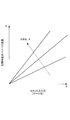
- FIG. 2 is a diagram showing the relationship between the dilution request compressor supply flow rate and the power generation request stack supply flow rate according to the load of the fuel cell stack.
- FIG. 3 shows a control block of the cathode system according to the present embodiment.
- FIG. 4 is a basic bypass flow rate calculation map when fully opened.
- FIG. 5 is a flow rate correction value calculation table.
- FIG. 6 is a time chart for explaining the operation of controlling the cathode system according to the present embodiment.
- FIG. 7 shows a control block of a cathode system according to a comparative example.
- an electrolyte membrane is sandwiched between an anode electrode (fuel electrode) and a cathode electrode (oxidant electrode), an anode gas containing hydrogen in the anode electrode (fuel gas), and a cathode gas containing oxygen in the cathode electrode (oxidant) Electricity is generated by supplying gas.
- the electrode reaction that proceeds in both the anode electrode and the cathode electrode is as follows.
- Anode electrode 2H 2 ⁇ 4H + + 4e ⁇ (1)
- Cathode electrode 4H + + 4e ⁇ + O 2 ⁇ 2H 2 O (2)
- the fuel cell generates an electromotive force of about 1 volt by the electrode reactions (1) and (2).
- a fuel cell When a fuel cell is used as a power source for automobiles, it requires a large amount of power, so it is used as a fuel cell stack in which several hundred fuel cells are stacked. Then, a fuel cell system that supplies anode gas and cathode gas to the fuel cell stack is configured, and electric power for driving the vehicle is taken out.
- FIG. 1 is a schematic diagram of a fuel cell system 100 according to an embodiment of the present invention.
- the fuel cell system 100 includes a fuel cell stack 1, a cathode gas supply / discharge device 2, an anode gas supply / discharge device 3, and a controller 4.
- the fuel cell stack 1 is formed by stacking several hundred fuel cells, and receives the supply of anode gas and cathode gas to generate electric power necessary for driving the vehicle.
- the cathode gas supply / discharge device 2 supplies the cathode gas to the fuel cell stack 1 and discharges the cathode off-gas discharged from the fuel cell stack 1 to the outside air.
- the cathode gas supply / discharge device 2 includes a cathode gas supply passage 20, a filter 21, a cathode compressor 22, a cathode gas discharge passage 23, a cathode pressure regulating valve 24, a bypass passage 25, a bypass valve 26, and a first flow rate.
- a sensor 27, a second flow rate sensor 28, a pressure sensor 29, and a temperature sensor 30 are provided.
- the cathode gas supply passage 20 is a passage through which the cathode gas supplied to the fuel cell stack 1 flows.
- the cathode gas supply passage 20 has one end connected to the filter 21 and the other end connected to the cathode gas inlet hole of the fuel cell stack 1.
- the filter 21 removes foreign matters in the cathode gas taken into the cathode gas supply passage 20.
- the cathode compressor 22 is provided in the cathode gas supply passage 20.
- the cathode compressor 22 takes air (outside air) as cathode gas into the cathode gas supply passage 20 via the filter 21 and supplies the air to the fuel cell stack 1.
- the cathode gas discharge passage 23 is a passage through which the cathode off gas discharged from the fuel cell stack 1 flows. One end of the cathode gas discharge passage 23 is connected to the cathode gas outlet hole of the fuel cell stack 1, and the other end is an open end.
- the cathode pressure regulating valve 24 is provided in the cathode gas discharge passage 23.
- the cathode pressure regulating valve 24 is controlled to be opened and closed by the controller 4 to adjust the pressure of the cathode gas supplied to the fuel cell stack 1 to a desired pressure.
- the bypass passage 25 is a passage provided so that a part of the cathode gas discharged from the cathode compressor 22 can be directly discharged to the cathode gas discharge passage 23 without going through the fuel cell stack 1 as necessary. It is.
- the bypass passage 25 has one end connected to the cathode gas supply passage 21 downstream from the cathode compressor 23 and the other end connected to the cathode gas discharge passage 24 downstream from the cathode pressure regulating valve 24.
- bypass valve 26 is provided in the bypass passage 25.
- the bypass valve 26 is controlled to be opened and closed by the controller 4 to adjust the flow rate of the cathode gas flowing through the bypass passage 25 (hereinafter referred to as “bypass flow rate”).
- the first flow rate sensor 27 is provided in the cathode gas supply passage 20 upstream of the cathode compressor 23.
- the first flow rate sensor 27 detects the flow rate of the cathode gas supplied to the compressor 23 (hereinafter referred to as “compressor supply flow rate”).
- the second flow rate sensor 28 is provided in the cathode gas supply passage 20 downstream of the connection portion with the bypass passage 26, that is, in the cathode supply passage 20 near the cathode gas inlet hole of the fuel cell stack 1.
- the second flow rate sensor 28 detects the flow rate of the cathode gas supplied to the fuel cell stack 1 (hereinafter referred to as “stack supply flow rate”).
- the pressure sensor 29 is provided in the cathode gas supply passage 20 downstream of the connection portion with the bypass passage 26, that is, in the cathode supply passage 20 near the cathode gas inlet hole of the fuel cell stack 1.
- the pressure sensor 29 detects the inlet pressure of the fuel cell stack (hereinafter referred to as “stack inlet pressure”).
- the temperature sensor 30 is provided in the cathode gas supply passage 20 near the discharge side of the cathode compressor 23.
- the temperature sensor 30 detects the temperature of the cathode gas discharged from the cathode compressor 23 (hereinafter referred to as “discharge temperature”).
- the anode gas supply / discharge device 3 supplies anode gas to the fuel cell stack 1 and discharges anode off-gas discharged from the fuel cell stack 1 to the cathode gas discharge passage 23.
- the anode gas supply / discharge device 3 includes a high-pressure tank 31, an anode gas supply passage 32, an anode pressure regulating valve 33, an anode gas discharge passage 34, and a purge valve 35.
- the high pressure tank 31 stores the anode gas supplied to the fuel cell stack 1 in a high pressure state.
- the anode gas supply passage 32 is a passage for supplying the anode gas discharged from the high-pressure tank 31 to the fuel cell stack 1.
- the anode gas supply passage 32 has one end connected to the high pressure tank 31 and the other end connected to the anode gas inlet hole of the fuel cell stack 1.
- the anode pressure regulating valve 33 is provided in the anode gas supply passage 32.
- the anode pressure regulating valve 34 is controlled to be opened and closed by the controller 4 to adjust the pressure of the anode gas supplied to the fuel cell stack 1 to a desired pressure.
- the anode gas discharge passage 34 is a passage through which the anode off gas discharged from the fuel cell stack 1 flows.
- the anode gas discharge passage 35 has one end connected to the anode gas outlet hole of the fuel cell stack 1 and the other end connected to the cathode gas discharge passage 23.
- the anode off-gas discharged to the cathode gas discharge passage 23 through the anode gas discharge passage 34 is mixed with the cathode off-gas and the cathode gas flowing through the bypass passage 26 in the cathode gas discharge passage 23 to be external to the fuel cell system 100.
- the anode off gas contains surplus anode gas (hydrogen) that has not been used in the electrode reaction, it is mixed with the cathode off gas and the cathode gas and discharged outside the fuel cell system 100 in this way.
- the hydrogen concentration in the exhaust gas is set to a predetermined concentration or less.
- the purge valve 35 is provided in the anode gas discharge passage 34.
- the purge valve 35 is controlled to be opened and closed by the controller 4 and controls the flow rate of the anode off gas discharged from the anode gas discharge passage 34 to the cathode gas discharge passage 23.
- the controller 4 includes a microcomputer having a central processing unit (CPU), a read only memory (ROM), a random access memory (RAM), and an input / output interface (I / O interface).
- CPU central processing unit
- ROM read only memory
- RAM random access memory
- I / O interface input / output interface
- the controller 4 receives signals from various sensors such as an atmospheric pressure sensor 41 that detects atmospheric pressure.
- the controller 4 requests the hydrogen concentration in the exhaust gas discharged to the outside of the fuel cell system 100 to be a predetermined concentration or less (hereinafter referred to as “dilution request”), a drive motor, and the like.
- the two requests namely, a request to generate electric power (hereinafter referred to as “required output power”) required by each electric component of the fuel cell system 100 (hereinafter referred to as “required output power”) by the fuel cell stack 1 (hereinafter referred to as “power generation request”) simultaneously.
- the cathode compressor 22 and the bypass valve 26 are feedback-controlled so as to satisfy.
- FIG. 2 shows a compressor supply flow rate (hereinafter referred to as “dilution-required compressor supply flow rate”) necessary for setting the hydrogen concentration of the exhaust gas discharged outside the fuel cell system 100 to a predetermined concentration or less, and the required output power.
- the power generation request stack supply flow rate is larger than the dilution request compressor supply.
- the cathode compressor 22 is feedback-controlled by simply using the target compressor supply flow rate as the power generation request stack supply flow rate, the flow rate of the cathode gas supplied to the fuel cell stack 1 becomes the power generation request stack supply flow rate.
- the stack 1 can generate the required generated power.
- the anode off gas flowing from the anode gas discharge passage 34 to the cathode gas discharge passage 23 can be diluted with the cathode off gas discharged from the fuel cell stack 1, so that the hydrogen concentration of the exhaust gas can be reduced to a predetermined concentration or less.
- the dilution request compressor supply flow rate is larger than the power generation request stack supply flow rate.
- the cathode compressor 22 is simply feedback controlled using the target compressor supply flow rate as the power generation request stack supply flow rate, the fuel cell stack 1 can generate the required generated power, but the cathode discharged from the fuel cell stack 1. Even if the anode off gas flowing from the anode gas discharge passage 34 to the cathode gas discharge passage 23 is diluted by the off gas, the hydrogen concentration of the exhaust gas cannot be reduced below a predetermined concentration.
- the cathode compressor 22 is feedback-controlled using the target compressor supply flow rate as the dilution request compressor supply flow rate, and the fuel cell stack 1 generates the required generated power. Therefore, the cathode compressor 22 must supply more cathode gas than the cathode gas flow rate (power generation required stack supply flow rate) necessary for this. Then, excess cathode gas unnecessary for power generation is supplied to the fuel cell stack 1, so that the electrolyte membrane of each fuel cell constituting the fuel cell stack 1 is dried and the power generation efficiency of the fuel cell stack 1 is reduced. There is a risk.
- the stack supply flow rate is set to the power generation request stack supply while the cathode compressor 22 is feedback controlled using the target compressor supply flow rate as the dilution request compressor supply flow rate.
- the bypass valve 26 needs to be feedback-controlled so that the flow rate becomes equal, and surplus cathode gas unnecessary for power generation needs to flow through the bypass passage 25. That is, it is necessary to open the bypass valve 26 so that the bypass flow rate becomes a flow rate obtained by subtracting the power generation request stack supply flow rate from the dilution request compressor supply flow rate (dilution request compressor supply flow rate-power generation request stack supply flow rate).
- FIG. 7 shows a cathode system control block according to a comparative example.
- the control block of the cathode system according to the comparative example includes a wet required stack supply flow rate calculation unit 101, a target stack supply flow rate setting unit 102, a stack required compressor supply flow rate calculation unit 103, a target compressor supply flow rate setting unit 104, and a cathode compressor.
- the control part 105, the target bypass valve opening degree calculation part 106, and the bypass valve control part 107 are provided.
- the wet demand stack supply flow rate calculation unit 101 receives the actual impedance of the fuel cell stack 1 calculated by the AC impedance method and a target impedance that is predetermined according to the load of the fuel cell stack 1.
- the wet demand stack supply flow rate calculation unit 101 sets the stack supply flow rate necessary for setting the actual impedance to the target impedance as the ultimate wet demand stack supply flow rate, and supplies the stack toward the set ultimate wet demand stack supply flow rate.
- a target value for changing the flow rate with a predetermined transient response is calculated as the wet demand stack supply flow rate.
- the ultimate required wet stack supply flow rate is, in other words, the required stack supply flow rate for controlling the wetness (water content) of the electrolyte membrane to the optimal wetness (required wetness) according to the load of the fuel cell stack 1. It is.
- the target stack supply flow rate setting unit 102 receives a power generation request stack supply flow rate and a wet request stack supply flow rate that are predetermined according to the load of the fuel cell stack 1.
- the target stack supply flow rate setting unit 102 sets the larger of the power generation request stack flow rate and the wet request stack supply flow rate as the target stack supply flow rate.
- the target stack supply flow rate setting unit 102 sets the optimum stack supply flow rate according to the load of the fuel cell stack 1 as the target stack supply flow rate.
- the stack required compressor supply flow rate calculation unit 103 receives the stack supply flow rate detected by the second flow rate sensor 28 (hereinafter referred to as “actual stack supply flow rate”) and the target stack supply flow rate.
- the stack required compressor supply flow rate calculation unit 103 calculates a target value of the compressor supply flow rate for changing the actual stack supply flow rate toward the target stack supply flow rate with a predetermined transient response as the stack required compressor supply flow rate.
- the target compressor supply flow rate setting unit 104 receives a dilution request compressor supply flow rate determined according to the load of the fuel cell stack 1 and a stack request compressor supply flow rate.
- the target compressor supply flow rate setting unit 104 sets the larger one of the dilution request compressor supply flow rate and the stack request compressor supply flow rate as the target compressor supply flow rate.
- the cathode compressor control unit 105 receives the compressor supply flow rate (hereinafter referred to as “actual compressor supply flow rate”) detected by the first flow rate sensor 27 and the target compressor supply flow rate.
- the cathode compressor control unit 105 controls the cathode compressor 22 so that the actual compressor supply flow rate becomes the target compressor supply flow rate.
- the actual stack supply flow rate and the target stack supply flow rate are input to the target bypass valve opening calculation unit 106.
- the target bypass valve opening calculation unit 106 calculates the target bypass valve opening based on the difference between the actual stack supply flow rate and the target stack supply flow rate (actual stack supply flow rate ⁇ target stack supply flow rate).
- the target bypass valve opening is an opening of the bypass valve 26 that is necessary for flowing the difference amount to the bypass passage 25 when the actual stack supply flow rate is larger than the target stack supply flow rate. Therefore, the target bypass valve opening increases as the difference amount increases, and becomes zero (fully closed) when the difference amount is zero or less.
- the actual opening of the bypass valve 26 and the target bypass valve opening are input to the bypass valve control unit 107.
- the bypass valve control unit 107 controls the opening degree of the bypass valve 26 to the target bypass valve opening degree.
- the stack required compressor supply flow rate calculation unit 103 wets the stack supply flow rate.
- the compressor supply flow rate required to obtain the required stack supply flow rate is calculated as the stack required compressor supply flow rate.
- the target compressor supply flow rate setting unit 104 selects the stack required compressor supply flow rate as the target compressor supply flow rate.
- the cathode compressor 22 is feedback-controlled so that the compressor supply flow rate becomes the stack required compressor supply flow rate.
- the bypass valve 26 is controlled to be fully closed by feedback control.
- the actual impedance is controlled to the target impedance.
- the target compressor supply flow rate setting unit 104 selects the dilution request compressor supply flow rate as the target compressor supply flow rate.
- the cathode compressor 22 is feedback-controlled so that the compressor supply flow rate becomes the dilution request compressor supply flow rate.
- the bypass valve 26 is gradually opened by feedback control so that the actual stack supply flow rate becomes the target stack supply flow rate.
- the bypass valve 26 is fully opened, the actual stack supply flow rate cannot be made the target stack supply flow rate, and the actual stack supply flow rate becomes larger than the target stack supply flow rate. If this state continues, the electrolyte membrane dries and the power generation efficiency of the fuel cell stack 1 decreases, so that the actual stack supply flow rate becomes the target stack supply flow rate, that is, the actual impedance becomes the target impedance. I want to reduce the compressor supply flow rate.
- the stack required compressor supply flow rate calculation unit 103 tries to control the stack required compressor supply flow rate in a decreasing direction.
- the target compressor supply flow rate setting unit 104 sets the larger one of the dilution request compressor supply flow rate and the stack request compressor supply flow rate as the target compressor supply flow rate. Therefore, if the stack demand compressor supply flow rate is controlled to decrease when the dilution request compressor supply flow rate is selected as the target compressor supply flow rate, the dilution request compressor supply flow rate will continue to be selected as the target compressor supply flow rate. End up.
- the cathode system control is configured to reduce the compressor supply flow rate so that the actual stack supply flow rate becomes the target stack supply flow rate.
- FIG. 3 shows a control block of the cathode system according to this embodiment.
- the same reference numerals are used for the same functions as those of the cathode control block according to the comparative example, and repeated description is appropriately omitted.
- the control block of the cathode system includes a wet request stack supply flow rate calculation unit 101, a target stack supply flow rate setting unit 102, a stack request compressor supply flow rate calculation unit 103, a cathode compressor control unit 105, and a target bypass valve opening calculation unit.
- the provisional target compressor supply flow rate setting unit 111 receives the dilution request compressor supply flow rate and the stack request compressor supply flow rate.
- the provisional target compressor supply flow rate setting unit 111 sets the larger one of the dilution request compressor supply flow rate and the stack request compressor supply flow rate as the provisional target compressor supply flow rate.
- the fully opened estimated bypass flow rate calculation unit 112 is an estimated value of the bypass flow rate (hereinafter, “fully opened estimated bypass flow rate” when the opening degree of the bypass valve 26 is assumed to be fully opened in the current operation state of the fuel cell system 100. Is calculated).
- the fully opened estimated bypass flow rate calculation unit 112 includes a fully opened basic bypass flow rate calculation unit 1121, a flow rate correction value calculation unit 1122, and a multiplication unit 1123.
- the full-open basic bypass flow rate calculation unit 1121 receives the stack inlet pressure and the atmospheric pressure.
- the fully open basic bypass flow rate calculation unit 1121 refers to the fully open basic bypass flow rate calculation map shown in FIG. 4 and calculates the fully open basic bypass flow rate based on the stack inlet pressure and the atmospheric pressure.
- the full-open basic bypass flow rate is such that the differential pressure across the bypass valve 26 increases as the stack inlet pressure (gauge pressure), that is, the pressure upstream of the bypass valve 26 increases. It grows because it grows. Further, if the stack inlet pressure (gauge pressure) is constant, the stack pressure increases as the atmospheric pressure increases.
- the discharge temperature is input to the flow rate correction value calculation unit 1122.
- the flow rate correction value calculation unit 1122 calculates a correction value based on the discharge temperature with reference to the flow rate correction value calculation table shown in FIG. As shown in the flow rate correction value calculation table of FIG. 5, the flow rate correction value decreases as the discharge temperature decreases.
- the multiplication unit 1123 receives the fully opened basic bypass flow rate and the flow rate correction value.
- the multiplier 1123 outputs the product of the fully opened basic bypass flow rate and the flow rate correction value as the fully opened estimated bypass flow rate.
- the compressor limit flow rate calculation unit 113 receives the wet request stack supply flow rate and the fully opened estimated bypass flow rate.
- the compressor limit flow rate calculation unit 113 calculates the compressor limit flow rate by adding the wet request stack supply flow rate and the fully opened estimated bypass flow rate.
- the target compressor supply flow rate setting unit 114 receives the temporary target compressor supply flow rate and the compressor limit flow rate.
- the target compressor supply flow rate setting unit 114 sets the smaller one of the temporary target compressor supply flow rate and the compressor limit flow rate as the target compressor supply flow rate.
- the target compressor supply flow rate setting unit 114 takes into consideration the operation state of the entire fuel cell system such as a dilution request, a power generation request, and a wetting request, and sets an optimal compressor supply flow rate according to the operating state of the fuel cell system. Set as the target compressor supply flow rate.
- the compressor supply flow rate is reduced so that the actual stack supply flow rate becomes the target stack supply flow rate when the bypass valve 26 is fully opened for the following reason. Can do.
- the stack request calculated by the stack request compressor supply flow rate calculation unit 103 is obtained.
- the compressor supply flow rate becomes smaller.
- the provisional target compressor supply flow rate setting unit 111 selects the dilution request compressor supply flow rate as the provisional target compressor supply flow rate.
- the wet request stack supply flow rate calculation unit 101 calculates a stack supply flow rate at which the actual impedance becomes the target impedance as the wet request stack supply flow rate. Therefore, the wet requested stack supply flow rate is smaller than the actual stack supply flow rate when the bypass valve 26 is fully opened.
- a sum of the wet request stack supply flow rate and the estimated bypass flow rate when fully opened is input to the target compressor supply flow rate setting unit 114 as a compressor limit flow rate.
- the compressor limit flow rate input to the target compressor supply flow rate setting unit 114 when the bypass valve 26 is fully opened is the sum of the wet request stack supply flow rate and the estimated bypass flow rate when fully opened.
- the dilution request compressor supply flow rate input to the target compressor supply flow rate setting unit 114 as the provisional target compressor supply flow rate is considered to be the sum of the actual stack supply flow rate (> wet request stack supply flow rate) and the fully opened estimated bypass flow rate. Can do.
- the compressor limit flow rate input to the target compressor supply flow rate setting unit 114 when the bypass valve 26 is fully opened is the dilution request compressor supply input to the target compressor supply flow rate setting unit 114 as the temporary target compressor supply flow rate. It becomes smaller than the flow rate.
- the target compressor supply flow rate setting unit 114 sets the compressor limit flow rate as the target compressor supply flow rate.
- the cathode compressor 22 is feedback-controlled so that the actual stack supply flow rate becomes the wet supply stack supply flow rate, so that the increased actual impedance becomes the target impedance. Can converge toward. Therefore, since it can suppress that the actual stack supply flow rate becomes larger than the target stack supply flow rate, it is possible to suppress the drying of the electrolyte membrane and suppress the power generation efficiency of the fuel cell stack 1 from decreasing.
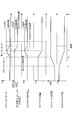
- FIG. 6 is a time chart for explaining the operation of controlling the cathode system according to the present embodiment.
- the control operation of the cathode system according to the comparative example is indicated by a thin solid line as necessary.
- the provisional target compressor supply flow rate setting unit 111 sets the dilution request compressor supply flow rate as the temporary target compressor supply flow rate, and the target compressor supply flow rate setting unit 114 sets the provisional target compressor supply flow rate as the target compressor supply flow rate. It is assumed that it is set.
- stack the pressure on the discharge side of the cathode compressor 22
- Inlet pressure the pressure on the discharge side of the cathode compressor 22
- the bypass valve 26 is gradually opened in conjunction with the decrease of the stack inlet pressure in order to maintain the bypass flow rate (FIGS. 6D and 6E).
- the bypass flow rate gradually decreases with the decrease of the stack inlet pressure (FIGS. 6D and 6E), and the actual stack supply flow rate is the target. It becomes larger than the stack supply flow rate (here, the wet request stack supply flow rate) (FIG. 6C). As a result, the actual impedance becomes larger than the target impedance (FIG. 6A).
- the stack required compressor supply flow rate calculation unit 103 tries to control the stack required compressor supply flow rate so that the actual stack supply flow rate becomes the target stack supply flow rate. To do.
- the target compressor supply flow rate setting unit 104 selects the larger one of the dilution request compressor supply flow rate and the stack request compressor supply flow rate as the target compressor supply flow rate. Therefore, when the stack required compressor supply flow rate decreases, the target compressor supply flow rate setting unit 104 continues to select the dilution request compressor supply flow rate as the target compressor supply flow rate (FIG. 6B).
- the compressor supply flow rate remains the dilution request compressor supply flow rate.
- the stack supply flow rate cannot be the target stack supply flow rate, and the actual impedance continues to be larger than the target impedance.
- the target compressor supply flow rate setting unit 114 sets the compressor limit flow rate as the target compressor supply flow rate (time t3, FIG. 6). (B)).
- the compressor limit flow rate is the sum of the wet requested stack supply flow rate and the estimated bypass flow rate when fully open, so the actual stack supply flow rate can be controlled to the wet required stack supply flow rate, and the actual impedance can be controlled to the target impedance. Yes (FIG. 6A). As a result, the drying of the electrolyte membrane can be suppressed, and the power generation efficiency of the fuel cell stack 1 can be suppressed from decreasing.
- the purge valve 35 is closed. By controlling, it is only necessary to prevent the hydrogen concentration of the exhaust gas from exceeding a predetermined concentration.
- one of the power generation request stack supply flow rate and the wet request stack supply flow rate is calculated as the target stack supply flow rate according to the load of the fuel cell stack, and the stack supply flow rate is equal to the target stack supply flow rate.
- the bypass valve 26 is feedback-controlled.
- one of the stack required compressor supply flow rate and the dilution required stack supply flow rate is calculated as the provisional target compressor supply flow rate according to the operating state of the fuel cell system. If the bypass valve 26 is fully opened when the dilution request stack supply flow rate is selected as the temporary target compressor supply flow rate, the cathode compressor 22 uses a flow rate smaller than the temporary target compressor supply flow rate as the target compressor supply flow rate. It was decided to perform feedback control. Specifically, the sum of the estimated bypass flow rate when fully opened and the wet requested stack supply flow rate are used as the compressor limit flow rate, and the smaller of the provisional target compressor supply flow rate and the compressor limit flow rate is set as the target compressor supply flow rate. It was decided to perform feedback control.
- the cathode compressor 22 and the bypass valve 26 can be feedback-controlled so that the actual stack supply flow rate becomes the target stack supply flow rate while satisfying the dilution request.
- the cathode compressor 22 can be feedback controlled so that the actual stack supply flow rate becomes the wet supply stack supply flow rate. it can. Therefore, since it can suppress that the actual stack supply flow rate becomes larger than the target stack supply flow rate, it is possible to suppress the drying of the electrolyte membrane and suppress the power generation efficiency of the fuel cell stack 1 from decreasing.
- the bypass valve even when the bypass valve reaches a predetermined opening degree (for example, fully open) for some reason, it is possible to prevent the cathode gas unnecessary for power generation from being supplied to the fuel cell. Therefore, drying of the electrolyte membrane can be suppressed.
- a predetermined opening degree for example, fully open
- the power generation request stack supply flow rate and the wet request stack supply flow rate are input to the target stack supply flow rate calculation unit 102.
- these stack supply flow rates may be input, and these maximum values may be set as the target stack supply flow rate.
- the dilution request compressor supply flow rate and the stack request compressor supply flow rate are input to the provisional target compressor supply flow rate calculation unit 111.
- compressor supply for preventing surging of the cathode compressor 22 is provided.
- the flow rate may be input, and these maximum values may be used as the provisional target compressor supply flow rate.
Landscapes
- Life Sciences & Earth Sciences (AREA)
- Engineering & Computer Science (AREA)
- Manufacturing & Machinery (AREA)
- Sustainable Development (AREA)
- Sustainable Energy (AREA)
- Chemical & Material Sciences (AREA)
- Chemical Kinetics & Catalysis (AREA)
- Electrochemistry (AREA)
- General Chemical & Material Sciences (AREA)
- Fuel Cell (AREA)
Abstract
Description
カソード電極 : 4H+ +4e- +O2 →2H2O …(2)
Claims (6)
- アノードガス及びカソードガスを燃料電池スタックに供給して発電する燃料電池システムであって、
カソードガスを供給するコンプレッサと、
前記コンプレッサから吐出されたカソードガスの一部を、前記燃料電池スタックをバイパスさせてカソードガス排出通路に排出するバイパス通路と、
前記バイパス通路に設けられ、前記バイパス通路を流れるカソードガスの流量を調節するバイパス弁と、
前記燃料電池スタックの要求に応じて、前記燃料電池スタックに供給するカソードガス流量の目標値を算出する目標燃料電池供給流量算出部と、
前記燃料電池システムの運転状態に応じて、前記コンプレッサが供給するカソードガス流量を制御するコンプレッサ供給流量制御部と、
目標燃料電池供給流量に基づいて、前記コンプレッサから燃料電池スタックに供給されるカソードガスの流量が、前記目標燃料電池供給流量となるように、バイパス弁を制御するバイパス弁制御部と、
前記バイパス弁が所定開度であって、燃料電池スタックへ供給されるカソードガス流量が前記目標燃料電池供給流量以上のときに、前記コンプレッサが供給するカソードガス流量を制限するコンプレッサ供給流量制限部と、
を備える燃料電池システム。 - 前記コンプレッサ供給流量制限部は、
前記バイパス弁の全開時に前記バイパス通路へ供給できるバイパス可能流量に基づいて、前記コンプレッサが供給するカソードガス流量を制限する、
請求項1に記載の燃料電池システム。 - 前記燃料電池スタックの電解質膜の湿潤度を要求湿潤度にするために、前記要求湿潤度と実湿潤度とに基づいて前記燃料電池スタックに供給する必要のあるカソードガス流量を算出する湿潤要求燃料電池供給流量算出部と、
前記燃料電池スタックの発電要求に基づいて、前記燃料電池スタックに供給するカソードガス流量を算出する発電要求燃料電池供給流量算出部と、
を備え、
前記目標燃料電池供給流量算出部は、
湿潤要求燃料電池供給流量、及び、発電要求燃料電池供給流量の大きいほうを、前記燃料電池スタックに供給すべきカソードガス流量の目標値とする、
請求項1又は請求項2に記載の燃料電池システム。 - 前記コンプレッサ供給流量制御部は、
前記燃料電池システムの運転状態に応じて、前記コンプレッサが供給するカソードガス流量の暫定目標値を算出する暫定目標コンプレッサ供給流量算出部を備え、
前記コンプレッサ供給流量制限部は、
前記湿潤要求燃料電池供給流量と前記バイパス可能流量との加算値をコンプレッサ制限流量として算出し、暫定目標コンプレッサ供給流量、及び、前記コンプレッサ制限流量の小さいほうを選択することで、前記コンプレッサが供給するカソードガス流量を制限する、
請求項3に記載の燃料電池システム。 - 前記コンプレッサ供給流量制御部は、
前記燃料電池システムから外気に排出する排出ガスに応じて、その排出ガスの水素濃度を所定濃度以下に希釈するためのカソードガス流量を希釈要求コンプレッサ供給流量として算出する希釈要求コンプレッサ供給流量算出部を備え、
前記目標燃料電池供給流量、及び、前記希釈要求コンプレッサ供給流量の大きい値に基づいてコンプレッサ供給流量を制御する、
請求項1から請求項4までのいずれか1つに記載の燃料電池システム。 - 前記バイパス可能流量は、
前記バイパス弁の前後差圧に基づいて算出される、
請求項1から請求項5までのいずれか1つに記載の燃料電池システム。
Priority Applications (5)
| Application Number | Priority Date | Filing Date | Title |
|---|---|---|---|
| JP2014521438A JP5796680B2 (ja) | 2012-06-15 | 2013-06-14 | 燃料電池システム |
| CA2876576A CA2876576C (en) | 2012-06-15 | 2013-06-14 | A fuel cell system with oxidant flow rate control |
| US14/407,272 US10581096B2 (en) | 2012-06-15 | 2013-06-14 | Fuel cell system |
| CN201380031574.9A CN104380510B (zh) | 2012-06-15 | 2013-06-14 | 燃料电池系统 |
| EP13805021.6A EP2863463B1 (en) | 2012-06-15 | 2013-06-14 | Fuel cell system |
Applications Claiming Priority (2)
| Application Number | Priority Date | Filing Date | Title |
|---|---|---|---|
| JP2012-135721 | 2012-06-15 | ||
| JP2012135721 | 2012-06-15 |
Publications (1)
| Publication Number | Publication Date |
|---|---|
| WO2013187514A1 true WO2013187514A1 (ja) | 2013-12-19 |
Family
ID=49758332
Family Applications (1)
| Application Number | Title | Priority Date | Filing Date |
|---|---|---|---|
| PCT/JP2013/066505 WO2013187514A1 (ja) | 2012-06-15 | 2013-06-14 | 燃料電池システム |
Country Status (6)
| Country | Link |
|---|---|
| US (1) | US10581096B2 (ja) |
| EP (1) | EP2863463B1 (ja) |
| JP (1) | JP5796680B2 (ja) |
| CN (1) | CN104380510B (ja) |
| CA (1) | CA2876576C (ja) |
| WO (1) | WO2013187514A1 (ja) |
Cited By (5)
| Publication number | Priority date | Publication date | Assignee | Title |
|---|---|---|---|---|
| JP2016012480A (ja) * | 2014-06-30 | 2016-01-21 | 本田技研工業株式会社 | 燃料電池システム及び燃料電池車両 |
| EP3018745A1 (en) * | 2014-11-05 | 2016-05-11 | Toyota Jidosha Kabushiki Kaisha | Fuel cell system |
| EP3185344A4 (en) * | 2014-08-20 | 2017-09-20 | Nissan Motor Co., Ltd | Fuel cell system and fuel cell system control method |
| WO2017158957A1 (ja) * | 2016-03-15 | 2017-09-21 | 日産自動車株式会社 | 燃料電池システムの湿潤状態制御方法及び湿潤状態制御装置 |
| JP7434399B2 (ja) | 2022-03-31 | 2024-02-20 | 本田技研工業株式会社 | 燃料電池システム |
Families Citing this family (7)
| Publication number | Priority date | Publication date | Assignee | Title |
|---|---|---|---|---|
| WO2014103547A1 (ja) * | 2012-12-28 | 2014-07-03 | 日産自動車株式会社 | 燃料電池システム |
| JP2016009518A (ja) * | 2014-06-20 | 2016-01-18 | 本田技研工業株式会社 | 燃料電池システムの運転方法 |
| US10069157B2 (en) * | 2015-05-18 | 2018-09-04 | Hyundai Motor Company | Fuel cell system having valve module between fuel cell stack and humidifier |
| JP6330832B2 (ja) * | 2016-03-04 | 2018-05-30 | トヨタ自動車株式会社 | 燃料電池システム及びその制御方法 |
| DE102018212420A1 (de) * | 2018-07-25 | 2020-01-30 | Bayerische Motoren Werke Aktiengesellschaft | Die Erfindung betrifft ein Brennstoffzellensystem für ein Kraftfahrzeug |
| US10862143B2 (en) * | 2019-01-30 | 2020-12-08 | Toyota Jidosha Kabushiki Kaisha | Turbo compressor path and rate control |
| CN113782789B (zh) * | 2021-08-31 | 2022-03-18 | 金华氢途科技有限公司 | 一种燃料电池系统阳极压力保护方法 |
Citations (7)
| Publication number | Priority date | Publication date | Assignee | Title |
|---|---|---|---|---|
| JP2003208911A (ja) * | 2002-01-11 | 2003-07-25 | Nissan Motor Co Ltd | 燃料電池システム |
| JP2006164626A (ja) * | 2004-12-03 | 2006-06-22 | Nissan Motor Co Ltd | 燃料電池システム |
| JP2007257956A (ja) * | 2006-03-22 | 2007-10-04 | Nissan Motor Co Ltd | 燃料電池システム |
| JP2009123550A (ja) | 2007-11-15 | 2009-06-04 | Toyota Motor Corp | 燃料電池システム |
| JP2011222176A (ja) * | 2010-04-06 | 2011-11-04 | Honda Motor Co Ltd | 燃料電池システム |
| WO2011148426A1 (ja) * | 2010-05-27 | 2011-12-01 | トヨタ自動車株式会社 | 燃料電池システム |
| JP2012109182A (ja) * | 2010-11-19 | 2012-06-07 | Nissan Motor Co Ltd | 燃料電池システム |
Family Cites Families (5)
| Publication number | Priority date | Publication date | Assignee | Title |
|---|---|---|---|---|
| JP4498845B2 (ja) * | 2004-07-16 | 2010-07-07 | 本田技研工業株式会社 | 燃料電池の排出ガス処理装置 |
| JP5044969B2 (ja) * | 2006-04-07 | 2012-10-10 | トヨタ自動車株式会社 | 燃料電池運転システム及び燃料電池運転システムにおける弁の凍結防止方法 |
| JP2008016399A (ja) | 2006-07-10 | 2008-01-24 | Toyota Motor Corp | 燃料電池システム |
| JP5375077B2 (ja) | 2008-12-24 | 2013-12-25 | トヨタ自動車株式会社 | 燃料電池システムおよび燃料電池システムの制御方法 |
| KR101300897B1 (ko) * | 2009-07-30 | 2013-08-27 | 도요타지도샤가부시키가이샤 | 연료 전지 시스템 |
-
2013
- 2013-06-14 US US14/407,272 patent/US10581096B2/en not_active Expired - Fee Related
- 2013-06-14 JP JP2014521438A patent/JP5796680B2/ja not_active Expired - Fee Related
- 2013-06-14 EP EP13805021.6A patent/EP2863463B1/en active Active
- 2013-06-14 CA CA2876576A patent/CA2876576C/en active Active
- 2013-06-14 WO PCT/JP2013/066505 patent/WO2013187514A1/ja active Application Filing
- 2013-06-14 CN CN201380031574.9A patent/CN104380510B/zh active Active
Patent Citations (7)
| Publication number | Priority date | Publication date | Assignee | Title |
|---|---|---|---|---|
| JP2003208911A (ja) * | 2002-01-11 | 2003-07-25 | Nissan Motor Co Ltd | 燃料電池システム |
| JP2006164626A (ja) * | 2004-12-03 | 2006-06-22 | Nissan Motor Co Ltd | 燃料電池システム |
| JP2007257956A (ja) * | 2006-03-22 | 2007-10-04 | Nissan Motor Co Ltd | 燃料電池システム |
| JP2009123550A (ja) | 2007-11-15 | 2009-06-04 | Toyota Motor Corp | 燃料電池システム |
| JP2011222176A (ja) * | 2010-04-06 | 2011-11-04 | Honda Motor Co Ltd | 燃料電池システム |
| WO2011148426A1 (ja) * | 2010-05-27 | 2011-12-01 | トヨタ自動車株式会社 | 燃料電池システム |
| JP2012109182A (ja) * | 2010-11-19 | 2012-06-07 | Nissan Motor Co Ltd | 燃料電池システム |
Cited By (8)
| Publication number | Priority date | Publication date | Assignee | Title |
|---|---|---|---|---|
| JP2016012480A (ja) * | 2014-06-30 | 2016-01-21 | 本田技研工業株式会社 | 燃料電池システム及び燃料電池車両 |
| EP3185344A4 (en) * | 2014-08-20 | 2017-09-20 | Nissan Motor Co., Ltd | Fuel cell system and fuel cell system control method |
| US10141587B2 (en) | 2014-08-20 | 2018-11-27 | Nissan Motor Co., Ltd. | Fuel cell system with cathode bypass valve and control method for fuel cell system |
| EP3018745A1 (en) * | 2014-11-05 | 2016-05-11 | Toyota Jidosha Kabushiki Kaisha | Fuel cell system |
| CN105591128A (zh) * | 2014-11-05 | 2016-05-18 | 丰田自动车株式会社 | 燃料电池系统 |
| WO2017158957A1 (ja) * | 2016-03-15 | 2017-09-21 | 日産自動車株式会社 | 燃料電池システムの湿潤状態制御方法及び湿潤状態制御装置 |
| US10305127B2 (en) | 2016-03-15 | 2019-05-28 | Nissan Motor Co., Ltd. | Wet state control method for fuel cell system and wet state control device for the same |
| JP7434399B2 (ja) | 2022-03-31 | 2024-02-20 | 本田技研工業株式会社 | 燃料電池システム |
Also Published As
| Publication number | Publication date |
|---|---|
| JPWO2013187514A1 (ja) | 2016-02-08 |
| CA2876576C (en) | 2019-05-14 |
| CA2876576A1 (en) | 2013-12-19 |
| CN104380510A (zh) | 2015-02-25 |
| US10581096B2 (en) | 2020-03-03 |
| US20150162629A1 (en) | 2015-06-11 |
| EP2863463B1 (en) | 2020-08-05 |
| EP2863463A1 (en) | 2015-04-22 |
| JP5796680B2 (ja) | 2015-10-21 |
| EP2863463A4 (en) | 2015-07-29 |
| CN104380510B (zh) | 2016-12-28 |
Similar Documents
| Publication | Publication Date | Title |
|---|---|---|
| JP5796680B2 (ja) | 燃料電池システム | |
| JP5858139B2 (ja) | 燃料電池システム | |
| JP6065117B2 (ja) | 燃料電池システム及び燃料電池システムの制御方法 | |
| JP5522309B2 (ja) | 燃料電池システム | |
| JP6137315B2 (ja) | 燃料電池システム及び燃料電池システムの制御方法 | |
| JP5812118B2 (ja) | 燃料電池システム | |
| JP6079788B2 (ja) | 燃料電池システム | |
| EP2717371B1 (en) | Fuel cell system | |
| JP5983862B2 (ja) | 燃料電池システム及び燃料電池システムの制御方法 | |
| JP6064623B2 (ja) | 燃料電池システム | |
| JP6136185B2 (ja) | 燃料電池システム | |
| JP6287010B2 (ja) | 燃料電池システム | |
| JP6064622B2 (ja) | 燃料電池システム | |
| JP4675605B2 (ja) | 燃料電池の酸化剤供給装置 |
Legal Events
| Date | Code | Title | Description |
|---|---|---|---|
| 121 | Ep: the epo has been informed by wipo that ep was designated in this application |
Ref document number: 13805021 Country of ref document: EP Kind code of ref document: A1 |
|
| ENP | Entry into the national phase |
Ref document number: 2014521438 Country of ref document: JP Kind code of ref document: A |
|
| WWE | Wipo information: entry into national phase |
Ref document number: 14407272 Country of ref document: US |
|
| ENP | Entry into the national phase |
Ref document number: 2876576 Country of ref document: CA |
|
| NENP | Non-entry into the national phase |
Ref country code: DE |