WO2017158957A1 - 燃料電池システムの湿潤状態制御方法及び湿潤状態制御装置 - Google Patents
燃料電池システムの湿潤状態制御方法及び湿潤状態制御装置 Download PDFInfo
- Publication number
- WO2017158957A1 WO2017158957A1 PCT/JP2016/086636 JP2016086636W WO2017158957A1 WO 2017158957 A1 WO2017158957 A1 WO 2017158957A1 JP 2016086636 W JP2016086636 W JP 2016086636W WO 2017158957 A1 WO2017158957 A1 WO 2017158957A1
- Authority
- WO
- WIPO (PCT)
- Prior art keywords
- flow rate
- cathode gas
- fuel cell
- pressure
- wet
- Prior art date
Links
Images


Classifications
-
- H—ELECTRICITY
- H01—ELECTRIC ELEMENTS
- H01M—PROCESSES OR MEANS, e.g. BATTERIES, FOR THE DIRECT CONVERSION OF CHEMICAL ENERGY INTO ELECTRICAL ENERGY
- H01M8/00—Fuel cells; Manufacture thereof
- H01M8/04—Auxiliary arrangements, e.g. for control of pressure or for circulation of fluids
- H01M8/04298—Processes for controlling fuel cells or fuel cell systems
- H01M8/04694—Processes for controlling fuel cells or fuel cell systems characterised by variables to be controlled
- H01M8/04746—Pressure; Flow
- H01M8/04776—Pressure; Flow at auxiliary devices, e.g. reformer, compressor, burner
-
- H—ELECTRICITY
- H01—ELECTRIC ELEMENTS
- H01M—PROCESSES OR MEANS, e.g. BATTERIES, FOR THE DIRECT CONVERSION OF CHEMICAL ENERGY INTO ELECTRICAL ENERGY
- H01M8/00—Fuel cells; Manufacture thereof
- H01M8/04—Auxiliary arrangements, e.g. for control of pressure or for circulation of fluids
- H01M8/04082—Arrangements for control of reactant parameters, e.g. pressure or concentration
- H01M8/04089—Arrangements for control of reactant parameters, e.g. pressure or concentration of gaseous reactants
- H01M8/04119—Arrangements for control of reactant parameters, e.g. pressure or concentration of gaseous reactants with simultaneous supply or evacuation of electrolyte; Humidifying or dehumidifying
- H01M8/04126—Humidifying
-
- H—ELECTRICITY
- H01—ELECTRIC ELEMENTS
- H01M—PROCESSES OR MEANS, e.g. BATTERIES, FOR THE DIRECT CONVERSION OF CHEMICAL ENERGY INTO ELECTRICAL ENERGY
- H01M8/00—Fuel cells; Manufacture thereof
- H01M8/04—Auxiliary arrangements, e.g. for control of pressure or for circulation of fluids
- H01M8/04298—Processes for controlling fuel cells or fuel cell systems
- H01M8/04313—Processes for controlling fuel cells or fuel cell systems characterised by the detection or assessment of variables; characterised by the detection or assessment of failure or abnormal function
- H01M8/0438—Pressure; Ambient pressure; Flow
- H01M8/04395—Pressure; Ambient pressure; Flow of cathode reactants at the inlet or inside the fuel cell
-
- H—ELECTRICITY
- H01—ELECTRIC ELEMENTS
- H01M—PROCESSES OR MEANS, e.g. BATTERIES, FOR THE DIRECT CONVERSION OF CHEMICAL ENERGY INTO ELECTRICAL ENERGY
- H01M8/00—Fuel cells; Manufacture thereof
- H01M8/04—Auxiliary arrangements, e.g. for control of pressure or for circulation of fluids
- H01M8/04298—Processes for controlling fuel cells or fuel cell systems
- H01M8/04313—Processes for controlling fuel cells or fuel cell systems characterised by the detection or assessment of variables; characterised by the detection or assessment of failure or abnormal function
- H01M8/04492—Humidity; Ambient humidity; Water content
-
- H—ELECTRICITY
- H01—ELECTRIC ELEMENTS
- H01M—PROCESSES OR MEANS, e.g. BATTERIES, FOR THE DIRECT CONVERSION OF CHEMICAL ENERGY INTO ELECTRICAL ENERGY
- H01M8/00—Fuel cells; Manufacture thereof
- H01M8/04—Auxiliary arrangements, e.g. for control of pressure or for circulation of fluids
- H01M8/04298—Processes for controlling fuel cells or fuel cell systems
- H01M8/04694—Processes for controlling fuel cells or fuel cell systems characterised by variables to be controlled
- H01M8/04701—Temperature
- H01M8/04738—Temperature of auxiliary devices, e.g. reformer, compressor, burner
-
- H—ELECTRICITY
- H01—ELECTRIC ELEMENTS
- H01M—PROCESSES OR MEANS, e.g. BATTERIES, FOR THE DIRECT CONVERSION OF CHEMICAL ENERGY INTO ELECTRICAL ENERGY
- H01M8/00—Fuel cells; Manufacture thereof
- H01M8/04—Auxiliary arrangements, e.g. for control of pressure or for circulation of fluids
- H01M8/04298—Processes for controlling fuel cells or fuel cell systems
- H01M8/04694—Processes for controlling fuel cells or fuel cell systems characterised by variables to be controlled
- H01M8/04746—Pressure; Flow
- H01M8/04753—Pressure; Flow of fuel cell reactants
-
- H—ELECTRICITY
- H01—ELECTRIC ELEMENTS
- H01M—PROCESSES OR MEANS, e.g. BATTERIES, FOR THE DIRECT CONVERSION OF CHEMICAL ENERGY INTO ELECTRICAL ENERGY
- H01M8/00—Fuel cells; Manufacture thereof
- H01M8/04—Auxiliary arrangements, e.g. for control of pressure or for circulation of fluids
- H01M8/04298—Processes for controlling fuel cells or fuel cell systems
- H01M8/04694—Processes for controlling fuel cells or fuel cell systems characterised by variables to be controlled
- H01M8/04746—Pressure; Flow
- H01M8/04761—Pressure; Flow of fuel cell exhausts
-
- H—ELECTRICITY
- H01—ELECTRIC ELEMENTS
- H01M—PROCESSES OR MEANS, e.g. BATTERIES, FOR THE DIRECT CONVERSION OF CHEMICAL ENERGY INTO ELECTRICAL ENERGY
- H01M8/00—Fuel cells; Manufacture thereof
- H01M8/04—Auxiliary arrangements, e.g. for control of pressure or for circulation of fluids
- H01M8/04298—Processes for controlling fuel cells or fuel cell systems
- H01M8/04694—Processes for controlling fuel cells or fuel cell systems characterised by variables to be controlled
- H01M8/04746—Pressure; Flow
- H01M8/04768—Pressure; Flow of the coolant
-
- H—ELECTRICITY
- H01—ELECTRIC ELEMENTS
- H01M—PROCESSES OR MEANS, e.g. BATTERIES, FOR THE DIRECT CONVERSION OF CHEMICAL ENERGY INTO ELECTRICAL ENERGY
- H01M8/00—Fuel cells; Manufacture thereof
- H01M8/04—Auxiliary arrangements, e.g. for control of pressure or for circulation of fluids
- H01M8/04298—Processes for controlling fuel cells or fuel cell systems
- H01M8/04694—Processes for controlling fuel cells or fuel cell systems characterised by variables to be controlled
- H01M8/04746—Pressure; Flow
- H01M8/04783—Pressure differences, e.g. between anode and cathode
-
- H—ELECTRICITY
- H01—ELECTRIC ELEMENTS
- H01M—PROCESSES OR MEANS, e.g. BATTERIES, FOR THE DIRECT CONVERSION OF CHEMICAL ENERGY INTO ELECTRICAL ENERGY
- H01M8/00—Fuel cells; Manufacture thereof
- H01M8/04—Auxiliary arrangements, e.g. for control of pressure or for circulation of fluids
- H01M8/04298—Processes for controlling fuel cells or fuel cell systems
- H01M8/04694—Processes for controlling fuel cells or fuel cell systems characterised by variables to be controlled
- H01M8/04828—Humidity; Water content
- H01M8/04835—Humidity; Water content of fuel cell reactants
-
- H—ELECTRICITY
- H01—ELECTRIC ELEMENTS
- H01M—PROCESSES OR MEANS, e.g. BATTERIES, FOR THE DIRECT CONVERSION OF CHEMICAL ENERGY INTO ELECTRICAL ENERGY
- H01M8/00—Fuel cells; Manufacture thereof
- H01M8/04—Auxiliary arrangements, e.g. for control of pressure or for circulation of fluids
- H01M8/04298—Processes for controlling fuel cells or fuel cell systems
- H01M8/04992—Processes for controlling fuel cells or fuel cell systems characterised by the implementation of mathematical or computational algorithms, e.g. feedback control loops, fuzzy logic, neural networks or artificial intelligence
-
- Y—GENERAL TAGGING OF NEW TECHNOLOGICAL DEVELOPMENTS; GENERAL TAGGING OF CROSS-SECTIONAL TECHNOLOGIES SPANNING OVER SEVERAL SECTIONS OF THE IPC; TECHNICAL SUBJECTS COVERED BY FORMER USPC CROSS-REFERENCE ART COLLECTIONS [XRACs] AND DIGESTS
- Y02—TECHNOLOGIES OR APPLICATIONS FOR MITIGATION OR ADAPTATION AGAINST CLIMATE CHANGE
- Y02E—REDUCTION OF GREENHOUSE GAS [GHG] EMISSIONS, RELATED TO ENERGY GENERATION, TRANSMISSION OR DISTRIBUTION
- Y02E60/00—Enabling technologies; Technologies with a potential or indirect contribution to GHG emissions mitigation
- Y02E60/30—Hydrogen technology
- Y02E60/50—Fuel cells
Definitions
- the present invention relates to a wet state control method and a wet state control device for a fuel cell system.
- a fuel cell system is known in which a part of cathode gas supplied from a compressor to a cathode system is passed through a bypass passage so as to bypass the fuel cell.
- JP 2010-114039A discloses an example of such a fuel cell system.
- the pressure and flow rate of the cathode system are different from various viewpoints such as dilution of anode offgas and avoidance of turbosurge. It may vary differently from the load requirement. As a result, the flow rate of the cathode gas supplied to the fuel cell is not properly maintained, and the wet state of the fuel cell may not be suitably maintained.
- the present invention has been made paying attention to such problems, and it is an object of the present invention to provide a wet state control method and a wet state control apparatus for a fuel cell system that can more suitably control the wet state of the fuel cell.
- the wet control parameters including the bypass valve opening, the cathode gas pressure, and the cathode gas flow rate are adjusted.
- a wet state control method of a fuel cell system for controlling a wet state of a fuel cell is provided.
- this wet state control method when the fuel cell is controlled in the wet direction, at least one of the cathode gas flow rate and the cathode gas pressure is adjusted in preference to the adjustment of the bypass valve opening.
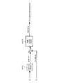
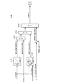
- FIG. 1 is a diagram showing a configuration of a fuel cell system according to an embodiment of the present invention.
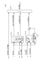
- FIG. 2 is a block diagram for explaining the overall function of the controller relating to the wetting control.
- FIG. 3 is a diagram for explaining the details of the control by the film wetting F / B control unit.
- FIG. 4 is a diagram for explaining a calculation mode of the target water balance.
- FIG. 5 is a diagram for explaining logic for setting priorities of the respective wet control parameters during the wet operation.
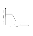
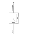
- FIG. 6 is a diagram showing a film wetting control map.
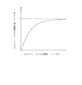
- FIG. 7 is a map showing the relationship between the bypass opening and the bypass flow rate ratio.
- FIG. 8 is a diagram illustrating the function of the target pressure calculation unit.
- FIG. 1 is a diagram showing a configuration of a fuel cell system according to an embodiment of the present invention.
- FIG. 2 is a block diagram for explaining the overall function of the controller relating to the wetting control.
- FIG. 3 is a diagram for
- FIG. 9 is a block diagram illustrating a calculation mode of the target pressure.
- FIG. 10 is a diagram illustrating the function of the target flow rate calculation unit.
- FIG. 11 is a block diagram for explaining how to calculate the target flow rate.
- FIG. 12 is a diagram illustrating the function of the air flow rate / pressure F / B control unit.
- FIG. 13 is a block diagram for explaining the control of the anode system.
- FIG. 14 shows an example of the target HRB rotation speed map.
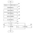
- FIG. 15 is a flowchart illustrating the wet control of the fuel cell system.
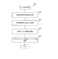
- FIG. 16 is a flowchart for explaining the flow of the wet operation.
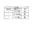
- FIG. 17 is a table showing the relationship between the priority order of each wet control parameter and the increasing / decreasing tendency of these wet control parameters during the wet operation.
- FIG. 18 is a diagram illustrating an example of a change in the state of the fuel cell system during a wet operation at a certain required load.
- FIG. 19 is a flowchart for explaining the flow of the dry operation.
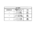
- FIG. 20 is a table showing the relationship between the priority order of each wetness control parameter during the dry operation and the increasing / decreasing tendency of these wetness control parameters.
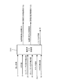
- FIG. 21 is a time chart for explaining the flow over time in the wet control of the fuel cell system.
- FIG. 1 is a configuration diagram illustrating an example of a configuration of a fuel cell system 100 according to an embodiment of the present invention.
- a fuel cell system 100 shown in the figure supplies anode gas (fuel) and cathode gas (air) necessary for power generation from the outside to a fuel cell stack 1 as a fuel cell, and the fuel cell is configured according to an electric load. Configure the power supply system to generate power.
- the fuel cell system 100 includes a fuel cell stack 1, a cathode gas supply / discharge device 2, an anode gas supply / discharge device 3, a stack cooling device 4, a load device 5, an impedance measurement device 6, and a controller 200. .
- the fuel cell stack 1 is a stacked battery in which a plurality of fuel cells are stacked as described above.
- the fuel cell stack 1 is connected to the load device 5 and supplies power to the load device 5.
- the fuel cell stack 1 generates a DC voltage of, for example, several hundred V (volts).
- the fuel cell constituting the fuel cell stack 1 is mainly composed of an electrolyte membrane, an anode electrode, and a cathode electrode.
- the electrolyte membrane exhibits good electrical conductivity with an appropriate degree of wetness (water content).
- the wet state of the electrolyte membrane in each fuel cell is referred to as “the wet state of the fuel cell stack 1”, “the wet state of the fuel cell”, or simply “the wet state”.
- the cathode gas supply / discharge device 2 is a device that supplies cathode gas to the fuel cell stack 1 and discharges cathode off-gas discharged from the fuel cell stack 1 to the atmosphere.
- the cathode gas supply / discharge device 2 includes a cathode gas supply passage 21, a compressor 22, an air flow meter 23, an intercooler 24, a cathode pressure sensor 25, a cathode gas discharge passage 26, a cathode pressure regulating valve 27, and a bypass passage 28. And a bypass valve 29.
- the cathode gas supply passage 21 is a passage for supplying cathode gas to the fuel cell stack 1. One end of the cathode gas supply passage 21 is open, and the other end is connected to the cathode gas inlet hole of the fuel cell stack 1.
- the compressor 22 supplies air containing oxygen to the cathode system including the cathode gas supply passage 21, the fuel cell stack 1, the bypass passage 28, and the cathode gas discharge passage 26.
- the compressor 22 is provided at the open end of one end of the cathode gas supply passage 21.
- the compressor 22 is driven by the compressor motor 22 a, sucks air into the fuel cell system 100 from the open end of the cathode gas supply passage 21, and supplies the air to the fuel cell stack 1 through the cathode gas supply passage 21.
- the rotation speed of the compressor motor 22a that is, the output of the compressor 22 (hereinafter also referred to as a compressor output) is controlled by the controller 200.
- the compressor motor 22a is provided with a rotation speed sensor 22b for detecting the rotation speed.
- the rotation speed sensor 22b outputs a detection signal of the rotation speed of the compressor motor 22a to the controller 200.
- the controller 200 adjusts the rotational speed of the compressor motor 22a, that is, the output of the compressor 22, based on the detection signal from the rotational speed sensor 22b.
- the compressor 22 can be constituted by, for example, a turbo compressor or a positive displacement compressor.
- the air flow meter 23 is provided at the entrance of the compressor 22.
- the air flow meter 23 functions as a cathode gas flow rate acquisition unit that detects the flow rate of the cathode gas supplied to the cathode gas supply passage 21.
- the flow rate of the cathode gas is also referred to as “compressor flow rate”.
- the air flow meter 23 outputs a compressor flow rate detection signal to the controller 200.
- the intercooler 24 cools the air discharged from the compressor 22 to the cathode gas supply passage 21 and sent to the fuel cell stack 1.
- the cathode pressure sensor 25 is provided in the cathode gas supply passage 21 between the intercooler 24 and the fuel cell stack 1 and upstream of the junction between the cathode gas supply passage 21 and the bypass passage 28.
- the cathode pressure sensor 25 detects the pressure of the cathode gas in the cathode gas discharge passage 26.
- the pressure of the cathode gas in the cathode gas discharge passage 26 is also referred to as “cathode gas pressure”.
- the cathode pressure sensor 25 outputs a cathode gas pressure detection signal to the controller 200.
- the cathode gas discharge passage 26 is a passage for discharging the cathode off gas from the fuel cell stack 1.
- One end of the cathode gas discharge passage 26 is connected to the cathode gas outlet hole of the fuel cell stack 1, and the other end is opened.
- the cathode pressure regulating valve 27 adjusts the pressure of the cathode gas system.
- the cathode pressure regulating valve 27 is provided in the cathode gas discharge passage 26 downstream of the junction between the cathode gas discharge passage 26 and the bypass passage 28.
- the cathode pressure regulating valve 27 is controlled to open and close by the controller 200.
- the cathode gas pressure is adjusted to a desired pressure by this open / close control.
- the cathode pressure regulating valve 27 opens as the opening degree of the cathode pressure regulating valve 27 increases, and the cathode pressure regulating valve 27 closes as the opening degree of the cathode pressure regulating valve 27 decreases.
- the cathode pressure regulating valve 27 may be provided upstream of the junction of the cathode gas discharge passage 26 and the bypass passage 28 in the cathode gas discharge passage 26.
- the bypass passage 28 is a passage for bypassing the fuel cell stack 1 for a part of the cathode gas from the compressor 22.
- the bypass passage 28 is connected across the downstream portion of the cathode pressure sensor 25 in the cathode gas supply passage 21 and the upstream portion of the cathode pressure regulating valve 27 in the cathode gas discharge passage 26.
- the bypass valve 29 is provided in the bypass passage 28.
- the bypass valve 29 is a valve that adjusts a cathode gas flow rate (hereinafter also referred to as “bypass flow rate”) that bypasses the fuel cell stack 1 and is supplied to the cathode gas discharge passage 26, and is continuously opened by the controller 200. It is configured to be adjustable.
- the cathode gas supply flow rate (fuel cell supply flow rate) to the fuel cell stack 1 obtained by subtracting the bypass flow rate from the compressor flow rate is also referred to as “stack supply flow rate”.
- bypass valve 29 is provided with an opening degree sensor 29a for detecting the opening degree.
- the opening degree sensor 29 a outputs a detection signal of the opening degree of the bypass valve 29 (hereinafter also simply referred to as “bypass valve opening degree”) to the controller 200.
- the anode gas supply / discharge device 3 is a device that supplies anode gas to the fuel cell stack 1 and introduces and circulates anode off-gas discharged from the fuel cell stack 1 to the fuel cell stack 1.
- the anode gas supply / discharge device 3 includes a high pressure tank 31, an anode gas supply passage 32, an anode pressure regulating valve 33, an ejector 34, an anode gas circulation passage 35, an anode gas circulation blower 36, an anode pressure sensor 37, A purge passage 38 and a purge valve 39 are included.
- the high pressure tank 31 stores the anode gas supplied to the fuel cell stack 1 in a high pressure state.
- the anode gas supply passage 32 is a passage for supplying the anode gas stored in the high-pressure tank 31 to the fuel cell stack 1.
- One end of the anode gas supply passage 32 is connected to the high-pressure tank 31, and the other end is connected to the anode gas inlet hole of the fuel cell stack 1 via the ejector 34.
- the anode pressure regulating valve 33 adjusts the pressure of the anode gas supply passage 32 constituting the fuel system.
- the anode pressure regulating valve 33 is provided in the anode gas supply passage 32 between the high pressure tank 31 and the ejector 34. By changing the opening degree of the anode pressure regulating valve 33, the pressure of the anode gas supplied to the fuel cell stack 1 increases or decreases.
- anode pressure regulating valve 33 for example, an electromagnetic valve capable of changing the opening degree of the valve stepwise is used.
- the anode pressure regulating valve 33 is controlled to open and close by the controller 200. By this opening / closing control, the pressure of the anode gas supplied to the fuel cell stack 1 is adjusted.
- the ejector 34 is provided in the anode gas supply passage 32 between the anode pressure regulating valve 33 and the fuel cell stack 1.
- the ejector 34 is a mechanical pump provided at a portion where the anode gas circulation passage 35 joins the anode gas supply passage 32.
- the anode gas circulation passage 35 is a passage constituting a fuel system, and is connected to the anode gas supply passage 32 through the suction port of the ejector 34.
- the anode gas circulation blower 36 is provided upstream of the ejector 34 in the anode gas circulation passage 35.
- the anode gas circulation blower 36 circulates the anode off gas to the fuel cell stack 1 via the ejector 34.
- the rotation speed of the anode gas circulation blower 36 is controlled by the controller 200. Thereby, the flow rate of the anode gas circulating through the anode gas circulation passage 35 is adjusted.
- the flow rate of the anode gas circulated through the fuel cell stack 1 is also referred to as “anode gas circulation flow rate”.
- the anode pressure sensor 37 is provided in the anode gas supply passage 32 between the ejector 34 and the fuel cell stack 1.
- the anode pressure sensor 37 detects the pressure of the anode gas supplied to the fuel cell stack 1.
- the pressure of the anode gas supplied to the fuel cell stack 1 is also simply referred to as “anode gas pressure”.
- the anode pressure sensor 37 outputs a signal that detects the anode gas pressure to the controller 200.
- the purge passage 38 is branched from the anode gas circulation passage 35 and joins the cathode gas discharge passage 26 on the downstream side of the cathode pressure regulating valve 27.
- the purge passage 38 is a passage for discharging impurities such as nitrogen gas contained in the anode off gas and water generated by power generation to the outside. Thereby, the anode off-gas discharged through the purge passage 38 is mixed with the cathode off-gas in the cathode gas discharge passage 26, so that the hydrogen concentration in the mixed gas is maintained below a specified value.
- the purge valve 39 is provided in the purge passage 38.
- the purge valve 39 adjusts the amount of impurities discharged through the purge passage 38 according to the opening degree.
- the opening degree of the purge valve 39 is controlled by the controller 200.
- a gas-liquid separation device is provided at the junction of the anode gas circulation passage 35 and the purge passage 38 to separate impurities into a liquid component and a gas component, and the liquid component is discharged from the discharge system (not shown) to the outside of the system. Only the components may flow through the purge passage 38.
- the stack cooling device 4 is a device that cools the temperature of the fuel cell stack 1.
- the stack cooling device 4 includes a cooling water circulation passage 41, a cooling water pump 42, a radiator 43, a cooling water bypass passage 44, a three-way valve 45, an inlet water temperature sensor 46, and an outlet water temperature sensor 47.
- the cooling water circulation passage 41 is a passage for circulating cooling water through the fuel cell stack 1. One end of the cooling water circulation passage 41 is connected to the cooling water inlet hole of the fuel cell stack 1, and the other end is connected to the cooling water outlet hole of the fuel cell stack 1.
- the cooling water pump 42 is provided in the cooling water circulation passage 41.
- the cooling water pump 42 supplies cooling water to the fuel cell stack 1 via the radiator 43.
- the rotation speed of the cooling water pump 42 is controlled by the controller 200.
- the radiator 43 is provided in the cooling water circulation passage 41 downstream of the cooling water pump 42.
- the radiator 43 cools the cooling water heated inside the fuel cell stack 1 with a fan.
- the cooling water bypass passage 44 is a passage that bypasses the radiator 43 and that circulates the cooling water discharged from the fuel cell stack 1 back to the fuel cell stack 1.
- One end of the cooling water bypass passage 44 is connected between the cooling water pump 42 and the radiator 43 in the cooling water circulation passage 41, and the other end is connected to one end of the three-way valve 45.
- the three-way valve 45 adjusts the temperature of the cooling water supplied to the fuel cell stack 1.
- the three-way valve 45 is realized by, for example, a thermostat.
- the three-way valve 45 is provided in a portion where the coolant bypass passage 44 joins in the coolant circulation passage 41 between the radiator 43 and the coolant inlet hole of the fuel cell stack 1.
- the inlet water temperature sensor 46 and the outlet water temperature sensor 47 detect the temperature of the cooling water.
- the temperature of the cooling water is used as the temperature of the fuel cell stack 1 or the temperature of the cathode gas.
- the inlet water temperature sensor 46 is provided in the cooling water circulation passage 41 located in the vicinity of the cooling water inlet hole formed in the fuel cell stack 1.
- the inlet water temperature sensor 46 detects the temperature of the cooling water flowing into the cooling water inlet hole of the fuel cell stack 1.
- the temperature of the cooling water flowing into the cooling water inlet hole of the fuel cell stack 1 is referred to as “stack inlet water temperature”.
- the inlet water temperature sensor 46 outputs a detection signal of the stack inlet water temperature to the controller 200.
- the outlet water temperature sensor 47 is provided in the cooling water circulation passage 41 located in the vicinity of the cooling water outlet hole formed in the fuel cell stack 1.
- the outlet water temperature sensor 47 detects the temperature of the cooling water discharged from the fuel cell stack 1.
- the temperature of the cooling water discharged from the fuel cell stack 1 is referred to as “stack outlet water temperature”.
- the outlet water temperature sensor 47 outputs a detection signal of the stack outlet water temperature to the controller 200.
- the controller 200 calculates the average value of the detected values of the inlet water temperature sensor 46 and the outlet water temperature sensor 47. This average value is used as the stack temperature.
- the stack temperature is not limited to the average value of the detected values of the inlet water temperature sensor 46 and the outlet water temperature sensor 47.
- the controller 200 detects the detected values of the inlet water temperature sensor 46 and the outlet water temperature sensor 47. The smaller or larger of may be acquired as the stack temperature.
- the load device 5 is driven by receiving the generated power supplied from the fuel cell stack 1.
- Examples of the load device 5 include an electric motor that drives the vehicle, a control unit that controls the electric motor, and an auxiliary device that assists the power generation of the fuel cell stack 1.
- Examples of the auxiliary equipment of the fuel cell stack 1 include the compressor 22, the anode gas circulation blower 36, and the cooling water pump 42.
- control unit that controls the load device 5 outputs the power necessary for the operation of the load device 5 to the controller 200 as the required power for the fuel cell stack 1.
- the required power of the load device 5 increases as the amount of depression of an accelerator pedal provided in the vehicle increases.
- the required power of the load device 5 corresponds to the required load.
- a current sensor 51 and a voltage sensor 52 are disposed between the load device 5 and the fuel cell stack 1.
- the current sensor 51 is connected to a power line between the positive terminal 1p of the fuel cell stack 1 and the positive terminal of the load device 5.
- the current sensor 51 detects a current output from the fuel cell stack 1 to the load device 5.
- the current output from the fuel cell stack 1 to the load device 5 is also referred to as “stack output current”.
- the current sensor 51 outputs a stack output current detection signal to the controller 200.
- the voltage sensor 52 is connected between the positive terminal 1p and the negative terminal 1n of the fuel cell stack 1.
- the voltage sensor 52 detects an inter-terminal voltage that is a voltage between the positive terminal 1p and the negative terminal 1n.
- the terminal voltage of the fuel cell stack 1 is referred to as “stack output voltage”.
- the voltage sensor 52 outputs a stack output voltage detection signal to the controller 200.
- the impedance measuring device 6 functions as a wet state acquisition device that acquires the wet state of the electrolyte membrane.
- the impedance measuring device 6 is connected to the fuel cell stack 1 and measures the internal impedance of the fuel cell stack 1 correlated with the wet state of the electrolyte membrane.
- the internal impedance of the fuel cell stack 1 is used as a parameter indicating the wet state of the electrolyte membrane.
- the impedance measuring device 6 supplies the alternating current of the high frequency suitable for detecting the electrical resistance of electrolyte membrane, for example, By dividing the amplitude of the alternating voltage output by the amplitude of the said alternating current, Calculate internal impedance.
- the internal impedance calculated based on the high-frequency AC voltage and AC current is also referred to as HFR (High Frequency Frequency).
- HFR High Frequency Frequency
- the controller 200 includes a microcomputer that includes a central processing unit (CPU), a read-only memory (ROM), a random access memory (RAM), and an input / output interface (I / O interface).
- CPU central processing unit
- ROM read-only memory
- RAM random access memory
- I / O interface input / output interface
- the controller 200 includes at least the impedance measuring device 6, the rotational speed sensor 22b, the air flow meter 23, the cathode pressure sensor 25, the opening degree sensor 29a, the anode pressure sensor 37, the inlet water temperature sensor 46, the outlet water temperature sensor 47, and the atmospheric pressure sensor 50.
- Each of the detection signals from, and the required load from the load device 5 are acquired as input signals.
- the controller 200 operates the compressor 22 (compressor motor 22a), the cathode pressure regulating valve 27, and the bypass valve 29 based on the above input signals, so that the compressor flow rate, the cathode gas pressure, and the bypass are operated. Adjust the valve opening (bypass flow). Further, the controller 200 controls the anode gas flow rate and the anode gas pressure by adjusting the opening of the anode pressure regulating valve 33 and the output of the anode gas circulation blower 36. Further, the controller 200 controls the temperature of the fuel cell stack 1 by adjusting the output of the cooling water pump 42 and the opening of the three-way valve 45 in accordance with parameters relating to the operating state of the fuel cell system 100.
- the controller 200 performs wet control in which the compressor flow rate, the cathode gas pressure, and the bypass valve opening are adjusted so that the wet state of the fuel cell stack 1 is maintained in a state suitable for power generation. Done.
- the controller 200 mainly controls three wet control parameters such as the compressor flow rate, the cathode gas pressure, and the bypass opening. That is, the actuators controlled by the controller 200 in the wet control are the compressor 22, the cathode pressure regulating valve 27, and the bypass valve 29.
- the wet control executed by the controller 200 is an operation of changing the wet state of the fuel cell stack 1 to the dry side in order to reduce excess moisture in the electrolyte membrane. “Operation” and “wet operation” for changing the wet state of the fuel cell stack 1 in the wet direction in order to increase the water content of the electrolyte membrane are included.
- an operation for decreasing the compressor flow rate (decreasing the output of the compressor 22), an operation for increasing the cathode gas pressure (decreasing the opening of the cathode pressure regulating valve 27), and an operation for increasing the opening of the bypass valve (bypass) Increase in flow rate).
- the stack supply flow rate is also reduced, so that the wetting of the fuel cell stack 1 proceeds.
- the amount of drainage discharged from the fuel cell stack 1 decreases as the cathode gas pressure increases. Therefore, moisture is more maintained in the fuel cell stack 1 and the wetting of the fuel cell stack 1 further proceeds.
- the stack supply flow rate is decreased, so that the wetting of the fuel cell stack 1 proceeds.
- the dry operation includes an operation of decreasing the bypass valve opening (decreasing the bypass flow rate), an operation of decreasing the cathode gas pressure (increasing the opening of the cathode pressure regulating valve 27), and an operation of increasing the compressor flow rate (compressor). 22 output improvements).
- the stack supply flow rate is increased, so that the drying of the fuel cell stack 1 proceeds.
- the amount of drainage discharged from the fuel cell stack 1 increases as the cathode gas pressure decreases. Therefore, moisture is more discharged into the fuel cell stack 1 and the fuel cell stack 1 is further dried.
- the compressor flow rate is determined according to the required load, the dilution request, and the minimum flow rate for avoiding surging.
- the bypass valve opening is increased and this excess is bypassed via the bypass passage 28. It is conceivable to maintain the stack supply flow rate appropriately.
- the opening of the bypass valve is increased in a state where the cathode gas pressure is low and the differential pressure between the cathode gas supply passage 21 and the cathode gas discharge passage 26 is large, the stack supply flow rate will decrease more than required. There is. Further, when the bypass valve opening is increased in a state where the compressor flow rate is excessive with respect to the lower limit flow rate according to the required load, the compressor output is controlled to be excessive, and the power consumption increases.
- the bypass valve opening is decreased in preference to the operation to increase the compressor flow rate and the operation to decrease the cathode gas pressure. The operation is performed.
- “priority” in the present embodiment refers to an adjustment amount of one wet control parameter among adjustment of the compressor flow rate, adjustment of the cathode gas pressure, and adjustment of the opening degree of the bypass valve in wet operation or dry operation. Maximizing (or dominant) means giving priority to adjustment of other wet control parameters.
- the compressor flow rate is adjusted as much as possible (priority order 1), and then the opening of the cathode pressure regulating valve 27 is adjusted as much as possible (priority order 2). ) Finally, an adjustment for decreasing the bypass valve opening is performed (priority order 3).
- FIG. 2 is a block diagram for explaining the overall function of the controller 200 according to the wetting control in this embodiment.
- the controller 200 includes a film wetting F / B control unit B101, a target pressure calculation unit B102, a target flow rate calculation unit B103, and a flow rate / pressure F / B control unit B104.
- the membrane wetting F / B control unit B101 is a target value for the wet control required as the target value of the cathode gas pressure determined from the viewpoint of the wet state of the fuel cell and the target value of the compressor flow rate determined from the viewpoint of the wet state of the fuel cell And the wet control required target flow rate as Then, the membrane wet F / B control unit B101 outputs the calculated wet control request target pressure and the wet control request target flow rate to the target pressure calculation unit B102 and the target flow rate calculation unit B103, respectively.
- the target pressure calculation unit B102 calculates a target pressure, which is the final target value of the cathode gas pressure, based on the input wet control request target pressure, and the target flow rate calculation unit B103 and the flow rate / pressure F / B control unit Output to B104.
- the target flow rate calculation unit B103 calculates a target flow rate that is the final target value of the compressor flow rate based on the input target pressure and the wet control request target flow rate, and outputs the target flow rate to the flow rate / pressure F / B control unit B104. .
- the flow rate / pressure F / B control unit B104 feedback-controls the compressor 22 and the cathode pressure regulating valve 27 based on the input target pressure and target flow rate.
- the control of the cathode in the wetting control according to the present embodiment will be described in more detail based on FIGS.
- FIG. 3 is a diagram for explaining the details of the control by the film wetting F / B control unit B101.
- the membrane wetting F / B control unit B101 includes a required load from the load device 5, an HFR value calculated by the impedance measuring device 6, and a detected value of the compressor flow rate from the air flow meter 23 (hereinafter referred to as "compressor”).
- compressor a detected value of the compressor flow rate from the air flow meter 23
- the detection value of the cathode gas pressure from the cathode pressure sensor 25 (hereinafter also referred to as “detection value of the cathode gas pressure”), the detection values of the inlet water temperature sensor 46 and the outlet water temperature sensor 47.
- the stack temperature and the atmospheric pressure detection value from the atmospheric pressure sensor 50 are input.
- the membrane wetting F / B control unit B101 calculates a wetting control request target pressure and a wetting control request target flow rate based on these values.
- a wetting control request target pressure and a wetting control request target flow rate are described.
- FIG. 4 is a diagram for explaining a calculation mode of the target water balance by the membrane wetting F / B control unit B101.
- FIG. 5 is a diagram for explaining the logic for setting the priority order of each wetness control parameter at the time of the wet operation by the film wetness F / B control unit B101.
- the membrane wetting F / B control unit B101 includes a target HFR calculating unit B1011, a target water balance calculating unit B1012, a priority setting unit B1013, and a wetting control required target pressure calculating unit B1014. And a wet control required target flow rate calculation unit B1015 and a target bypass valve opening calculation unit B1016.
- the required load is input to the target HFR calculation unit B1011.
- the target HFR calculating unit B1011 calculates a target HFR that is a target value of the HFR value from a film wetting control map that is determined in advance based on the required load.
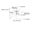
- FIG. 6 is a diagram showing a film wetting control map.
- the film wetting control map in the region I where the required load is relatively small, the required power generation amount is small and the amount of liquid water in the fuel cell can be lowered, so the target HFR takes a relatively large predetermined constant value.
- the inside of the fuel cell is controlled in a wet direction as the required load increases, and the power generation state is appropriately maintained. Accordingly, in this region II, the target HFR decreases as the required load increases.
- the target HFR within the high demand load range is set to a relatively small constant value.
- the target HFR calculator B1011 outputs the calculated target HFR.
- a value obtained by subtracting the target HFR by the HFR measurement value (hereinafter, this value is also referred to as “HFR deviation”) is input to the target water balance calculation unit B1012.
- the target water balance calculation unit B1012 calculates a target water balance based on the HFR deviation.
- the target water balance means a balance between the amount of water generated as the fuel cell stack 1 generates power and the amount of water discharged from the fuel cell stack 1 to the outside of the fuel cell system 100.
- the target water balance is a parameter representing the excess or deficiency of moisture from the target wet state in the fuel cell.
- the target water balance is a parameter representing the excess or deficiency of moisture from the target wet state in the fuel cell.
- the target is to set the value obtained by subtracting the target water balance from the actual water balance to zero.
- the target water balance calculation unit B1012 calculates the target water balance Q F_net_water based on the following equation (1).
- Q F_H2O_in Amount of water generated by power generation of fuel cell
- C C_H2O_out Cathode outlet water vapor concentration
- C C_dry_out Cathode outlet dry gas concentration
- Q C_dry_out Cathode outlet dry gas flow rate
- the cathode outlet water vapor concentration CC_H2O_out is the concentration of water vapor contained in the cathode gas at the cathode outlet of the fuel cell stack 1, and is obtained based on the following equation (2), for example.
- P CH2O_out Cathode outlet water vapor partial pressure
- P C_out Cathode outlet pressure.
- the cathode outlet water vapor partial pressure P CH2O_out is the partial pressure of water vapor contained in the cathode gas at the cathode outlet of the fuel cell stack 1, and is obtained based on, for example, the following equation (3).
- EXP means a natural logarithm.
- the cathode outlet dry gas concentration C C_dry_out is the concentration of a gas other than water vapor contained in the cathode gas at the cathode outlet of the fuel cell stack 1, and is obtained based on the following equation (4).
- the cathode outlet dry gas flow rate Q C_dry_out is a flow rate of a gas other than water vapor contained in the cathode gas at the cathode outlet of the fuel cell stack 1, and is obtained based on the following equation (5).
- Q S_in Stack supply flow rate
- Q o_exp Oxygen consumption flow rate
- the stack supply flow rate Q S_in is obtained by subtracting the bypass flow rate, which is the flow rate of the cathode gas bypassed to the bypass passage 28, from the compressor flow rate.
- the bypass flow rate can be calculated based on the bypass valve opening and the compressor flow rate using a predetermined map.
- FIG. 7 is a map showing the relationship between the bypass opening and the bypass flow rate ratio.
- the oxygen consumption flow rate Q o — exp is a flow rate of oxygen in the cathode gas consumed by an electrochemical reaction in the fuel cell stack 1.
- the oxygen consumption flow rate Q o_exp can be obtained, for example, by multiplying the required load by an oxygen consumption flow rate conversion coefficient determined in advance by experiments or the like.
- the target water balance calculation unit B1012 outputs the calculated target water balance Q F_net_water to the priority order setting unit B1013.
- the priority setting unit B1013 includes a compressor flow rate detection value, a cathode gas pressure detection value, a bypass valve opening, an atmospheric pressure detection value, and a target water balance Q calculated by the target water balance calculation unit B1012.
- F_net_water is input.
- the priority order setting unit B1013 sets priorities for adjusting each wet control parameter such as cathode gas pressure, compressor flow rate, and bypass valve opening used for wet control.
- the priority order setting unit B1013 acquires the actual water balance Q F_net_water_R from the HFR measurement value based on a predetermined water balance map. Then, the priority setting unit B1013, based on the target water balance Q F_net_water and Jitsumizu balance Q F_net_water_R, whether it is necessary to perform wet operation, it is determined whether it is necessary to carry out a dry operation.
- the priority setting unit B1013 is target water balance Q F_net_water - if it is Jitsumizu balance Q F_net_water_R> 0, it is determined that it is necessary to perform wet operation, target water balance Q F_net_water - Jitsumizu When the balance Q F_net_water_R ⁇ 0, it is determined that the dry operation needs to be performed.
- the target water balance Q F_net_water -the actual water balance Q F_net_water_R is also referred to as a water balance deviation ⁇ Q.
- the priority order setting unit B1013 outputs the water balance deviation ⁇ Q, the stack temperature, the compressor flow rate, and the bypass valve opening as the wet state control parameters to the wet control required target pressure calculation unit B1014. Furthermore, the priority order setting unit B1013 outputs the water balance deviation ⁇ Q, the stack temperature, the cathode gas pressure, and the bypass valve opening as the wet state control parameters to the wet control request target flow rate calculation unit B1015. Further, the priority order setting unit B1013 outputs the water balance deviation ⁇ Q, the stack temperature, the compressor flow rate, and the cathode gas pressure as the wet state control parameters to the target bypass valve opening degree calculation unit B1016.
- the priority order setting unit B1013 determines the wet control request target according to the determination result of whether the wet operation or the dry operation is performed based on the above-described water balance deviation ⁇ Q.
- Compressor flow rate and bypass valve opening degree output to the pressure calculation unit B1014, cathode gas pressure and bypass valve opening degree output to the wet control request target flow rate calculation unit B1015, compressor flow rate output to the target bypass valve opening degree calculation unit B1016 The cathode gas pressure is appropriately determined.
- the priority order setting unit B1013 determines the target water balance, the stack temperature, the compressor flow rate detection value as the compressor flow rate, and the bypass valve opening as 0 (fully closed). ) Is output to the wet control required target pressure calculation unit B1014.
- the priority order setting unit B1013 outputs the target water balance, the stack temperature, the cathode gas pressure detection value as the cathode gas pressure, and the value 0 as the bypass valve opening to the wet control required target flow rate calculation unit B1015.
- the priority order setting unit B1013 outputs the target water balance, the stack temperature, the compressor flow rate detection value as the compressor flow rate, and the cathode gas pressure detection value as the cathode gas pressure to the target bypass valve opening calculation unit B1016.
- the priority setting unit B1013 detects the water balance deviation, the stack temperature, the minimum flow rate as the compressor flow rate, and the bypass valve opening degree detection as the bypass valve opening degree. The value is output to the wet control required target pressure calculation unit B1014.
- the priority order setting unit B1013 outputs the target water balance, the stack temperature, the atmospheric pressure detection value as the cathode gas pressure, and the bypass valve opening detection value as the bypass valve opening to the wetting control request target flow rate calculation unit B1015.
- the priority order setting unit B1013 outputs the target water balance, the stack temperature, the minimum flow rate value as the compressor flow rate, and the atmospheric pressure detection value as the cathode gas pressure to the target bypass valve opening calculation unit B1016.
- the wet control request target pressure calculation unit B1014 calculates the wet control request target pressure based on the water balance deviation ⁇ Q, the stack temperature, the compressor flow rate, and the bypass valve opening input from the priority order setting unit B1013. .
- the wet control request target pressure calculation unit B1014 performs calculation so that the wet control request target pressure becomes higher (or lower) as the input target water balance is larger (or smaller). Further, the wet control request target pressure calculation unit B1014 performs calculation so that the wet control request target pressure becomes higher (or lower) as the input stack temperature is higher (or lower). Furthermore, the wet control request target pressure calculation unit B1014 performs calculation so that the wet control request target pressure becomes higher (lower) as the input compressor flow rate is higher (lower). Further, the wet control request target pressure calculation unit B1014 performs calculation so that the wet control request target pressure becomes lower (higher) as the input bypass valve opening is higher (lower).
- the wet control request target flow rate calculation unit B1015 calculates the wet control request target flow rate based on the target water balance, the stack temperature, the cathode gas pressure, and the bypass valve opening input from the priority setting unit B1013.
- the wet control request target flow rate calculation unit B1015 performs calculation so that the wet control request target flow rate becomes higher (or lower) as the input target water balance is larger (or smaller). Further, the wet control request target flow rate calculation unit B1015 performs a calculation so that the wet control request target flow rate becomes lower (or higher) as the stack temperature is higher (or lower). Further, the wet control request target flow rate calculation unit B1015 performs calculation so that the wet control request target flow rate becomes higher (or lower) as the input cathode gas pressure is higher (or lower). Further, the wet control request target flow rate calculation unit B1015 performs a calculation so that the wet control request target flow rate becomes higher (or lower) as the input bypass valve opening is higher (or lower).
- the target bypass valve opening calculator B1016 calculates the target bypass valve opening based on the target water balance, the stack temperature, the compressor flow rate, and the cathode gas pressure input from the priority setting unit B1013.
- the target bypass valve opening calculation unit B1016 performs calculation so that the target bypass valve opening is higher (or lower) as the input target water balance is larger (or smaller).
- the target bypass valve opening calculation unit B1016 performs calculation so that the target bypass valve opening becomes higher (or lower) as the input stack temperature is higher (or lower).
- the target bypass valve opening calculator B1016 performs calculation so that the target bypass valve opening becomes higher (or lower) as the input compressor flow rate is higher (or lower). Further, the target bypass valve opening calculation unit B1016 performs calculation so that the target bypass valve opening becomes lower (or higher) as the input cathode gas pressure is higher (or lower).
- the target water balance, the stack temperature, the atmospheric pressure detection value as the cathode gas pressure, and zero as the bypass valve opening are prioritized in the wet control required target flow rate calculation unit B1015. Input from the rank setting unit B1013.
- the atmospheric pressure detection value is the lowest value assumed as the cathode gas pressure
- the bypass valve opening being zero means that the bypass valve 29 is fully closed. Therefore, the wet control required target flow rate calculation unit B1015 calculates the wet control required target flow rate on the assumption that the cathode gas pressure is the lowest and the bypass valve opening is the lowest in the wet operation. In other words, the wet control request target flow rate is calculated as the smallest possible value for controlling the fuel cell in the wet direction.
- the target water balance, the stack temperature, the detected value of the compressor flow rate, and zero as the bypass valve opening are input to the wet control required target pressure calculation unit B1014.
- the wet control required target pressure calculation unit B1014 adjusts the compressor flow rate in the decreasing direction (wet direction of the fuel cell stack 1) by the wet control required target flow rate while setting the bypass valve opening to the lowest 0 in the wet operation.
- the wet control required target pressure is calculated using the detected value. That is, the wet control request target pressure is calculated on the assumption that the bypass valve opening is the lowest in wet operation, while the compressor flow rate is reduced to adjust the wet state. To do.
- the target water balance, the stack temperature, the detected value of the compressor flow rate, and the detected value of the cathode gas pressure are input to the target bypass valve opening calculator B1016.
- the target bypass valve opening calculation unit B1016 determines the detected value that is adjusted in the decreasing direction (wetting direction of the fuel cell stack 1) as the compressor flow rate and the wet control request as the cathode gas pressure. Based on the detected value adjusted in the increasing direction (wetting direction of the fuel cell stack 1) by the target pressure, the target bypass valve opening is calculated. In other words, the target bypass valve opening is set to a minimum by increasing the bypass valve opening on the premise that the fuel cell is controlled in the wet direction by decreasing the compressor flow rate and increasing the cathode gas pressure. Will be calculated.
- the wet control required target flow rate is calculated so that the operation of decreasing the compressor flow rate contributes most to the control in the wet direction of the fuel cell.
- the wet control required target pressure is calculated so that the operation of increasing the cathode gas pressure contributes to the control of the fuel cell in the wet direction.
- the target bypass valve opening is calculated so that the contribution to the control in the wet direction of the fuel cell by the operation of increasing the bypass valve opening is the lowest.
- the target water balance, the stack temperature, the minimum flow rate value as the compressor flow rate, and the atmospheric pressure detection value as the cathode gas pressure are input to the target bypass valve opening calculation unit B1016.
- the minimum flow rate is the compressor flow rate when the wet state of the fuel cell stack 1 is maximized. If the minimum flow rate is too low, there is a risk of power generation failure due to insufficient supply of cathode gas to the fuel cell stack 1. On the other hand, if it is too high, noise due to surging or the like may easily occur. Therefore, the lowest value is adopted as the lowest flow rate within a range in which the performance of the fuel cell stack 1 can be ensured by comprehensively considering these. This minimum flow rate is set in advance according to the operating state of the fuel cell through experiments.
- the target bypass valve opening calculation unit B1016 assumes that the compressor flow rate is the lowest flow rate and the cathode gas pressure is the atmospheric pressure detection value when controlling the fuel cell in the drying direction. Calculate the degree. That is, the target bypass valve opening calculator B1016 calculates the target bypass valve opening so that the bypass valve opening is set as small as possible.
- the target value of the water balance, the stack temperature, the minimum flow rate as the compressor flow rate, and the detected value as the bypass valve opening are input to the wet control required target pressure calculation unit B1014.
- the wet control required target pressure calculation unit B1014 decreases the compressor flow rate by the lowest flow rate value that contributes to the control of the fuel cell stack 1 to the dry side, and the bypass valve opening amount by the target bypass valve opening direction. Based on the detected value adjusted to (the drying direction of the fuel cell stack 1), the wet control required target pressure is calculated.
- the wet control required target flow rate calculation unit B1015 sets the detected value adjusted in the decreasing direction (drying direction of the fuel cell stack 1) by the target bypass valve opening as the bypass valve opening, and the wet as the cathode gas pressure. Based on the detected value adjusted in the decreasing direction (drying direction of the fuel cell stack 1) by the control request target pressure, the wet control request target flow rate is calculated.
- the bypass valve opening The dry operation with the adjustment of the highest priority is performed.
- the dry operation is performed in the priority order of decreasing the bypass valve opening, decreasing the cathode gas pressure, and increasing the compressor flow rate.
- the wet control request target pressure calculation unit B1014, the wet control request target flow rate calculation unit B1015, and the target bypass valve opening calculation unit B1016 are either in a wet operation or a dry operation. Also, the calculated wet control request target pressure and the wet control request target flow rate are output to the target pressure calculation unit B102 and the target flow rate calculation unit B103, respectively.
- the membrane wetting F / B control unit B101 is based on the target bypass valve opening calculated by the target bypass valve opening calculation unit B1016, and the bypass valve 29
- the bypass valve 29 is feedback-controlled so that the opening of the valve approaches the target bypass valve opening (see FIG. 2). That is, the bypass valve 29 is appropriately opened / closed by the membrane wetting F / B control unit B101 according to a wet operation or a dry operation performed according to the wet state of the fuel cell.
- FIG. 8 is a diagram for explaining the function of the target pressure calculation unit B102 shown in FIG.
- the target pressure calculation unit B102 includes a wet control required target pressure calculated by the membrane wet F / B control unit B101, a required load, a detected value of the anode gas pressure from the anode pressure sensor 37, and a stack temperature. Is entered. Based on these parameters, the target pressure calculation unit B102 calculates a target pressure that is a final target value of the cathode gas pressure.
- FIG. 9 is a block diagram illustrating a target pressure calculation mode in the target pressure calculation unit B102.
- the target pressure calculation unit B102 includes an oxygen partial pressure ensuring request air pressure calculation unit B1021, an excessive pressure increase prevention upper limit pressure calculation unit B1022, a maximum selection unit B1023, a minimum selection unit B1024, and a maximum selection unit B1025. And have.
- the required load is input to the oxygen partial pressure ensuring required air pressure calculation unit B1021.
- the oxygen partial pressure securing required air pressure calculation unit B1021 calculates the oxygen partial pressure securing required air pressure from a predetermined oxygen partial pressure securing required air pressure map based on the required load.
- the oxygen partial pressure ensuring required air pressure is the cathode gas determined to satisfy the oxygen concentration requirement in the fuel cell stack 1 determined to ensure the power generation of the fuel cell stack 1 according to the required load.
- the oxygen partial pressure ensuring required air pressure calculation unit B1021 outputs the calculated oxygen partial pressure ensuring required air pressure to the max select unit B1023.
- the required load and the stack temperature are input to the excessive pressure increase prevention upper limit pressure calculation unit B1022.
- the excessive pressure increase prevention upper limit pressure calculation unit B1022 calculates an excessive pressure increase prevention upper limit pressure from a predetermined excessive pressure increase prevention upper limit pressure map based on the required load and the stack temperature.
- the excessive pressure increase preventing upper limit pressure is an upper limit value of the cathode gas pressure determined from the viewpoint of preventing the cathode gas pressure from continuing to increase in wet operation and dry operation.
- the excessive pressure increase prevention upper limit pressure to be obtained increases as the required load increases.
- the excessive pressure increase prevention upper limit pressure to be obtained increases as the stack temperature increases.
- the tendency of the excessive pressure increase prevention upper limit pressure map is that the excessive pressure increase prevention upper limit pressure is set relatively high in a high load state or at a high temperature, while the excessive pressure increase prevention upper limit is set in a low load state or at a low temperature. Set the pressure relatively low.
- the excessive pressure increase prevention upper limit pressure calculation unit B1022 considers the wet state of the fuel cell stack 1 such as the target HFR or target water balance calculated by the target HFR calculation unit B1011 instead of or together with the required load and the stack temperature. Thus, an upper limit pressure for preventing excessive pressure increase may be determined. In particular, the upper limit pressure for preventing excessive pressure increase may be increased as the fuel cell stack 1 moves to the dry side.
- the excessive pressure increase prevention upper limit pressure is set relatively low in a low load state, at a low temperature, and when the fuel cell stack 1 is dried, the cathode gas pressure is maintained even when the bypass valve 29 is closed. Is suppressed from increasing excessively, the power consumption of the compressor 22 can be reduced, and it is possible to contribute to improvement of fuel consumption and suppression of noise.
- the oxygen partial pressure ensuring required air pressure calculated by the oxygen partial pressure ensuring required air pressure calculating unit B1021 and the wet control required target pressure calculated by the wet control required target pressure calculating unit B1014 are stored. Entered. Then, the maximum select unit B1023 outputs the larger one of the input oxygen partial pressure securing request air pressure and the wet control request target pressure to the minimum select unit B1024.
- both the securing of the oxygen concentration according to the request for the amount of power generation in the fuel cell stack 1 and the securing of the cathode gas pressure required in the wet control of the fuel cell stack 1 are achieved. Will be taken into account.
- the minimum pressure selection unit B1024 receives the pressure value output from the maximum selection unit B1023 and the excessive pressure increase prevention upper limit pressure calculated by the excessive pressure increase prevention upper limit pressure calculation unit B1022. The minimum selection unit B1024 outputs the smaller one of the input pressure value and the excessive pressure increase prevention upper limit pressure to the maximum selection unit B1025.
- the value output from the minimum select unit B 1024 is limited so as not to exceed the upper limit pressure for preventing excessive pressure increase while satisfying the value required for ensuring the oxygen concentration in the fuel cell stack 1 and wet control. Is considered.
- the maximum select portion B1025 receives the pressure value inputted from the minimum select portion B1024 and the transmembrane differential pressure allowable upper limit value obtained by subtracting the allowable differential pressure upper limit from the detected value of the anode gas pressure.
- the allowable upper limit of the differential pressure is the upper limit pressure allowed as the differential pressure between the anode gas pressure and the cathode gas pressure in the fuel cell stack 1 from the viewpoint of protecting the electrolyte membrane of the fuel cell. Therefore, by subtracting the upper limit of the allowable differential pressure from the detected value of the anode gas pressure, it is possible to obtain the allowable upper limit of the transmembrane differential pressure as the upper limit of the cathode gas pressure allowed from the viewpoint of protecting the electrolyte membrane of the fuel cell. it can.
- the maximum select unit B1025 sets the target flow rate calculation unit B103 and the flow rate / pressure F / B control using the larger one of the pressure value input from the minimum select unit B1024 and the transmembrane pressure differential allowable upper limit pressure as the target pressure. Output to part B104.
- the target pressure which is the final target value of the cathode gas pressure, satisfies the requirements for securing the oxygen concentration in the fuel cell stack 1 and controlling the wetness while restricting an excessive increase in the transmembrane pressure difference. It is set so as not to exceed the pressure increase prevention upper limit pressure.
- FIG. 10 is a diagram illustrating the function of the target flow rate calculation unit B103. As shown in the figure, the required flow rate, the detected value of the anode gas pressure, the stack temperature, the detected atmospheric pressure value, the wet control required target flow rate, and the target pressure are input to the target flow rate calculation unit B103. The target flow rate calculation unit B103 calculates a target flow rate that is a final target value of the compressor flow rate based on these input values.
- FIG. 11 is a block diagram illustrating a calculation mode of the target flow rate in the target flow rate calculation unit B103.
- the target flow rate calculation unit B103 includes an oxygen partial pressure ensuring lower limit flow rate calculating unit B1031, a pressure ensuring required flow rate calculating unit B1032, a purge hydrogen dilution required flow rate calculating unit B1033, and a load / oxygen consumption flow rate converting unit B1034. And a Max select portion B1035.
- the required load is input to the oxygen partial pressure ensuring lower limit flow rate calculation unit B1031.
- the oxygen partial pressure ensuring lower limit flow rate calculation unit B1031 calculates the oxygen partial pressure securing lower limit flow rate from a predetermined oxygen partial pressure securing lower limit flow rate map based on the required load.
- the oxygen partial pressure ensuring lower limit flow rate is a lower limit value of the compressor flow rate obtained in advance through experiments or the like determined from the viewpoint of satisfying the demand for oxygen concentration in the fuel cell stack 1.
- the value of the oxygen partial pressure ensuring lower limit flow to be obtained increases as the required load increases and the amount of oxygen consumed by the electrochemical reaction in the fuel cell stack 1 increases. ing.
- the lower limit value of the compressor flow rate may be determined from the viewpoint of preventing flooding and local water clogging in the fuel cell stack 1. In particular, it is preferable to set a value that can prevent flooding and local water clogging while ensuring the oxygen concentration in the fuel cell stack 1.
- the oxygen partial pressure ensuring lower limit flow rate calculation unit B1031 outputs the calculated oxygen partial pressure ensuring minimum required flow rate to the max selection unit B1035.
- the target pressure and the stack temperature from the target pressure calculation unit B102 are input to the pressure ensuring required flow rate calculation unit B1032.
- the pressure ensuring required flow rate calculation unit B 1032 calculates the pressure ensuring required flow rate from a predetermined pressure ensuring required flow rate map based on the target pressure and the stack temperature.
- the pressure ensuring required flow rate is the minimum value of the compressor flow rate required for ensuring the target pressure from the viewpoint of avoiding surging according to the stack temperature.
- the pressure ensuring required flow rate to be obtained increases as the target pressure increases. Further, in the pressure ensuring required flow rate map, the pressure ensuring required flow rate to be obtained is corrected so as to decrease as the stack temperature increases.
- the pressure ensuring request flow rate calculation unit B1032 outputs the calculated pressure ensuring request flow rate to the max select unit B1035.
- the detected value of the anode gas pressure and the detected atmospheric pressure value are input to the purge hydrogen dilution required flow rate calculation unit B1033.
- the purge hydrogen dilution request flow rate calculation unit B 1033 calculates the purge hydrogen dilution request flow rate from a predetermined purge hydrogen dilution request flow rate map based on these input parameters.
- the purge hydrogen dilution required flow rate is a compressor flow rate required for diluting the anode exhaust gas discharged from the fuel cell stack 1.
- the purge hydrogen dilution request flow to be obtained increases as the detected value of the anode gas pressure increases. This is because the higher the anode gas pressure, the greater the compressor flow rate required for dilution. Further, the purge hydrogen dilution request flow map is corrected so that the purge hydrogen dilution request flow to be obtained becomes smaller as the atmospheric pressure detection value becomes larger. This is because when the atmospheric pressure increases, the differential pressure between the cathode gas supply passage 21 and the cathode gas discharge passage 26 increases and the bypass flow rate increases, so that the purge hydrogen dilution request flow rate as the compressor flow rate can be lowered. It is.
- the required load is input to the load / oxygen consumption flow rate conversion unit B1034.
- the load / oxygen consumption flow rate conversion unit B 1034 calculates the oxygen consumption flow rate in the fuel cell stack 1 by multiplying the input requested load by a load / oxygen consumption flow rate conversion coefficient determined in advance through experiments or the like.
- the load / oxygen consumption flow rate conversion unit B 1034 may calculate the oxygen consumption flow rate based on a predetermined map that defines the relationship between the required load and the oxygen consumption flow rate in the fuel cell stack 1.
- the oxygen consumption flow rate as a correction value is added to the purge hydrogen dilution request flow rate calculated by the purge hydrogen dilution request flow rate calculation unit B1033, and the result is output to the Max Select unit B1035.
- the correction of the purge hydrogen dilution required flow rate is further improved by correcting the purge hydrogen dilution required flow rate by adding the oxygen consumption flow rate representing the oxygen flow rate consumed in the electrochemical reaction in the fuel cell stack 1.
- the Max Select unit B1035 includes a wet control request target flow rate from the wet control request target flow rate calculation unit B1015, an oxygen partial pressure ensuring lower limit flow rate calculating unit B1031, an oxygen partial pressure ensuring required air flow rate, and a pressure ensuring required flow rate calculating unit B1032.
- the flow rate required for securing the pressure and the corrected purge hydrogen flow rate required for purge are input.
- the maximum select unit B1035 is a flow rate / pressure F / B control unit with the maximum value among the target flow rate required for wet control, the required air flow rate for securing oxygen partial pressure, the required flow rate for securing pressure, and the required flow rate for purge hydrogen dilution as the target flow rate Output to B104.
- the final target flow rate is assured of the oxygen partial pressure in the fuel cell stack 1 according to the required load, the requirement in the wet control of the fuel cell stack 1, the securing of the pressure of the cathode gas to the fuel cell stack 1, And a value that satisfies all of the dilution requirements.
- FIG. 12 is a diagram illustrating the function of the flow rate / pressure F / B control unit B104.
- the flow rate / pressure F / B control unit B104 includes a target pressure calculated by the target pressure calculation unit B102, a target flow rate calculated by the target flow rate calculation unit B103, a detected value of the cathode gas pressure, and a compressor. The detection value of the flow rate is input.
- the flow rate / pressure F / B control unit B104 adjusts the compressor output and the opening of the cathode pressure regulating valve 27 based on these input values.
- the flow rate / pressure F / B control unit B104 adjusts the compressor output so that the compressor flow rate converges to the target flow rate.
- the flow rate / pressure F / B control unit B104 adjusts the opening of the cathode pressure regulating valve 27 so that the cathode gas pressure converges to the target pressure.
- FIG. 13 is a block diagram for explaining the control of the anode system in the controller 200.
- the controller 200 includes a target hydrogen pressure calculation unit B105, a hydrogen pressure regulating valve F / B control unit B106, a target HRB (Hydrogen recirculation blower) rotation number calculation unit B107, an HRBF / B control unit B108, Have
- the detected values of the required load and the cathode gas pressure are input to the target hydrogen pressure calculation unit B105.
- the target hydrogen pressure calculation unit B105 calculates a target anode gas pressure using a predetermined target anode gas pressure map based on these input values.
- the calculated target anode gas pressure and detected value of the anode gas pressure are input to the hydrogen pressure regulating valve F / B control unit B106.
- the hydrogen pressure regulating valve F / B control unit B106 controls the opening degree of the anode pressure regulating valve 33 so that the detected value of the anode gas pressure converges to the target anode gas pressure.
- the target HRB rotational speed calculation unit B107 calculates a target HRB rotational speed that is a target rotational speed of the anode gas circulation blower 36 from a predetermined target HRB rotational speed map based on the input required load.
- FIG. 14 shows an example of the target HRB rotation speed map.
- the target HRB rotation speed is set to a higher value as the required load increases, that is, as the amount of anode gas to be consumed in the electrochemical reaction in the fuel cell increases.
- the target HRB rotational speed calculated by the target HRB rotational speed calculator B107 is input to the HRBF / B controller B108.
- the HRBF / B control unit B108 controls the rotation speed of the anode gas circulation blower 36 based on the input target HRB rotation speed.
- FIG. 15 is a flowchart for explaining the wetting control of the fuel cell system 100 according to this embodiment. This control processing procedure is repeatedly executed at a predetermined control cycle.
- step S10 the controller 200 detects the operating state of the fuel cell stack 1.
- the air flow meter 23 detects the compressor flow rate and the cathode pressure sensor 25 detects the cathode gas pressure in accordance with an instruction from the controller 200.
- the opening degree sensor 29a detects the opening degree of the bypass valve 29.
- the controller 200 calculates the detected value of the stack temperature based on the detected value of the cooling water temperature by the inlet water temperature sensor 46 and the outlet water temperature sensor 47.
- step S20 the controller 200 acquires the required load of the load device 5.
- step S30 the controller 200 acquires an HFR measurement value correlated with the wet state of the electrolyte membrane from the impedance measurement device 6.
- step S40 the target HFR calculation unit B1011 (see FIG. 4) of the controller 200 calculates the target HFR based on the required load.
- step S50 the target water balance calculation unit B1012 (see FIG. 4) of the controller 200 calculates the target water balance so that the HFR measurement value converges to the target HFR, that is, based on the HFR deviation.
- step S60 the priority setting unit B1013 (see FIG. 5) of the controller 200 obtains the actual water balance from the HFR measurement value.
- step S70 the priority setting unit B1013 of the controller 200 determines whether or not to perform a wet operation. Specifically, as already described, the priority order setting unit B1013 determines the magnitude relationship between the target water balance and the actual water balance, and determines that the wet operation is performed if the target water balance ⁇ the actual water balance> 0. If not, that is, if target water balance-actual water balance ⁇ 0, it is determined that the wet operation is not performed.
- step S70 If it is determined in step S70 that a wet operation is to be performed, the controller 200 executes a wet operation process in step S80. If it is determined in step S70 that the wet operation is not performed, the controller 200 executes the dry operation in step S90.
- FIG. 16 is a flowchart for explaining the flow of the wet operation executed in step 80.
- step S81 the wet control request target flow rate calculation unit B1015 (see FIG. 5) calculates the wet control request target flow rate.
- the wet control request target flow rate calculation unit B1015 requests the wet control based on the target water balance, the stack temperature, the atmospheric pressure detection value as the cathode gas pressure, and zero as the bypass valve opening. Calculate the target flow rate.
- the wet control required target flow rate calculation unit B1015 calculates the wet control required target flow rate on the assumption that the cathode gas pressure is the lowest and the bypass valve opening is the lowest. That is, the wet control required target flow rate is calculated as the minimum value that contributes most to controlling the fuel cell in the wet direction.
- step S82 the wet control request target pressure calculation unit B1014 calculates the wet control request target pressure.
- the wet control required target pressure calculation unit B 1014 sets the wet control required target pressure based on the target water balance, the stack temperature, the detected value of the compressor flow rate, and zero as the bypass valve opening. Calculate.
- the wet control request target pressure calculation unit B1014 detects the compressor flow rate that is adjusted in the decreasing direction (wet direction of the fuel cell stack 1) by the wet control request target flow rate while setting the bypass valve opening to the lowest 0.
- the wet control required target pressure is calculated using the value.
- step S83 the target bypass valve opening calculator B1016 calculates the target bypass valve opening.
- the target bypass valve opening calculation unit B1016 calculates the target bypass valve opening based on the target water balance, the stack temperature, the detected value of the compressor flow rate, and the detected value of the cathode gas pressure. .
- the target bypass valve opening calculation unit B1016 sets the increase amount of the bypass valve opening to a minimum on the premise that the fuel cell is controlled in the wet direction by decreasing the compressor flow rate and increasing the cathode gas pressure. Thus, the target bypass valve opening is calculated.
- step S84 the controller 200 determines the compressor 22, based on the wet control request target flow calculated in step S81, the wet control request target pressure calculated in step S82, and the target bypass valve opening calculated in step S83.
- the cathode pressure regulating valve 27 and the bypass valve 29 are controlled.
- the target flow rate calculation unit B103 calculates the target flow rate according to the logic described in FIG. 11 based on the wet control request target flow rate calculated in step S81. Then, the flow rate / pressure F / B control unit B104 (see FIG. 12) adjusts the compressor output based on the calculated target flow rate and the compressor flow rate detection value.
- the target pressure calculation unit B102 calculates the target pressure according to the logic described in FIG. 9 based on the wet control required target pressure calculated in step S82. Then, the flow rate / pressure F / B control unit B104 (see FIG. 12) adjusts the cathode pressure regulating valve opening based on the calculated target pressure and cathode gas pressure detection value.
- the membrane wetting F / B control unit B101 (see FIG. 3) adjusts the bypass valve opening based on the target bypass valve opening calculated in step S83.
- the compressor flow rate determined by the target flow rate based on the wet control required target flow rate calculated with the cathode gas pressure as the atmospheric pressure detection value and the bypass valve opening as zero is the first wet control parameter with the highest priority as the wet control parameter. It becomes.
- the target flow rate is set as the maximum value among the wet control required target flow rate, the oxygen partial pressure ensuring lower limit flow rate, the pressure securing required flow rate, and the purge hydrogen dilution required flow rate.
- the flow rate does not fall below the lower limit flow rate ensuring oxygen partial pressure. Therefore, in this embodiment, the compressor flow rate is adjusted so as not to fall below the oxygen partial pressure securing lower limit flow rate.
- the cathode gas pressure determined by the target pressure based on the target pressure for the wet control calculated with the detected value of the compressor flow rate and the bypass valve opening as zero is the second highest wet control parameter as the wet control parameter. It becomes.
- the target pressure is set so as not to exceed the excessive pressure increase prevention upper limit pressure. Therefore, in this embodiment, the cathode gas pressure is adjusted so as not to exceed the excessive pressure increase prevention upper limit pressure.
- bypass valve opening determined by the target bypass valve opening calculated using the compressor flow rate as the detection value and the cathode gas pressure as the detection value is the third wet control parameter having the lowest priority as the wet control parameter.
- FIG. 17 shows a table showing the priorities of the respective wet control parameters during the wet operation and the relationship between the increase and decrease trends of these wet control parameters.
- the compressor output is lowered so that the compressor flow rate as the first wetness control parameter is reduced.
- the opening of the cathode pressure regulating valve 27 is reduced so that the cathode gas pressure as the second wetness control parameter increases.
- the bypass valve opening as the third wetness control parameter is increased so that the bypass flow rate is increased.
- the fuel cell stack 1 is controlled in the wetting direction in the priority order of decreasing the compressor flow rate, increasing the cathode gas pressure, and increasing the bypass valve opening.
- FIG. 18 is a diagram illustrating an example of a change in the state of the fuel cell system 100 during a wet operation at a certain required load.
- a straight arrow indicated by a symbol “C1” shown in the drawing represents an operation of decreasing the compressor flow rate by reducing the output of the compressor 22. That is, as is apparent from FIG. 18, in this operation, if the bypass valve opening is constant, the stack flow rate is reduced.
- the refracted arrow indicated by the symbol “C2” represents an operation for decreasing the opening degree of the cathode pressure regulating valve 27.
- a straight arrow indicated by a symbol “C3” represents an operation for increasing the bypass valve opening, that is, an operation for increasing the bypass flow rate.
- the target wet state line when the stack temperature is a certain temperature T1 and the target wet state line when the stack temperature is a certain temperature T2 are indicated by dotted lines (T1 ⁇ T2).
- a cathode system operation limit line representing the minimum value of the stack supply flow rate with respect to the cathode gas pressure determined from the viewpoint of avoiding the surging of the compressor 22 is indicated by a one-dot chain line.
- the oxygen partial pressure ensuring lower limit flow rate and the excessive pressure increase preventing upper limit pressure are indicated by broken lines.
- FIG. 18 assumes that a wet operation is performed and the operating point of the fuel cell system 100 is changed from the current operating point to the target operating point.
- the current operating point is a temperature T1 at which the stack temperature is at a certain temperature T1
- the target wet state corresponding to the temperature T1 is satisfied.
- the target wet state is a state where the water balance deviation ⁇ Q is zero.
- the target operating point is an operating point where the stack temperature is the temperature T2 (> T1) and the target wet state corresponding to the temperature T2 is satisfied. Therefore, in order to change the operating point of the fuel cell system 100 from the current operating point to the target operating point, a wet operation is performed to wet the fuel cell more.
- the compressor flow rate is decreased from the current operating point. Since the target flow rate is adjusted so as not to fall below the oxygen partial pressure ensuring lower limit flow rate as already described (see FIG. 11), the compressor flow rate (stack supply flow rate) stops decreasing at the oxygen partial pressure securing lower limit flow rate.
- the cathode gas pressure is increased. Since the target pressure is adjusted so as not to exceed the excessive pressure increase prevention upper limit pressure as already described (see FIG. 9), the cathode gas pressure stops increasing at the excessive pressure increase prevention upper limit pressure.
- the cathode gas pressure is adjusted so as not to increase beyond the excessive pressure increase prevention upper limit pressure, an excessive increase in the cathode gas pressure is suppressed.
- the compressor flow rate also increases so as to maintain the operating point at the cathode system operating limit line.
- the compressor flow rate continues to increase, the compressor output becomes high, and there is a concern that the fuel consumption will decrease due to the increase in power consumption.
- the stack supply flow rate increases, which may induce overdrying of the fuel cell stack 1.
- the cathode gas pressure is limited so as not to exceed the upper limit for preventing excessive pressure increase, thereby increasing the power consumption of the compressor 22 and causing excessive drying of the fuel cell stack 1. Can be suppressed.
- bypass valve opening is increased, the stack supply flow rate is decreased, the fuel cell is brought into the wet direction, and the fuel cell system 100 is reached at the target operating point.
- the operation for decreasing the compressor flow rate is executed in preference to the operation for increasing the bypass valve opening.
- the target flow rate is set high from the viewpoint of securing the stack supply flow rate, and consumption due to excessive increase in compressor output. Increase in electric power and generation of noise can be suppressed.
- the operation for increasing the cathode gas pressure is executed with priority over the operation for increasing the bypass valve opening. Therefore, as a result of increasing the bypass valve opening while the cathode gas pressure is low, the stack supply flow rate is reduced, and the decrease in the output voltage of the fuel cell stack 1 and the increase in the variation in the fuel cell voltage are suppressed. can do.
- FIG. 19 is a flowchart for explaining the flow of the dry operation executed in step S90 of FIG.
- the target bypass valve opening calculator B1016 calculates the target bypass valve opening. As already described in FIG. 5, in the dry operation, the target bypass valve opening calculation unit B1016 is based on the target water balance, the stack temperature, the minimum flow rate as the compressor flow rate, and the atmospheric pressure detection value as the cathode gas pressure. To calculate the target bypass valve opening.
- the target bypass valve opening calculator B1016 calculates the target bypass valve opening on the assumption that the compressor flow rate is the lowest flow rate and the cathode gas pressure is the atmospheric pressure detection value when performing the dry operation. . That is, the target bypass valve opening calculator B1016 calculates the target bypass valve opening so that the bypass valve opening is set as small as possible.
- step S92 the wet control required target pressure calculation unit B1014 calculates the wet control required target pressure.
- the wet control required target pressure calculation unit B 1014 is based on the detected value as the target water balance, stack temperature, minimum flow rate as the compressor flow rate, and bypass valve opening. The wet control required target pressure is calculated.
- the compressor flow rate is adjusted to the lowest flow rate that contributes to the control of the fuel cell stack 1 on the drying side, and the bypass valve opening is adjusted to decrease (drying direction of the fuel cell stack 1) by the target bypass valve opening. Based on the detected value, the wet control required target pressure is calculated.
- step S93 the wet control required target flow rate calculation unit B1015 calculates the wet control required target flow rate. As already described with reference to FIG. 5, the wet control required target flow rate calculation unit B 1015 wets based on the target water balance, the stack temperature, the detected value of the bypass valve opening, and the detected value of the cathode gas pressure during the dry operation. The control request target flow rate is calculated.
- the wet control request target flow rate calculation unit B1015 detects the detected value of the bypass valve opening already adjusted in the decreasing direction (drying direction of the fuel cell stack 1) by the target bypass valve opening, and the wet control request target. Based on the detected value of the cathode gas pressure that has already been adjusted in the decreasing direction (drying direction of the fuel cell stack 1) by the pressure, the wet control required target flow is calculated.
- step S94 the controller 200 determines the bypass valve 29 based on the target bypass valve opening calculated in step S91, the wet control required target pressure calculated in step S82, and the wet control required target flow calculated in step S93.
- the cathode pressure regulating valve 27 and the compressor 22 are controlled.
- the specific control mode is the same as in step S84.
- the membrane wetting F / B control unit B101 adjusts the bypass valve opening based on the target bypass valve opening calculated in step S91 (see FIGS. 3 and 5). Further, the target pressure calculation unit B102 calculates the target pressure according to the logic described in FIG. 9 based on the wet control request target pressure calculated in step S92. The flow rate / pressure F / B control unit B104 adjusts the opening of the cathode pressure regulating valve 27 based on the target pressure.
- the target flow rate calculation unit B103 calculates the target flow rate according to the logic described in FIG. 11 based on the wet control request target flow rate calculated in step S93. Then, the flow rate / pressure F / B control unit B104 adjusts the compressor output based on the target flow rate.
- the bypass valve opening determined by the target bypass valve opening calculated using the compressor flow rate as the minimum flow value and the cathode gas pressure as the atmospheric pressure detection value is the first priority as the wet control parameter. This is a dry drying control parameter.
- the cathode gas pressure determined by the target pressure based on the target pressure for the wet control calculated with the detected value of the bypass valve opening and the compressor flow rate as the minimum flow rate is the second priority as the wet control parameter.
- the second-order drying control parameter is the second-order drying control parameter.
- the compressor flow rate determined by the target flow rate based on the target flow rate for wet control calculated using the detected value of the bypass valve opening and the cathode gas pressure as the detected value has the lowest priority as the wet control parameter. This is the 3rd drying control parameter.
- FIG. 20 shows a table showing the priorities of the respective wet control parameters during the dry operation and the relationship between the increase and decrease trends of these wet control parameters.
- the bypass valve opening as the first drying control parameter is decreased so that the bypass flow rate is decreased.
- the opening of the cathode pressure regulating valve 27 is increased so that the cathode gas pressure as the second-order drying control parameter decreases.
- the compressor flow rate as the third drying control parameter is increased.
- the opening of the bypass valve is decreased in preference to the decrease in the cathode gas pressure and the increase in the compressor flow rate.
- FIG. 21 is a time chart for explaining the flow over time in an example of the wet control of the fuel cell system 100.
- FIG. 21 (a) to FIG. 21 (f) respectively show the load of the fuel cell system 100 (for example, the power supply amount or output current to each load), the stack temperature, HFR, pressure, flow rate, And the change with time of the bypass valve opening.
- the target HFR is indicated by a solid line
- the HFR measurement value is indicated by a broken line
- the target pressure is indicated by a thick solid line
- the oxygen partial pressure ensuring required pressure is indicated by a thin solid line
- the wet control required target pressure is indicated by a broken line
- the excessive pressure increase preventing upper limit pressure is indicated by a one-dot chain line.
- the transmembrane pressure differential allowable upper limit pressure is not reflected in the figure.
- the compressor flow rate is indicated by a thick solid line
- the stack supply flow rate is indicated by a thin solid line.
- the detected value of the bypass valve opening is indicated by a solid line, and the opening corresponding to when the bypass valve 29 is fully opened is indicated by a broken line.
- the fuel cell system 100 is in an idle state.
- the idle state means that the amount of power supplied from the fuel cell stack 1 to the supplementary components such as the travel motor and the compressor motor 22a is substantially zero, and the amount of power generated by the fuel cell stack 1 is relatively small. Is supplied to a battery or the like (not shown).
- the target HFR is set to a relatively high constant value in order to keep the fuel cell stack 1 relatively not wet (dry state). Therefore, the wet control is performed in a state where the target water balance is set to a relatively small constant value.
- the excessive pressure increase prevention upper limit pressure which is the upper limit value of the cathode gas pressure according to the logic described in FIG. 9 is set to a relatively low value because the required load and the stack temperature are low. (FIG. 21 (a), (b), (d)). Therefore, the cathode gas pressure takes a relatively low value corresponding to the excessive pressure increase preventing upper limit pressure. Further, as a result of the above-described wetting control, the bypass valve opening is set to a relatively small constant value (FIG. 21 (f)).
- the idle state ends, the required load and the stack temperature rise (FIGS. 21A and 21B), and the load of the fuel cell system 100 rises.
- the required load and the stack temperature increase, and the target HFR decreases (FIG. 21 (c)).
- the HFR measurement value exceeds the target HFR value. Therefore, the actual water balance becomes lower than the target water balance, and the wet operation is started to realize the target wet state.
- the cathode gas pressure which is the second-priority wet control parameter, which is prioritized
- the compressor flow rate which is the first-priority wet control parameter
- the cathode gas pressure is increased to the excessive pressure increase prevention upper limit pressure, so that the fuel cell stack 1 can be shifted in the wet direction to the required level.
- the bypass valve opening which is is still maintained.
- the increase in the load of the fuel cell system 100 is completed. Along with this, the target HFR is settled. And wetting progresses by the wet operation from the time section (ii), and the actual water balance becomes higher than the target water balance. Therefore, in the time interval (iii), the dry operation is started to achieve the target wet state.
- the bypass valve opening which is the first-order drying control parameter that is most prioritized to be operated, is set to zero according to the logic described in FIG. 5 (FIG. 21). (F)). Then, the cathode gas pressure, which is the second-order drying control parameter, is decreased so as to complement the dry operation in which the bypass valve opening is zero (FIG. 21 (d)). As a result, the cathode gas pressure is reduced to the lower limit oxygen partial pressure ensuring required pressure described with reference to FIG. By these operations, the fuel cell stack 1 can be moved in the drying direction to the required level, so that the compressor flow rate as the third-order drying control parameter is maintained (FIG. 21 (e)).
- the HFR measurement value increases as the stack temperature increases. Thereby, the actual water balance becomes lower than the target water balance, and the wet operation is started.
- the target flow rate does not decrease from the viewpoint of securing the oxygen partial pressure securing lower limit flow rate for the compressor flow rate, which is the first wet control parameter, according to the logic of FIG. Therefore, in this wet operation, the target pressure is increased in order to increase the cathode gas pressure that is the second wetness control parameter.
- the cathode gas pressure increases due to the wet operation in the time section (v). Therefore, according to the logic shown in FIG. 11, the required flow rate for pressure increase is increased, and as a result, the target flow rate is increased, so that the compressor flow rate is increased.
- the cathode gas pressure reaches the excessive pressure increase prevention upper limit pressure again as the cathode gas pressure increases due to the wet operation in the time interval (v). Therefore, according to the logic of FIG. 9, the cathode gas pressure does not increase any more.
- the increase of the bypass valve opening which is the third wetness control parameter, is started (FIG. 21 (f)). As the bypass valve opening increases, the HFR measurement value decreases so as to approach the target HFR (FIG. 21 (c)).
- the HFR measurement value continues to decrease from the time interval (vii) and settles to the target HFR (FIG. 21 (c)).
- the load is set to a high load state and the stack temperature is set to a high temperature state (FIGS. 21A and 21B).
- the compressor flow rate as the first wetness control parameter is not reduced because it is limited to the oxygen partial pressure ensuring lower limit flow rate according to the logic of FIG.
- the cathode gas pressure, which is the second wetness control parameter is limited to the excessive pressure increase prevention upper limit pressure, and therefore does not increase according to the logic of FIG. Therefore, in this wet operation, the opening degree of the bypass valve, which is the third wetness control parameter, is further increased to an opening degree corresponding to full opening (FIG. 21 (f)).
- the HFR measurement value decreases as the stack temperature decreases and the wet operation in the time interval (ix) (FIG. 21 (c)).
- the bypass valve opening which is the first dry control parameter, is decreased (FIG. 21 (f)).
- the excessive pressure increase preventing upper limit pressure decreases as the stack temperature decreases (FIG. 21D). Accordingly, the cathode gas pressure that is limited to the excessive pressure increase preventing upper limit pressure also decreases.
- the wet state of the fuel cell stack 1 is controlled by adjusting the wet control parameter in the fuel cell system 100 that supplies the fuel cell stack 1 as a fuel cell while bypassing a part of the cathode gas.
- a method for controlling the wet state of the fuel cell system 100 is provided.
- the wet state control method of the fuel cell system 100 when the wet control parameters include the bypass valve opening, the cathode gas pressure, and the compressor flow rate as the cathode gas flow rate, the fuel cell stack 1 is controlled in the wet direction. In the wet operation, the cathode gas pressure and the compressor flow rate are adjusted in preference to the adjustment of the bypass valve opening.
- the fuel cell stack 1, the compressor 22 as a cathode gas supply device that supplies cathode gas to the cathode systems 1, 2, 26, 28 including the fuel cell stack 1, and the fuel cell stack from the compressor 22 1, a bypass passage 28 for bypassing a part of the cathode gas supplied to 1, a bypass valve 29 provided in the bypass passage 28, and a membrane wet F / F as a bypass valve opening degree adjusting device for adjusting the opening degree of the bypass valve 29 B control unit B101, a cathode pressure regulating valve 27 as a cathode gas pressure adjusting device for adjusting the cathode gas pressure, and a cathode gas flow rate for adjusting the cathode gas flow rate supplied to the cathode systems 1, 2, 26, 28 by the compressor 22 Compressor motor 22a as an adjusting device and wet state of fuel cell stack 1 As an impedance measuring device 6 as a wet state acquisition device that acquires the opening degree, an opening degree sensor 29a as a bypass valve opening
- the priority setting unit B1013 controls the cathode adjustment with respect to the adjustment of the bypass valve opening by the membrane wet F / B control unit B101 when the fuel cell stack 1 is controlled in the wet direction.
- the priority order is set so that the adjustment of the cathode gas pressure by the pressure valve 27 and the adjustment of the cathode gas flow rate by the compressor motor 22a are prioritized.
- the cathode gas pressure and the compressor flow rate are adjusted in preference to the adjustment of the bypass valve opening. Therefore, it is possible to suppress the excess or deficiency of the stack supply flow rate generated by adjusting the bypass valve opening degree in the state where the compressor flow rate and the cathode gas pressure are not adjusted during the wet operation, and the wet state of the fuel cell stack 1 is preferable. Can be maintained.
- the opening degree of the bypass valve is adjusted in preference to the adjustment of the compressor flow rate and the cathode gas pressure.
- the priority order setting unit B1013 adjusts the cathode gas pressure by the cathode pressure regulating valve 27 and the cathode gas flow rate by the compressor motor 22a during the dry operation.
- the adjustment of the opening degree of the bypass valve by the membrane wetting F / B control unit B101 is given priority over at least one of the adjustments.
- the wet control parameter is adjusted to change the wet state of the fuel cell stack 1.
- a method for controlling the wet state of the fuel cell system 100 is provided that performs control so as to approach the target wet state.
- the wet control parameters include the bypass valve opening, the cathode gas pressure, and the compressor flow rate as the cathode gas flow rate.
- the compressor flow rate decreases as the cathode gas flow rate.
- increasing the cathode gas pressure, and increasing the bypass valve opening so as to complement the control of the fuel cell stack 1 in the wet direction by decreasing the compressor flow rate and increasing the cathode gas pressure.
- the increase of the bypass valve opening is preferentially executed, and the reduction of the compressor flow rate and the increase of the cathode gas pressure are executed in an auxiliary manner. Accordingly, during wet operation, the stack supply is achieved by increasing the bypass valve opening while the compressor flow rate is not decreased or the cathode gas pressure is not increased while the wet state of the fuel cell stack 1 is brought closer to the target wet state. Excessive or insufficient flow rate can be suppressed, and the wet state of the fuel cell stack 1 can be suitably maintained.
- the reduction of the compressor flow rate is executed in preference to the increase of the bypass valve opening.
- the target flow rate is set higher. Therefore, an increase in power consumption and noise due to excessive increase in compressor output can be suppressed.
- the increase in the cathode gas pressure is executed in preference to the increase in the bypass valve opening. Therefore, as a result of increasing the bypass valve opening before the cathode gas pressure increases, the supply flow rate of the cathode gas to the fuel cell stack 1 decreases, and the output voltage of the fuel cell stack 1 decreases and the fuel cell voltage decreases. An increase in variation can be suppressed.
- the controller 200 performs the wet operation for controlling the fuel cell stack 1 in the wet direction, and detects the atmospheric pressure detection value that is the minimum value of the cathode gas pressure, and opens the bypass valve.
- the bypass valve opening target value is calculated based on the cathode gas pressure detection value and the compressor flow rate detection value, and the compressor flow rate, cathode gas pressure, and bypass valve opening value are respectively determined as the wet control request target flow rate and the wet control request target value. Adjust to approach the pressure and target bypass valve opening.
- the priority of operation is determined in the order of decreasing compressor flow rate, increasing cathode gas pressure, and increasing bypass valve opening. Therefore, it is possible to more easily realize a configuration in which the bypass flow rate is not adjusted in a state where the compressor flow rate and the cathode gas pressure are not adjusted.
- the compressor flow rate increases after the bypass valve opening decreases, and therefore the cathode gas to the fuel cell stack 1 that can be generated by increasing the compressor flow before the bypass valve opening decreases. Can be prevented more reliably.
- the cathode gas pressure decreases after the bypass valve opening decreases, so that it is possible to suppress the cathode gas pressure from being reduced when the bypass flow rate is not reduced.
- the compressor output is controlled to increase so as to increase the compressor flow rate due to the decrease in the cathode gas pressure, and as a result, the increase in power consumption and the generation of noise can be further reduced.
- the controller 200 when performing the dry operation for controlling the fuel cell stack 1 in the drying direction, detects the atmospheric pressure detection value that is the lowest value of the cathode gas pressure, and the cathode gas.
- the target value of the bypass valve opening is calculated based on the minimum flow rate, which is the minimum flow rate
- the target value of the wet control is calculated based on the detected value of the bypass opening and the minimum flow rate.
- the wet control request target flow rate is calculated, and the bypass valve opening, the cathode gas pressure, and the cathode gas flow rate are respectively calculated as the target bypass valve opening and the wet control request target. Adjust pressure and wet control required flow rate to approach.
- the priority of operation is determined in the order of the decrease of the bypass valve opening, the decrease of the cathode gas pressure, and the compressor flow rate.
- a configuration in which the cathode gas pressure is decreased and the compressor flow rate is increased after the bypass valve opening is decreased can be more easily realized.
- the cathode gas pressure is limited so as not to exceed the excessive pressure increase preventing upper limit pressure as the pressure upper limit value.
- the excessive pressure increase prevention upper limit pressure is calculated based on the required load and the stack temperature which is the temperature of the fuel cell.
- the target pressure becomes higher in a high load state, etc., so that the excessive pressure increase prevention upper limit pressure is set relatively high, while in the low load state, etc., the target pressure becomes lower, so the excessive pressure increase prevention upper limit is set.
- the pressure can be set relatively low.
- the upper pressure limit for preventing excessive pressure increase is set relatively low in low load conditions or at low temperatures, excessive increase in cathode gas pressure can be suppressed, compressor output can be reduced, and fuel efficiency can be improved. And can contribute to noise suppression.
- the upper limit pressure for preventing excessive pressure increase may be calculated based on the target wet state such as the target HFR and the target water balance. Thereby, the upper limit of the cathode gas pressure can be suitably adjusted according to the target wet state of the fuel cell stack 1.
- the compressor flow rate is adjusted so as not to fall below the lower limit flow rate value (oxygen partial pressure securing lower limit flow rate) that is the lower limit value.
- the oxygen partial pressure ensuring lower limit flow rate which is the lower limit value of the flow rate, is set to satisfy the cathode gas supply flow rate (stack supply flow rate) required by the fuel cell stack 1.
- the stack supply flow rate necessary to satisfy the power generation amount corresponding to the required load is more reliably secured, the oxygen concentration in the fuel cell stack 1 is suitably maintained, and the power generation state is appropriately maintained. Is done.
- the lower limit of the flow rate may be set so as to prevent local water clogging in the fuel cell stack 1.
- the wet state of the fuel cell is further suitably maintained, overdrying and flooding are prevented, and this contributes to the maintenance of a better power generation state.
- the wet flow control is performed using the compressor flow rate as the first wet control parameter, the cathode gas pressure as the second wet control parameter, and the bypass valve opening as the third wet control parameter.
- the wet control parameter is not necessarily limited to the priority order in the above embodiment. Is not to be done. That is, the compressor flow rate may be the first wet control parameter, the bypass valve opening may be the second wet control parameter, and the cathode gas pressure may be the third wet control parameter.
- the cathode gas pressure may be the first wet control parameter, the bypass valve opening may be the second wet control parameter, and the compressor flow rate may be the third wet control parameter.
- the compressor flow rate at which the adjustment amount is maximized is given priority as the first wet control parameter, and the cathode gas pressure and bypass valve opening are prioritized.
- the degree is the second or third wetness control parameter.
- the mode of setting the priority is not limited to this.
- the compressor flow rate that is the first wet control parameter is adjusted first, and then the cathode gas pressure that is the second wet control parameter.
- the temporal priority relationship may be set for each wetness control parameter, for example, by performing adjustment of the following, and finally adjusting the opening degree of the bypass valve. Even in the dry operation, a temporal priority relationship can be set for each wetness control parameter.
- the priority order of the wetting control parameters during the dry operation is not necessarily limited to the above embodiment.
- parameters other than the compressor flow rate and the cathode gas pressure such as the HRB rotation speed, may be included as the wetting control parameters.
- each configuration of the fuel cell system 100 of the present embodiment is not limited to the above embodiment.
- the cathode pressure regulating valve 27 may be replaced with a solenoid valve and configured as a throttle portion having a fixed opening such as an orifice.
- the compressor 22 may be provided with a turbine that is driven by receiving supply of cathode gas from the cathode gas discharge passage 26 or anode gas from the high-pressure tank 31.
- the HFR measurement value in the present embodiment may be corrected by the stack temperature.
Landscapes
- Engineering & Computer Science (AREA)
- General Chemical & Material Sciences (AREA)
- Sustainable Development (AREA)
- Sustainable Energy (AREA)
- Manufacturing & Machinery (AREA)
- Chemical & Material Sciences (AREA)
- Chemical Kinetics & Catalysis (AREA)
- Electrochemistry (AREA)
- Life Sciences & Earth Sciences (AREA)
- Automation & Control Theory (AREA)
- Artificial Intelligence (AREA)
- Computing Systems (AREA)
- Evolutionary Computation (AREA)
- Fuzzy Systems (AREA)
- Medical Informatics (AREA)
- Software Systems (AREA)
- Theoretical Computer Science (AREA)
- Health & Medical Sciences (AREA)
- Fuel Cell (AREA)
Abstract
Description

QF_H2O_in:燃料電池の発電による生成水量
CC_H2O_out:カソード出口水蒸気濃度
CC_dry_out:カソード出口ドライガス濃度
QC_dry_out:カソード出口ドライガス流量
である。

PCH2O_out:カソード出口水蒸気分圧
PC_out:カソード出口圧力
である。


ただし、
QS_in:スタック供給流量
Qo_exp:酸素消費流量
である。
Claims (13)
- カソードガスの一部をバイパスさせつつ燃料電池に供給する燃料電池システムで、湿潤制御パラメータを調節して前記燃料電池の湿潤状態を制御する燃料電池システムの湿潤状態制御方法であって、
前記湿潤制御パラメータが、バイパス弁開度、カソードガス圧力、及びカソードガス流量を少なくとも含み、
前記燃料電池を湿潤方向に制御する際に、前記バイパス弁開度の調節に優先して前記カソードガス流量及び前記カソードガス圧力の少なくとも何れか一方を調節する、
燃料電池システムの湿潤状態制御方法。 - 請求項1に記載の燃料電池システムの湿潤状態制御方法であって、
前記燃料電池を乾燥方向に制御する際に、前記カソードガス流量及び前記カソードガス圧力の少なくとも何れか一方の調節に優先して、前記バイパス弁開度を調節する、
燃料電池システムの湿潤状態制御方法。 - カソードガスの一部をバイパスさせつつ燃料電池に供給する燃料電池システムで、湿潤制御パラメータを調節して前記燃料電池の湿潤状態を目標湿潤状態に近づけるように制御する燃料電池システムの湿潤状態制御方法であって、
前記湿潤制御パラメータが、バイパス弁開度、カソードガス圧力、及びカソードガス流量を少なくとも含み、
前記燃料電池を湿潤方向に制御する際には、
前記カソードガス流量の減少及び前記カソードガス圧力の増加の少なくとも何れか一方を実行し、
前記カソードガス流量の減少及び前記カソードガス圧力の増加の少なくとも何れか一方による前記燃料電池の湿潤方向への制御を補完するように、前記バイパス弁開度を増加させる、
燃料電池システムの湿潤状態制御方法。 - 請求項3に記載の燃料電池システムの湿潤状態制御方法であって、
前記燃料電池を湿潤方向に制御する際には、
前記カソードガス圧力の最低値、及び前記バイパス弁開度の最低値に基づいて前記カソードガスの湿潤制御要求目標流量を演算し、
前記カソードガス流量の検出値、及び前記バイパス弁開度の最低値に基づいて前記カソードガスの湿潤制御要求目標圧力を演算し、
前記カソードガス圧力の検出値、前記カソードガス流量の検出値に基づいて前記バイパス弁開度の目標値を演算し、
前記カソードガス流量、前記カソードガス圧力、及び前記バイパス弁開度を、それぞれ、前記湿潤制御要求目標流量、前記湿潤制御要求目標圧力、及び前記バイパス弁開度の目標値に近づくように調節する、
燃料電池システムの湿潤状態制御方法。 - 請求項3又は4に記載の燃料電池システムの湿潤状態制御方法であって、
前記燃料電池を乾燥方向に制御する際には、
前記バイパス弁開度を減少させる操作を行い、
前記バイパス弁開度の減少操作を補完するように、前記カソードガス流量の増加及び前記カソードガス圧力の減少の少なくとも何れか一方を実行する、
燃料電池システムの湿潤状態制御方法。 - 請求項5に記載の燃料電池システムの湿潤状態制御方法であって、
前記燃料電池を乾燥方向に制御する際には、
前記カソードガスの圧力の最低値、及び前記カソードガス流量の最低値に基づいて前記バイパス弁開度の目標値を演算し、
前記バイパス弁開度の検出値、及び前記カソードガス流量の最低値に基づいて前記カソードガスの湿潤制御要求目標圧力を演算し、
前記バイパス弁開度の検出値、及び前記カソードガス圧力の検出値に基づいて前記カソードガスの湿潤制御要求目標流量を演算し、
前記バイパス弁開度、前記カソードガス圧力、及び前記カソードガス流量、を、それぞれ、前記バイパス弁開度の目標値、前記湿潤制御要求目標圧力、及び前記湿潤制御要求目標流量に近づくように調節する、
燃料電池システムの湿潤状態制御方法。 - 請求項3~6の何れか1項に記載の燃料電池システムの湿潤状態制御方法であって、
前記カソードガス圧力が圧力上限値を超えないように制限される、
燃料電池システムの湿潤状態制御方法。 - 請求項7に記載の燃料電池システムの湿潤状態制御方法であって、
前記圧力上限値を、要求負荷、前記燃料電池の温度、及び目標とする湿潤状態の少なくとも何れか1つに基づいて演算する、
燃料電池システムの湿潤状態制御方法。 - 請求項3~8の何れか1項に記載の燃料電池システムの湿潤状態制御方法であって、
前記カソードガス流量がその下限値である流量下限値を下回らないように調節される、
燃料電池システムの湿潤状態制御方法。 - 請求項9に記載の燃料電池システムの湿潤状態制御方法であって、
前記流量下限値を、前記燃料電池に供給されるカソードガスの流量である燃料電池供給流量の要求を満たすように設定する、
燃料電池システムの湿潤状態制御方法。 - 請求項9又は10に記載の燃料電池システムの湿潤状態制御方法であって、
前記流量下限値を、前記燃料電池における局所水つまりを防止し得るように設定する、
燃料電池システムの湿潤状態制御方法。 - 燃料電池と、
前記燃料電池を含むカソード系にカソードガスを供給するカソードガス供給装置と、
前記カソードガス供給装置から前記燃料電池に供給されるカソードガスの一部をバイパスするバイパス通路と、
前記バイパス通路に設けられるバイパス弁と、
前記バイパス弁の開度を調節するバイパス弁開度調節装置と、
カソードガス圧力を調節するカソードガス圧力調節装置と、
前記カソードガス供給装置により前記カソード系に供給されるカソードガス流量を調節するカソードガス流量調節装置と、
前記燃料電池の湿潤状態を取得する湿潤状態取得装置と、
前記バイパス弁の開度を取得するバイパス弁開度取得装置と、
前記カソードガス圧力を取得するカソードガス圧力取得部と、
前記カソードガス流量を取得するカソードガス流量取得部と、
前記バイパス弁開度調節装置によるバイパス弁開度の調節、前記カソードガス圧力調節装置によるカソードガス圧力の調節、及び前記カソードガス流量調節装置によるカソードガス流量の調節の優先順位を設定する優先順位設定部と、
を有し、
前記優先順位設定部は、
前記燃料電池を湿潤方向に制御する際に、前記バイパス弁開度調節装置によるバイパス弁開度の調節に対して、前記カソードガス圧力調節装置によるカソードガス圧力の調節及び前記カソードガス流量調節装置によるカソードガス流量の調節の少なくとも一方が優先されるように優先順位を設定する、
燃料電池システムの湿潤状態制御装置。 - 請求項12に記載の燃料電池システムの湿潤状態制御装置であって、
前記優先順位設定部は、
前記燃料電池を乾燥方向に制御する際に、前記カソードガス圧力調節装置によるカソードガス圧力の調節及び前記カソードガス流量調節装置によるカソードガス流量の調節の少なくとも一方に対し、前記バイパス弁開度調節装置によるバイパス流量の調節を優先させる、
燃料電池システムの湿潤状態制御装置。
Priority Applications (6)
| Application Number | Priority Date | Filing Date | Title |
|---|---|---|---|
| EP16894574.9A EP3432398B1 (en) | 2016-03-15 | 2016-12-08 | Wetting state control method for fuel cell system, and wetting state control device |
| JP2018505251A JP6601556B2 (ja) | 2016-03-15 | 2016-12-08 | 燃料電池システムの湿潤状態制御方法及び湿潤状態制御装置 |
| CN201680083638.3A CN109075360B (zh) | 2016-03-15 | 2016-12-08 | 燃料电池系统的湿润状态控制方法以及湿润状态控制装置 |
| US16/084,345 US10305127B2 (en) | 2016-03-15 | 2016-12-08 | Wet state control method for fuel cell system and wet state control device for the same |
| KR1020187027297A KR102004112B1 (ko) | 2016-03-15 | 2016-12-08 | 연료 전지 시스템의 습윤 상태 제어 방법 및 습윤 상태 제어 장치 |
| CA3017437A CA3017437C (en) | 2016-03-15 | 2016-12-08 | Wet state control method for fuel cell system and wet state control device for the same |
Applications Claiming Priority (2)
| Application Number | Priority Date | Filing Date | Title |
|---|---|---|---|
| JP2016-051340 | 2016-03-15 | ||
| JP2016051340 | 2016-03-15 |
Publications (1)
| Publication Number | Publication Date |
|---|---|
| WO2017158957A1 true WO2017158957A1 (ja) | 2017-09-21 |
Family
ID=59850287
Family Applications (1)
| Application Number | Title | Priority Date | Filing Date |
|---|---|---|---|
| PCT/JP2016/086636 WO2017158957A1 (ja) | 2016-03-15 | 2016-12-08 | 燃料電池システムの湿潤状態制御方法及び湿潤状態制御装置 |
Country Status (7)
| Country | Link |
|---|---|
| US (1) | US10305127B2 (ja) |
| EP (1) | EP3432398B1 (ja) |
| JP (1) | JP6601556B2 (ja) |
| KR (1) | KR102004112B1 (ja) |
| CN (1) | CN109075360B (ja) |
| CA (1) | CA3017437C (ja) |
| WO (1) | WO2017158957A1 (ja) |
Cited By (1)
| Publication number | Priority date | Publication date | Assignee | Title |
|---|---|---|---|---|
| JP2022552867A (ja) * | 2019-10-30 | 2022-12-20 | ロベルト・ボッシュ・ゲゼルシャフト・ミト・ベシュレンクテル・ハフツング | 燃料電池システムを運転および設計するための方法 |
Families Citing this family (10)
| Publication number | Priority date | Publication date | Assignee | Title |
|---|---|---|---|---|
| DE102017222390A1 (de) * | 2017-12-11 | 2019-06-13 | Robert Bosch Gmbh | Fördereinrichtung für eine Brennstoffzellenanordnung zum Fördern und/oder Rezirkulieren von einem gasförmigen Medium |
| JP7140000B2 (ja) * | 2019-03-01 | 2022-09-21 | トヨタ自動車株式会社 | 燃料電池システム |
| US11108065B2 (en) * | 2019-06-03 | 2021-08-31 | Microsoft Technology Licensing, Llc | Fuel cell throttle |
| JP7238805B2 (ja) * | 2020-01-16 | 2023-03-14 | トヨタ自動車株式会社 | 燃料電池システム |
| CN111959253A (zh) * | 2020-07-15 | 2020-11-20 | 北汽福田汽车股份有限公司 | 冷却控制方法及系统,电动汽车 |
| CN112751061B (zh) * | 2020-12-31 | 2022-02-25 | 吉林大学 | 一种燃料电池空气路测试系统及方法 |
| CN113571746B (zh) * | 2021-06-04 | 2024-02-06 | 武汉格罗夫氢能汽车有限公司 | 一种燃料电池系统及防止电堆阳极水淹的方法 |
| CN114142064A (zh) * | 2021-12-07 | 2022-03-04 | 浙江锋源氢能科技有限公司 | 一种燃料电池增湿系统、燃料电池系统 |
| CN115295826B (zh) * | 2022-07-25 | 2023-04-18 | 上海杰宁新能源科技发展有限公司 | 一种燃料电池控制方法、系统、存储介质及智能终端 |
| DE102023201054A1 (de) * | 2023-02-09 | 2024-08-14 | Robert Bosch Gesellschaft mit beschränkter Haftung | Brennstoffzellensystem und Betriebsverfahren für ein Brennstoffzellensystem im Hochdruckbetrieb |
Citations (6)
| Publication number | Priority date | Publication date | Assignee | Title |
|---|---|---|---|---|
| JP2010114039A (ja) * | 2008-11-10 | 2010-05-20 | Toyota Motor Corp | 燃料電池システム |
| JP2012252939A (ja) * | 2011-06-06 | 2012-12-20 | Nissan Motor Co Ltd | 燃料電池の湿潤状態制御装置 |
| WO2013150651A1 (ja) * | 2012-04-06 | 2013-10-10 | トヨタ自動車株式会社 | 燃料電池システム |
| WO2013187514A1 (ja) * | 2012-06-15 | 2013-12-19 | 日産自動車株式会社 | 燃料電池システム |
| WO2014103589A1 (ja) * | 2012-12-28 | 2014-07-03 | 日産自動車株式会社 | 燃料電池システム及びその制御方法 |
| JP2016009518A (ja) * | 2014-06-20 | 2016-01-18 | 本田技研工業株式会社 | 燃料電池システムの運転方法 |
Family Cites Families (5)
| Publication number | Priority date | Publication date | Assignee | Title |
|---|---|---|---|---|
| JP2007257956A (ja) | 2006-03-22 | 2007-10-04 | Nissan Motor Co Ltd | 燃料電池システム |
| CA2838647C (en) | 2011-06-06 | 2016-02-09 | Nissan Motor Co., Ltd. | Wet state control device for fuel cell |
| JP5834594B2 (ja) * | 2011-07-28 | 2015-12-24 | 日産自動車株式会社 | 燃料電池の湿潤状態制御装置 |
| US9905867B2 (en) * | 2012-12-28 | 2018-02-27 | Nissan Motor Co., Ltd. | Fuel cell system |
| CN103050723B (zh) * | 2012-12-28 | 2014-12-24 | 清华大学 | 一种用于质子交换膜燃料电池的阴极排气再循环系统 |
-
2016
- 2016-12-08 JP JP2018505251A patent/JP6601556B2/ja active Active
- 2016-12-08 US US16/084,345 patent/US10305127B2/en active Active
- 2016-12-08 EP EP16894574.9A patent/EP3432398B1/en active Active
- 2016-12-08 CN CN201680083638.3A patent/CN109075360B/zh active Active
- 2016-12-08 WO PCT/JP2016/086636 patent/WO2017158957A1/ja active Application Filing
- 2016-12-08 CA CA3017437A patent/CA3017437C/en active Active
- 2016-12-08 KR KR1020187027297A patent/KR102004112B1/ko active IP Right Grant
Patent Citations (6)
| Publication number | Priority date | Publication date | Assignee | Title |
|---|---|---|---|---|
| JP2010114039A (ja) * | 2008-11-10 | 2010-05-20 | Toyota Motor Corp | 燃料電池システム |
| JP2012252939A (ja) * | 2011-06-06 | 2012-12-20 | Nissan Motor Co Ltd | 燃料電池の湿潤状態制御装置 |
| WO2013150651A1 (ja) * | 2012-04-06 | 2013-10-10 | トヨタ自動車株式会社 | 燃料電池システム |
| WO2013187514A1 (ja) * | 2012-06-15 | 2013-12-19 | 日産自動車株式会社 | 燃料電池システム |
| WO2014103589A1 (ja) * | 2012-12-28 | 2014-07-03 | 日産自動車株式会社 | 燃料電池システム及びその制御方法 |
| JP2016009518A (ja) * | 2014-06-20 | 2016-01-18 | 本田技研工業株式会社 | 燃料電池システムの運転方法 |
Cited By (2)
| Publication number | Priority date | Publication date | Assignee | Title |
|---|---|---|---|---|
| JP2022552867A (ja) * | 2019-10-30 | 2022-12-20 | ロベルト・ボッシュ・ゲゼルシャフト・ミト・ベシュレンクテル・ハフツング | 燃料電池システムを運転および設計するための方法 |
| JP7490055B2 (ja) | 2019-10-30 | 2024-05-24 | ロベルト・ボッシュ・ゲゼルシャフト・ミト・ベシュレンクテル・ハフツング | 燃料電池システムを運転および設計するための方法 |
Also Published As
| Publication number | Publication date |
|---|---|
| CA3017437C (en) | 2020-01-14 |
| KR20180108868A (ko) | 2018-10-04 |
| CA3017437A1 (en) | 2017-09-21 |
| KR102004112B1 (ko) | 2019-07-25 |
| US10305127B2 (en) | 2019-05-28 |
| CN109075360A (zh) | 2018-12-21 |
| JPWO2017158957A1 (ja) | 2018-12-27 |
| EP3432398A4 (en) | 2019-01-23 |
| EP3432398A1 (en) | 2019-01-23 |
| JP6601556B2 (ja) | 2019-11-06 |
| CN109075360B (zh) | 2019-10-01 |
| US20190081340A1 (en) | 2019-03-14 |
| EP3432398B1 (en) | 2020-05-27 |
Similar Documents
| Publication | Publication Date | Title |
|---|---|---|
| JP6601556B2 (ja) | 燃料電池システムの湿潤状態制御方法及び湿潤状態制御装置 | |
| CA3017700C (en) | Fuel cell system and control device therefor, and control method for fuel cell system | |
| JP6508358B2 (ja) | 燃料電池システムの制御方法及び燃料電池システム | |
| JP6477896B2 (ja) | 燃料電池システムの制御装置及び燃料電池システムの制御方法 | |
| US10581096B2 (en) | Fuel cell system | |
| JP5522309B2 (ja) | 燃料電池システム | |
| CN109390612B (zh) | 燃料电池系统及其控制方法 | |
| JP6179672B2 (ja) | 燃料電池システム及び燃料電池システムの制御方法 | |
| JP5812118B2 (ja) | 燃料電池システム | |
| JP6432675B2 (ja) | 燃料電池システム及び燃料電池システムの制御方法 | |
| JP6155596B2 (ja) | 燃料電池システム | |
| JP5983395B2 (ja) | 燃料電池システム | |
| JP6277600B2 (ja) | 燃料電池システムの制御装置 | |
| JP2010146750A (ja) | 燃料電池システム | |
| JP6790510B2 (ja) | 燃料電池システム及び燃料電池システムの制御方法 | |
| JP2014082082A (ja) | 燃料電池システム | |
| JP6512047B2 (ja) | 燃料電池システムの湿潤制御装置及び湿潤制御方法 | |
| WO2016125231A1 (ja) | 燃料電池システム及び燃料電池システムの制御方法 |
Legal Events
| Date | Code | Title | Description |
|---|---|---|---|
| WWE | Wipo information: entry into national phase |
Ref document number: 2018505251 Country of ref document: JP |
|
| ENP | Entry into the national phase |
Ref document number: 3017437 Country of ref document: CA |
|
| NENP | Non-entry into the national phase |
Ref country code: DE |
|
| ENP | Entry into the national phase |
Ref document number: 20187027297 Country of ref document: KR Kind code of ref document: A |
|
| WWE | Wipo information: entry into national phase |
Ref document number: 1020187027297 Country of ref document: KR |
|
| WWE | Wipo information: entry into national phase |
Ref document number: 2016894574 Country of ref document: EP |
|
| ENP | Entry into the national phase |
Ref document number: 2016894574 Country of ref document: EP Effective date: 20181015 |
|
| 121 | Ep: the epo has been informed by wipo that ep was designated in this application |
Ref document number: 16894574 Country of ref document: EP Kind code of ref document: A1 |