WO2013187093A1 - 携帯端末 - Google Patents
携帯端末 Download PDFInfo
- Publication number
- WO2013187093A1 WO2013187093A1 PCT/JP2013/056515 JP2013056515W WO2013187093A1 WO 2013187093 A1 WO2013187093 A1 WO 2013187093A1 JP 2013056515 W JP2013056515 W JP 2013056515W WO 2013187093 A1 WO2013187093 A1 WO 2013187093A1
- Authority
- WO
- WIPO (PCT)
- Prior art keywords
- image
- instruction image
- instruction
- cursor
- display
- Prior art date
- Legal status (The legal status is an assumption and is not a legal conclusion. Google has not performed a legal analysis and makes no representation as to the accuracy of the status listed.)
- Ceased
Links
Images


Classifications
-
- G—PHYSICS
- G06—COMPUTING OR CALCULATING; COUNTING
- G06F—ELECTRIC DIGITAL DATA PROCESSING
- G06F3/00—Input arrangements for transferring data to be processed into a form capable of being handled by the computer; Output arrangements for transferring data from processing unit to output unit, e.g. interface arrangements
- G06F3/01—Input arrangements or combined input and output arrangements for interaction between user and computer
- G06F3/02—Input arrangements using manually operated switches, e.g. using keyboards or dials
- G06F3/023—Arrangements for converting discrete items of information into a coded form, e.g. arrangements for interpreting keyboard generated codes as alphanumeric codes, operand codes or instruction codes
- G06F3/0233—Character input methods
- G06F3/0236—Character input methods using selection techniques to select from displayed items
-
- G—PHYSICS
- G06—COMPUTING OR CALCULATING; COUNTING
- G06F—ELECTRIC DIGITAL DATA PROCESSING
- G06F3/00—Input arrangements for transferring data to be processed into a form capable of being handled by the computer; Output arrangements for transferring data from processing unit to output unit, e.g. interface arrangements
- G06F3/01—Input arrangements or combined input and output arrangements for interaction between user and computer
- G06F3/02—Input arrangements using manually operated switches, e.g. using keyboards or dials
- G06F3/023—Arrangements for converting discrete items of information into a coded form, e.g. arrangements for interpreting keyboard generated codes as alphanumeric codes, operand codes or instruction codes
- G06F3/0233—Character input methods
-
- G—PHYSICS
- G06—COMPUTING OR CALCULATING; COUNTING
- G06F—ELECTRIC DIGITAL DATA PROCESSING
- G06F3/00—Input arrangements for transferring data to be processed into a form capable of being handled by the computer; Output arrangements for transferring data from processing unit to output unit, e.g. interface arrangements
- G06F3/01—Input arrangements or combined input and output arrangements for interaction between user and computer
- G06F3/03—Arrangements for converting the position or the displacement of a member into a coded form
- G06F3/033—Pointing devices displaced or positioned by the user, e.g. mice, trackballs, pens or joysticks; Accessories therefor
- G06F3/0354—Pointing devices displaced or positioned by the user, e.g. mice, trackballs, pens or joysticks; Accessories therefor with detection of two-dimensional [2D] relative movements between the device, or an operating part thereof, and a plane or surface, e.g. 2D mice, trackballs, pens or pucks
- G06F3/03547—Touch pads, in which fingers can move on a surface
-
- G—PHYSICS
- G06—COMPUTING OR CALCULATING; COUNTING
- G06F—ELECTRIC DIGITAL DATA PROCESSING
- G06F3/00—Input arrangements for transferring data to be processed into a form capable of being handled by the computer; Output arrangements for transferring data from processing unit to output unit, e.g. interface arrangements
- G06F3/01—Input arrangements or combined input and output arrangements for interaction between user and computer
- G06F3/048—Interaction techniques based on graphical user interfaces [GUI]
- G06F3/0481—Interaction techniques based on graphical user interfaces [GUI] based on specific properties of the displayed interaction object or a metaphor-based environment, e.g. interaction with desktop elements like windows or icons, or assisted by a cursor's changing behaviour or appearance
- G06F3/04812—Interaction techniques based on cursor appearance or behaviour, e.g. being affected by the presence of displayed objects
-
- G—PHYSICS
- G06—COMPUTING OR CALCULATING; COUNTING
- G06F—ELECTRIC DIGITAL DATA PROCESSING
- G06F3/00—Input arrangements for transferring data to be processed into a form capable of being handled by the computer; Output arrangements for transferring data from processing unit to output unit, e.g. interface arrangements
- G06F3/01—Input arrangements or combined input and output arrangements for interaction between user and computer
- G06F3/048—Interaction techniques based on graphical user interfaces [GUI]
- G06F3/0487—Interaction techniques based on graphical user interfaces [GUI] using specific features provided by the input device, e.g. functions controlled by the rotation of a mouse with dual sensing arrangements, or of the nature of the input device, e.g. tap gestures based on pressure sensed by a digitiser
- G06F3/0488—Interaction techniques based on graphical user interfaces [GUI] using specific features provided by the input device, e.g. functions controlled by the rotation of a mouse with dual sensing arrangements, or of the nature of the input device, e.g. tap gestures based on pressure sensed by a digitiser using a touch-screen or digitiser, e.g. input of commands through traced gestures
- G06F3/04883—Interaction techniques based on graphical user interfaces [GUI] using specific features provided by the input device, e.g. functions controlled by the rotation of a mouse with dual sensing arrangements, or of the nature of the input device, e.g. tap gestures based on pressure sensed by a digitiser using a touch-screen or digitiser, e.g. input of commands through traced gestures for inputting data by handwriting, e.g. gesture or text
-
- G—PHYSICS
- G06—COMPUTING OR CALCULATING; COUNTING
- G06F—ELECTRIC DIGITAL DATA PROCESSING
- G06F3/00—Input arrangements for transferring data to be processed into a form capable of being handled by the computer; Output arrangements for transferring data from processing unit to output unit, e.g. interface arrangements
- G06F3/01—Input arrangements or combined input and output arrangements for interaction between user and computer
- G06F3/048—Interaction techniques based on graphical user interfaces [GUI]
- G06F3/0487—Interaction techniques based on graphical user interfaces [GUI] using specific features provided by the input device, e.g. functions controlled by the rotation of a mouse with dual sensing arrangements, or of the nature of the input device, e.g. tap gestures based on pressure sensed by a digitiser
- G06F3/0488—Interaction techniques based on graphical user interfaces [GUI] using specific features provided by the input device, e.g. functions controlled by the rotation of a mouse with dual sensing arrangements, or of the nature of the input device, e.g. tap gestures based on pressure sensed by a digitiser using a touch-screen or digitiser, e.g. input of commands through traced gestures
- G06F3/04886—Interaction techniques based on graphical user interfaces [GUI] using specific features provided by the input device, e.g. functions controlled by the rotation of a mouse with dual sensing arrangements, or of the nature of the input device, e.g. tap gestures based on pressure sensed by a digitiser using a touch-screen or digitiser, e.g. input of commands through traced gestures by partitioning the display area of the touch-screen or the surface of the digitising tablet into independently controllable areas, e.g. virtual keyboards or menus
-
- G—PHYSICS
- G06—COMPUTING OR CALCULATING; COUNTING
- G06F—ELECTRIC DIGITAL DATA PROCESSING
- G06F2203/00—Indexing scheme relating to G06F3/00 - G06F3/048
- G06F2203/048—Indexing scheme relating to G06F3/048
- G06F2203/04808—Several contacts: gestures triggering a specific function, e.g. scrolling, zooming, right-click, when the user establishes several contacts with the surface simultaneously; e.g. using several fingers or a combination of fingers and pen
-
- H—ELECTRICITY
- H04—ELECTRIC COMMUNICATION TECHNIQUE
- H04M—TELEPHONIC COMMUNICATION
- H04M2250/00—Details of telephonic subscriber devices
- H04M2250/22—Details of telephonic subscriber devices including a touch pad, a touch sensor or a touch detector
-
- H—ELECTRICITY
- H04—ELECTRIC COMMUNICATION TECHNIQUE
- H04M—TELEPHONIC COMMUNICATION
- H04M2250/00—Details of telephonic subscriber devices
- H04M2250/70—Details of telephonic subscriber devices methods for entering alphabetical characters, e.g. multi-tap or dictionary disambiguation
Definitions
- the present invention relates to a mobile terminal having a character input function, such as a mobile phone, a smart phone, a personal digital assistant (PDA), and a tablet terminal.
- a character input function such as a mobile phone, a smart phone, a personal digital assistant (PDA), and a tablet terminal.
- PDA personal digital assistant
- a mobile terminal for example, a mobile phone
- many users hold the mobile phone with one hand, and operate a cursor movement instruction button or a character input button with the thumb of the hand to input characters.
- a cursor movement instruction button or a character input button with the thumb of the hand to input characters.
- the cursor movement instruction button and the character input button are provided at predetermined positions of the mobile phone, and the position of these buttons cannot be changed, so that it is difficult to operate the button especially for a person with a large or small hand or finger. was there. Further, since these mechanical buttons are provided around the display screen or the like, there is a problem that it is difficult to reduce the size of the mobile phone.
- the present invention has been made based on the above circumstances, and an object of the present invention is to provide a portable terminal capable of improving the operability at the time of inputting characters and reducing the size. It is.
- a first invention for achieving the above object is to display a character input screen having a keyboard image including a plurality of character key images on a screen of a display means with a touch panel, and use the character key images of the keyboard image.
- a portable terminal having a character input function for inputting characters, the direction of movement of the cursor displayed on the character input screen displayed in a predetermined display area on the screen of the display means is indicated and the cursor is displayed on the keyboard image.
- An instruction image display control means for controlling the display of the instruction image for instructing selection of the key image currently pointed to, and an instruction image display area for displaying the instruction image in a predetermined display area on the screen of the display means
- the touch operation is performed on the screen of the storage means for storing information and the display means, the contact position is detected, and the detection is performed.
- a position detection unit that outputs contact position information indicating a position; and when the contact position information is sent from the position detection unit, the cursor is based on the contact position information and the instruction image display area information stored in the storage unit. Whether or not the first operation for instructing the moving direction is performed on the instruction image, and whether or not the second operation for instructing the selection of the key image indicated by the cursor on the keyboard image is performed on the instruction image.
- an operation determination unit that outputs a signal indicating that the operation on the instruction image has been performed, and a first operation on the instruction image from the operation determination unit is performed.
- Cursor table that controls the movement of the cursor on the character input screen so that the cursor moves in the direction indicated by the first operation when a signal to that effect is sent If a signal indicating that a second operation has been performed on the instruction image is sent from the control means and the operation determining means, if the cursor currently points to the character key image, the character key image is associated with the character key image.
- Input control means for controlling input of characters.
- an operation of flicking or dragging the instruction image can be employed as the first operation
- an operation of tapping the instruction image can be employed as the second operation
- the instruction image indicates one or a plurality of movement direction instruction units for instructing the movement direction with respect to the cursor, and a selection instruction unit for instructing selection of a key image that the cursor currently points on the keyboard image;
- the first operation may be an operation of touching each moving direction instruction portion of the instruction image
- the second operation may be an operation of contacting the instruction image selection instruction portion.
- the flicking operation refers to the operation of paying with a finger to play the touch panel
- the dragging operation refers to the operation of tracing the touch panel with a finger
- the tapping operation refers to the operation of tapping the screen with a finger.
- a cursor is displayed on the character input screen, the moving direction of the cursor is indicated, and an instruction image for instructing selection of a key image that the cursor currently points on the keyboard image is displayed.
- This instruction image can be displayed anywhere on the screen of the display means. Therefore, the instruction image can be arranged at a position that is easy for the user to operate, so that the operability at the time of inputting characters can be improved. Can do.
- the mobile terminal since it is not necessary to provide a mechanical instruction button for operating a cursor, which is used in a conventional mobile phone, around the display screen, the mobile terminal can be downsized.
- the instruction image display control means is instructed when a change in the display position, size, or shape of the instruction image display area is instructed using a predetermined setting screen.
- the display area of the instruction image on the screen of the display means can be changed according to the contents.
- the user can change the display area of the instruction image to a position where the user can easily operate, or to a size and shape where the user can easily operate.
- the operation determination means is based on the contact position information and the instruction image display area information stored in the storage means. It is determined whether or not a drag operation has been performed after long-pressing the instruction image for a certain time. When it is determined that a drag operation has been performed after the instruction image has been pressed for a certain time or longer, the instruction image is long. A signal indicating that a drag operation has been performed along a predetermined direction after the pressing operation is output, and the instruction image display control unit performs the long-depression operation on the instruction image from the operation determination unit along the predetermined direction.
- the display position of the instruction image on the screen of the display means can be controlled so that the display position of the instruction image moves in that direction. That. Thereby, the user can easily change the display position of the instruction image at any time.
- the operation determination unit is based on the contact position information and the instruction image display area information stored in the storage unit. It is determined whether an operation for pinching in or pinching out the instruction image has been performed. When it is determined that an operation for pinching in the instruction image has been performed, a signal indicating that a pinch-in operation has been performed on the instruction image When it is determined that an operation for pinching out the instruction image has been performed, a signal indicating that the pinch-out operation has been performed for the instruction image is output, and the instruction image display control unit instructs the operation from the operation determination unit.
- the pinch-in operation refers to an operation that narrows the interval between fingers while holding the screen with two fingers
- the pinch-out operation refers to an operation that increases the interval between fingers while holding the screen with two fingers.
- the keyboard image includes a plurality of function key images
- the input control means sends a signal indicating that the second operation is performed on the instruction image from the operation determination means.
- the cursor currently points to a function key image, it is desirable to execute processing for realizing the function assigned to the function key image.
- the user can quickly select a desired function key image by performing an operation on the instruction image using the thumb of the hand or the like.
- the input control means executes processing for realizing the function assigned to the function key image when the user directly touches the function key image on the keyboard image with a finger. You may make it do. Thereby, the user can instruct
- the input control means may control input of characters to the touched character key image when the user directly touches the character key image on the keyboard image with a finger. Good. Thereby, the user can input characters by using both the character input method using the cursor and the character input method using the touch panel.
- the cursor display control means may move the cursor in units of key images when controlling the movement of the cursor on the keyboard image.
- the user can easily and accurately perform the operation of moving the cursor to the desired key image on the keyboard image, so that operation errors can be reduced.
- a small display unit with a touch panel is provided on the back surface of the portable terminal separately from the display unit, and the instruction image is displayed in a predetermined display area on the screen of the small display unit.
- the instruction image control means performs control to display the instruction image in a predetermined display area on the screen of the small display means, and the storage means displays the instruction image in the predetermined display area on the screen of the small display means.
- Instruction image display area information for display is stored, and the position detection means detects the contact position when a contact operation is performed on the screen of the small display means, and indicates the detected position The position information may be output.
- the user can operate the cursor using not only the instruction image displayed on the display means on the front side of the portable terminal but also the instruction image displayed on the small display means on the back side, so that the usability is improved. Can be achieved.
- the cursor display control means operates the instruction image for a predetermined period of time while inputting characters, with the approximate center position of the keyboard image as the reference position of the cursor.
- the cursor may be returned to the reference position when it is determined that there is no image or when it is determined that a predetermined operation has been performed on the instruction image.
- the cursor is returned to the reference position. Can do. Therefore, in this first invention, the user can easily and quickly recognize the position of the cursor by returning the cursor to the reference position, and moves the cursor from the reference position to the desired key image with a short moving distance. Therefore, character input can be performed efficiently.
- a second invention for achieving the above object is to display a character input screen having a keyboard image including a plurality of character key images on the screen of a display means with a touch panel, and use the character key image of the keyboard image.
- a portable terminal having a character input function for inputting characters
- the direction of movement of the first cursor displayed on the character input screen displayed in the predetermined display area on the screen of the display means is designated and A first instruction image for instructing selection of a key image currently indicated by one cursor on the keyboard image, and a second displayed on a character input screen displayed in a predetermined display area on the screen of the display means
- the second for instructing the direction of movement of the cursor and for selecting the key image that the second cursor currently points on the keyboard image
- Instruction image display control means for controlling display of the display image, first instruction image display area information for displaying the first instruction image in a predetermined display area on the screen of the display means, and on the screen of the display means
- Storage means for storing second instruction image display area information for
- the cursor display control means for controlling the movement of the second cursor on the character input screen so that the second cursor moves in the direction indicated by the third operation, and the operation determination means for the first instruction image.
- an operation of flicking or dragging the first instruction image is performed as the first operation
- an operation of tapping the first instruction image is performed as the second operation
- the second instruction image is flicked as the third operation.
- An operation to perform or an operation to drag, and an operation to tap the second instruction image can be employed as the fourth operation.
- the first instruction image instructs selection of one or a plurality of movement direction instruction units for instructing the movement direction of the first cursor and the key image that the first cursor currently points on the keyboard image.
- the second instruction image is one or more movement direction instruction parts for instructing the movement direction of the second cursor, and the second cursor is currently on the keyboard image.
- a selection instructing unit for instructing the selection of the pointing key image is an operation of touching each movement direction instructing unit of the first instruction image as a second operation. Indicates an operation for contacting the selection instruction portion of the first instruction image, an operation for contacting each movement direction instruction portion of the second instruction image as the third operation, and an instruction for selecting the second instruction image as the fourth operation. Contact part It is possible to adopt an operation that.
- the first cursor and the second cursor are displayed on the character input screen, the moving direction of the first cursor is indicated, and the key image currently indicated on the keyboard image by the first cursor is selected.
- a first instruction image for instructing and a second instruction image for instructing the direction of movement of the second cursor and for selecting the key image that the second cursor currently points on the keyboard image are displayed. It is displayed on the screen of the means.
- the first instruction image and the second instruction image can be displayed anywhere on the screen of the display means, and therefore the first instruction image and the second instruction image can be arranged at a position where the user can easily operate. It is possible to improve the operability when inputting characters.
- the mobile terminal since it is not necessary to provide a mechanical instruction button for operating a cursor, which is used in a conventional mobile phone, around the display screen, the mobile terminal can be downsized.
- the user can display the first instruction image when inputting characters. Since the end of the mobile terminal near the area and the end of the mobile terminal near the display area of the second instruction image are gripped by the respective hands, the mobile terminal can be stably held with both hands. . In addition, since the user can operate the first instruction image and the second instruction image using the thumbs of the respective hands while holding the portable terminal with both hands in this way, the input operation can be performed quickly and easily. Can be done accurately.
- the instruction image display control means changes the display position, size, or shape of the display area of the first instruction image or the display area of the second instruction image using a predetermined setting screen. Can be changed, the display area of the instruction image on the screen of the display means can be changed according to the instructed content. Accordingly, the user can change the display area of the first instruction image and the display area of the second instruction image to a position where the user can easily operate, or to a size / shape that can be easily operated by the user at any time.
- the operation determining means when the contact position information is sent from the position detecting means, based on the contact position information and the instruction image display area information stored in the storage means, It is determined whether or not a drag operation has been performed after long-pressing the first instruction image or the second instruction image for a certain period of time.
- the instruction image display control unit When it is determined that a drag operation has been performed along a predetermined direction after a long press operation on the instruction image, the instruction image display control unit outputs a signal from the operation determination unit.
- the display position of the instruction image moves in that direction. It is possible to control the display position of the instruction image on the screen of the display unit so. Thereby, the user can easily change the display position of each instruction image at any time.
- the operation determination means is based on the contact position information and the instruction image display area information stored in the storage means.
- the operation determination means is based on the contact position information and the instruction image display area information stored in the storage means.
- the size of the instruction image on the screen of the display unit is reduced, and a signal indicating that a pinch-out operation has been performed on the first instruction image or the second instruction image is sent from the operation determination unit.
- the size of the instruction image on the screen of the display means can be enlarged. Accordingly, the user can easily change the size of the display area of the first instruction image and the second instruction image at any time.
- the keyboard image includes a plurality of function key images
- the input control means sends a signal indicating that the second operation has been performed on the first instruction image from the operation determination means. If the first cursor is currently pointing to the function key image, a process for realizing the function assigned to the function key image is executed, and the fourth instruction for the second instruction image is executed from the operation determination means. If a signal indicating that an operation has been performed is sent, and the second cursor currently points to a function key image, processing for realizing the function assigned to the function key image may be executed. desirable. As a result, the user can quickly select a desired function key image by operating the first instruction image and the second instruction image using the thumb of each hand while holding the portable terminal with both hands. can do.
- the input control means executes processing for realizing the function assigned to the function key image when the user directly touches the function key image on the keyboard image with a finger. You may make it do. Thereby, the user can instruct
- the input control means controls input of the character to the touched character key image.
- the user can input characters by using both the character input method using the cursor and the character input method using the touch panel.
- the mobile terminal of the second invention it is desirable that at least one of the shape, color, line drawn inside, and pattern is different between the first cursor and the second cursor. Thereby, the user can easily determine which one of the first instruction image and the second instruction image corresponds to each cursor displayed on the character input screen based on the different elements. can do.
- the cursor display control means may move the cursor in units of key images when controlling the movement of the first cursor and the second cursor on the keyboard image.
- the user can easily and accurately perform an operation of moving each cursor to a desired key image on the keyboard image, thereby reducing operation errors.
- a small display means with a touch panel is provided on the back surface of the portable terminal separately from the display means, and the first instruction image and the second instruction image are respectively on the screen of the small display means.
- the instruction image control means performs control to display the first instruction image and the second instruction image in a predetermined display area on the screen of the small display means, and the storage means First instruction image display area information for displaying the first instruction image in a predetermined display area on the screen of the small display means, and a second instruction image in the predetermined display area on the screen of the small display means Second instruction image display area information for display is stored, and the position detecting means detects the contact position when the touch operation is performed on the screen of the small display means, and detects the detected position.
- Position may be output contact position information indicating a. Accordingly, the user uses not only the first instruction image and the second instruction image displayed on the display unit on the front side of the portable terminal, but also the first instruction image and the second instruction image displayed on the small display unit on the back side. Since the first cursor and the second cursor can be operated, it is possible to improve usability.
- the cursor display control means is performing character input
- the first cursor is returned to one of the reference positions and it is determined that the second instruction image has not been operated for a predetermined period of time, or for the first instruction image and / or the second instruction image in advance.
- the second cursor may be returned to the other reference position.
- the portable terminal of the first invention or the portable terminal of the second invention further comprises keyboard image display control means for controlling display of a keyboard image displayed in a predetermined display area on the screen of the display means, and the storage means Is stored keyboard display area information for displaying a keyboard image in a predetermined display area on the screen of the display means, the operation determination means when the contact position information is sent from the position detection means Based on the contact position information and the keyboard image display area information stored in the storage means, it is determined whether or not a drag operation has been performed after pressing and holding the keyboard image for a certain period of time. When it is determined that a drag operation has been performed, the keyboard image is moved in a predetermined direction after a long press operation.
- the keyboard image display control means outputs a signal indicating that the drag operation has been performed along a predetermined direction after a long press operation on the keyboard image from the operation determination means.
- the display position of the keyboard image on the screen of the display means may be controlled so that the display position of the keyboard image moves in that direction.
- the user can easily change the display position of the keyboard image on the screen of the display means at any time by a combination of a long press operation and a drag operation for a certain time or longer.
- the operation determination means is a keyboard stored in the contact position information and the storage means when the contact position information is sent from the position detection means. Based on the display area information, it is determined whether an operation of pinching in or out of the keyboard image has been performed, and when it is determined that an operation of pinching in the keyboard image has been performed, the pinch-in operation is performed on the keyboard image. When it is determined that an operation for pinching out the keyboard image is performed, a signal indicating that the pinch out operation has been performed on the keyboard image is output, and a keyboard image display control unit Is displayed when a signal indicating that a pinch-in operation has been performed on the keyboard image is sent from the operation determination means.
- the size of the keyboard image on the screen of the display means is reduced when the size of the keyboard image on the screen is reduced and a signal indicating that a pinch-out operation has been performed on the keyboard image is sent from the operation determination means. May be enlarged. Thereby, the user can easily change the size of the display area of the keyboard image at any time.
- the cursor is displayed on the character input screen, the direction of the cursor is instructed, and the instruction image for instructing the selection of the character key image currently indicated on the keyboard image is displayed. Since the instruction image can be displayed anywhere on the screen of the display means by being displayed on the screen of the display means, the instruction image can be arranged at a position where the user can easily operate. It is possible to improve the operability during the input work. In addition, since it is not necessary to provide a mechanical instruction button for operating a cursor, which is used in a conventional mobile phone, around the display screen, the mobile terminal can be downsized.
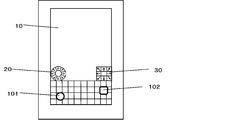
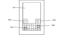
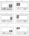
- FIG. 1 is a schematic front view of a mobile terminal according to a first embodiment of the present invention.
- FIG. 2 is a schematic block diagram of the portable terminal.
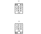
- FIG. 3 shows an example of a character input screen.
- FIG. 4 is a diagram showing an example of a keyboard image having a hiragana 50-tone arrangement.
- FIG. 5 is a diagram for explaining the first instruction image and the second instruction image.
- FIG. 6 is a diagram illustrating an example of a display mode of two cursors.
- FIG. 7 is a diagram illustrating an example of a setting screen for the first instruction image.
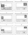
- FIG. 8 is a diagram illustrating examples of display shapes of the first instruction image and the second instruction image.
- FIG. 9 is a diagram illustrating an example of display positions of the first instruction image and the second instruction image.
- FIG. 10 is a diagram illustrating an example of display positions of the first instruction image and the second instruction image preset in advance.
- FIG. 11 is a schematic front view of a mobile terminal in which only the second instruction image is displayed on the screen.
- FIG. 12 is a diagram illustrating an example of a character input screen when only the second instruction image is displayed on the screen.
- FIG. 13 is a diagram showing an example of the display position of the second instruction image when only the second instruction image is displayed on the screen.
- FIG. 14 is a diagram showing an example of the display position of the second instruction image when only the second instruction image is displayed on the screen.
- FIG. 15 is a diagram showing an example of the display position of the second instruction image when only the second instruction image is displayed on the screen.
- FIG. 16 is a diagram illustrating an example of a display mode of the first cursor and the second cursor when the first cursor and the second cursor move in key units on the keyboard image.
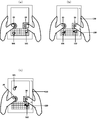
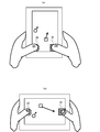
- FIG. 17 is a diagram for explaining how to hold the mobile terminal and how to operate two instruction images according to the first embodiment during a character input operation.
- FIG. 18 is a diagram for explaining how to hold the portable terminal and how to operate the first instruction image when only the first instruction image is displayed.
- FIG. 19 is a diagram for explaining how to hold the portable terminal and how to operate the second instruction image when only the second instruction image is displayed.
- FIG. 20 is a diagram illustrating another example of how to hold the mobile terminal and how to operate the instruction image.
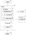
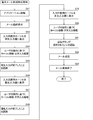
- FIG. 21 is a flowchart for explaining the processing procedure when creating an e-mail.
- FIG. 21 is a flowchart for explaining the processing procedure when creating an e-mail.
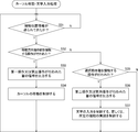
- FIG. 22 is a diagram for explaining an operation procedure on the mail transmission / creation screen when creating an electronic mail.
- FIG. 23 is a diagram for explaining an operation procedure on the mail transmission / creation screen in the case of creating an electronic mail.
- FIG. 24 is a diagram for explaining an operation procedure on the mail transmission / creation screen when creating an electronic mail.
- FIG. 25 is a flowchart for explaining the procedure of cursor movement / character input processing performed by the control means.
- FIG. 26 is a schematic front view of a mobile terminal which is a modified example of the first embodiment.
- FIG. 27 is a diagram for explaining an example of the first instruction image and the second instruction image in this modification.
- FIG. 28 is a schematic front view of a mobile terminal according to the second embodiment of the present invention.
- FIG. 26 is a schematic front view of a mobile terminal which is a modified example of the first embodiment.
- FIG. 27 is a diagram for explaining an example of the first instruction image and the second instruction image in this modification.
- FIG. 28
- FIG. 29 is a diagram for explaining an example of the first instruction image and the second instruction image in the second embodiment.
- FIG. 30 is a diagram showing an example of a QWERTY keyboard image displayed when the kanji / hiragana input mode is selected.
- FIG. 31 is a diagram showing an example of a QWERTY keyboard image displayed when the Kanji / Hiragana character input mode is selected.
- FIG. 32 is a diagram showing an example of a QWERTY keyboard image displayed when the Kanji / Hiragana character input mode is selected.
- FIG. 33 is a diagram showing an example of a QWERTY keyboard image displayed when the half-width alphabet input mode is selected.
- FIG. 30 is a diagram showing an example of a QWERTY keyboard image displayed when the kanji / hiragana input mode is selected.
- FIG. 31 is a diagram showing an example of a QWERTY keyboard image displayed when the Kanji / Hiragana character input mode is selected.
- FIG. 34 is a diagram showing an example of a QWERTY keyboard image displayed when the half-width alphabet input mode is selected.
- FIG. 35 is a diagram showing an example of a QWERTY keyboard image displayed when the half-width alphabet input mode is selected.
- FIG. 36 is a diagram showing an example of a QWERTY keyboard image displayed when the half-width alphabet input mode is selected.
- FIG. 37 is a diagram showing an example of a keyboard image with hiragana 50-tone arrangement.
- FIG. 38 is a diagram illustrating an example of display positions of the first instruction image and the second instruction image when characters are input with the mobile terminal of the first embodiment in the landscape state.
- FIG. 39 is a diagram illustrating an example of display positions of the first instruction image and the second instruction image when characters are input with the mobile terminal of the first embodiment in a horizontally long state.
- FIG. 40 shows an example of the display position of the second instruction image when characters are input while the portable terminal of the first embodiment is in a horizontally long state and only the second instruction image is displayed on the screen.
- FIG. 41 shows an example of the display position of the second instruction image when characters are input while the portable terminal of the first embodiment is in a horizontally long state and only the second instruction image is displayed on the screen.
- FIG. FIG. 42 shows an example of the display position of the second instruction image when characters are input while the portable terminal of the first embodiment is in a horizontally long state and only the second instruction image is displayed on the screen.
- FIG. FIG. 40 shows an example of the display position of the second instruction image when characters are input while the portable terminal of the first embodiment is in a horizontally long state and only the second instruction image is displayed on the screen.
- FIG. 42 shows an example of the
- FIG. 43 shows an example of the display position of the second instruction image when characters are input with the portable terminal of the first embodiment in the landscape state and only the second instruction image is displayed on the screen.
- FIG. FIG. 44 is a diagram showing an example of the display positions of the first instruction image and the second instruction image in a bi-fold type vertically long portable terminal.
- FIG. 45 is a diagram illustrating an example of the display positions of the first instruction image and the second instruction image in a bi-fold type vertically long portable terminal.
- FIG. 46 is a diagram showing an example of the display position of the second instruction image when only the second instruction image is displayed on the screen in a bi-fold type vertically long portable terminal.
- FIG. 47 is a diagram showing an example of the display position of the second instruction image when only the second instruction image is displayed on the screen in the vertically folded portable terminal of the folding type.
- FIG. 48 is a diagram showing an example of the display position of the second instruction image when only the second instruction image is displayed on the screen in a bi-fold type vertically long portable terminal.
- FIG. 49 is a diagram showing an example of the display position of the second instruction image when only the second instruction image is displayed on the screen in a vertically folded portable terminal of the folding type.
- FIG. 50 is a diagram showing an example of the display positions of the first instruction image and the second instruction image in a bi-fold type horizontally long portable terminal.
- FIG. 51 is a diagram showing an example of the display positions of the first instruction image and the second instruction image in a bi-fold type horizontally long portable terminal.
- FIG. 52 is a diagram showing an example of the display position of the second instruction image when only the second instruction image is displayed on the screen in the horizontally folded portable terminal of the folding type.
- FIG. 53 is a diagram illustrating an example of the display position of the second instruction image when only the second instruction image is displayed on the screen in a horizontally folded portable terminal of a folding type.
- FIG. 54 is a diagram showing an example of the display position of the second instruction image when only the second instruction image is displayed on the screen in a horizontally folded portable terminal of the folding type.
- FIG. 55 is a diagram showing an example of the display position of the second instruction image when only the second instruction image is displayed on the screen in the horizontally folded portable terminal of the folding type.
- FIG. 56 is a diagram showing an example of the display position of the second instruction image when only the second instruction image is displayed on the screen in the horizontally folded portable terminal of the folding type.
- FIG. 57 is a diagram showing an example of the display position of the second instruction image when only the second instruction image is displayed on the screen in a horizontally folded portable terminal of the folding type.
- FIG. 58 is a diagram showing an example of the operation of two instruction images that function as cursor operation buttons when the character input screen is not displayed on the screen of the display means.
- FIG. 59 is a diagram showing an example of the operation of two instruction images that function as cursor operation buttons when a character input screen is not displayed on the screen of the display means.
- FIG. 60 is a diagram showing an example of a keyboard image included in the telephone number input screen when the telephone number input screen is used as the character input screen.
- FIG. 61 is a diagram showing an example of a keyboard image with a Spanish layout.
- FIG. 62 is a diagram showing an example of a French keyboard image.
- FIG. 63 is a diagram showing an example of a keyboard image with a Korean layout.
- FIG. 64 is a diagram showing an example of the display position of the instruction image when the mobile terminal according to the present invention is a half-fold mobile phone.
- FIGS. 65 (a) to 65 (c) are diagrams showing a first modification of the first instruction image in the first embodiment
- FIGS. 65 (d) to (f) are second instruction images in the first embodiment.
- 66 (a) to 66 (c) are diagrams showing a second modification of the first instruction image in the first embodiment
- FIGS. 66 (d) to (f) are second instruction images in the first embodiment.
- 67 (a) to 67 (c) are diagrams showing a first modification of the first instruction image in the modification of the first embodiment
- FIGS. 67 (d) to (f) are modifications of the first embodiment.
- FIGS. 68A to 68C are views showing a second modification of the first instruction image in the modification of the first embodiment
- FIGS. 68D to 68F are a modification of the first embodiment.
- FIGS. 69A to 69C are diagrams showing modifications of the first instruction image in the first embodiment.
- FIGS. 69D to 69F are modifications of the second instruction image in the first embodiment.
- FIG. FIGS. 70A to 70C are diagrams showing modifications of the first instruction image in the modification of the first embodiment, and FIGS.
- 70D to 70F are views of modifications of the first instruction image in the modification of the first embodiment. It is a figure which shows the modification of a 2 instruction
- 71 (a) to 71 (c) are diagrams showing modifications of the first instruction image in the second embodiment, and FIGS. 71 (d) to (f) are modifications of the second instruction image in the second embodiment.
- FIG. 72 (a) to 72 (c) are diagrams showing modifications of the first instruction image in the first embodiment, and FIGS. 72 (d) to (f) are modifications of the second instruction image in the first embodiment.
- FIGS. 73 (a) to 73 (c) are diagrams showing modifications of the first instruction image in the modification of the first embodiment, and FIGS.
- FIGS. 74 (d) to (f) are modifications of the second instruction image in the second embodiment.
- FIG. FIG. 75A is a diagram showing a modification example of the first instruction image and the second instruction image in the first embodiment
- FIG. 75B is a diagram showing the first instruction image and the second instruction image in the modification example of the first embodiment.
- FIG. 76A is a diagram showing a modification of the first instruction image and the second instruction image in the first embodiment
- FIG. 76B is a diagram showing the first instruction image and the second instruction image in the modification of the first embodiment.
- FIG. 76A is a diagram showing a modification of the first instruction image and the second instruction image in the first embodiment
- FIG. 76B is a diagram showing the first instruction image and the second instruction image in the modification of the first embodiment.
- the same figure (c) is a figure which shows the modification of the 1st instruction
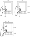
- FIG. 77 is a diagram illustrating an example of a mobile terminal in which a part of the rear portion of the mobile terminal slides in the vertical direction.
- FIG. 78 is a diagram illustrating an example of a mobile terminal in which the entire rear portion of the mobile terminal slides in the vertical direction.
- FIG. 79 is a diagram illustrating another example of the mobile terminal in which a part of the rear portion of the mobile terminal slides in the vertical direction.
- FIG. 80 is a diagram illustrating another example of the mobile terminal in which the entire rear portion of the mobile terminal slides in the vertical direction.
- FIG. 81 is a diagram showing an example of an instruction image when a two-fold mobile phone is used as the mobile terminal of the present invention.
- FIG. 82 is a diagram illustrating an example of a first instruction image and a second instruction image having six moving direction instruction units.
- FIG. 83 is a diagram illustrating an example of a keyboard image in which key images are arranged obliquely.
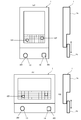
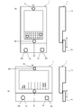
- FIG. 1 is a schematic front view of a mobile terminal according to the first embodiment of the present invention
- FIG. 2 is a schematic block diagram of the mobile terminal.
- the mobile terminal of the first embodiment is a tablet terminal that can carry and handle various types of information, such as a communication function for transmitting and receiving information to and from the outside connected to the Internet, a character input function for inputting characters, etc. It has various functions. As shown in FIGS. 1 and 2, the portable terminal includes a display unit 10, a plurality of operation buttons (not shown), a storage unit 40, a communication unit 50, a control unit 60, and a touch panel 70. . The portable terminal is formed in a substantially rectangular shape when viewed from the front.
- the various operation buttons include various buttons such as a power button.
- the power button is for turning on / off the mobile terminal, and is provided on, for example, a side surface of the mobile terminal.
- the display means 10 is provided on the front side of the mobile terminal.
- a liquid crystal display device is used as the display means 10, and a touch panel 70 is provided on the screen of the display means 10.
- the touch panel 70 detects a contact position when a touch operation is performed on the screen of the display means 10, and outputs position information indicating the detected position to the control means 60.
- Various screens such as a home screen, an application screen, and a character input screen are displayed on the screen of the display means 10.
- the home screen is a screen displayed when the mobile terminal is turned on.
- An icon of each application program is displayed on the application screen. By tapping a desired icon with a finger, that is, by tapping, the application program corresponding to the icon can be activated.
- the character input screen includes a keyboard image.
- the user can input characters using the key image of the keyboard image.
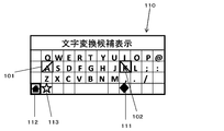
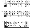
- FIG. 3 shows an example of a character input screen.
- the character input screen 100 includes a keyboard image 110 and an input character display screen 120.
- Examples of the input character display screen 120 include a search screen, a mail creation / transmission screen, and the like.
- Examples of the input character display screen 120 include Microsoft Word (registered trademark), Microsoft Excel (registered trademark), Microsoft PowerPoint (registered trademark), Microsoft Outlook (registered trademark), Microsoft Word for Mac (registered trademark), Microsoft Examples include screens using office software such as Excel for Mac (registered trademark), Microsoft PowerPoint for Mac (registered trademark), Microsoft Outlook for Mac (registered trademark), and Google Document (registered trademark).
- the keyboard image 110 is provided with a plurality of character key images associated with each character (including symbols) and a plurality of function key images to which specific functions are given. Character key images and function key images are collectively referred to as key images.
- the “character key image” is also simply referred to as “character key”
- the “function key image” is also simply referred to as “function key”.
- the “key image” is also simply referred to as “key”.
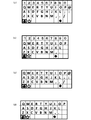
- the QWERTY layout is adopted as the layout of the character keys.
- the function keys include a character input mode switching key 111, a home key 112, a keyboard switching key 113, a space key, an Enter key, a Shift key, and the like.
- the character input mode switching key 111 is for switching between a Chinese character hiragana input mode and a half-width alphabet input mode.
- the home key 112 is used to instruct to end the character input screen 100 and display the home screen.
- the keyboard switching key 113 is used to switch between the keyboard image having the QWERTY layout shown in FIG. 3 and the keyboard image having the 50 hiragana layout.
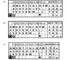
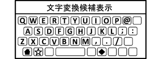
- FIG. 4 shows an example of a keyboard image of hiragana 50-tone arrangement.
- the keyboard image of the hiragana 50-sound arrangement is a keyboard image dedicated to Kanji hiragana input, and is also provided with a home key 112 and a keyboard switching key 113.
- the Kanji hiragana input mode is selected in the keyboard image of the QWERTY layout, and when the keyboard image of the hiragana 50 sound layout is displayed as the keyboard image, as shown in FIG. 3 and FIG.
- a character conversion candidate display unit 115 for displaying input character conversion candidates is displayed above the keyboard image. 3 and 4 showing the keyboard image, the space key, Enter key, Shift key, etc. are not shown. The point that illustration of these keys is omitted is the same in the drawings showing other types of keyboard images described later.
- the keyboard switching key 113 switches between the keyboard image of the QWERTY layout and the keyboard image of the 50 hiragana layout.
- An image may be adopted, and the keyboard switching key 113 may be used to switch between a QWERTY keyboard image and a simple hiragana keyboard image.
- the character input mode switching key 111 is used to switch between the Chinese character hiragana input mode and the half-width alphabet input mode. The input mode may be switched between a plurality of added input modes.
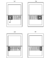
- the character input screen 100 is displayed in a vertically long state on the screen of the display means 10, and the user inputs characters with the portable terminal in a vertically long state.
- the first instruction image 20 and the second instruction image 30 are displayed on the screen.
- the first instruction image 20 and the second instruction image 30 are each displayed in a predetermined area on the screen of the display means 10.
- the first instruction image 20 and the second instruction image 30 are displayed side by side on the upper side of the keyboard image 110, and the first instruction image 20 is an input character display screen.
- the second instruction image 30 is displayed at the lower right corner of the input character display screen 120 at the lower left corner of 120.
- two cursors are displayed on the character input screen 100, the first cursor 101 is used using the first instruction image 20, and the second instruction image 30 is used.
- the second cursor 102 is to be operated.
- the first cursor 101 and the second cursor 102 are mainly used for selecting each key of the keyboard image 110. That is, the first instruction image 20 is for instructing the moving direction of the first cursor 101 and for instructing the selection of the key that the first cursor 101 currently points on the keyboard image 110.
- the image 30 is for instructing the moving direction of the second cursor 102 and for instructing the selection of the key that the second cursor 102 currently points on the keyboard image 110.
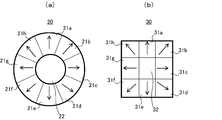
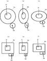
- FIG. 5 is a diagram for explaining the first instruction image 20 and the second instruction image 30.
- the first instruction image 20 is provided at the center of the eight movement direction instruction units 21a, 21b,..., 21h and the movement direction instruction units 21a, 21b,.
- a selection instruction unit 22 The eight movement direction instruction sections 21a, 21b,..., 21h are formed in an annular shape as a whole.
- Each moving direction instruction unit 21 a, 21 b,..., 21 h is for instructing a moving direction for the first cursor 101 displayed on the character input screen 100.
- the moving direction is indicated by an arrow in each moving direction instruction section 21a, 21b,..., 21h.
- the first cursor 101 moves upward on the character input screen 100, and when the user taps the movement direction instruction unit 21e, the first cursor 101 moves on the character input screen 100. Move down.
- the first cursor 101 moves right on the character input screen 100, and when the user taps the movement direction instruction unit 21g, the first cursor 101 moves on the character input screen 100. Move left.
- the user taps the movement direction instruction unit 21b the first cursor 101 moves in the upper right direction on the character input screen 100.
- the movement direction instruction unit 21d the first cursor 101 moves to the character input screen 100.
- the selection instructing unit 22 is mainly for instructing selection of a key (character key, function key) that the first cursor 101 currently points on the keyboard image 110. This selection instruction unit 22 can also be used when a key on the input character display screen 120 is selected.
- the second instruction image 30 has eight movement direction instruction units 31a, 31b,..., 31h and the movement direction instruction units 31a, 31b,. And a selection instruction unit 32 provided.
- the eight movement direction instruction sections 31a, 31b,..., 31h are formed in a square ring shape as a whole.
- Each moving direction instruction unit 31 a, 31 b,..., 31 h is for instructing the moving direction of the second cursor 102 displayed on the character input screen 100.
- the movement directions are indicated by arrows on the movement direction instruction sections 31a, 31b,.
- the second cursor 102 moves upward on the character input screen 100, and when the user taps the movement direction instruction unit 31e, the second cursor 102 moves on the character input screen 100. Move down.
- the second cursor 102 moves right on the character input screen 100, and when the user taps the movement direction instruction unit 31g, the second cursor 102 moves on the character input screen 100. Move left.
- the second cursor 102 moves diagonally right upward on the character input screen 100, and when the user taps the movement direction instruction unit 31d, the second cursor 102 moves to the character input screen 100.
- the selection instructing unit 32 is mainly for instructing selection of a key (character key or function key) that the second cursor 102 currently points on the keyboard image 110.
- the selection instruction unit 32 can also be used when a key on the input character display screen 120 is selected.
- the first instruction image 20 and the second instruction image 30 are formed in different shapes, but the first instruction image 20 and the second instruction image 30 are formed in the same shape. Also good.
- a predetermined time (hereinafter also referred to as no-operation time), when the first instruction image 20 is not operated, or When a predetermined operation is performed on the first instruction image 20 and / or the second instruction image 30, the first cursor 101 is moved (returned) to the reference position of the cursor, and a predetermined time ( No operation time), when the second instruction image 30 is not operated, or when a predetermined operation is performed on the first instruction image 20 and / or the second instruction image 30, the second cursor 102 Can be moved (returned) to the reference position of the cursor.
- Such cursor return control is performed by the control means 60.
- the reference position of the cursor is the approximate center position of each keyboard image when the keyboard image is divided into left and right, that is, when the keyboard image 110 is divided into a left keyboard image and a right keyboard image. This is the approximate center position of each divided keyboard image.
- the vicinity of the key image of “K” is the reference position of the second cursor 102.
- the manner of division is not divided into two, and the keyboard image may be divided in any way. Specifically, in the first embodiment, the following operation is defined as the operation for returning the cursor to the reference position.
- the operation of returning the cursor to the reference position according to the present invention is not limited to the above-described operation, and any operation can be performed using the first instruction image 20 and / or the second instruction image 30. It may be a thing.
- the entire surface of the character input screen 100 can be moved freely. That is, the first cursor 101 and the second cursor 102 can be moved in the same manner as a mouse cursor is moved by a normal mouse operation. For this reason, for example, when the mail creation / transmission screen is displayed as the input character display screen 120, the first cursor 101 or the second cursor 102 is moved to the send button in the mail creation / transmission screen, It can be used to select the send button.
- the first instruction image 20 and the second instruction image 30 serve as cursor operation buttons when the character input screen 100 is displayed on the screen of the display means 10.
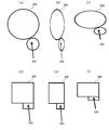
- FIG. 6 is a diagram showing an example of the display mode of the two cursors 101 and 102.
- the first cursor 101 is displayed in a circular shape
- the second cursor 102 is displayed in a rectangular shape.
- the first cursor 101 is displayed with a straight arrow heading in the upper left direction
- the second cursor 102 is displayed with a curved arrow heading from the downward direction to the upward direction.
- the first cursor 101 is displayed in a square shape
- the second cursor 102 is displayed in a shape in which a horizontal line is drawn inside the square.
- the first cursor 101 is displayed in a shape with diagonal lines inside the rectangle
- the second cursor 102 is displayed in a rectangle shape.
- the first cursor 101 is displayed in a shape drawn with a cross in the ellipse, and the second cursor 102 is displayed in a shape drawn in a cross inside the ellipse.
- the first cursor 101 is displayed in a square shape, and the second cursor 102 is displayed in a shape in which a pattern is drawn inside the square.
- the first cursor 101 is displayed in a circular shape, and the second cursor 102 is displayed in a shape in which a pattern is drawn inside a circle.
- the first cursor 101 is displayed in a circular shape and the second cursor 102 is displayed in a rectangular shape.
- a plurality of types of display modes of the first cursor 101 and the second cursor 102 are preset, and the user can select a desired one for each of the first cursor 101 and the second cursor 102. It is possible to select a display mode.
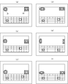
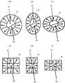
- FIG. 7 is a diagram illustrating an example of a setting screen for the first instruction image 20.
- the setting screen 400 shown in FIG. 7 includes a size selection unit 410 for selecting the size of the first instruction image 20, a shape selection unit 420 for selecting the shape of the first instruction image 20, A position selection unit 430 for selecting the display position of the instruction image 20 is provided.
- the shapes that can be selected by the shape selection unit 420 there are six shapes of “square”, “vertically long rectangle”, “horizontal rectangle”, “circle”, “vertically long ellipse”, and “horizontal ellipse”.
- positions that can be selected by the position selection unit 430 there are a total of nine positions such as “upper left”, “middle upper”, and “upper right”.
- the user can change the size of the first instruction image 20 by selecting a desired size in the size selection unit 410, and can select the first shape by selecting a desired shape in the shape selection unit 420.
- the shape of the instruction image 20 can be changed.
- the user can change the display position of the first instruction image 20 by selecting a desired position in the position selection unit 430.
- the second instruction image 30 is also provided with a setting screen similar to the setting screen 400 shown in FIG. Note that information such as the size of the first instruction image 20 or the second instruction image 30 set using the setting screen as shown in FIG. 7 is stored in the storage unit 40 described later.
- each instruction image 20, 30 can be changed using a predetermined setting screen.
- the instruction images 20 and 30 having a size corresponding to the size of his / her finger can be selected.
- the instruction images 20 and 30 having a shape corresponding to the position can be selected.
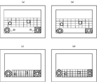
- FIG. 8 is a diagram illustrating examples of display shapes of the first instruction image 20 and the second instruction image 30.
- the first instruction image 20 is displayed in the shape of a vertically long ellipse
- the second instruction image 30 is displayed in the shape of a vertically long rectangle.
- the first instruction image 20 is displayed in the shape of a horizontally long ellipse
- the second instruction image 30 is displayed in the shape of a horizontally long rectangle.
- the display positions of the first instruction image 20 and the second instruction image 30 can be changed using a predetermined setting screen. Thereby, the user can change the position where the first instruction image 20 and the second instruction image 30 are displayed to a position where the user can easily operate the instruction images 20 and 30.
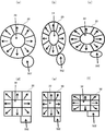
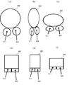
- FIG. 9 is a diagram illustrating examples of display positions of the first instruction image 20 and the second instruction image 30.
- the first instruction image 20 is displayed on the upper left portion of the input character display screen 120
- the second instruction image 30 is displayed on the upper right portion of the input character display screen 120.
- the first instruction image 20 is displayed at the center on the left side of the input character display screen 120, and the second instruction image 30 is displayed at the center on the right side of the input character display screen 120.
- the first instruction image 20 is displayed on the lower left part of the input character display screen 120, and the second instruction image 30 is displayed on the lower right part of the input character display screen 120.
- FIG. 9D when a horizontally long shape is selected as the shape of the first instruction image 20 and the second instruction image 30, the first instruction image 20 is displayed on the upper left portion of the input character display screen 120.
- the second instruction image 30 is displayed on the upper right side of the input character display screen 120.
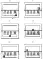
- a plurality of types of display modes of the first instruction image 20 and the second instruction image 30 are preset in advance, and the user can change the display modes of the first instruction image 20 and the second instruction image 30 from the preset ones. You may make it select. Also, the display positions of the first instruction image 20 and the second instruction image 30 on the screen of the display means 10 are preset in advance in association with the display position of the keyboard image 110, and the user has preset the display positions. A desired display position may be selected from those.
- FIG. 10 shows an example of display positions of the first instruction image 20 and the second instruction image 30 which are preset in advance.
- FIG. 11 is a schematic front view of a mobile terminal in which only the second instruction image 30 is displayed on the screen
- FIG. 12 shows an example of a character input screen when only the second instruction image 30 is displayed on the screen.
- FIGS. 13, 14 and 15 show examples of the display position of the second instruction image 30 when only the second instruction image 30 is displayed on the screen.
- the present embodiment using the predetermined setting screen, setting of an operation for moving the first cursor 101 and the second cursor 102 to the reference position, setting of the reference position for each cursor, and setting of the no-operation time, respectively. Or enabling / disabling of a function for returning each cursor to the reference position can be set.
- information such as a reference position for each cursor set using the setting screen is stored in the storage unit 40.
- the storage means 40 stores an OS and various application programs.
- the storage means 40 is used as a working memory.
- the storage means 40 includes keyboard display area information (position information, shape information, size information, color information, etc.) for displaying the keyboard image 110 in a predetermined display area on the screen of the display means 10.
- 21h of the first instruction image 20 and a selection instruction part 22 for displaying the eight movement direction instruction parts 21a, 21b, ..., 21h and the selection instruction part 22 in a predetermined display area on the screen of the display means 10.
- Instruction image display area information (including position information, shape information, size information, color information, etc.), eight movement direction instructions of the second instruction image 30 in a predetermined display area on the screen of the display means 10
- Second instruction image display area information (including position information, shape information, size information, color information, etc.) for displaying the sections 31a, 31b,.
- One cursor 1 Cursor display area information (position information, shape information, size information, color) for displaying the cursor at a predetermined display position (display area) on the screen of the display means 10 for each of the first and second cursors 102 (Including pattern information, etc.), information relating to the function of returning each cursor to its reference position (including reference position information, no-operation time information, etc.) and the like are stored.
- the communication means 50 is for communicating information with the outside.
- the control means 60 controls each part of the mobile terminal in an integrated manner. In the following, control contents related to character input will be mainly described among the contents of control performed by the control means 60. As shown in FIG. 2, the control unit 60 includes a display control unit 61, an operation determination unit 62, and an input control unit 63.
- the display control means 61 creates various screens / images such as a home screen, an application screen, a character input screen 100, a first instruction image 20 and a second instruction image 30, a first cursor 101 and a second cursor 102, and the like. It is displayed on the screen of the display means 10.
- the display control means 61 displays the keyboard image 110, the instruction images 20, 30 and the cursors 101, 102 on the screen of the display means 10 when displaying the keyboard image 110, the instruction images 20, 30 and the cursors 101, 102 on the screen of the display means 10.
- Display area information keyboard display area information, first instruction image display area information, second instruction image display area information, each cursor display area information
- the display control means 61 includes an instruction image display control means 61a, a cursor display control means 61b, and a keyboard image display control means 61c.
- the instruction image display control unit 61 a controls display of the first instruction image 20 and the second instruction image 30.
- the cursor display control means 61b controls the display of the cursors 101 and 102, and controls the movement of the cursors 101 and 102 based on a signal from the operation determination means 62 as described below.
- the keyboard image display control means 61c controls the display of the keyboard image 110.
- the instruction image display control means 61a is instructed to change the display position, size, shape, etc. of the display area of the first instruction image 20 or the display area of the second instruction image 30 using a predetermined setting screen.
- the display area of the instruction image on the screen of the display means 10 is changed according to the instructed content. Furthermore, the instruction image display control means 61a controls switching between the display of the two instruction images 20 and 30 and the display of one of the instruction images according to the content set using a predetermined setting screen.
- the display control means 61 is instructed to change the display area of the keyboard image 110, each instruction image 20, 30, and each cursor 101, 102, the display area information stored in the storage means 40 is changed. Rewrite the contents of.
- the operation determination unit 62 determines the content of the contact operation of the touch panel 70 by the user when the contact position information is output from the position detection unit 71 of the touch panel 70. Specifically, for example, when the contact position information is sent from the position detection unit 71 of the touch panel 70, the operation determination unit 62 receives the instruction image display region information (first instruction image display region information, first information stored in the storage unit 40).
- the first operation is an operation (for example, a tap operation or a long press operation) for touching each movement direction instruction unit 21a, 21b,..., 21h of the first instruction image 20, and the second operation is a first operation.
- the operation of contacting the selection instruction unit 22 of the one instruction image 20 (for example, a tap operation)
- the third operation is an operation of contacting each movement direction instruction unit 31a, 31b
- the fourth operation is an operation (for example, a tap operation) for touching the selection instruction unit 32 of the second instruction image 30.
- the third operation on the second instruction image 30 is performed while the third operation is performed.
- a signal to that effect is output to the cursor display control means 61b.
- the operation determination unit 62 determines that the second operation has been performed on the first instruction image 20
- the operation determination unit 62 outputs a signal indicating that the second operation has been performed on the first instruction image 20 to the input control unit 63. If it is determined that the fourth operation on the second instruction image 30 has been performed, a signal indicating that the fourth operation has been performed on the second instruction image 30 is output to the input control means 63.
- the operation determination unit 62 determines that the position indicated by the contact position information is not included in the display areas of the instruction units of the instruction images 20 and 30, the position indicated by the contact position information corresponds to each of the keyboard images 110. It is determined whether the position corresponds to the key. When the operation determination unit 62 determines that the position indicated by the contact position information is a position corresponding to the key, the operation determination unit 62 determines that the key has been operated (tap operation), and outputs a signal indicating that the key has been operated. Output to the input control means 63.
- the cursor display control unit 61b is subject to the first operation while the signal is being transmitted.
- the movement of the first cursor 101 on the character input screen is controlled so that the first cursor 101 moves in the movement direction indicated by the movement direction instruction section that has become, and the operation determination unit 62 applies the second instruction image 30 to the second instruction image 30.
- the second cursor 102 is moved in the movement direction indicated by the movement direction instruction unit that is the target of the third operation while the signal is transmitted.
- the movement of the second cursor 102 on the character input screen is controlled so as to move.
- the corresponding cursor moves by a minute distance in the direction indicated by the movement direction instruction section, and the user moves the desired movement direction instruction section.
- the cursor display control means 61b uses the first instruction image 20 and / or the second instruction image 30 as a reference based on the signal from the operation determination means 62 when inputting characters.
- the corresponding cursor is moved so that the corresponding cursor returns to its reference position.
- the instruction image display control means 61a changes the first instruction image 20 and the second instruction image according to the contents of the change.
- the display mode of the bi-directional image 30 is changed and displayed on the screen of the display means 10.
- the instruction image display control means 61a changes the first instruction image 20 and the first instruction image 20 according to the contents of the change.
- the display position of the second instruction image 30 is changed and displayed on the screen of the display means 10.
- the instruction image display control means 61a displays the first instruction image 20 and the first cursor 101 on the screen of the display means 10. Do not display above.
- the cursor can be freely moved (free movement setting) and the cursor is moved in units of keys with each key as one movement range.
- Setting key unit movement setting
- a setting screen similar to the setting screen shown in FIG. 7 may be used to select one of the free movement setting and the key unit movement setting, or a specific key image may be selected. You may enable it to switch a free movement setting and a key unit movement setting mutually whenever it taps. Information about which of the free movement setting and the key unit movement setting is currently valid is stored in the storage unit 40.
- the cursor display control means 61b operates the movement direction instruction units 21a, 21b,..., 21h or the movement direction instruction units 31a, 31b,. Then, the movement of the cursor is controlled so that the cursor is moved in key units along the movement direction indicated by the operated movement direction instruction section. Thereby, for example, when the user taps a desired movement direction instruction part of the first instruction image or the second instruction image, the cursor corresponding to the instruction image is adjacent to the movement direction indicated by the movement direction instruction part. When the user presses and holds a desired movement direction indicating portion of the first instruction image or the second instruction image, the cursor corresponding to the instruction image is moved by the long pressing operation.
- the key unit movement setting When the key unit movement setting is enabled, when an operation for returning each cursor to its reference position using the first instruction image 20 and / or the second instruction image 30 is performed, or When each instruction image is not operated for a predetermined time set in advance, in the case of the keyboard image 110 having the QWERTY layout shown in FIG. 3, the first cursor is set to the position of the key image “D”, and the second cursor is set to “ It is possible to return to the position of the key image “K”.
- FIG. 16 is a diagram illustrating an example of a display mode of the first cursor 101 and the second cursor 102 when the first cursor 101 and the second cursor 102 move in units of keys on the keyboard image 110.
- the first cursor 101 is displayed with a diagonal line from the upper right to the lower left inside the rectangle
- the second cursor 102 has an oblique line from the upper left to the lower right inside the rectangle. It is displayed in a drawn form.
- the key unit movement setting becomes effective. Even in this case, the user can easily identify the first cursor 101 and the second cursor 102.
- the input control means 63 controls character input and performs processing according to various commands. Specifically, the input control means 63 indicates that the first cursor 101 is currently pointing to a character key when a signal indicating that the second operation on the first instruction image 20 has been performed is sent from the operation determination means 62. If the first cursor 101 currently points to a function key, the process for realizing the function assigned to the function key is performed. Execute. Further, the input control means 63, if a signal indicating that the fourth operation on the second instruction image 30 has been performed is sent from the operation determination means 62, if the second cursor 102 currently points to the character key. , Control the input of the character associated with the character key, and on the other hand, if the second cursor 102 currently points to the function key, execute processing for realizing the function assigned to the function key .
- the input control means 63 is a character key. If there is, the input of the character associated with the character key is controlled. If the key is a function key, a process for realizing the function assigned to the function key is performed.
- the touch panel 70 is provided on the screen of the display means 10, the character input method using the first cursor 101 and the second cursor 102 and the character input method using the touch panel 70 are used in combination.
- the function key selection method using the first cursor 101 and the second cursor 102 and the function key selection method using the touch panel 70 are used together to instruct the realization of the function assigned to the function key. can do.
- a plurality of operations are defined as operations for converting and confirming the input characters.
- One operation is the same as a normal operation. That is, the input control means 63 is in the unconfirmed state displayed in the predetermined column of the input character display screen 120 when the space key of the keyboard image 110 is selected when the Kanji / Hiragana input mode is selected. The input character is converted, and the converted character is displayed on the character conversion candidate display unit 115. When the Enter key is selected, the unconfirmed input character is confirmed as the character displayed on the character conversion candidate display unit 115.
- selection of the space key or the Enter key can be performed using the first cursor 101 or the second cursor 102, or can be performed by directly touching with a finger by using the touch panel 70.
- the second operation and the fourth operation are simultaneously performed, that is, the selection instruction unit 22 of the first instruction image 20 and the selection instruction unit 32 of the second instruction image 30 are simultaneously tapped once.
- the input control means 63 converts the input characters. Specifically, the input control means 63 simultaneously receives a signal from the operation determination means 62 that the second operation on the first instruction image 20 has been performed and a signal that the fourth operation on the second instruction image 30 has been performed. When it is determined that it has been sent, input characters are converted.
- tapping the selection instruction portion of one of the first instruction image 20 and the second instruction image 30 twice in succession is performed twice.
- tapping the selection instruction unit 22 of the first instruction image 20 and the selection instruction unit 32 of the second instruction image 30 twice simultaneously is performed twice.
- the input control means 63 also determines the conversion of the input character by performing the operation of simultaneously performing two consecutive times twice). Specifically, the input control means 63 outputs a signal indicating that the second operation on the first instruction image 20 has been performed from the operation determination means 62 or a signal indicating that the fourth operation on the second instruction image 30 has been performed.
- the conversion of the input character is confirmed.
- a plurality of operations are defined as operations for converting and confirming input characters, as described above. .
- the operation for converting and confirming the input character is not limited to the above operation.
- the input control means 63 performs character conversion, and the first instruction image
- the input control means 63 may confirm the conversion of input characters by tapping the selection instruction unit 22 of the image 20 and the selection instruction unit 32 of the second instruction image 30 once at the same time.
- the operation of tapping three times is an operation of designating a command for moving the first cursor 101 and the second cursor 102 to the respective reference positions.
- the input control means 63 outputs a signal for displaying the home screen to the display control means 61 when the home key 112 of the keyboard image 110 is selected even during the input operation.
- the display control unit 61 displays the home screen on the screen of the display unit 10 instead of the character input screen 100.
- FIG. 17 is a diagram for explaining how to hold the mobile terminal and how to operate the two instruction images 20 and 30 according to the first embodiment during the character input operation.
- the user presses the left side or the back side of the mobile terminal with a finger other than the thumb of the left hand and places the thumb of the left hand above the first instruction image 20. Then, the right side or back surface of the portable terminal is pressed with a finger other than the thumb of the right hand, and the thumb of the right hand is placed above the second instruction image 30.
- the peripheral part of the part of the portable terminal provided with the first instruction image 20 and the peripheral part of the part of the portable terminal provided with the second instruction image 30 are held by the respective hands, The terminal can be stably held with both hands.
- the operation of each instruction image 20, 30 is performed with the thumb arranged above. That is, as shown in FIGS.
- the user operates each movement direction instruction unit of the first instruction image 20 using the thumb of the left hand while holding the mobile terminal with both hands.
- the first cursor 101 is moved by (tap operation, long press operation).
- the user moves the second cursor 102 by operating (tapping operation, long-pressing operation) each movement direction instruction section of the second instruction image 30 using the thumb of the right hand.
- the first instruction image 20 and the second instruction image 30 can be operated with both hands, so that desired character keys and function keys can be selected quickly and accurately, so that the input operation can be performed quickly and accurately. Can do.
- the cursors 101 and 102 can be moved not only within the display area of the keyboard image 110 but also within the display area of the input character display screen 120.
- the shape of the cursor may be automatically changed to a shape such as an arrow. Also in this case, it is desirable to change the first cursor 101 and the second cursor 102 to different shapes or different colors so that they can be distinguished from each other.
- how to hold the portable terminal and how to operate the two instruction images 20 and 30 at the time of character input work are not limited to the above methods.
- the user may hold the mobile terminal in a manner suitable for him / her and operate each of the instruction images 20 and 30 using, for example, a thumb or an index finger.
- the user while holding the mobile terminal with both hands, the user operates one instruction image using the thumb of one hand and inputs characters using only the cursor corresponding to the instruction image. Also good.
- FIG. 18 is a diagram for explaining how to hold the mobile terminal and how to operate the first instruction image 20 when only the first instruction image 20 is displayed.
- FIG. 19 is a diagram when only the second instruction image 30 is displayed. It is a figure for demonstrating how to hold a portable terminal and the operation method of the 2nd instruction
- FIG. 19 is a diagram for demonstrating how to hold a portable terminal and the operation method of the 2nd instruction
- the first instruction image 20 is displayed at the lower left corner of the input character display screen 120.
- the user presses the left side or the back side of the portable terminal with a finger other than the thumb of the left hand and places the thumb of the left hand above the first instruction image 20.
- the operation of the first instruction image 20 is performed with the thumb arranged above it. That is, as illustrated in FIGS. 18B and 18C, the user operates (tap operation, long press operation) each movement direction instruction unit of the first instruction image 20 using the thumb of the left hand.
- the first cursor 101 is moved.
- the second instruction image 30 is displayed at the lower right corner of the input character display screen 120. In this case, as shown in FIG.
- the user presses the left side or the back side of the portable terminal with a finger other than the thumb of the right hand and places the thumb of the right hand above the second instruction image 30.
- the operation of the second instruction image 30 is performed with the thumb arranged above it. That is, as shown in FIGS. 19B and 19C, the user operates (tap operation, long press operation) each movement direction instruction section of the second instruction image 30 using the thumb of the right hand.
- the second cursor 102 is moved.
- FIG. 20 shows another example of how to hold the mobile terminal and how to operate the instruction image.
- the second instruction image 30 is arranged on the center line of the input character display screen 120. If the portable terminal is a small one, the user can operate the second instruction image 30 using, for example, the thumb of the right hand as shown in FIG. In addition, as shown in FIG. 20B, the user may hold the mobile terminal with the left hand and operate the second instruction image 30 using the index finger of the right hand.
- FIG. 21 is a flowchart for explaining the processing procedure when creating an e-mail.
- FIG. 22 to FIG. 24 are diagrams for explaining the operation procedure on the mail transmission / creation screen when creating an electronic mail.
- the control means 60 activates the application program (S11).
- the display control means 61 of the control means 60 displays the mail transmission / creation screen 100a, the first instruction image 20, the second instruction image 30, and the second instruction image on the screen of the display means 10 as shown in FIG.
- One cursor 101 and the second cursor 102 are displayed (S12).
- the first instruction image 20 is displayed at the lower left corner of the input character display screen
- the second instruction image 30 is displayed at the lower right corner of the input character display screen.
- the display control means 61 stores and manages the display area information about the keyboard image 110, the instruction images 20 and 30, and the cursors 101 and 102 in the storage means 40.
- the mail transmission / creation screen 100a includes a keyboard image 110 and a message creation / display screen 120a as an input character display screen.
- the message creation display screen 120a includes a destination input field 121, a destination input completion button 122, a title input field 123, a title input completion button 124, a body text input field 125, and a send button 126.
- the destination input field 121 is a field for inputting the mail address of the other party to which the mail is transmitted.
- the destination input completion button 122 is a button for instructing that the input in the destination input field 121 is completed.
- the title input field 123 is a field for inputting the title of the mail.
- the title input completion button 124 is a button for instructing that the input in the title input field 123 is completed.
- the text input field 125 is a field for inputting a mail text.
- the send button 126 is a button for instructing to send mail. 22 to 24, the destination input completion button 122 is provided in the vicinity of the destination input field 121 and the title input completion button 124 is provided in the vicinity of the title input field 123. For example, these completion buttons 122 and 124 are provided. May be provided in the keyboard image 110.
- the display control means 61 displays an input position cursor (not shown) in the destination input field 121 (S13).
- the input position cursor indicates a field in which characters can be input and indicates a character input position.
- the user operates each instruction unit of the instruction images 20 and 30 to input a mail address in the destination input field 121.
- the user operates the movement direction instruction unit of the first instruction image 20 to place the first cursor 101 at the character key associated with the character “a” in the keyboard image.
- the selection instruction unit 22 of the first instruction image 20 is tapped.
- the control means 60 performs cursor movement / character input processing according to the operation content of the instruction images 20 and 30 by the user (S14).
- the display control unit 61 uses the signal sent from the operation determination unit 62 that the first operation on the first instruction image 20 has been performed and the signal that the third operation on the second instruction image 30 has been performed. Based on this, the movement of the first cursor 101 and the second cursor 102 is controlled, and the input control means 63 sends a signal indicating that the second operation is performed on the first instruction image 20 sent from the operation determination means 62 and Based on a signal indicating that a fourth operation has been performed on the bi-directional image 30, the input of characters and the like are controlled.
- the user moves the second cursor 102 to the destination input completion button 122, for example, as shown in FIG. By tapping 32, the destination input completion button 122 is selected.
- the input control means 63 receives a signal from the operation determination means 62 that the fourth operation has been performed on the second instruction image 30, and the destination input is When the completion is recognized (S15), the input position cursor is displayed in the title input field 123 (S16). As a result, the field where characters can be input is switched from the destination input field 121 to the title input field 123.
- the user operates the instruction units of the instruction images 20 and 30 to input a title in the title input field 123.
- the control means 60 performs cursor movement / character input processing according to the operation content of the instruction images 20 and 30 by the user (S17).
- the user moves the second cursor 102 to the title input completion button 124, for example, as shown in FIG. By tapping 32, the title input completion button 124 is selected.
- the input control means 63 receives from the operation determination means 62 a signal indicating that the fourth operation has been performed on the second instruction image 30, and receives the title
- an input position cursor is displayed in the text input field 125 (S19).
- the field in which characters can be input is switched from the title input field 123 to the text input field 125.
- the control means 60 performs cursor movement / character input processing according to the operation content of the instruction images 20 and 30 by the user (S20).
- the user moves the first cursor 101 to the transmission button 126, for example, and moves the selection instruction unit 22 of the first instruction image 20 as shown in FIG.
- the transmission button 126 is selected by tapping.
- the input control unit 63 receives a signal indicating that the second operation on the first instruction image 20 has been performed from the operation determination unit 62, and the transmission button is selected.
- FIG. 25 is a flowchart for explaining the procedure of cursor movement / character input processing performed by the control means 60.
- a case is considered where the user operates the first instruction image 20 and the second instruction image 30 to input characters.
- the operation determination unit 62 determines whether contact position information has been sent from the position detection unit 71 of the touch panel 70 (S31). If the operation determination means 62 determines that the contact position information has not been sent, whether or not the time during which the first instruction image 20 is not operated has passed a fixed time (no operation time), and whether the second instruction image 30 is It is determined whether the non-operating time has passed a certain time (no operation time). When the operation determination unit 62 determines that the time during which the instruction image is not operated has passed a certain time (no operation time), the operation determination unit 62 outputs a signal to that effect to the cursor display control unit 61b. The cursor display control unit 61b Based on the signal, the corresponding cursor is returned to the reference position.
- step S31 the process proceeds to step S31.
- the operation determination unit 62 determines that the contact position information has been sent in the process of step S31
- the movement direction of the first instruction image 20 is based on the instruction image display area information stored in the storage unit 40. It is determined whether or not an operation for touching the instruction unit or the movement direction instruction unit of the second instruction image 30 has been performed (S32).
- the operation determination unit 62 determines that an operation for touching the moving direction instruction unit of the first instruction image 20 has been performed, the fact that the first operation has been performed on the first instruction image 20 while the operation is being performed. Is output to the cursor display control means 61b, and when it is determined that an operation for touching the moving direction instruction portion of the second instruction image 30 is performed, the third instruction for the second instruction image 30 is performed while the operation is performed. A signal indicating that the operation has been performed is output to the cursor display control means 61b (S33). Then, the cursor display control means 61b controls the movement of the first cursor 101 or the second cursor 102 based on the signal (S34).
- the cursor display control unit 61b determines that the first operation target is being transmitted while the signal is being transmitted.
- the movement of the first cursor 101 is controlled on the character input screen 100 so that the first cursor 101 moves in the movement direction indicated by the movement direction instruction section.
- the cursor display control means 61b determines that the third operation is being performed while the signal is being sent.
- the movement of the second cursor 102 is controlled on the character input screen 100 so that the second cursor 102 moves in the movement direction indicated by the movement direction instruction section.
- the cursor display control means 61b determines based on the signal from the operation determination means 62 that an operation for returning each cursor to the reference position using the instruction images 20 and 30 is performed, the corresponding cursor is displayed. Is returned to its reference position.
- the operation determination unit 62 has performed an operation for touching the selection instruction unit 22 of the first instruction image 20 or the selection instruction unit 32 of the second instruction image 30. It is determined whether or not (S35).
- the operation determination unit 62 determines that an operation for touching the selection instruction unit 22 of the first instruction image 20 has been performed, the operation determination unit 62 outputs a signal to the input control unit 63 that the second operation for the first instruction image 20 has been performed. If it is determined that an operation for touching the selection instruction unit 32 of the second instruction image 30 has been performed, a signal indicating that the fourth operation for the second instruction image 30 has been performed is output to the input control means 63 (S36). . Based on the signal, the input control means 63 controls the input of characters and performs a process for realizing a predetermined function (S37).
- the input control unit 63 indicates that the first cursor 101 currently indicates a character key when a signal indicating that the second operation on the first instruction image 20 has been performed is sent from the operation determination unit 62. If so, the character associated with the character key is displayed at the position currently indicated by the input position cursor, and a signal indicating that the fourth operation has been performed on the second instruction image 30 has been sent. In this case, if the second cursor 102 currently points to the character key, the character associated with the character key is displayed at the position currently indicated by the input position cursor.
- the input control means 63 indicates that the first cursor 101 is currently pointing to a function key when a signal indicating that the second operation on the first instruction image 20 has been performed is sent from the operation determination means 62. For example, when processing for realizing the function assigned to the function key is performed and a signal indicating that the fourth operation on the second instruction image 30 has been performed is received, the second cursor 102 is currently If a function key is indicated, processing for realizing the function assigned to the function key is performed.
- the input control unit 63 converts the input character in the unconfirmed state, The converted character is displayed on the character conversion candidate display unit 115.
- an underline is added to an input character in an unconfirmed state.
- the input control means 63 displays the input character in the unconfirmed state as a character conversion candidate display. The characters displayed on the part 115 are fixed.
- the means 63 performs conversion on the input character in the unconfirmed state and causes the character conversion candidate display unit 115 to display the converted character.
- the signal indicating that the second operation on the first instruction image 20 has been performed and the signal indicating that the fourth operation on the second instruction image 30 has been performed are sent simultaneously and twice consecutively from the operation determination unit 62. If there is an unconfirmed input character at the position indicated by the input position cursor, the input control means 63 converts the unconfirmed input character to the character displayed on the character conversion candidate display unit 115. Determine.
- the first cursor and the second cursor are displayed on the character input screen, the first instruction image for instructing the moving direction of the first cursor, the moving direction of the second cursor, and the like.
- Each of the second instruction images for instructing is displayed on the screen of the display means.
- These first instruction image and second instruction image can be displayed anywhere on the screen of the display means.
- the instruction image display control means when a change in the display position, size or shape of the display area of the first instruction image or the display area of the second instruction image is instructed, Accordingly, the display area of the instruction image on the screen of the display means is changed.
- the user can change the display area of the first instruction image and the display area of the second instruction image to a position or size / shape that is easy for the user to operate at any time.
- the operability can be improved.
- the mobile terminal since it is not necessary to provide a mechanical instruction button for operating the cursor, which is used in a conventional mobile phone, around the display screen, the mobile terminal can be reduced in size. .
- the user can At the time of input, since the end of the mobile terminal near the display area of the first instruction image and the end of the mobile terminal near the display area of the second instruction image are gripped by the respective hands, Can be held stably.
- the user can operate each instruction unit of the first instruction image and each instruction unit of the second instruction image by using the thumb of each hand while holding the portable terminal with both hands in this way. Therefore, the input operation can be performed quickly and accurately.
- the user operates the instruction units of the first instruction image and the instruction units of the second instruction image using the thumbs of the respective hands while holding the portable terminal with both hands, and performs a desired function. Key images can be selected quickly.
- the portable terminal of the first embodiment in a first cursor and a second cursor, shape, color, line drawn inwardly, at least one element among the elements of the patterns are different.
- the cursor displayed on the character input screen the different based on factors, easily determine whether it corresponds to any of the instruction image of the first instruction image and the second instruction image can do.
- the cursor display control means can move the cursor in key units when controlling the movement of the first cursor and the second cursor on the keyboard image.
- the user can easily and accurately perform an operation of moving each cursor to a desired key on the keyboard image, thereby reducing operation errors.
- the mobile terminal of the first embodiment when an operation for returning each cursor to the reference position using each instruction image is performed, or when the first instruction image or the second instruction image is set in advance. When not operated, the corresponding cursor can be returned to its reference position. Therefore, in the first embodiment, the user can easily and quickly recognize the position of the cursor by returning each cursor to the reference position, and each cursor is moved from the reference position to a desired key image with a short moving distance. Since it can move by, character input can be performed efficiently.
- FIG. 26 is a schematic front view of a mobile terminal which is a modification of the first embodiment
- FIG. 27 is a diagram for explaining examples of the first instruction image 20a and the second instruction image 30a in this modification. In this modification, as shown in FIGS.
- the first instruction image 20a is provided at the center of the movement direction instruction unit 21 configured in an annular shape and the movement direction instruction unit 21.
- the second instruction image 30 a includes a movement direction instruction unit 31 configured in a square ring shape, and a selection instruction unit 32 provided in the center of the movement direction instruction unit 31.
- the movement direction instruction unit 21 of the first instruction image 20a in this modification is obtained by eliminating the division of the eight movement direction instruction units of the first instruction image 20 in the first embodiment.
- the movement direction instruction unit 31 of the second instruction image 30a in this modification is obtained by eliminating the division of the eight movement direction instruction units of the second instruction image 30.
- the roles of the selection instruction units 22 and 32 in this modification are the same as those in the first embodiment.
- the overall shape of the first instruction image 20a and the second instruction image 30a is not limited to a circle or a square.
- the overall shape of the first instruction image 20a and the second instruction image 30a may be a horizontally long elliptical shape or a horizontally long rectangular shape, or FIG. As shown in c), the shape may be a vertically long ellipse or a vertically long rectangle.
- the storage means stores first instruction image display area information (position information, shape for displaying the movement direction instruction section 21 and the selection instruction section 22 of the first instruction image 20a in a predetermined display area on the screen of the display means 10.
- First instruction image display area information position information, shape for displaying the movement direction instruction section 21 and the selection instruction section 22 of the first instruction image 20a in a predetermined display area on the screen of the display means 10.
- Information, size information, color information, etc.) for displaying the movement direction instruction section 31 and the selection instruction section 32 of the second instruction image 30a in a predetermined display area on the screen of the display means 10.
- Second instruction image display area information (including position information, shape information, size information, color information, etc.) is stored.
- the operation determination means of the control means is configured to display instruction image display area information (first instruction image display area information, second instruction image display area information) stored in the storage means. ), Whether the first operation for instructing the moving direction of the first cursor 101 has been performed on the first instruction image 20a, or the third operation for instructing the moving direction of the second cursor 102 is performed in the second instruction image. It is determined whether or not it has been performed for 30a.
- the first operation is an operation (for example, a tap operation or a long press operation) that contacts the movement direction instruction unit 21 of the first instruction image 20a
- the third operation is a movement direction instruction unit of the second instruction image 30a.
- 31 is an operation of touching 31 (for example, a tap operation or a long press operation).
- the operation determination unit determines that the first operation on the first instruction image 20a has been performed, a signal indicating that the first operation on the first instruction image 20a has been performed while the first operation is being performed. And a signal for specifying a direction from the center position of the first instruction image 20a toward the contacted position (direction instructed by the first operation) to the cursor display control means, and a third signal for the second instruction image 30a. If it is determined that the operation has been performed, a position indicating that the third operation has been performed on the second instruction image 30a and a contact position from the center position of the second instruction image 30a while the third operation is being performed.
- a signal for specifying a direction (direction designated by the third operation) to the cursor display control means.
- the cursor display control means indicates the direction sent together with the signal while the signal is being sent.
- the movement of the first cursor 101 on the character input screen is controlled so that the first cursor 101 moves in the direction indicated by the specified signal, and the third operation is performed on the second instruction image 30a from the operation determination unit.
- the second cursor 102 moves on the character input screen so that the second cursor 102 moves in the direction indicated by the signal specifying the direction sent together with the signal while the signal is sent.
- the movement of the second cursor 102 is controlled. Even when the instruction image in this modification is used, each cursor can be returned to the reference position by operating each instruction image in the same manner as each instruction image of the first embodiment described above.
- the first cursor when the user taps a desired position in the moving direction instruction section of the first instruction image, the first cursor is directed from the center position of the first instruction image to the tapped position on the character input screen. Will move in parallel.
- the second cursor moves in parallel with the direction from the center position of the second instruction image toward the tapped position on the character input screen. Will do.
- the movement direction of each cursor is not limited to eight directions, so that the user moves each cursor accurately in a desired direction as compared with the first embodiment. There is an advantage that you can.
- FIG. 28 is a schematic front view of a mobile terminal according to the second embodiment of the present invention.
- the schematic block diagram of the mobile terminal of the second embodiment is exactly the same as FIG.
- FIG. 2 is used here also as a schematic block diagram of the portable terminal of the second embodiment.
- components having the same functions as those in the first embodiment are denoted by the same reference numerals, and detailed description thereof is omitted.
- the portable terminal of the second embodiment includes a display means 10, a plurality of operation buttons (not shown), a storage means 40, a communication means 50, a control means 60, and a touch panel. 70.
- the control unit 60 includes a display control unit 61, an operation determination unit 62, and an input control unit 63.
- the display control unit 61 includes an instruction image display control unit 61a, a cursor display control unit 61b, and a keyboard image. Display control means 61c.
- the main difference between the portable terminal of the second embodiment and that of the first embodiment is that the first instruction image and the second instruction image displayed on the screen of the display means 10 are each configured by a single closed curve. Is a point.
- the closed curve refers to a continuous curve in which both ends coincide, and the curve includes a line segment. Circles, ellipses, squares, etc. are typical examples of closed curves.
- FIG. 29 is a diagram for explaining an example of the first instruction image 200 and the second instruction image 300 in the second embodiment.
- the first instruction image 200 is configured with a closed curve representing a circle
- the second instruction image 300 is configured with a closed curve representing a square. .
- the first cursor 101 is used to instruct the moving direction for the one cursor 101 and to select the key that the first cursor 101 currently points on the keyboard image
- the second indicating image 300 is used to indicate the moving direction for the second cursor 102.
- the second cursor 102 is used to instruct selection of a key currently indicated on the keyboard image.
- each of the first instruction image 200 and the second instruction image 300 is constituted by a closed curve representing a horizontally long ellipse, a closed curve representing a horizontally long rectangle, or FIG. ), A closed curve representing a vertically long ellipse or a closed curve representing a vertically long rectangle may be used.
- the storage means 40 includes first instruction image display area information (position information, shape information, size information, etc.) for displaying the first instruction image 200 in a predetermined display area on the screen of the display means 10. And second instruction image display area information (including position information, shape information, size information, etc.) for displaying the second instruction image 300 in a predetermined display area on the screen of the display means 10. It is remembered.
- the operation determination unit 62 is configured to display the contact position information and instruction image display area information (first instruction image display area information) stored in the storage unit 40.
- the operation determination unit 62 determines that an operation for flicking the first instruction image 200 has been performed, the operation determination unit 62 outputs a signal to the cursor display control unit 61b that the first operation on the first instruction image 200 has been performed.
- a signal indicating that the third operation for the second instruction image 300 has been performed is output to the cursor display control means 61b.
- the operation determination unit 62 determines that an operation of tapping the first instruction image 200 has been performed
- the operation determination unit 62 outputs a signal to the input control unit 63 that the second operation on the first instruction image 200 has been performed.
- a signal indicating that a fourth operation has been performed on the second instruction image 300 is output to the input control means 63.
- the cursor display control unit 61b is moved in the direction instructed by the first operation (flick operation).
- the movement of the first cursor 101 on the character input screen is controlled so that one cursor 101 moves, and a signal indicating that the third operation on the second instruction image 300 has been performed is sent from the operation determination means 62.
- the movement of the second cursor 102 on the character input screen is controlled so that the second cursor 102 moves in the direction designated by the third operation (flick operation). In this way, when the user flicks inside the closed curve representing each instruction image, the cursor corresponding to the instruction image moves in the flicked direction.
- the cursor display control means 61b it is desirable for the cursor display control means 61b to move the cursor by a distance corresponding to the movement distance of the finger during the flick operation. Thereby, if the movement distance of the finger at the time of the flick operation is long, the cursor moves long.
- the moving distance of the cursor according to the moving distance of the finger during the flick operation can be adjusted using a predetermined setting screen.
- the cursor display control means 61b may control the movement of the cursor so that the cursor corresponding to the instruction image moves in the dragged direction even when the user drags the instruction image.
- the operation determination means 62 is based on the contact position information and the instruction image display area information stored in the storage means 40. It is determined whether or not an operation for dragging the first instruction image 200 has been performed, and whether or not an operation for dragging the second instruction image 300 has been performed.
- the operation determination unit 62 determines that an operation of dragging the first instruction image 200 has been performed, the operation determination unit 62 outputs a signal to the cursor display control unit 61b that the first operation on the first instruction image 200 has been performed.
- a signal indicating that the third operation for the second instruction image 300 has been performed is output to the cursor display control means 61b.
- the cursor display control unit 61b is moved in the direction designated by the first operation (drag operation).
- the movement of the first cursor 101 on the character input screen is controlled so that one cursor 101 moves, and a signal indicating that the third operation on the second instruction image 300 has been performed is sent from the operation determination means 62.
- the movement of the second cursor 102 on the character input screen is controlled so that the second cursor 102 moves in the direction designated by the third operation (drag operation).
- the cursor can be moved by either the flick operation or the drag operation.
- the cursor can be quickly moved by the flick operation, and the cursor can be moved by the drag operation. It is possible to move to the exact position.
- the cursor may be moved only by a drag operation.
- the input control unit 63 When the signal indicating that the second operation (tap operation) is performed on the first instruction image 200 is sent from the operation determination unit 62, the input control unit 63 is currently pointing to the character key. If the first cursor 101 currently points to a function key, the process for realizing the function assigned to the function key is performed. Execute. Further, the input control means 63, when the signal indicating that the fourth operation (tap operation) is performed on the second instruction image 300 is sent from the operation determination means 62, the second cursor 102 currently displays the character key. If pointing, the input of the character associated with the character key is controlled. On the other hand, if the second cursor 102 currently points to the function key, the function assigned to the function key is realized. Execute the process.
- the key currently pointed to by the cursor corresponding to the instruction image is selected, and processing such as character input is performed.
- the number of tap operations for selecting the key can be set once, twice, etc. using a predetermined setting screen.
- the input control means 63 is The input character is converted, and one of the first instruction image 200 and the second instruction image 300 is tapped twice in succession (the second operation or the fourth operation is performed twice in succession). Or tapping the first instruction image 200 and the second instruction image 300 twice in succession (performing the operation of performing the second operation and the fourth operation simultaneously twice in succession). ), The input control means 63 finalizes the conversion of the input character.
- the operation for converting and confirming the input character is not limited to the above operation.
- the input control means 63 performs character conversion, and the first instruction image 200 and the second instruction image 300
- the input control means 63 may confirm the conversion of the input character by tapping the bi-directional image 300 once at the same time.
- various commands can be set in accordance with a combination of tapping the first instruction image 200 and the second instruction image 300.
- the display position and size of each instruction image can be easily changed as follows. For example, when the user drags after pressing the instruction image for a predetermined time or longer, the instruction image moves in the dragged direction. Specifically, when contact position information is sent from the position detection means 71 of the touch panel 70, the operation determination means 62 is based on the contact position information and the instruction image display area information stored in the storage means 40. It is determined whether or not a drag operation has been performed after long-pressing the first instruction image 200 or the second instruction image 300 for a predetermined time.
- the operation determination unit 62 determines that the drag operation has been performed after the first instruction image 200 or the second instruction image 300 is pressed for a certain period of time or longer, the operation determination unit 62 performs a long press operation on the instruction image.
- a signal indicating that a drag operation has been performed along the dragged direction is output to the instruction image display control means 61a.
- the instruction image display control means 61a receives a signal from the operation determination means 62 that a drag operation has been performed along a predetermined direction after a long press operation on the first instruction image 200 or the second instruction image 300.
- the display position of the instruction image on the screen of the display means 10 is controlled so that the display position of the instruction image moves in the direction.
- the user can easily change the display position of each instruction image on the screen of the display means 10 at any time by a combination of a long press operation and a drag operation for a predetermined time or longer. Even when the display area of the instruction image is dragged or flicked, the entire screen does not scroll. That is, the display area of the instruction image is independent of other display portions on the screen of the display means 10.
- the size of the instruction image is reduced overall
- the operation determination unit 62 is based on the contact position information and the instruction image display area information stored in the storage unit 40. It is determined whether an operation for pinching in or pinching out the first instruction image 200 or the second instruction image 300 has been performed.
- a signal indicating that a pinch-in operation has been performed on the instruction image is transmitted to the instruction image.
- a signal indicating that a pinch-out operation has been performed on the instruction image is output to the display control unit 61a. It outputs to the instruction image display control means 61a.
- the instruction image display control means 61a is displayed on the screen of the display means 10 when a signal indicating that a pinch-in operation has been performed on the first instruction image 200 or the second instruction image 300 is sent from the operation determination means 62.
- the display unit 10 When the size of the instruction image is reduced and a signal indicating that a pinch-out operation has been performed on the first instruction image 200 or the second instruction image 300 is sent from the operation determination unit 62, the display unit 10 The size of the instruction image on the screen is enlarged. Accordingly, the user can easily change the size of the display area of the first instruction image 200 and the second instruction image 300 at any time.
- the following operation contents can be set as an operation for changing the shape and size of each instruction image. That is, for example, when the upper and lower ends of the instruction image are pressed with fingers and pinched in, the shape of the instruction image is shrunk vertically, and when the right and left ends of the instruction image are pressed with fingers and pinched in, the shape of the instruction image is reduced. Shrinks in the left-right direction. If you hold the top and bottom edges of the instruction image with your fingers and pinch out, the shape of the instruction image expands in the vertical direction. If you hold the right and left edges of the instruction image with your fingers and pinch out, the shape of the instruction image changes to the left and right. Spread in the direction. In addition, if you pinch in by pressing the diagonal line inside the instruction image with two fingers, the instruction image becomes smaller with the same shape, and if you pinch out by pressing the diagonal line inside the instruction image with two fingers, the instruction The image is enlarged with the same shape.
- the display position and size of the keyboard image can be changed as follows. For example, when the user drags after pressing and holding the keyboard image for a certain time or longer, the keyboard image moves in the dragged direction. Specifically, when the contact position information is sent from the position detection means 71 of the touch panel 70, the operation determination means 62 is based on the contact position information and the keyboard image display area information stored in the storage means 40. It is determined whether or not an operation of dragging after pressing and holding the keyboard image for a certain period of time has been performed.
- the operation determination unit 62 determines that the drag operation has been performed after pressing the keyboard image for a certain period of time or longer, the drag operation is performed along the dragged direction after the long press operation on the keyboard image. Is output to the keyboard image display control means 61c.
- the keyboard image display control unit 61c receives a signal indicating that a drag operation has been performed along a predetermined direction after a long press operation on the keyboard image from the operation determination unit 62, the keyboard image display control unit 61c in that direction.
- the display position of the keyboard image on the screen of the display means 10 is controlled so that the display position of the image is moved.
- the user can easily change the display position of the keyboard image on the screen of the display means 10 at any time by a combination of a long press operation and a drag operation for a predetermined time or more.
- the keyboard image display area is dragged or flicked, the entire screen does not scroll. That is, the display area of the keyboard image is independent of other display portions on the screen of the display means 10.
- the operation determination unit 62 is based on the contact position information and the keyboard image display area information stored in the storage unit 40. It is determined whether an operation for pinching in or out of the keyboard image has been performed.
- the operation determination unit 62 determines that an operation for pinching in the keyboard image has been performed, the operation determination unit 62 outputs a signal indicating that the pinch-in operation has been performed on the keyboard image to the keyboard image display control unit 61c.
- a signal indicating that the pinch out operation has been performed on the keyboard image is output to the keyboard image display control means 61c.
- the keyboard image display control unit 61c reduces the size of the keyboard image on the screen of the display unit 10 when a signal indicating that a pinch-in operation has been performed on the keyboard image is sent from the operation determination unit 62.
- the size of the keyboard image on the screen of the display unit 10 is enlarged.
- the user can easily change the size of the display area of the keyboard image at any time.
- the following operation contents can be set as an operation for changing the shape and size of the keyboard image. That is, when the keyboard image is pinched in by pressing the top and bottom edges of the keyboard image, the shape of the keyboard image shrinks in the vertical direction. When the keyboard image is pressed and pinched by the right and left edges of the keyboard image, the shape of the keyboard image is Shrink in the direction. If you hold the top and bottom edges of the keyboard image with your fingers and pinch out, the shape of the keyboard image expands vertically, and if you hold the right and left edges of the keyboard image with your fingers and pinch out, the shape of the keyboard image changes to the left and right Spread in the direction. Also, if you pinch in by pressing the diagonal line with two fingers inside the keyboard image, the instruction image will be smaller with the same shape, and if you hold the diagonal line with two fingers in the keyboard image and pinch out, The image is enlarged with the same shape.
- the way to hold it during the character input operation, the processing procedure when performing the character input, and the like are the same as in the case of the first embodiment.
- the mobile terminal of the second embodiment also has the same operations and effects as the mobile terminal of the first embodiment. That is, in the portable terminal of the second embodiment, the first cursor and the second cursor are displayed on the character input screen, the moving direction of the first cursor is indicated, and the character that the first cursor currently points on the keyboard image is displayed.
- Each of the images is displayed on the screen of the display means.
- the first instruction image and the second instruction image can be displayed anywhere on the screen of the display means, and therefore the first instruction image and the second instruction image can be arranged at a position where the user can easily operate. It is possible to improve the operability when inputting characters.
- the mobile terminal since it is not necessary to provide a mechanical instruction button for operating a cursor, which is used in a conventional mobile phone, around the display screen, the mobile terminal can be down
- the user can display the first instruction image when inputting characters. Since the end of the mobile terminal near the area and the end of the mobile terminal near the display area of the second instruction image are gripped by the respective hands, the mobile terminal can be stably held with both hands. . In addition, since the user can operate the first instruction image and the second instruction image using the thumbs of the respective hands while holding the portable terminal with both hands in this way, the input operation can be performed quickly and easily. Can be done accurately. In addition, the user can quickly select a desired function key image by operating the first instruction image and the second instruction image using the thumb of each hand while holding the portable terminal with both hands. Can do.
- the user moves the two cursors by operating the first instruction image and the second instruction image, for example, and moves the two cursors.
- the character input can be performed by selecting the key of the keyboard image. For this reason, it is possible to reduce the display area of the keyboard image on the screen of the display means. This is because keys are selected using two cursors, so that even if the display area of the keyboard image is reduced, it is not difficult to input characters or increase input errors. This also applies to the case where a key is selected using a single cursor.
- the display area of each key of the keyboard image can be reduced to display a keyboard image having more keys. That is, various types of keyboard images displayed on the character input screen in the portable terminal of the present embodiment can be adopted.
- FIGS. 30 to 36 are diagrams showing examples of keyboard images in the QWERTY layout.
- 30 to 32 show examples of keyboard images displayed when the kanji / hiragana input mode is selected
- FIGS. 33 to 36 show examples of keyboard images displayed when the half-width alphabet input mode is selected. It is.
- the character conversion candidate display portion 115 is not displayed in the keyboard image displayed when the half-width alphabet input mode is selected.
- FIG. 37 is a figure which shows the example of the keyboard image of a hiragana 50 sound sequence.
- the keyboard image is not limited to a simple key configuration, and a full keyboard configuration including function keys and numeric keys can be used.
- the display position of each instruction image is changed using a predetermined setting screen.
- the display position of the instruction image is changed by dragging each instruction image (each movement direction instruction unit or selection instruction unit) after long pressing for a predetermined time or longer. It may be.
- the control means performs the following process. That is, when the contact position information is sent from the position detection means of the touch panel, the operation determination means, based on the contact position information and the instruction image display area information stored in the storage means, each of the first instruction images.
- the instruction image display control means when a signal indicating that a drag operation has been performed along a predetermined direction after a long press operation on the first instruction image or the second instruction image is sent from the operation determination means, The display position of the instruction image on the screen of the display unit is controlled so that the display position of the instruction image moves in the direction.
- the display position of each instruction image may be changed using a predetermined setting screen.
- the size and shape of the instruction image may be changed by pinching in or out the instruction images.
- the size, shape, and the like of each instruction image may be changed using a predetermined setting screen.
- the display position of the keyboard image and the size and shape of the keyboard image can be changed has been described, but the first embodiment also differs from the second embodiment. Similarly, the display position of the keyboard image and the size and shape of the keyboard image may be changed.
- FIGS. 38 and 39 are diagrams showing examples of display positions of the first instruction image 20 and the second instruction image 30 when characters are input with the mobile terminal of the first embodiment in a horizontally long state.
- FIG. 38 and 39 are diagrams showing examples of display positions of the first instruction image 20 and the second instruction image 30 when characters are input with the mobile terminal of the first embodiment in a horizontally long state.
- the first instruction image 20 is displayed on the upper left end of the input character display screen 120, and the second instruction image 30 is displayed on the upper right end of the input character display screen 120.
- the first instruction image 20 is displayed at the center of the left end of the input character display screen 120, and the second instruction image 30 is displayed at the center of the right end of the input character display screen 120.
- the first instruction image 20 is displayed at the lower left corner of the input character display screen 120, and the second instruction image 30 is displayed at the lower right corner of the input character display screen 120.
- FIG. 38A the first instruction image 20 is displayed on the upper left end of the input character display screen 120
- the second instruction image 30 is displayed on the upper right end of the input character display screen 120.
- the first instruction image 20 is displayed on the lower left corner of the input character display screen 120.
- the bi-directional image 30 is displayed at the lower right corner of the input character display screen 120.
- the first instruction image 20 and the second instruction image 30 are displayed in the area below the keyboard image as shown in FIGS. 39 (a) and (b), or shown in FIGS. 39 (c) and (d). In this way, it can be displayed in the left and right areas of the keyboard image.
- either one of the first instruction image and the second instruction image is selected by selecting single display of the instruction image on a predetermined setting screen.
- These instruction images can be displayed on the screen of the display means 10.
- either one of the first instruction image and the second instruction image is displayed on the screen of the display means 10
- only the cursor corresponding to the displayed instruction image out of the two cursors 101 and 102 is displayed. Is displayed.
- FIGS. 40 to 43 show the second instruction when characters are input with the mobile terminal of the first embodiment in the landscape state and only the second instruction image 30 is displayed on the screen. An example of the display position of the image 30 is shown.
- the portable terminal when the character input screen is displayed on the screen of the display means, the portable terminal has a function of rotating the character input screen in accordance with the rotation of the portable terminal. You may make it use.
- the instruction image display control means also changes the display positions of the first instruction image and the second instruction image in accordance with the rotation of the mobile terminal. Thereby, the display state of the character input screen and the two instruction images is automatically changed between the state shown in FIG. 9A and the state shown in FIG. 38A, for example, according to the rotation state of the mobile terminal. It will be switched.
- FIG. 44 and FIG. 45 show examples of the display positions of the first instruction image 20 and the second instruction image 30 in a bi-fold type vertically long portable terminal.
- 46 to 49 show examples of the display position of the second instruction image 30 when only the second instruction image 30 is displayed on the screen in the folded-fold type vertically long portable terminal.
- FIGS. 50 and 51 show examples of display positions of the first instruction image 20 and the second instruction image 30 in a bi-fold type horizontally long portable terminal.
- FIGS. 52 to 57 show examples of the display position of the second instruction image 30 when only the second instruction image 30 is displayed on the screen in the horizontally folded portable terminal of the folding type.
- one of the first instruction image and the second instruction image is always used as a cursor operation button regardless of whether the character input screen is displayed on the screen of the display means. It may be configured to function. Furthermore, both the first instruction image and the second instruction image may be configured to always function as cursor operation buttons regardless of whether a character input screen is displayed on the screen of the display means.
- the control unit may cause the home screen to be displayed on the screen of the display unit when the unit is tapped twice in succession and a signal corresponding to these operations is sent from the operation determination unit. .
- the home screen is displayed on the screen of the display unit when the unit is tapped twice in succession and a signal corresponding to these operations is sent from the operation determination unit.
- FIG. 58 (a) shows an example in which only the first instruction image 20 is displayed on the screen of the display means, and this first instruction image 20 is operated
- FIG. 58 (b) shows the second instruction image 30.
- An example is shown in which only this is displayed on the screen of the display means and this second instruction image 30 is operated.
- FIGS. 59A and 59B show an example in which both the first instruction image 20 and the second instruction image 30 are operated.
- the display mode of the cursor is changed according to the type of the currently displayed screen. It may be. Further, when both the first instruction image and the second instruction image are configured to always function as cursor operation buttons, the display mode of each cursor is changed according to the type of the currently displayed screen. You may do it. For example, when a home page is displayed on the screen of the display means, the cursor display control means displays each cursor in a manner surrounding a linked image or character string, and the link is set. You may make it move for the united image and character string.
- the character input screen may be a phone number input screen for inputting a phone number.
- an image having numeric keys “0” to “9”, a call key, an end key, etc. is displayed as a keyboard image on the telephone number input screen, as shown in FIG. 60 (a) or (b). Will be.
- the user can select a numeric key on the keyboard image and input a telephone number.
- FIG. 61 is a diagram showing an example of a keyboard image having a Spanish layout
- FIG. 62 is a diagram showing an example of a keyboard image having a French layout
- FIG. 63 is a diagram showing an example of a keyboard image having a Korean layout.
- the keyboard switching key 113 is for switching between the keyboard image of the QWERTY layout and the keyboard image of the language layout.
- other language layout keyboard images such as German may be used.
- a keyboard image of a national language arrangement such as German, Spanish, French, etc., for example, long press a character key representing a vowel
- a desired display character may be selected from each display character in this window.
- a key representing a spelling symbol or the like may be arranged on the keyboard image from the beginning, and a written character with a spelling symbol or the like may be directly input using the key.
- FIG. 64 shows an example of the display position of the instruction image when the mobile terminal of the present invention is a folded mobile phone.
- FIGS. 64A, 64B, and 64C show examples in which only the second instruction image 30 is displayed on the screen of the display means of the mobile phone.
- FIG. 64D shows an example in which the first instruction image 20 and the second instruction image 30 are displayed on the screen of the display unit of the mobile phone.
- the first cursor, the second cursor, the first instruction image for instructing the moving direction of the first cursor, and the first for instructing the moving direction of the second cursor etc.
- the case where the two instruction images are displayed on the screen of the display means that is, the case where the two cursors and the instruction image are displayed on the screen of the display means has been described.
- the instruction image may be displayed on the screen of the display means.
- only a set of cursors and instruction images may be displayed on the screen of the display means.
- a schematic front view of the mobile terminal of the first embodiment in which only one set of cursor and instruction image is displayed on the screen is similar to FIG.
- a set of cursors and instruction images may be displayed on the screen of the display means.
- one instruction image can be displayed anywhere on the screen of the display means. Therefore, the instruction image can be arranged at a position that is easy for the user to operate.
- the portable terminal can be reduced in size.
- the approximate center position of the keyboard image is set as the reference position of the cursor, and the cursor display control means, when inputting characters.
- the cursor is returned to the reference position. It may be.
- the return operation of the cursor to the reference position an operation of tapping the movement direction instruction unit and the selection instruction unit simultaneously and continuously three times can be determined.
- the user can easily and quickly recognize the position of the cursor by returning the cursor to the reference position, and can move the cursor from the reference position to the desired key image with a short movement distance.
- Character input can be performed efficiently.
- the operation of returning the cursor to the reference position is not limited to the above-described operation, and any operation may be performed as long as the operation is performed using the instruction image.
- the setting of the return operation of the cursor to the reference position, the setting of the reference position, the setting of the no-operation time, and the setting of the enable / disable of the function for returning the cursor to the reference position are performed. You may do it.
- the first instruction image and the second instruction image of the present invention are not limited to those of the first embodiment and the second embodiment described above, and are, for example, as shown in FIGS. Also good.
- 65 (a) to 65 (c) are diagrams showing a first modification of the first instruction image in the first embodiment
- FIGS. 65 (d) to (f) are second instruction images in the first embodiment
- 66 (a) to 66 (c) are diagrams showing a second modification of the first instruction image in the first embodiment
- f) is a diagram showing a second modification of the second instruction image in the first embodiment.
- FIGS. 67 (a) to 67 (c) are diagrams showing a first modification of the first instruction image in the modification of the first embodiment
- FIGS. 67 (d) to (f) are modifications of the first embodiment
- FIG. 68 is a diagram showing a first modification of the second instruction image in the example
- FIGS. 68A to 68C are diagrams showing a second modification of the first instruction image in the modification of the first embodiment
- FIGS. 4D to 4F are diagrams showing a second modification of the second instruction image in the modification of the first embodiment.
- the modification examples of the first instruction image and the second instruction image shown in FIGS. 65 to 68 divide the region of the selection instruction unit shown in the first embodiment into two regions, and one region is the above-described first region.
- the selection instruction unit has the same function as the selection instruction unit of the embodiment, and the other area is the right button unit 501 having the same function as the right button of the mouse.
- the right button unit 501 is tapped, a menu that can be operated at that time is displayed on the screen, as when the right button of the mouse is clicked.
- FIGS. 69A to 69C are diagrams showing modifications of the first instruction image in the first embodiment.
- FIGS. 69D to 69F are modifications of the second instruction image in the first embodiment.
- FIG. FIGS. 70A to 70C are diagrams showing modifications of the first instruction image in the modification of the first embodiment, and
- FIGS. 70D to 70F are views of modifications of the first instruction image in the modification of the first embodiment. It is a figure which shows the modification of a 2 instruction
- 71 (a) to 71 (c) are diagrams showing modifications of the first instruction image in the second embodiment, and FIGS.
- FIG. 71 (d) to (f) are modifications of the second instruction image in the second embodiment.
- FIG. The modified example of the first instruction image and the modified example of the second instruction image shown in FIGS. 69 to 71 have the same function as the right button of the mouse below the area of each instruction image shown in the above embodiments.
- An area for the right button section 502 is provided.
- the function of the right button portion 502 is the same as that of the right button portion 501 described above.
- the first instruction image and the second instruction image may be as shown in FIGS. 72 to 74, for example.
- 72 (a) to 72 (c) are diagrams showing modifications of the first instruction image in the first embodiment
- FIGS. 72 (d) to (f) are modifications of the second instruction image in the first embodiment.
- FIG. FIGS. 73 (a) to 73 (c) are diagrams showing modifications of the first instruction image in the modification of the first embodiment
- FIGS. 73 (d) to 73 (f) are diagrams showing modifications of the first instruction image. It is a figure which shows the modification of a 2 instruction
- 74 (a) to 74 (c) are diagrams showing modifications of the first instruction image in the second embodiment, and FIGS.
- FIG. 74 (d) to (f) are modifications of the second instruction image in the second embodiment.
- FIG. The modification examples of the first instruction image and the second instruction image shown in FIGS. 72 to 74 have a function similar to that of the right button of the mouse at the lower part of the area of each instruction image shown in the above embodiments.
- An area of the right button section 503 and an area of the left button section 511 having the same function as the left button of the mouse are provided. Thereby, for example, when the left button unit 511 is tapped, a file or a holder can be selected, or a “send” button indicated by the cursor can be pressed in the same manner as when the left button of the mouse is clicked.
- the function of the right button unit 503 is the same as that of the right button unit 501 described above.
- FIG. 75A shows a modification of the first instruction image and the second instruction image in the first embodiment
- FIG. 75B shows the first instruction image and the second instruction image in the modification of the first embodiment.
- indication image is shown,
- the display means on the front side of the portable terminal is provided. Since the cursor can be operated using not only the displayed instruction image but also the instruction image displayed on the small display unit 11 on the back side, the usability can be improved.
- the storage means includes first instruction image display area information for displaying the first instruction image in a predetermined display area on the screen of the small display means, and the screen of the small display means.
- Second instruction image display area information for displaying the second instruction image is stored in a predetermined display area above, and the instruction image control means stores the first instruction image display area information and the first instruction image display area information stored in the storage means. Based on the two instruction image display area information, control is performed to display the first instruction image and the second instruction image in a predetermined display area on the screen of the small display means.
- the position detection means detects the contact position when a contact operation is performed on the screen of the small display means, and outputs contact position information indicating the detected position.
- two small display means are provided on the back side of the mobile terminal, and only one first instruction image is displayed on one small display means. Only the second instruction image may be displayed on the small display means.
- one small display unit may be provided on the back surface of the portable terminal, and either one of the first instruction image and the second instruction image may be provided on the small display unit.
- the small display means in this case can be approximately half the size of the small display means provided with two instruction image areas.
- FIG. 76 shows a modification of the first instruction image and the second instruction image in the first embodiment
- FIG. 76B shows the first instruction image and the second instruction image in the modification of the first embodiment.
- indication image is shown
- the same figure (c) shows the modification of the 1st instruction
- the first instruction image and the second instruction image are operated by rotating the portable terminal by 90 degrees.
- the first instruction image and the second instruction image displayed on the back side can be easily operated.
- the character input screen is displayed on the screen of the display means
- the control means 60 Controls the first instruction image and the second instruction image that are positioned substantially horizontally based on the signal detected by the detection means, and controls the first instruction image and the second instruction that are positioned substantially vertically.
- Control may be performed so that the set of images cannot be operated, for example, control may be performed so as not to display a set of the first instruction image and the second instruction image positioned substantially vertically.
- two small display means are provided on the back surface of the portable terminal, and a set of first instruction image and second instruction image is displayed on each small display means.
- four small display units may be provided on the back surface of the portable terminal, and one instruction image may be displayed on each small display unit.
- the area of the selection instruction section is divided into two areas as in the modification examples shown in FIGS.
- the selection instruction unit having the same function as the selection instruction unit of the form may be used, and the other area may be the right button unit having the same function as the right button of the mouse, as in the modification examples shown in FIGS.
- an area of the right button portion having the same function as the right button of the mouse may be provided below the area of each instruction image, or the area of each instruction image may be provided as in the modification examples illustrated in FIGS. 72 to 74.
- the right button part area having the same function as the right button of the mouse and the left button part area having the same function as the left button of the mouse may be provided in the lower part of the button.
- the front direction of the portable terminal among the eight movement direction instruction sections of the first instruction image.
- the first cursor corresponding to the instruction image is displayed on the character input screen 100 as the tapped movement direction instruction. Move in the direction indicated by the part. The same applies to the second instruction image.
- the right button part and the left button part are arranged on the back side of the mobile terminal
- the right button part is arranged on the right side when viewed from the front side (display side) of the mobile terminal, and the left button part on the left side. May be arranged.
- the first instruction image and the second instruction image shown in FIG. 75A are arranged on the back surface of the mobile terminal, the user normally operates each instruction image using an index finger other than the thumb. It will be.
- the user usually operates each instruction image using an index finger other than the thumb. It will be. Furthermore, when the first instruction image and the second instruction image shown in FIG. 75C are arranged on the back surface of the mobile terminal, the first instruction image is viewed from the front side (display side) of the mobile terminal. When an up / down / left / right or other direction is instructed by an operation of flicking or dragging, the first cursor corresponding to the instruction image moves in the instructed direction on the character input screen 100. The same applies to the second instruction image.
- the right button part and the left button part are arranged on the back side of the mobile terminal
- the right button part is arranged on the right side when viewed from the front side (display side) of the mobile terminal, and the left button part on the left side. May be arranged.
- the first instruction image and the second instruction image shown in FIG. 75C are arranged on the back surface of the mobile terminal, the user usually operates each instruction image using an index finger other than the thumb. It will be.
- the mobile terminal is configured to be a slide type, and the first instruction image and the second instruction image are each displayed on a small display unit with a touch panel that appears when the mobile terminal is slid.
- Good. 77 and 78 are diagrams showing examples of display positions of the first instruction image and the second instruction image when the portable terminal of the present invention is of a slide type.
- FIG. 77 shows an example of a mobile terminal that includes a main body 1a and a slide part 1b in which a part of the rear part of the mobile terminal 1 slides in the vertical direction
- FIG. The example of a portable terminal provided with the slide part 1d which the whole of slides up and down is shown.
- FIG. 79 shows another example of the portable terminal provided with the slide part 1b in which the main body 1a and a part of the rear part of the portable terminal slide in the vertical direction
- FIG. 80 shows the whole of the rear part of the main body 1c and the portable terminal.
- the other example of a portable terminal provided with the slide part 1d which slides to an up-down direction is shown.
- the first instruction image is displayed even when the rear slide part is slid and stored behind the main body part of the mobile terminal 1.
- small display means 15 and 16 with a touch panel are provided at predetermined positions on the frame portion of the main body of the portable terminal so that the second instruction image can be operated, and the first instruction image is displayed on the small display means 15.
- the second instruction image may be displayed on the small display means 16.
- the first instruction image 20 and the second instruction image 30 are displayed.
- the first instruction image 20a shown in FIG. One instruction image 200 may be displayed, or the second instruction image 30a shown in FIG. 27 or the second instruction image 300 shown in FIG. 29 may be displayed instead of the second instruction image 30.
- the selection instructing area is divided into two areas, and one area is divided into the above first areas.
- the selection instruction unit having the same function as the selection instruction unit of the embodiment may be used, and the other area may be the right button unit having the same function as the right button of the mouse, as in the modification examples illustrated in FIGS. 69 to 71.
- an area of the right button portion having the same function as the right button of the mouse may be provided at the lower part of the area of each instruction image, or each instruction image may be provided as in the modification examples shown in FIGS.
- the slide-type mobile terminal shown in FIGS. 77 to 80 is also provided with a small display means with a touch panel on the back surface of the main body part or the slide part, and an instruction as shown in FIG. An image area may be provided, or an instruction image area shown in FIG. 76 may be provided.
- FIG. 81 shows a case where the first instruction image 20 is displayed on the small display means 17 provided on the front side of the portion located on the lower side when the mobile phone is opened.
- FIG. 81 (b) shows a case where the first instruction image 20 is displayed on the small display means 17 provided on the back side of the lower portion when the mobile phone is opened.
- FIG. 81 (c) shows the first instruction image 20 on the small display means 18 provided on the front side of the lower portion when the mobile phone is opened, and the second instruction image 30 on the small display means 19. Indicates the display case.
- FIG. 81D shows the first instruction image 20 on the small display means 18 provided on the back side of the lower portion when the mobile phone is opened, and the second instruction image on the small display means 19. 30 is displayed.
- the selection instruction area is divided into two areas, and one area is divided into that of the first embodiment described above. It is good also as a selection instruction
- a right button area having the same function as that of the right button of the mouse may be provided below the instruction image area, or as shown in the modified examples shown in FIGS.
- a right button area having a function similar to that of the right button of the mouse and a left button area having a function similar to that of the left button of the mouse may be provided. Also, as shown in FIGS. 81 (b) and 81 (d), when a small display means is provided on the back side, the small display means on the front side may be omitted.
- the shape of the small display means is not limited to the round shape or the square shape. It may be of any shape.
- FIG. 82 shows an example of a first instruction image and a second instruction image having six moving direction instruction units.
- the keyboard image is as shown in FIG. 83, that is, in the same manner as the key arrangement on the actual keyboard.
- each movement direction instruction unit corresponds to the arrangement direction of the key images.
- FIG. 83 shows an example of a QWERTY keyboard image, but in the case of other input modes or other language input modes, a keyboard image in which key images are arranged obliquely is used. Also good.
- the first embodiment or the other embodiments related to the first embodiment when only one set of cursor and instruction image is displayed on the screen of the display means, four instruction images are provided. Or what has a some moving direction instruction
- a cursor is displayed on the character input screen, the direction of movement of the cursor is indicated, and the selection of the character key image currently indicated on the keyboard image by the cursor is indicated.
- the instruction image is displayed on the screen of the display means, the instruction image can be displayed anywhere on the screen of the display means. Therefore, the instruction image can be arranged at a position where the user can easily operate. Thus, it is possible to improve the operability when inputting characters.
- the mobile terminal since it is not necessary to provide a mechanical instruction button for operating a cursor, which is used in a conventional mobile phone, around the display screen, the mobile terminal can be downsized. Therefore, the present invention can be applied to a mobile terminal having a character input function, such as a mobile phone, a smartphone, a mobile information terminal, and a tablet terminal.
Landscapes
- Engineering & Computer Science (AREA)
- General Engineering & Computer Science (AREA)
- Theoretical Computer Science (AREA)
- Human Computer Interaction (AREA)
- Physics & Mathematics (AREA)
- General Physics & Mathematics (AREA)
- User Interface Of Digital Computer (AREA)
- Input From Keyboards Or The Like (AREA)
- Position Input By Displaying (AREA)
- Telephone Function (AREA)
Priority Applications (3)
| Application Number | Priority Date | Filing Date | Title |
|---|---|---|---|
| US14/406,989 US10379626B2 (en) | 2012-06-14 | 2013-03-08 | Portable computing device |
| CN201380031095.7A CN104380224A (zh) | 2012-06-14 | 2013-03-08 | 便携终端 |
| US16/452,834 US10664063B2 (en) | 2012-06-14 | 2019-06-26 | Portable computing device |
Applications Claiming Priority (6)
| Application Number | Priority Date | Filing Date | Title |
|---|---|---|---|
| JP2012-134469 | 2012-06-14 | ||
| JP2012134469 | 2012-06-14 | ||
| JP2012251358 | 2012-11-15 | ||
| JP2012-251358 | 2012-11-15 | ||
| JP2013037675A JP6071107B2 (ja) | 2012-06-14 | 2013-02-27 | 携帯端末 |
| JP2013-037675 | 2013-02-27 |
Related Child Applications (2)
| Application Number | Title | Priority Date | Filing Date |
|---|---|---|---|
| US14/406,989 A-371-Of-International US10379626B2 (en) | 2012-06-14 | 2013-03-08 | Portable computing device |
| US16/452,834 Division US10664063B2 (en) | 2012-06-14 | 2019-06-26 | Portable computing device |
Publications (1)
| Publication Number | Publication Date |
|---|---|
| WO2013187093A1 true WO2013187093A1 (ja) | 2013-12-19 |
Family
ID=49757934
Family Applications (1)
| Application Number | Title | Priority Date | Filing Date |
|---|---|---|---|
| PCT/JP2013/056515 Ceased WO2013187093A1 (ja) | 2012-06-14 | 2013-03-08 | 携帯端末 |
Country Status (4)
| Country | Link |
|---|---|
| US (2) | US10379626B2 (https=) |
| JP (1) | JP6071107B2 (https=) |
| CN (1) | CN104380224A (https=) |
| WO (1) | WO2013187093A1 (https=) |
Cited By (2)
| Publication number | Priority date | Publication date | Assignee | Title |
|---|---|---|---|---|
| JP2014212419A (ja) * | 2013-04-18 | 2014-11-13 | 株式会社野村総合研究所 | 文字入力装置、文字入力方法、および文字入力プログラム |
| CN109857294A (zh) * | 2018-12-28 | 2019-06-07 | 维沃移动通信有限公司 | 一种光标控制方法及终端设备 |
Families Citing this family (21)
| Publication number | Priority date | Publication date | Assignee | Title |
|---|---|---|---|---|
| CN101706689B (zh) * | 2009-11-25 | 2013-03-13 | 福州福昕软件开发有限公司 | 通过方向键进行字符输入的方法和装置 |
| USD660864S1 (en) | 2010-01-27 | 2012-05-29 | Apple Inc. | Graphical user interface for a display screen or portion thereof |
| US9547375B2 (en) | 2012-10-10 | 2017-01-17 | Microsoft Technology Licensing, Llc | Split virtual keyboard on a mobile computing device |
| JP2016015112A (ja) * | 2014-07-03 | 2016-01-28 | 恆▲こう▼科技股▲ふん▼有限公司 | 情報入力装置 |
| KR102343365B1 (ko) * | 2015-01-26 | 2021-12-27 | 삼성전자주식회사 | 전자장치 및 전자장치의 객체표시 방법 |
| US20170024086A1 (en) * | 2015-06-23 | 2017-01-26 | Jamdeo Canada Ltd. | System and methods for detection and handling of focus elements |
| JP5906344B1 (ja) * | 2015-07-06 | 2016-04-20 | ヤフー株式会社 | 情報処理装置、情報表示プログラムおよび情報表示方法 |
| CN105653062A (zh) * | 2016-01-04 | 2016-06-08 | 钟林 | 一种利用方位手势在智能手表上输入字符的方法及装置 |
| US10126937B2 (en) | 2016-01-26 | 2018-11-13 | Adobe Systems Incorporated | Input techniques for virtual reality headset devices with front touch screens |
| JP6661421B2 (ja) * | 2016-03-08 | 2020-03-11 | キヤノン株式会社 | 情報処理装置、制御方法、及びプログラム |
| US10359924B2 (en) * | 2016-04-28 | 2019-07-23 | Blackberry Limited | Control of an electronic device including display and keyboard moveable relative to the display |
| JP6162299B1 (ja) * | 2016-07-28 | 2017-07-12 | レノボ・シンガポール・プライベート・リミテッド | 情報処理装置、入力切替方法、及びプログラム |
| JP6868815B2 (ja) * | 2016-12-27 | 2021-05-12 | パナソニックIpマネジメント株式会社 | 負荷制御装置 |
| CN108693543B (zh) * | 2017-03-31 | 2022-11-22 | 法拉第未来公司 | 用于检测信号欺骗的方法及系统 |
| US11455094B2 (en) | 2017-07-11 | 2022-09-27 | Thumba Inc. | Interactive virtual keyboard configured for gesture based word selection and having a plurality of keys arranged approximately radially about at least one center point |
| JP7165251B2 (ja) * | 2017-12-14 | 2022-11-02 | Line株式会社 | メッセージングサービス環境におけるコンテンツ共有のためのインタラクション方法およびシステム |
| US11755199B2 (en) * | 2018-12-05 | 2023-09-12 | Netflix, Inc. | Linear on-screen keyboard with floating utility keys |
| KR102253889B1 (ko) * | 2020-09-16 | 2021-05-18 | 선영진 | 패턴입력식 다국어 가상 키패드 시스템 |
| WO2021133050A1 (ko) * | 2019-12-23 | 2021-07-01 | 선영진 | 패턴입력식 다국어 가상 키패드 시스템 |
| US12197721B2 (en) * | 2022-05-20 | 2025-01-14 | Google Llc | Predictive input interface having improved robustness for processing low precision inputs |
| CN116320565A (zh) * | 2023-03-15 | 2023-06-23 | 海信视像科技股份有限公司 | 显示设备及显示设备的控制方法 |
Citations (5)
| Publication number | Priority date | Publication date | Assignee | Title |
|---|---|---|---|---|
| JP2007293407A (ja) * | 2006-04-21 | 2007-11-08 | E-Lead Electronic Co Ltd | 背負い式入力装置 |
| JP2007293849A (ja) * | 2006-04-18 | 2007-11-08 | Lg Electronics Inc | 機能アイコンの表示システム及び方法 |
| JP2010086064A (ja) * | 2008-09-29 | 2010-04-15 | Toshiba Corp | 情報処理装置、文字入力方法及びプログラム |
| WO2010092993A1 (ja) * | 2009-02-13 | 2010-08-19 | 株式会社 東芝 | 情報処理装置 |
| JP2011248411A (ja) * | 2010-05-21 | 2011-12-08 | Toshiba Corp | 情報処理装置および仮想キーボードの表示方法 |
Family Cites Families (80)
| Publication number | Priority date | Publication date | Assignee | Title |
|---|---|---|---|---|
| US4984152A (en) | 1987-10-06 | 1991-01-08 | Bell Communications Research, Inc. | System for controlling computer processing utilizing a multifunctional cursor with decoupling of pointer and image functionalities in space and time |
| US5850212A (en) | 1997-02-19 | 1998-12-15 | Nishibori; Masahiro | System for changing modes and cursor appearance by a single button |
| JPH11194870A (ja) | 1998-01-05 | 1999-07-21 | Mitsubishi Electric Corp | マウスカーソル管理方法およびデータ処理装置 |
| JPH11262884A (ja) * | 1998-03-19 | 1999-09-28 | Denso Corp | ロボットのマニュアル操作装置 |
| JP3402260B2 (ja) * | 1999-06-04 | 2003-05-06 | アイシン・エィ・ダブリュ株式会社 | 目標物検索装置、目標物検索方法、ナビゲーション装置及びナビゲーション方法 |
| US20010040551A1 (en) * | 1999-07-29 | 2001-11-15 | Interlink Electronics, Inc. | Hand-held remote computer input peripheral with touch pad used for cursor control and text entry on a separate display |
| JP2001282427A (ja) | 2000-03-29 | 2001-10-12 | Matsushita Electric Ind Co Ltd | 携帯端末装置 |
| EP1311938B1 (en) * | 2000-08-17 | 2009-04-01 | John Molgaard | A graphical user interface for data entry |
| US20030234766A1 (en) * | 2001-02-15 | 2003-12-25 | Hildebrand Alfred P. | Virtual image display with virtual keyboard |
| JP4084582B2 (ja) * | 2001-04-27 | 2008-04-30 | 俊司 加藤 | タッチ式キー入力装置 |
| JP2003058305A (ja) * | 2001-08-09 | 2003-02-28 | Toshiba Corp | 文字入力システム、一体化入力キー、コンパクト・パソコン、キーボードおよびマウス |
| ES2374285T3 (es) * | 2001-12-21 | 2012-02-15 | Research In Motion Limited | Dispositivo electrónico portátil con teclado. |
| KR100377432B1 (ko) * | 2002-03-29 | 2003-05-09 | 주식회사 네오패드 | 문자/단어 생성 방법 및 이를 이용한 정보통신 서비스 방법 |
| US7656393B2 (en) | 2005-03-04 | 2010-02-02 | Apple Inc. | Electronic device having display and surrounding touch sensitive bezel for user interface and control |
| US8776694B2 (en) | 2002-10-16 | 2014-07-15 | Cross Belt Ip, Llc | Monorail sortation system |
| EP1573713A4 (en) | 2002-12-16 | 2010-03-10 | Microsoft Corp | SYSTEMS AND METHODS OF INTERFA ACE WITH COMPUTER DEVICES |
| JP2004355606A (ja) | 2003-02-14 | 2004-12-16 | Sony Corp | 情報処理装置、情報処理方法、及びプログラム |
| US20050162402A1 (en) | 2004-01-27 | 2005-07-28 | Watanachote Susornpol J. | Methods of interacting with a computer using a finger(s) touch sensing input device with visual feedback |
| US7620915B2 (en) | 2004-02-13 | 2009-11-17 | Ludwig Lester F | Electronic document editing employing multiple cursors |
| JP4731149B2 (ja) * | 2004-10-06 | 2011-07-20 | 任天堂株式会社 | 情報処理装置および情報入力プログラム |
| JP2006209418A (ja) | 2005-01-27 | 2006-08-10 | Fujitsu Fip Corp | 入力方法及び入力装置並びコンピュータにより読取可能なプログラム |
| JP2006260028A (ja) | 2005-03-16 | 2006-09-28 | Sony Corp | 遠隔操作システム、リモートコントローラ、遠隔操作方法、情報処理装置、情報処理方法、およびプログラム |
| WO2006100540A1 (en) | 2005-03-23 | 2006-09-28 | Nokia Corporation | Method and mobile terminal device for mapping a virtual user input interface to a physical user input interface |
| JP2006318109A (ja) | 2005-05-11 | 2006-11-24 | G Mode:Kk | リサーチシステム、リサーチプログラム及びリサーチ方法 |
| US7487147B2 (en) * | 2005-07-13 | 2009-02-03 | Sony Computer Entertainment Inc. | Predictive user interface |
| JP4590328B2 (ja) | 2005-08-30 | 2010-12-01 | 任天堂株式会社 | 入力データ処理プログラムおよび情報処理装置 |
| JP4101264B2 (ja) | 2005-11-24 | 2008-06-18 | 株式会社ソニー・コンピュータエンタテインメント | 文字入力装置および文字入力方法 |
| US7574672B2 (en) | 2006-01-05 | 2009-08-11 | Apple Inc. | Text entry interface for a portable communication device |
| GB0605386D0 (en) * | 2006-03-17 | 2006-04-26 | Malvern Scient Solutions Ltd | Character input method |
| US7777728B2 (en) * | 2006-03-17 | 2010-08-17 | Nokia Corporation | Mobile communication terminal |
| US8564544B2 (en) * | 2006-09-06 | 2013-10-22 | Apple Inc. | Touch screen device, method, and graphical user interface for customizing display of content category icons |
| WO2008041743A1 (en) | 2006-10-05 | 2008-04-10 | Access Co., Ltd. | Terminal, content display method, and content display program |
| US20090213081A1 (en) | 2007-01-10 | 2009-08-27 | Case Jr Charlie W | Portable Electronic Device Touchpad Input Controller |
| KR100954594B1 (ko) | 2007-02-23 | 2010-04-26 | (주)티피다시아이 | 디지털 기기에 사용되는 포인팅장치를 이용한 가상키보드입력시스템 |
| US20100185971A1 (en) * | 2007-06-13 | 2010-07-22 | Yappa Corporation | Mobile terminal device and input device |
| US8065624B2 (en) | 2007-06-28 | 2011-11-22 | Panasonic Corporation | Virtual keypad systems and methods |
| US8015232B2 (en) | 2007-10-11 | 2011-09-06 | Roaming Keyboards Llc | Thin terminal computer architecture utilizing roaming keyboard files |
| KR101413473B1 (ko) | 2007-11-20 | 2014-07-01 | 엘지전자 주식회사 | 이동 단말기 및 그의 키 입력 방법 |
| JP2009146052A (ja) * | 2007-12-12 | 2009-07-02 | Casio Comput Co Ltd | 手書き入力機能を備えた電子辞書装置 |
| US8984443B2 (en) | 2008-01-07 | 2015-03-17 | Ntt Docomo, Inc. | Dynamic soft key arrangement based on phone orientation and user preferences |
| US8125461B2 (en) | 2008-01-11 | 2012-02-28 | Apple Inc. | Dynamic input graphic display |
| JP2009211159A (ja) | 2008-02-29 | 2009-09-17 | Brother Ind Ltd | 端末装置 |
| US20090313571A1 (en) * | 2008-06-16 | 2009-12-17 | Horodezky Samuel Jacob | Method for customizing data entry for individual text fields |
| US20100038151A1 (en) * | 2008-08-14 | 2010-02-18 | Stephen Chen | Method for automatic switching between a cursor controller and a keyboard of depressible touch panels |
| US8335993B1 (en) * | 2008-10-24 | 2012-12-18 | Marvell International Ltd. | Enhanced touch sensitive interface and methods and software for making and using the same |
| WO2010057433A1 (zh) | 2008-11-19 | 2010-05-27 | 北京飞天诚信科技有限公司 | 多输入焦点的软键盘输入装置和方法 |
| US9524094B2 (en) * | 2009-02-20 | 2016-12-20 | Nokia Technologies Oy | Method and apparatus for causing display of a cursor |
| US8605039B2 (en) | 2009-03-06 | 2013-12-10 | Zimpl Ab | Text input |
| US9021365B2 (en) | 2009-05-11 | 2015-04-28 | At&T Intellectual Property I, Lp | Apparatus and method for distributing media content |
| US20100293460A1 (en) * | 2009-05-14 | 2010-11-18 | Budelli Joe G | Text selection method and system based on gestures |
| US20100325572A1 (en) | 2009-06-23 | 2010-12-23 | Microsoft Corporation | Multiple mouse character entry |
| TW201104529A (en) * | 2009-07-22 | 2011-02-01 | Elan Microelectronics Corp | Touch device, control method and control unit for multi-touch environment |
| KR20110015811A (ko) * | 2009-08-10 | 2011-02-17 | 삼성전자주식회사 | 터치스크린을 구비한 단말기의 문자 표시 방법 및 장치 |
| JP2011080791A (ja) | 2009-10-05 | 2011-04-21 | Clarion Co Ltd | ナビゲーション装置 |
| CA2783774A1 (en) * | 2009-12-20 | 2011-06-23 | Keyless Systems Ltd. | Features of a data entry system |
| US8381119B2 (en) * | 2010-01-11 | 2013-02-19 | Ideographix, Inc. | Input device for pictographic languages |
| JP2011146891A (ja) | 2010-01-14 | 2011-07-28 | Kyocera Corp | 携帯電子機器、及びその文字入力方法 |
| GB2479756B (en) | 2010-04-21 | 2013-06-05 | Realvnc Ltd | Virtual interface devices |
| US8384683B2 (en) * | 2010-04-23 | 2013-02-26 | Tong Luo | Method for user input from the back panel of a handheld computerized device |
| JPWO2011145276A1 (ja) | 2010-05-20 | 2013-07-22 | パナソニック株式会社 | 操作装置、操作方法、プログラム、記録媒体、及び集積回路 |
| US8698764B1 (en) | 2010-06-30 | 2014-04-15 | Amazon Technologies, Inc. | Dorsal touch input |
| KR20120018541A (ko) * | 2010-08-23 | 2012-03-05 | 삼성전자주식회사 | 휴대 단말기의 문자 입력 방법 및 장치 |
| US8959013B2 (en) | 2010-09-27 | 2015-02-17 | Apple Inc. | Virtual keyboard for a non-tactile three dimensional user interface |
| CA2716677C (en) * | 2010-10-07 | 2012-09-11 | Electronic Systems Software Solutions Inc. | Text entry device and method |
| TWI416374B (zh) | 2010-10-26 | 2013-11-21 | Wistron Corp | 輸入方法、輸入裝置及電腦系統 |
| JP5703711B2 (ja) * | 2010-11-19 | 2015-04-22 | カシオ計算機株式会社 | 電子辞書装置およびプログラム |
| WO2012132767A1 (ja) * | 2011-03-31 | 2012-10-04 | 株式会社エヌ・ティ・ティ・ドコモ | 携帯端末 |
| US20120268388A1 (en) * | 2011-04-21 | 2012-10-25 | Mahmoud Razzaghi | Touch screen text selection |
| US8826190B2 (en) | 2011-05-27 | 2014-09-02 | Google Inc. | Moving a graphical selector |
| KR101271539B1 (ko) * | 2011-06-03 | 2013-06-05 | 엘지전자 주식회사 | 이동 단말기 및 그것의 제어 방법 |
| US20120326980A1 (en) | 2011-06-27 | 2012-12-27 | Cable Television Laboratories, Inc. | Communication of user input |
| US20130050098A1 (en) | 2011-08-31 | 2013-02-28 | Nokia Corporation | User input of diacritical characters |
| US20130080932A1 (en) | 2011-09-27 | 2013-03-28 | Sanjiv Sirpal | Secondary single screen mode activation through user interface toggle |
| US20130307781A1 (en) * | 2011-11-07 | 2013-11-21 | Keyless Systems, Ltd. | Data entry systems |
| EP2776906A4 (en) | 2011-11-09 | 2015-07-22 | Blackberry Ltd | TOUCH-SENSITIVE DISPLAY WITH DUAL TRACKPAD |
| WO2013099362A1 (ja) | 2011-12-28 | 2013-07-04 | Ikeda Hiroyuki | 携帯端末 |
| EP2834725A4 (en) * | 2012-04-07 | 2015-12-09 | Motorola Mobility Llc | TEXT SELECTION AND INPUT |
| US20130307790A1 (en) * | 2012-05-17 | 2013-11-21 | Nokia Corporation | Methods And Apparatus For Device Control |
| US20140109016A1 (en) | 2012-10-16 | 2014-04-17 | Yu Ouyang | Gesture-based cursor control |
| US20150231491A1 (en) | 2014-02-19 | 2015-08-20 | Microsoft Corporation | Advanced Game Mechanics On Hover-Sensitive Devices |
-
2013
- 2013-02-27 JP JP2013037675A patent/JP6071107B2/ja active Active
- 2013-03-08 WO PCT/JP2013/056515 patent/WO2013187093A1/ja not_active Ceased
- 2013-03-08 US US14/406,989 patent/US10379626B2/en active Active
- 2013-03-08 CN CN201380031095.7A patent/CN104380224A/zh active Pending
-
2019
- 2019-06-26 US US16/452,834 patent/US10664063B2/en active Active
Patent Citations (5)
| Publication number | Priority date | Publication date | Assignee | Title |
|---|---|---|---|---|
| JP2007293849A (ja) * | 2006-04-18 | 2007-11-08 | Lg Electronics Inc | 機能アイコンの表示システム及び方法 |
| JP2007293407A (ja) * | 2006-04-21 | 2007-11-08 | E-Lead Electronic Co Ltd | 背負い式入力装置 |
| JP2010086064A (ja) * | 2008-09-29 | 2010-04-15 | Toshiba Corp | 情報処理装置、文字入力方法及びプログラム |
| WO2010092993A1 (ja) * | 2009-02-13 | 2010-08-19 | 株式会社 東芝 | 情報処理装置 |
| JP2011248411A (ja) * | 2010-05-21 | 2011-12-08 | Toshiba Corp | 情報処理装置および仮想キーボードの表示方法 |
Cited By (2)
| Publication number | Priority date | Publication date | Assignee | Title |
|---|---|---|---|---|
| JP2014212419A (ja) * | 2013-04-18 | 2014-11-13 | 株式会社野村総合研究所 | 文字入力装置、文字入力方法、および文字入力プログラム |
| CN109857294A (zh) * | 2018-12-28 | 2019-06-07 | 维沃移动通信有限公司 | 一种光标控制方法及终端设备 |
Also Published As
| Publication number | Publication date |
|---|---|
| US20150253870A1 (en) | 2015-09-10 |
| JP2014115971A (ja) | 2014-06-26 |
| US10664063B2 (en) | 2020-05-26 |
| US20190377424A1 (en) | 2019-12-12 |
| US10379626B2 (en) | 2019-08-13 |
| JP6071107B2 (ja) | 2017-02-01 |
| CN104380224A (zh) | 2015-02-25 |
Similar Documents
| Publication | Publication Date | Title |
|---|---|---|
| JP6071107B2 (ja) | 携帯端末 | |
| JP5094158B2 (ja) | 端末機及びタッチスクリーンを備えた端末機の制御方法 | |
| KR100859217B1 (ko) | 터치식 키 입력 장치 | |
| KR101349230B1 (ko) | 휴대 단말 | |
| CN102947776A (zh) | 信息处理终端及其操作控制方法 | |
| JP2010086064A (ja) | 情報処理装置、文字入力方法及びプログラム | |
| CN103425425B (zh) | 手写输入选字系统及方法 | |
| WO2012101711A1 (ja) | 入力装置、入力方法及びコンピュータプログラム | |
| WO2012101710A1 (ja) | 入力装置、入力方法及びコンピュータプログラム | |
| JP2014238755A (ja) | 入力システム、入力方法およびスマートフォン | |
| Goguey et al. | Leveraging finger identification to integrate multi-touch command selection and parameter manipulation | |
| WO2010139251A1 (zh) | 一种输入方法和输入设备 | |
| KR101085239B1 (ko) | 양면 입력부가 구비된 휴대용단말기 | |
| JP2012146324A (ja) | 情報処理装置 | |
| JP5891540B2 (ja) | 文字入力装置、文字入力方法、およびプログラム | |
| JP2003186613A (ja) | 文字入力装置 | |
| JP5395819B2 (ja) | 入力装置、入力方法及びコンピュータプログラム | |
| EP2799954B1 (en) | Portable terminal | |
| JP5811510B2 (ja) | 携帯端末 | |
| KR101454896B1 (ko) | 터치 패널을 이용한 한글 입력 장치 및 그의 한글 입력 방법 | |
| KR20220064937A (ko) | 터치스크린 상에서 터치 버튼의 멀티터치 인식방법, 문자 입력 방법 및 객체 변형 방법 | |
| Trautschold et al. | Typing, Copy, and Search | |
| KR20140122826A (ko) | 스마트 텔레비젼 리모컨용 명령 및 문자 입력방법 | |
| JP2012155484A (ja) | 入力装置、入力方法及びコンピュータプログラム | |
| KR20120121871A (ko) | 다기능 휴대폰 |
Legal Events
| Date | Code | Title | Description |
|---|---|---|---|
| 121 | Ep: the epo has been informed by wipo that ep was designated in this application |
Ref document number: 13804014 Country of ref document: EP Kind code of ref document: A1 |
|
| NENP | Non-entry into the national phase |
Ref country code: DE |
|
| WWE | Wipo information: entry into national phase |
Ref document number: 14406989 Country of ref document: US |
|
| 122 | Ep: pct application non-entry in european phase |
Ref document number: 13804014 Country of ref document: EP Kind code of ref document: A1 |