WO2013183248A1 - クリーニング装置 - Google Patents
クリーニング装置 Download PDFInfo
- Publication number
- WO2013183248A1 WO2013183248A1 PCT/JP2013/003343 JP2013003343W WO2013183248A1 WO 2013183248 A1 WO2013183248 A1 WO 2013183248A1 JP 2013003343 W JP2013003343 W JP 2013003343W WO 2013183248 A1 WO2013183248 A1 WO 2013183248A1
- Authority
- WO
- WIPO (PCT)
- Prior art keywords
- roller
- cleaning
- brush
- cleaning device
- dust
- Prior art date
- Legal status (The legal status is an assumption and is not a legal conclusion. Google has not performed a legal analysis and makes no representation as to the accuracy of the status listed.)
- Ceased
Links
Images




Classifications
-
- B—PERFORMING OPERATIONS; TRANSPORTING
- B03—SEPARATION OF SOLID MATERIALS USING LIQUIDS OR USING PNEUMATIC TABLES OR JIGS; MAGNETIC OR ELECTROSTATIC SEPARATION OF SOLID MATERIALS FROM SOLID MATERIALS OR FLUIDS; SEPARATION BY HIGH-VOLTAGE ELECTRIC FIELDS
- B03C—MAGNETIC OR ELECTROSTATIC SEPARATION OF SOLID MATERIALS FROM SOLID MATERIALS OR FLUIDS; SEPARATION BY HIGH-VOLTAGE ELECTRIC FIELDS
- B03C3/00—Separating dispersed particles from gases or vapour, e.g. air, by electrostatic effect
- B03C3/02—Plant or installations having external electricity supply
- B03C3/04—Plant or installations having external electricity supply dry type
- B03C3/10—Plant or installations having external electricity supply dry type characterised by presence of electrodes moving during separating action
-
- B—PERFORMING OPERATIONS; TRANSPORTING
- B08—CLEANING
- B08B—CLEANING IN GENERAL; PREVENTION OF FOULING IN GENERAL
- B08B7/00—Cleaning by methods not provided for in a single other subclass or a single group in this subclass
- B08B7/04—Cleaning by methods not provided for in a single other subclass or a single group in this subclass by a combination of operations
-
- B—PERFORMING OPERATIONS; TRANSPORTING
- B08—CLEANING
- B08B—CLEANING IN GENERAL; PREVENTION OF FOULING IN GENERAL
- B08B1/00—Cleaning by methods involving the use of tools
- B08B1/10—Cleaning by methods involving the use of tools characterised by the type of cleaning tool
- B08B1/12—Brushes
-
- B—PERFORMING OPERATIONS; TRANSPORTING
- B08—CLEANING
- B08B—CLEANING IN GENERAL; PREVENTION OF FOULING IN GENERAL
- B08B1/00—Cleaning by methods involving the use of tools
- B08B1/30—Cleaning by methods involving the use of tools by movement of cleaning members over a surface
- B08B1/32—Cleaning by methods involving the use of tools by movement of cleaning members over a surface using rotary cleaning members
-
- B—PERFORMING OPERATIONS; TRANSPORTING
- B08—CLEANING
- B08B—CLEANING IN GENERAL; PREVENTION OF FOULING IN GENERAL
- B08B1/00—Cleaning by methods involving the use of tools
- B08B1/30—Cleaning by methods involving the use of tools by movement of cleaning members over a surface
- B08B1/32—Cleaning by methods involving the use of tools by movement of cleaning members over a surface using rotary cleaning members
- B08B1/34—Cleaning by methods involving the use of tools by movement of cleaning members over a surface using rotary cleaning members rotating about an axis parallel to the surface
-
- B—PERFORMING OPERATIONS; TRANSPORTING
- B08—CLEANING
- B08B—CLEANING IN GENERAL; PREVENTION OF FOULING IN GENERAL
- B08B1/00—Cleaning by methods involving the use of tools
- B08B1/50—Cleaning by methods involving the use of tools involving cleaning of the cleaning members
-
- B—PERFORMING OPERATIONS; TRANSPORTING
- B08—CLEANING
- B08B—CLEANING IN GENERAL; PREVENTION OF FOULING IN GENERAL
- B08B1/00—Cleaning by methods involving the use of tools
- B08B1/50—Cleaning by methods involving the use of tools involving cleaning of the cleaning members
- B08B1/54—Cleaning by methods involving the use of tools involving cleaning of the cleaning members using mechanical tools
-
- B—PERFORMING OPERATIONS; TRANSPORTING
- B08—CLEANING
- B08B—CLEANING IN GENERAL; PREVENTION OF FOULING IN GENERAL
- B08B6/00—Cleaning by electrostatic means
-
- B—PERFORMING OPERATIONS; TRANSPORTING
- B08—CLEANING
- B08B—CLEANING IN GENERAL; PREVENTION OF FOULING IN GENERAL
- B08B7/00—Cleaning by methods not provided for in a single other subclass or a single group in this subclass
- B08B7/0028—Cleaning by methods not provided for in a single other subclass or a single group in this subclass by adhesive surfaces
-
- H—ELECTRICITY
- H05—ELECTRIC TECHNIQUES NOT OTHERWISE PROVIDED FOR
- H05K—PRINTED CIRCUITS; CASINGS OR CONSTRUCTIONAL DETAILS OF ELECTRIC APPARATUS; MANUFACTURE OF ASSEMBLAGES OF ELECTRICAL COMPONENTS
- H05K3/00—Apparatus or processes for manufacturing printed circuits
-
- H—ELECTRICITY
- H05—ELECTRIC TECHNIQUES NOT OTHERWISE PROVIDED FOR
- H05K—PRINTED CIRCUITS; CASINGS OR CONSTRUCTIONAL DETAILS OF ELECTRIC APPARATUS; MANUFACTURE OF ASSEMBLAGES OF ELECTRICAL COMPONENTS
- H05K3/00—Apparatus or processes for manufacturing printed circuits
- H05K3/0011—Working of insulating substrates or insulating layers
- H05K3/0055—After-treatment, e.g. cleaning or desmearing of holes
-
- H—ELECTRICITY
- H05—ELECTRIC TECHNIQUES NOT OTHERWISE PROVIDED FOR
- H05K—PRINTED CIRCUITS; CASINGS OR CONSTRUCTIONAL DETAILS OF ELECTRIC APPARATUS; MANUFACTURE OF ASSEMBLAGES OF ELECTRICAL COMPONENTS
- H05K3/00—Apparatus or processes for manufacturing printed circuits
- H05K3/22—Secondary treatment of printed circuits
- H05K3/26—Cleaning or polishing of the conductive pattern
-
- Y—GENERAL TAGGING OF NEW TECHNOLOGICAL DEVELOPMENTS; GENERAL TAGGING OF CROSS-SECTIONAL TECHNOLOGIES SPANNING OVER SEVERAL SECTIONS OF THE IPC; TECHNICAL SUBJECTS COVERED BY FORMER USPC CROSS-REFERENCE ART COLLECTIONS [XRACs] AND DIGESTS
- Y10—TECHNICAL SUBJECTS COVERED BY FORMER USPC
- Y10S—TECHNICAL SUBJECTS COVERED BY FORMER USPC CROSS-REFERENCE ART COLLECTIONS [XRACs] AND DIGESTS
- Y10S134/00—Cleaning and liquid contact with solids
- Y10S134/902—Semiconductor wafer
Definitions
- the present invention relates to a cleaning device for removing dust present in the cleaning surface using electrostatic force, and more particularly, the cleaning member, for example a glass substrate, a printed circuit board (PCB, etc. PCBA), the film,
- the present invention relates to a cleaning device suitable for a sheet, a plastic plate or the like having a relatively high surface smoothness.
- FIG. 8 is a side view schematically showing the layout of the main parts constituting the conventional cleaning device 100.
- the cleaning device 100 includes a cleaning roller 111, a transfer roller 112, a charging control roller 113, a brush roller 114, a metal roller 115, and a cleaning blade 116.
- the cleaning roller 111 can charge the surface for adsorbing dust adhering to the surface S1 of the object to be cleaned S using electrostatic force.
- a transfer roller 112 that rotates while contacting the surface of the cleaning roller 111 and a charge control roller 113 that rotates while contacting the surface of the transfer roller 112 are provided on the opposite side of the cleaning roller 111 from the object to be cleaned S. It has been.
- the transfer roller 112 is formed using a material capable of charging the surface with a charge for adsorbing dust adhering to the surface of the cleaning roller 111 using electrostatic force.
- the transfer roller 112 rotates while contacting the surface of the cleaning roller 111, thereby generating a potential difference between the cleaning roller 111 and the transfer roller 112 according to the difference in surface characteristics between the cleaning roller 111 and the transfer roller 112.
- An external power supply 120 is connected to the core metal 113a of the charge control roller 113, and the charge for adsorbing dust adhering to the surface S1 of the object to be cleaned S by electrostatic force is used as the cleaning roller 111 and the transfer roller. 112 can be given.
- the brush roller 114 rotates in a direction opposite to the rotation direction of the transfer roller 112 to scrape dust adhering to the surface of the transfer roller 112, and can rotate in contact with the transfer roller 112. Is provided.
- the metal roller 115 is installed in contact with the brush roller 114 and rotates in the direction of rotation of the brush roller 114.
- An external power supply 121 is connected to the metal roller 115 so that a voltage is applied so as to generate a potential difference with the transfer roller 112.
- a cleaning blade 116 for scraping dust is provided in the vicinity of the metal roller 115.
- the dust adhering to the surface of the cleaning roller 111 is transferred to the transfer roller 112, so that the transfer efficiency of the dust from the cleaning roller 111 to the transfer roller 112 is not lowered.
- Appropriate materials and surface characteristics must be selected and set. If these conditions are not appropriate, the transfer efficiency of dust from the cleaning roller 111 to the transfer roller 112 may be reduced, and the cleanliness of the cleaning roller 111 may be reduced.
- the cleaning device 100 is costly due to the provision of the transfer roller 112, and also requires an arrangement space. Therefore, it is desired to further improve the cost of the device and make the structure compact. It was.
- the cleaning device 100 is configured assuming that the cleaning target S is transported in one direction.
- the cleaning apparatus 100 may be transported not only in one direction but also in both directions. It has been desired to realize a cleaning device that can be used appropriately.
- JP 2010-99565 A Japanese Patent No. 4886097
- the present invention has been made in view of the above problems, and can improve the removal efficiency of dust adhering to the surface of the cleaning roller, increase the cleanliness of the cleaning roller, reduce the cost of the apparatus, and make the structure compact.
- a cleaning device (1) is a cleaning device that removes dust existing on the surface of the object to be cleaned using electrostatic force, and is a cleaning device that contacts the surface of the object to be cleaned.
- a roller and a brush body that contacts the cleaning roller and removes dust on the surface of the cleaning roller are provided.
- the cleaning device (1) since the brush body is brought into contact with the cleaning roller, dust existing on the surface of the cleaning roller can be removed by the brush body, and a conventional transfer roller is provided.
- the dust removal efficiency can be increased as compared with the apparatus provided, and the cleanliness of the surface of the cleaning roller can be increased.
- the surface to be cleaned means a surface that forms a boundary between the object to be cleaned and the external space, and includes not only one (upper) surface but also the other (lower) surface. .
- the cleaning device (2) further comprises a metal roller that contacts the brush body and receives dust from the brush body, and dust attached to the metal roller in the cleaning device (1). And a charge applying mechanism for applying charge to the cleaning roller, the brush body, and the metal roller.
- the cleaning device (2) dust adhering to the surface of the cleaning roller by electrostatic force is scraped off by the brush body, and dust scraped off by the brush body is adsorbed on the metal roller by electrostatic force.
- the dust adsorbed on the metal roller is scraped off from the metal roller by the blade body. Therefore, the dust suction and removal operation by the cleaning roller can be stably maintained, and the cost of the apparatus can be reduced and the structure can be made compact by adopting a structure in which the conventionally used transfer roller is omitted. Can do.
- the cleaning device (3) according to the present invention is characterized in that a plurality of the brush bodies are provided in the cleaning device (1) or (2).
- the brush bodies can be brought into sliding contact with the cleaning roller at a plurality of locations and adhered to the surface of the cleaning roller.
- the dust removal efficiency can be increased, and the cleanliness of the cleaning roller can be increased.
- the form in which a plurality of brush bodies are provided is not only a form in which a plurality of brush bodies having substantially the same length as the cleaning roller are provided, but is shorter than the cleaning roller (for example, A configuration in which a plurality of the brush bodies having a length (about half) are disposed at positions shifted in the axial direction of the cleaning roller is also included.
- the cleaning device (4) according to the present invention is characterized in that, in the cleaning device (3), the plurality of brush bodies rotate in opposite directions.
- the cleaning device (4) since the plurality of brush bodies are configured to rotate in opposite directions, for example, when two brush bodies are used, the rotational speed of each brush body is adjusted. By providing the difference, the cleaning roller can be rotated in the rotation direction of the brush body having the higher rotation speed. Therefore, the cleaning roller can be rotated not only in one direction but also in the reverse direction by setting the rotation speed of each brush body, and the transport direction of the cleaning target is not selected, that is, in any transport direction. It is possible to provide a highly convenient device that can be used.
- the cleaning device (5) according to the present invention is characterized in that, in the cleaning device (3), the plurality of brush bodies are configured to rotate in the same direction.
- the cleaning device (5) when the conveying direction of the object to be cleaned is only one direction, the cleaning roller only needs to be rotated in one direction, so that the plurality of brush bodies are rotated in the same direction.
- the cleaning device (6) according to the present invention is characterized in that in any one of the cleaning devices (1) to (5), the rotational speed of the brush body can be arbitrarily set.
- the rotational speed of the brush body can be arbitrarily set, the rotational speed of the cleaning roller, depending on the setting of the rotational speed of the brush body and the rotational direction thereof, and It is possible to adjust the rotation direction.
- the cleaning roller can be easily rotated in the rotation direction of each brush body.
- each brush body is configured to rotate in opposite directions, for example, if the rotation speeds of the two brush bodies are set to the same speed, it is possible to control the rotation of the cleaning roller.
- By setting the rotation speed of each brush body to a different speed it is possible to control the cleaning roller to rotate in a desired direction.
- the rotational speed of each brush body can be set to several stages (for example, low speed, medium speed, and high speed), and when the rotational speed of each brush body is set to medium speed, the rotation of the cleaning roller is stopped.
- the rotation speed of one brush body is set to a low speed and the rotation speed of the other brush body is set to a high speed
- the cleaning roller is rotated in the rotational direction of the other brush body. Be controlled.
- the rotation speed of one brush body is set to a high speed and the rotation speed of the other brush body is set to a low speed
- the cleaning roller is controlled to rotate in the direction of rotation of the one brush body. In this way, the transport direction of the object to be cleaned can be switched as appropriate, and it can be adapted to a transport system that requires bidirectional transport, and a highly convenient apparatus can be obtained.
- the cleaning device (7) according to the present invention is characterized in that the cleaning device (1) or (2) is equipped with a single brush body.
- the brush body rotates in the direction opposite to the cleaning roller, and the brush body efficiently scrapes dust from the surface of the cleaning roller.
- the cost can be reduced by simplifying the configuration of the apparatus.
- the cleaning device (8) according to the present invention is characterized in that, in the cleaning device (7), the rotational speed of the brush body can be arbitrarily set.
- the rotation speed can be set to an optimum value in accordance with the state of dust existing on the surface of the object to be cleaned.
- the cleaning device (9) uses any two of the cleaning devices (1) to (8), and a cleaning roller that contacts the surface of the object to be cleaned and removes dust is provided on the cleaning device (9). It is characterized in that it is disposed on both the upper and lower surfaces of the upper surface side to be cleaned and the lower surface side of the object to be cleaned.
- the cleaning device (9) dust existing on both the upper and lower surfaces of the object to be cleaned can be simultaneously removed by a single operation, and a cleaning device with extremely high work efficiency can be provided.
- FIG. 4 is a sectional view taken along the line IV-IV in FIG. 3. It is the side view which showed typically the layout of the principal part which comprises the cleaning apparatus which concerns on another embodiment. It is the side view which showed typically the layout of the principal part which comprises the cleaning apparatus which concerns on another embodiment. It is the side view which showed typically the layout of the principal part which comprises the cleaning apparatus which concerns on another embodiment. It is the side view which showed typically the layout of the principal part which comprises the cleaning apparatus which concerns on another embodiment. It is the side view which showed typically the layout of the principal part which comprises the cleaning apparatus which concerns on another embodiment. It is the side view which showed typically the layout of the principal part which comprises the conventional cleaning apparatus.
- FIG. 1 is a side view schematically showing a layout of a main part constituting the cleaning device according to the embodiment.
- the cleaning device 1 is moved relative to the cleaning object S while rotating the surface of the cleaning object 2 in contact with the surface (in this case, the lower surface) S1 of the cleaning object S, so that the surface S1 of the cleaning object S is moved.
- the dust adhering to the top (for example, minute dust such as a conductor or a dielectric) is removed using the electrostatic force applied to the cleaning roller 2.
- the cleaning device 1 includes a cleaning roller 2 that contacts the surface S1 of the object to be cleaned S, two brush rollers 3A and 3B that contact the cleaning roller 2 and remove dust on the surface of the cleaning roller 2, and these brush rollers.
- a metal roller 4 that receives the dust from each brush roller 3A, 3B in contact with 3A, 3B and a blade 5 that removes the dust attached to the metal roller 4 are configured.
- the cleaning roller 2, the brush rollers 3A, 3B, and the metal roller 4 are rotatably supported by an insulating member (not shown), and the cleaning device 1 includes the cleaning roller 2, the brush rollers 3A, 3B.
- a charge applying mechanism which will be described later, is provided for applying a charge to the metal roller 4.
- the cleaning roller 2 can charge the surface by using electrostatic force to adsorb dust adhering to the surface S1 of the object to be cleaned S by using electrostatic force. Dust is adsorbed by electrostatic force.
- a pair of left and right brush rollers 3A and 3B that rotate in opposite directions while contacting the surface of the cleaning roller 2 and remove dust on the surface of the cleaning roller 2 are provided obliquely below the cleaning roller 2.
- the brush rollers 3A and 3B are configured so that the rotation speed can be individually set.
- the brush rollers 3A and 3B are configured so that a potential difference is generated between the brush rollers 3A and 3B and the cleaning roller 2 during cleaning. A potential having the same sign as the charge to be charged on the surface is applied.
- the brush rollers 3A and 3B have a brush portion (hair portion) 3b made of synthetic resin on the core metal 3a.
- the shape outside the cross section of the brush portion 3b is not particularly limited, and examples thereof include a circular shape, an elliptical shape, a polygonal shape, a wave curve shape, or a shape formed by combining a curve and a straight line. Can be employed.
- the rotation directions of the brush rollers 3A and 3B are fixed in directions that rotate in opposite directions.
- the rotation direction is switched, the contact direction of the brush portion 3b that is in sliding contact with the cleaning roller 2 or the like is changed, and dust is scattered due to bounce of the hair tip at that time, and the sliding contact state with the cleaning roller 2 This is because the dust removal efficiency may be reduced due to the change of.
- a metal roller 4 that rotates while contacting the brush roller 3A in a rotating direction while rotating while contacting the brush roller 3B in a direction opposite to the rotating direction.
- the metal roller 4 is also configured to be applied with a potential having the same sign as the charge to be charged on the surface of the cleaning roller 2 at the time of cleaning so that a predetermined potential difference is generated between the metal roller 4 and the cleaning roller 2.
- the metal roller 4 removes dust from the brush rollers 3A and 3B.
- a blade 5 that scrapes off dust adhering to the surface of the metal roller 4 at the tip scraping portion is disposed.
- the blade 5 scrapes off dust adhering to the surface of the metal roller 4. And is collected by a dust collecting unit (not shown).
- the blade 5 is formed of, for example, an elastic body made of synthetic resin (for example, thermosetting urethane resin) or the like, and is held by a holder (not shown).
- the rotational speed of each of the brush rollers 3A and 3B can be set (shifted) to an arbitrary rotational speed. Therefore, depending on the setting state of the rotational speed of the brush rollers 3A and 3B, The cleaning roller 2 can be rotated not only in one direction but also in the opposite direction.
- the cleaning roller 2 can be rotated in the rotation direction (arrow ⁇ ′ direction) of the brush roller 3A having the higher rotation speed.
- cleaning can be performed while the object to be cleaned S is conveyed in the direction of the arrow ⁇ .
- the cleaning roller 2 can be rotated in the rotational direction (arrow ⁇ ′ direction) of the brush roller 3B having the higher rotation speed.
- cleaning can be performed while the object to be cleaned S is conveyed in the direction of arrow ⁇ .
- the brush rollers 3A and 3B can be set (shifted) in three stages (low speed, medium speed, and high speed) and rotated.
- Combination of speeds that is, a combination in which the brush roller 3A is high speed and the brush roller 3B is low speed, a combination in which the brush roller 3A is low speed and the brush roller 3B is high speed, or a combination in which both the brush rollers 3A and 3B are medium speed.
- the cleaning roller 2 to dust attached to the cleaning member S which is a cleaning object is in contact, dust is removed from the surface S1 of the object to be cleaned body S, the surface of the cleaning roller 2 Adsorbed.
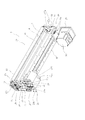
- FIG. 2 is a perspective view of the cleaning device 1 according to the embodiment as viewed from the lower front side
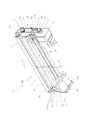
- FIG. 3 is a perspective view of the cleaning device 1 as viewed from the lower rear side
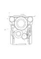
- 4 is a cross-sectional view taken along the line IV-IV in FIG.
- the cleaning device 1 is unitized as a unitary structure by a frame unit 10.
- the frame unit 10 connects the left and right side plate portions 11 and 12 having a rectangular shape that rotatably supports the cleaning roller 2, the brush rollers 3 ⁇ / b> A and 3 ⁇ / b> B, and the metal roller 4, and the four corners of these side plate portions 11 and 12.
- the upper angle members 13 and 14 and the lower angle members 15 and 16 are included.
- the side plate portions 11 and 12 are made of an insulating material (for example, a resin such as polyacetal), and the side plate portions 11 and 12 are each rotated by the cleaning roller 2, the brush rollers 3 ⁇ / b> A and 3 ⁇ / b> B, and the metal roller 4. Attachment holes for attaching the shaft are respectively formed at predetermined positions.
- an insulating material for example, a resin such as polyacetal
- Bearings 17a into which the rotation shafts of the cleaning roller 2, the brush rollers 3A and 3B, and the metal roller 4 are inserted are respectively incorporated in these mounting holes, and an electrode portion 17b is electrically connected to the outer ring portion of each of the bearings 17a. Built in contact with. Further, an insulating ring-shaped lid member 17c for fixing the bearing 17a so as not to be detached from the mounting hole is attached to the outer surface of each of the mounting holes.
- a charge applying mechanism is configured including the bearing 17a and the electrode portion 17b incorporated in each of the through holes.
- Pulleys 18 and 19 made of an insulator are attached to end portions of the rotation shafts of the brush rollers 3A and 3B inserted into the side plate portion 11, respectively.
- a pulley 20 made of an insulator is attached to the end of the rotating shaft of the metal roller 4 inserted into the side plate 12.
- one end side bottom surface of the lower angle members 15 and 16 one side of the mounting plate 21 having a substantially L-shape is fixed to the other side of the mounting plate 21, through the auxiliary plate 22, the brush driving motor 23A, 23B is attached.
- insertion holes 21 a through which the rotation shafts of the brush drive motors 23 ⁇ / b> A and 23 ⁇ / b> B are inserted are formed in the shape of a long hole in two places on the left and right sides.
- the attachment hole 21b is formed in the shape of a long hole on both sides of the insertion hole 21a.
- Pulleys 24 and 25 made of an insulator are mounted on the tip ends of the rotation shafts of the brush drive motors 23A and 23B inserted through the insertion holes 21a of the mounting plate 21, respectively.
- the pulley 18 of the brush roller 3A and the pulley 24 of the brush drive motor 23A are wound around the transmission belt 26.
- the pulley 19 of the brush roller 3B and the pulley 25 of the brush drive motor 23B are wound around the transmission belt 27. Yes.
- one side of the mounting plate 28 having a substantially L shape is fixed to the bottom surfaces of the other angle members 15 and 16, and a metal roller driving motor 30 is mounted on the other side of the mounting plate 28.
- the auxiliary plate 29 is attached with a fixing member (bolt) 42.
- a fixing member (bolt) 42 On the other side of the mounting plate 28, several mounting holes 28 a for fixing the auxiliary plate 29 with fixing members (bolts) 42 are formed on the left and right, and the fixing member 42 is inserted above the auxiliary plate 29. Insertion holes 29a for attachment are formed in a long hole shape at two places on the left and right.
- An insertion hole 29b through which the rotation shaft 30a of the metal roller drive motor 30 passes is formed near the substantially central portion of the auxiliary plate 29, and is insulated from the tip of the rotation shaft 30a of the metal roller drive motor 30 inserted through the insertion hole 29b.
- a pulley 31 formed of a body is attached.
- the pulley 20 of the metal roller 4 and the pulley 31 of the metal roller drive motor 30 are wound around the transmission belt 32, and the rotation speed of the metal roller 4 is set to a predetermined speed by controlling the drive of the metal roller drive motor 30. It is possible to set.
- the blade 5 is fixed to the blade mounting portion 33.
- a dust collecting unit (not shown) for collecting the dust separated by the blade 5 is attached to the lower side of the blade 5.
- the rotational speeds of the brush rollers 3A and 3B can be set and switched in three stages (predetermined values of low speed, medium speed, and high speed).
- the method of setting (shifting) the rotation speed of the brush rollers 3A and 3B is not limited to this form.
- the brush drive motor 23A is set so that the rotation speed of the brush roller 3A is high and the rotation speed of the brush roller 3B is low.
- 23B drive switching control is preferably configured to be interlocked with an operation (conveying direction switching operation) of a conveying conveyor (not shown) that conveys the object S to be cleaned.
- the cleaning roller 2 rotates in the follower direction (arrow ⁇ ′ direction) of the brush roller 3A. It becomes possible to perform cleaning while conveying the cleaning body S in the direction of the arrow ⁇ .
- the brush roller 3A is simultaneously rotated so that the rotation speed of the brush roller 3A becomes a medium speed.
- the drive switching control of the brush drive motors 23A and 23B is performed so that the rotation speed of 3B is also medium.
- the rotation speed of the brush roller 3A and the rotation speed of the brush roller 3B become the same speed, so that the rotation of the cleaning roller 2 can be stopped and the conveyance of the cleaning target S is temporarily interrupted. It becomes possible.
- the rotation speed of the brush roller 3B is high, while the rotation speed of the brush roller 3B is high.
- the drive switching control is also preferably configured so as to be interlocked with an operation (conveying direction switching operation) of a conveying conveyor (not shown) that conveys the object S to be cleaned.
- the rotation speed of the brush roller 3B becomes higher than the rotation speed of the brush roller 3A, so that the cleaning roller 2 rotates in the follower direction (arrow ⁇ ′ direction) of the brush roller 3B. It becomes possible to perform cleaning while transporting the cleaning body S in the direction of the arrow ⁇ .
- the cleaning device 1 since the brush rollers 3A and 3B are in contact with the cleaning roller 2, dust existing on the surface of the cleaning roller 2 is removed by the plurality of brush rollers 3A and 3B. As a result, the dust removal efficiency can be increased and the cleanliness of the surface of the cleaning roller 2 can be increased as compared with the conventional apparatus (see FIG. 8) provided with the transfer roller.
- the cleaning device 1 dust adsorbed by the electrostatic force on the surface of the cleaning roller 2 is scraped off by the brush rollers 3A and 3B, and the dust scraped off by the brush rollers 3A and 3B is removed by the electrostatic force. Since the dust adsorbed by the metal roller 4 and scraped by the metal roller 4 is scraped off from the metal roller 4 by the blade 5, the dust adsorbing operation by the cleaning roller 2 is stably maintained for a long time, and the transfer used in the past is used. By adopting a structure in which the roller is omitted, the cost of the apparatus can be reduced and the structure can be made compact.
- the plurality of brush rollers 3A, 3B are configured to rotate in opposite directions, and the rotation speed of the brush rollers 3A, 3B can be arbitrarily set.
- the cleaning roller 2 can be rotated not only in one direction but also in the reverse direction, and the object S to be cleaned is not only in one direction but also in the reverse direction. Can also be transported.
- the rotation speeds of the brush rollers 3A and 3B the same, the rotation of the cleaning roller 2 can be stopped, and a highly convenient apparatus that can cope with any conveyance direction can be obtained.
- the case where the two brush rollers 3A and 3B are used as the brush body that removes dust on the surface of the cleaning roller 2 has been described.
- a configuration in which three or more brush rollers are used may be employed.
- a multiple of two rollers (four, six, etc.) are arranged symmetrically with respect to the cleaning roller 2, and these brushes are divided into a plurality of brush roller groups on the right side and a plurality of brush roller groups on the left side.
- the roller groups By configuring the roller groups to rotate in opposite directions, the same control as described above can be performed.
- the two brush rollers 3A and 3B are disposed and are configured to rotate in opposite directions to each other, but the rotation direction of the cleaning roller 2 may be only one direction (that is, In the case where the conveyance direction of the cleaning target S is only one direction), the brush rollers 3A and 3B may be configured to rotate in the same direction.
- the brush roller may be constituted by one.
- the cleaning device 1A as shown in FIG. 5 The roller 3 rotates in the opposite direction to the cleaning roller 2 so that the brush roller 3 can efficiently scrape dust from the surface of the cleaning roller 2.
- the configuration of the cleaning device 1A as shown in FIG. 5 the cost of the device can be further reduced by simplifying the configuration of the device.
- a configuration in which three or more brush rollers are used may be employed.
- the case where the brush rollers 3A and 3B having substantially the same length as the cleaning roller 2 are used has been described.
- a plurality of brush rollers having a shorter length (for example, about half) than the cleaning roller 2 may be employed and disposed at positions shifted in the axial direction of the cleaning roller 2. According to this form, the cost of parts can be reduced by using a short brush roller, and the structure can be made compact.
- the cleaning device 1 is disposed below the cleaning target S, and the lower surface of the cleaning target S is cleaned.
- the cleaning device 1 is disposed below the cleaning target S, and the lower surface of the cleaning target S is cleaned.
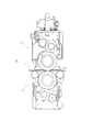
- the cleaning device 1A is disposed on the lower side of the object to be cleaned S
- the cleaning device 1B is disposed on the upper side
- the upper and lower surfaces of the object to be cleaned S are simultaneously cleaned. May be configured.
- the cleaning rollers 2 are disposed on the upper and lower surfaces of the upper surface of the object to be cleaned S and the lower surface of the object to be cleaned S, so that dust present on both the upper and lower surfaces of the object to be cleaned S can be simultaneously removed with a single operation. Therefore, it is possible to provide the cleaning device 1C with extremely high work efficiency.
- the cleaning roller 2 When the cleaning device is disposed on the upper side of the object to be cleaned S like the cleaning device 1B, the cleaning roller 2 is provided so that the upper surface can be appropriately pressed according to the shape of the surface of the object to be cleaned S. It is preferable to have a configuration that can swing up and down.
- the frame unit 10 as a whole can swing up and down, or a rotation support mechanism (not shown) that allows the cleaning roller 2 to swing along an arc is separately provided in the frame unit 10.
- a configuration in which the cleaning roller 2 is rotated (swinged) in the vertical direction around the rotation shaft of the support mechanism may be employed.
- the mounting position of the blade 5 is not limited to the position shown in FIG. 4, and is arranged at a position suitable for scraping dust from the metal roller 4 in consideration of the structure of the frame unit 10 and the like. It is desirable to do.
- a cleaning device that removes dust from a substrate that is often used for mounting a semiconductor device such as a glass substrate, a printed circuit board, a film, a sheet, or a plastic plate, and can be widely used in the field of semiconductor devices.
Landscapes
- Engineering & Computer Science (AREA)
- Manufacturing & Machinery (AREA)
- Microelectronics & Electronic Packaging (AREA)
- Cleaning In General (AREA)
Description
ここで、前記ブラシ体が複数個装備されている形態とは、前記クリーニングローラと略同じ長さの前記ブラシ体が複数個装備されている形態だけでなく、前記クリーニングローラよりも短い(例えば、半分程度の)長さの複数の前記ブラシ体が、前記クリーニングローラの軸方向にずらされた位置に配設された形態なども含まれる。
例えば、複数のブラシ体が互いに同一方向に回転するように構成した場合、各ブラシ体の連れ回り方向に前記クリーニングローラを容易に回転させることが可能となる。一方、各ブラシ体が互いに逆方向に回転するように構成した場合、例えば、2本のブラシ体、各々の回転速度を同じ速度に設定すれば、前記クリーニングローラの回転を停止させる制御が可能となり、各ブラシ体の回転速度を異なる速度に設定することで、前記クリーニングローラを所望の方向へ回転させる制御も可能となる。
逆に、一方のブラシ体の回転速度が高速、他方のブラシ体の回転速度が低速に設定されると、前記クリーニングローラが一方のブラシ体の連れ回り方向に回転するように制御される。このように、被クリーニング体の搬送方向を、適宜切り換えることが可能となり、双方向の搬送が必要な搬送システムに対応させることができ、利便性の高い装置とすることができる。
また、ブラシローラ3Aとブラシローラ3Bとの回転速度を同じ速度に設定して、クリーニングローラ2の回転を停止させる制御も可能となっている。
例えば、2の倍数のローラ(4本、6本など)をクリーニングローラ2に対して左右対称に配設し、右側の複数のブラシローラ群と、左側の複数のブラシローラ群とで、これらブラシローラ群を互いに逆方向に回転するように構成することで、上記と同様な制御を行うことができる。この場合は、左右のブラシローラ群に対応する金属ローラを適宜配設(増設)することが好ましい。
また、逆にブラシローラを3本以上使用した構成とすることもできる。
1A,1B,1C クリーニング装置
2 クリーニングローラ
3A、3B ブラシローラ
3 ブラシローラ
4 金属ローラ
5 ブレード
10 フレームユニット
11、12 側板部
13、14 上側アングル部材
15、16 下側アングル部材
23A、23B ブラシ駆動モータ
30 金属ローラ駆動モータ
S 被クリーニング体
S1 表面
Claims (9)
- 被クリーニング体表面に存在する塵埃を静電気力を利用して除去するクリーニング装置であって、
前記被クリーニング体表面に接触させるクリーニングローラと、
該クリーニングローラに接触して該クリーニングローラ表面の塵埃を除去するブラシ体とを備えていることを特徴とするクリーニング装置。 - さらに、前記ブラシ体に接触して該ブラシ体から塵埃を受取る金属ローラと、
該金属ローラに付着した塵埃を除去するブレード体と、
前記クリーニングローラ、前記ブラシ体、及び前記金属ローラに電荷を付与する電荷付与機構とを備えていることを特徴とする請求項1記載のクリーニング装置。 - 前記ブラシ体が複数個装備されていることを特徴とする請求項1又は請求項2記載のクリーニング装置。
- 複数個の前記ブラシ体が互いに逆方向に回転するように構成されていることを特徴とする請求項3記載のクリーニング装置。
- 複数個の前記ブラシ体が同方向に回転するように構成されていることを特徴とする請求項3記載のクリーニング装置。
- 前記ブラシ体の回転速度が任意に設定可能となっていることを特徴とする請求項1又は2記載のクリーニング装置。
- 前記ブラシ体が単数個装備されていることを特徴とする請求項1又は請求項2記載のクリーニング装置。
- 前記ブラシ体の回転速度が任意に設定可能となっていることを特徴とする請求項7記載のクリーニング装置。
- 上記クリーニング装置(1)~(8)のいずれか2つの装置を用い、前記被クリーニング体表面に接触して塵埃を除去するクリーニングローラが、前記被クリーニング体上面側及び前記被クリーニング体下面側の上下両面側に配置されていることを特徴とするクリーニング装置。
Priority Applications (4)
| Application Number | Priority Date | Filing Date | Title |
|---|---|---|---|
| KR1020147035162A KR101718199B1 (ko) | 2012-06-06 | 2013-05-27 | 청소장치 |
| JP2014519822A JP6124885B2 (ja) | 2012-06-06 | 2013-05-27 | クリーニング装置 |
| CN201380027542.1A CN104334290B (zh) | 2012-06-06 | 2013-05-27 | 洁净装置 |
| IN2505MUN2014 IN2014MN02505A (ja) | 2012-06-06 | 2014-12-09 |
Applications Claiming Priority (2)
| Application Number | Priority Date | Filing Date | Title |
|---|---|---|---|
| JP2012-129341 | 2012-06-06 | ||
| JP2012129341 | 2012-06-06 |
Publications (1)
| Publication Number | Publication Date |
|---|---|
| WO2013183248A1 true WO2013183248A1 (ja) | 2013-12-12 |
Family
ID=49711656
Family Applications (1)
| Application Number | Title | Priority Date | Filing Date |
|---|---|---|---|
| PCT/JP2013/003343 Ceased WO2013183248A1 (ja) | 2012-06-06 | 2013-05-27 | クリーニング装置 |
Country Status (6)
| Country | Link |
|---|---|
| JP (1) | JP6124885B2 (ja) |
| KR (1) | KR101718199B1 (ja) |
| CN (1) | CN104334290B (ja) |
| IN (1) | IN2014MN02505A (ja) |
| TW (1) | TWI546132B (ja) |
| WO (1) | WO2013183248A1 (ja) |
Cited By (11)
| Publication number | Priority date | Publication date | Assignee | Title |
|---|---|---|---|---|
| WO2015108003A1 (ja) * | 2014-01-20 | 2015-07-23 | バンドー化学株式会社 | クリーニング装置 |
| JP2015178091A (ja) * | 2014-02-25 | 2015-10-08 | バンドー化学株式会社 | クリーニング装置、粘着ローラユニット及び粘着ローラ |
| CN106166553A (zh) * | 2015-05-22 | 2016-11-30 | 阪东化学株式会社 | 清洁装置 |
| JP2017104868A (ja) * | 2017-03-14 | 2017-06-15 | バンドー化学株式会社 | クリーニング装置 |
| JP2019051517A (ja) * | 2018-12-04 | 2019-04-04 | バンドー化学株式会社 | クリーニング装置 |
| KR102016268B1 (ko) * | 2018-12-06 | 2019-08-28 | 정진욱 | 미세먼지 포집 장치 |
| JP2020037110A (ja) * | 2018-12-04 | 2020-03-12 | バンドー化学株式会社 | クリーニング装置 |
| KR102118144B1 (ko) * | 2020-01-06 | 2020-06-02 | 함창석 | 이물질 제거 능력이 개선된 식품 포장비닐용 제대기 |
| CN112431001A (zh) * | 2020-11-04 | 2021-03-02 | 南通金鹏玻纤制品有限公司 | 一种玻纤布表面毛丝清除装置及其工作方法 |
| CN112893322A (zh) * | 2021-01-19 | 2021-06-04 | 江苏亚宝绝缘材料股份有限公司 | 一种聚酰亚胺薄膜的生产设备 |
| CN114101131A (zh) * | 2021-11-22 | 2022-03-01 | 南通宝鹏健身器材科技有限公司 | 一种pu杠铃片内层板材清洁处理装置 |
Families Citing this family (14)
| Publication number | Priority date | Publication date | Assignee | Title |
|---|---|---|---|---|
| KR102454775B1 (ko) | 2015-02-18 | 2022-10-17 | 가부시키가이샤 에바라 세이사꾸쇼 | 기판 세정 장치, 기판 세정 방법 및 기판 처리 장치 |
| CN104967045B (zh) * | 2015-06-02 | 2018-07-31 | 国家电网公司 | 带电拆除异物专用操作头 |
| CN109201547A (zh) * | 2017-06-30 | 2019-01-15 | 中电海康集团有限公司 | 晶圆清洗装置 |
| CN107537800B (zh) * | 2017-09-04 | 2020-06-16 | 东莞市沃顿印刷有限公司 | 一种新型原材料除尘机 |
| CN107838072A (zh) * | 2017-10-30 | 2018-03-27 | 国网福建省电力有限公司 | 瓷瓶表面自动清洗机 |
| CN107962011A (zh) * | 2017-12-20 | 2018-04-27 | 东莞市锐祥智能卡科技有限公司 | 一种sim卡双芯片槽清洁装置 |
| CN108015035A (zh) * | 2018-01-04 | 2018-05-11 | 苏州统硕科技有限公司 | 自动化板清机 |
| CN108529291A (zh) * | 2018-04-20 | 2018-09-14 | 张吉超 | 一种纺织用布匹除杂装置 |
| CN108606731B (zh) * | 2018-06-08 | 2021-04-09 | 安徽风向标清洁设备有限公司 | 用于扫地机的刷毛机构 |
| CN108940939A (zh) * | 2018-06-14 | 2018-12-07 | 东莞市光纳光电科技有限公司 | 一种具备自清洁能力的指纹识别屏 |
| CN108745980B (zh) * | 2018-07-03 | 2021-04-06 | 佛山市佳世达薄膜科技有限公司 | 一种薄膜分卷装置 |
| JP7161418B2 (ja) | 2019-01-30 | 2022-10-26 | 株式会社荏原製作所 | 基板洗浄装置、基板処理装置、洗浄部材のセルフクリーニング方法 |
| CN115318757B (zh) * | 2022-07-11 | 2023-08-18 | 星源电子科技(深圳)有限公司 | 一种清洁效果好的气动滚轮粘尘治具 |
| CN115446028B (zh) * | 2022-08-26 | 2023-04-14 | 南通鑫科智能科技有限公司 | 一种锂电池半成品检验设备 |
Citations (4)
| Publication number | Priority date | Publication date | Assignee | Title |
|---|---|---|---|---|
| JPS55119197U (ja) * | 1979-02-17 | 1980-08-23 | ||
| JPS5646015U (ja) * | 1979-09-13 | 1981-04-24 | ||
| JP2002244522A (ja) * | 2001-02-21 | 2002-08-30 | Ricoh Co Ltd | 放電生成物除去方法及び画像形成装置 |
| WO2010109755A1 (ja) * | 2009-03-23 | 2010-09-30 | バンドー化学株式会社 | クリーニングシステム |
Family Cites Families (10)
| Publication number | Priority date | Publication date | Assignee | Title |
|---|---|---|---|---|
| JPS5248320B2 (ja) | 1972-02-16 | 1977-12-08 | ||
| JPS6468206A (en) * | 1987-09-10 | 1989-03-14 | Shishido Seidenki Kk | Duster |
| JPH08203851A (ja) * | 1995-01-27 | 1996-08-09 | Sony Corp | 清浄化装置 |
| JPH09267945A (ja) * | 1996-03-29 | 1997-10-14 | Tec Corp | 画像形成装置 |
| JP2003005599A (ja) * | 2001-06-18 | 2003-01-08 | Ricoh Co Ltd | クリーニング装置、プロセスカートリッジ、および画像形成装置 |
| JP2003225625A (ja) * | 2002-02-05 | 2003-08-12 | Reyoon Kogyo:Kk | 基板又はシート等の除塵方法とその方法を使用した基板又はシート等の除塵装置 |
| JP2005218923A (ja) * | 2004-02-04 | 2005-08-18 | Nagaoka Seisakusho:Kk | 基板塵埃除去装置 |
| JP2006251492A (ja) * | 2005-03-11 | 2006-09-21 | Murata Mach Ltd | クリーニング装置 |
| CN201098690Y (zh) * | 2007-10-31 | 2008-08-13 | 南通中利机电制造厂 | 金属膜清除导电轮装置 |
| JP5491017B2 (ja) | 2008-10-22 | 2014-05-14 | バンドー化学株式会社 | クリーニングシステム |
-
2013
- 2013-05-27 JP JP2014519822A patent/JP6124885B2/ja active Active
- 2013-05-27 KR KR1020147035162A patent/KR101718199B1/ko active Active
- 2013-05-27 WO PCT/JP2013/003343 patent/WO2013183248A1/ja not_active Ceased
- 2013-05-27 CN CN201380027542.1A patent/CN104334290B/zh active Active
- 2013-05-29 TW TW102118917A patent/TWI546132B/zh active
-
2014
- 2014-12-09 IN IN2505MUN2014 patent/IN2014MN02505A/en unknown
Patent Citations (4)
| Publication number | Priority date | Publication date | Assignee | Title |
|---|---|---|---|---|
| JPS55119197U (ja) * | 1979-02-17 | 1980-08-23 | ||
| JPS5646015U (ja) * | 1979-09-13 | 1981-04-24 | ||
| JP2002244522A (ja) * | 2001-02-21 | 2002-08-30 | Ricoh Co Ltd | 放電生成物除去方法及び画像形成装置 |
| WO2010109755A1 (ja) * | 2009-03-23 | 2010-09-30 | バンドー化学株式会社 | クリーニングシステム |
Cited By (15)
| Publication number | Priority date | Publication date | Assignee | Title |
|---|---|---|---|---|
| JP2015135456A (ja) * | 2014-01-20 | 2015-07-27 | バンドー化学株式会社 | クリーニング装置 |
| WO2015108003A1 (ja) * | 2014-01-20 | 2015-07-23 | バンドー化学株式会社 | クリーニング装置 |
| JP2018187634A (ja) * | 2014-02-25 | 2018-11-29 | バンドー化学株式会社 | クリーニング装置 |
| JP2015178091A (ja) * | 2014-02-25 | 2015-10-08 | バンドー化学株式会社 | クリーニング装置、粘着ローラユニット及び粘着ローラ |
| CN106166553A (zh) * | 2015-05-22 | 2016-11-30 | 阪东化学株式会社 | 清洁装置 |
| JP2016215155A (ja) * | 2015-05-22 | 2016-12-22 | バンドー化学株式会社 | クリーニング装置 |
| JP2017104868A (ja) * | 2017-03-14 | 2017-06-15 | バンドー化学株式会社 | クリーニング装置 |
| JP2019051517A (ja) * | 2018-12-04 | 2019-04-04 | バンドー化学株式会社 | クリーニング装置 |
| JP2020037110A (ja) * | 2018-12-04 | 2020-03-12 | バンドー化学株式会社 | クリーニング装置 |
| KR102016268B1 (ko) * | 2018-12-06 | 2019-08-28 | 정진욱 | 미세먼지 포집 장치 |
| KR102118144B1 (ko) * | 2020-01-06 | 2020-06-02 | 함창석 | 이물질 제거 능력이 개선된 식품 포장비닐용 제대기 |
| CN112431001A (zh) * | 2020-11-04 | 2021-03-02 | 南通金鹏玻纤制品有限公司 | 一种玻纤布表面毛丝清除装置及其工作方法 |
| CN112893322A (zh) * | 2021-01-19 | 2021-06-04 | 江苏亚宝绝缘材料股份有限公司 | 一种聚酰亚胺薄膜的生产设备 |
| CN114101131A (zh) * | 2021-11-22 | 2022-03-01 | 南通宝鹏健身器材科技有限公司 | 一种pu杠铃片内层板材清洁处理装置 |
| CN114101131B (zh) * | 2021-11-22 | 2022-09-02 | 南通宝鹏健身器材科技有限公司 | 一种pu杠铃片内层板材清洁处理装置 |
Also Published As
| Publication number | Publication date |
|---|---|
| KR101718199B1 (ko) | 2017-03-20 |
| TWI546132B (zh) | 2016-08-21 |
| CN104334290B (zh) | 2016-11-09 |
| JPWO2013183248A1 (ja) | 2016-01-28 |
| IN2014MN02505A (ja) | 2015-07-17 |
| TW201404489A (zh) | 2014-02-01 |
| JP6124885B2 (ja) | 2017-05-10 |
| KR20150013303A (ko) | 2015-02-04 |
| CN104334290A (zh) | 2015-02-04 |
Similar Documents
| Publication | Publication Date | Title |
|---|---|---|
| JP6124885B2 (ja) | クリーニング装置 | |
| TW201532689A (zh) | 清潔裝置 | |
| JP6617180B2 (ja) | クリーニング装置 | |
| WO2015108003A1 (ja) | クリーニング装置 | |
| JP5015365B2 (ja) | クリーニングシステム | |
| TWI408012B (zh) | Clean device | |
| CN101356017B (zh) | 灰尘除去装置 | |
| US8083226B2 (en) | Sheet guiding apparatus with an electric field or charge inverting portion | |
| EP2846937B1 (en) | Device and method for removal of particles from a web of material | |
| US10081497B2 (en) | Solenoid-powered conveying device | |
| WO2018123076A1 (ja) | 無限軌道およびそれを備えた壁面吸着走行装置 | |
| CN103347621B (zh) | 洁净装置 | |
| KR101416593B1 (ko) | 롤러의 처짐 방지를 위한 기판 이송 장치 | |
| CN116174405B (zh) | 一种激光清洗设备、激光清洗方法和极片制造系统 | |
| JP7671930B1 (ja) | クリーニング装置 | |
| KR200338594Y1 (ko) | 상압 플라즈마를 이용한 기판세정 공정용 이송장치 | |
| CN205574994U (zh) | 一种烟叶输送带清洁装置 | |
| US20100196060A1 (en) | Developer unit for an electrophotographic printing device for printing on glass or ceramic material | |
| KR101108889B1 (ko) | 사무기기부품용 롤러샤프트를 세척하는 장치 | |
| KR100723781B1 (ko) | 판형 세정대상물 세정장치 | |
| WO2025115676A1 (ja) | クリーニング装置 | |
| CN119098445A (zh) | 一种基于静电吸附原理的电子线路板表面清洁装置 | |
| JP2005049677A (ja) | トナー搬送機構 | |
| JPH10254224A (ja) | 非接触帯電装置 | |
| CN120717170A (zh) | 带式输送机用振动胶带清扫刷装置 |
Legal Events
| Date | Code | Title | Description |
|---|---|---|---|
| 121 | Ep: the epo has been informed by wipo that ep was designated in this application |
Ref document number: 13801361 Country of ref document: EP Kind code of ref document: A1 |
|
| ENP | Entry into the national phase |
Ref document number: 2014519822 Country of ref document: JP Kind code of ref document: A |
|
| NENP | Non-entry into the national phase |
Ref country code: DE |
|
| ENP | Entry into the national phase |
Ref document number: 20147035162 Country of ref document: KR Kind code of ref document: A |
|
| 122 | Ep: pct application non-entry in european phase |
Ref document number: 13801361 Country of ref document: EP Kind code of ref document: A1 |