WO2013175996A1 - マイクロチップへの試薬供給方法及びマイクロチップ並びにマイクロチップへの試薬供給装置 - Google Patents
マイクロチップへの試薬供給方法及びマイクロチップ並びにマイクロチップへの試薬供給装置 Download PDFInfo
- Publication number
- WO2013175996A1 WO2013175996A1 PCT/JP2013/063362 JP2013063362W WO2013175996A1 WO 2013175996 A1 WO2013175996 A1 WO 2013175996A1 JP 2013063362 W JP2013063362 W JP 2013063362W WO 2013175996 A1 WO2013175996 A1 WO 2013175996A1
- Authority
- WO
- WIPO (PCT)
- Prior art keywords
- reagent
- microchip
- flow path
- fluid
- recovery means
- Prior art date
- Legal status (The legal status is an assumption and is not a legal conclusion. Google has not performed a legal analysis and makes no representation as to the accuracy of the status listed.)
- Ceased
Links
Images


Classifications
-
- G—PHYSICS
- G01—MEASURING; TESTING
- G01N—INVESTIGATING OR ANALYSING MATERIALS BY DETERMINING THEIR CHEMICAL OR PHYSICAL PROPERTIES
- G01N35/00—Automatic analysis not limited to methods or materials provided for in any single one of groups G01N1/00 - G01N33/00; Handling materials therefor
- G01N35/10—Devices for transferring samples or any liquids to, in, or from, the analysis apparatus, e.g. suction devices, injection devices
- G01N35/1095—Devices for transferring samples or any liquids to, in, or from, the analysis apparatus, e.g. suction devices, injection devices for supplying the samples to flow-through analysers
-
- B—PERFORMING OPERATIONS; TRANSPORTING
- B01—PHYSICAL OR CHEMICAL PROCESSES OR APPARATUS IN GENERAL
- B01L—CHEMICAL OR PHYSICAL LABORATORY APPARATUS FOR GENERAL USE
- B01L3/00—Containers or dishes for laboratory use, e.g. laboratory glassware; Droppers
- B01L3/50—Containers for the purpose of retaining a material to be analysed, e.g. test tubes
- B01L3/502—Containers for the purpose of retaining a material to be analysed, e.g. test tubes with fluid transport, e.g. in multi-compartment structures
- B01L3/5027—Containers for the purpose of retaining a material to be analysed, e.g. test tubes with fluid transport, e.g. in multi-compartment structures by integrated microfluidic structures, i.e. dimensions of channels and chambers are such that surface tension forces are important, e.g. lab-on-a-chip
- B01L3/502715—Containers for the purpose of retaining a material to be analysed, e.g. test tubes with fluid transport, e.g. in multi-compartment structures by integrated microfluidic structures, i.e. dimensions of channels and chambers are such that surface tension forces are important, e.g. lab-on-a-chip characterised by interfacing components, e.g. fluidic, electrical, optical or mechanical interfaces
-
- G—PHYSICS
- G01—MEASURING; TESTING
- G01N—INVESTIGATING OR ANALYSING MATERIALS BY DETERMINING THEIR CHEMICAL OR PHYSICAL PROPERTIES
- G01N33/00—Investigating or analysing materials by specific methods not covered by groups G01N1/00 - G01N31/00
- G01N33/48—Biological material, e.g. blood, urine; Haemocytometers
- G01N33/50—Chemical analysis of biological material, e.g. blood, urine; Testing involving biospecific ligand binding methods; Immunological testing
- G01N33/53—Immunoassay; Biospecific binding assay; Materials therefor
- G01N33/531—Production of immunochemical test materials
-
- B—PERFORMING OPERATIONS; TRANSPORTING
- B01—PHYSICAL OR CHEMICAL PROCESSES OR APPARATUS IN GENERAL
- B01L—CHEMICAL OR PHYSICAL LABORATORY APPARATUS FOR GENERAL USE
- B01L2200/00—Solutions for specific problems relating to chemical or physical laboratory apparatus
- B01L2200/02—Adapting objects or devices to another
- B01L2200/026—Fluid interfacing between devices or objects, e.g. connectors, inlet details
- B01L2200/027—Fluid interfacing between devices or objects, e.g. connectors, inlet details for microfluidic devices
-
- B—PERFORMING OPERATIONS; TRANSPORTING
- B01—PHYSICAL OR CHEMICAL PROCESSES OR APPARATUS IN GENERAL
- B01L—CHEMICAL OR PHYSICAL LABORATORY APPARATUS FOR GENERAL USE
- B01L2200/00—Solutions for specific problems relating to chemical or physical laboratory apparatus
- B01L2200/06—Fluid handling related problems
- B01L2200/0689—Sealing
-
- B—PERFORMING OPERATIONS; TRANSPORTING
- B01—PHYSICAL OR CHEMICAL PROCESSES OR APPARATUS IN GENERAL
- B01L—CHEMICAL OR PHYSICAL LABORATORY APPARATUS FOR GENERAL USE
- B01L2200/00—Solutions for specific problems relating to chemical or physical laboratory apparatus
- B01L2200/16—Reagents, handling or storing thereof
-
- B—PERFORMING OPERATIONS; TRANSPORTING
- B01—PHYSICAL OR CHEMICAL PROCESSES OR APPARATUS IN GENERAL
- B01L—CHEMICAL OR PHYSICAL LABORATORY APPARATUS FOR GENERAL USE
- B01L2300/00—Additional constructional details
- B01L2300/04—Closures and closing means
- B01L2300/041—Connecting closures to device or container
- B01L2300/044—Connecting closures to device or container pierceable, e.g. films, membranes
-
- B—PERFORMING OPERATIONS; TRANSPORTING
- B01—PHYSICAL OR CHEMICAL PROCESSES OR APPARATUS IN GENERAL
- B01L—CHEMICAL OR PHYSICAL LABORATORY APPARATUS FOR GENERAL USE
- B01L2300/00—Additional constructional details
- B01L2300/06—Auxiliary integrated devices, integrated components
- B01L2300/0627—Sensor or part of a sensor is integrated
- B01L2300/0636—Integrated biosensor, microarrays
-
- B—PERFORMING OPERATIONS; TRANSPORTING
- B01—PHYSICAL OR CHEMICAL PROCESSES OR APPARATUS IN GENERAL
- B01L—CHEMICAL OR PHYSICAL LABORATORY APPARATUS FOR GENERAL USE
- B01L2300/00—Additional constructional details
- B01L2300/08—Geometry, shape and general structure
- B01L2300/0809—Geometry, shape and general structure rectangular shaped
- B01L2300/0816—Cards, e.g. flat sample carriers usually with flow in two horizontal directions
-
- B—PERFORMING OPERATIONS; TRANSPORTING
- B01—PHYSICAL OR CHEMICAL PROCESSES OR APPARATUS IN GENERAL
- B01L—CHEMICAL OR PHYSICAL LABORATORY APPARATUS FOR GENERAL USE
- B01L2300/00—Additional constructional details
- B01L2300/08—Geometry, shape and general structure
- B01L2300/0809—Geometry, shape and general structure rectangular shaped
- B01L2300/0819—Microarrays; Biochips
-
- B—PERFORMING OPERATIONS; TRANSPORTING
- B01—PHYSICAL OR CHEMICAL PROCESSES OR APPARATUS IN GENERAL
- B01L—CHEMICAL OR PHYSICAL LABORATORY APPARATUS FOR GENERAL USE
- B01L2300/00—Additional constructional details
- B01L2300/08—Geometry, shape and general structure
- B01L2300/0861—Configuration of multiple channels and/or chambers in a single devices
- B01L2300/0877—Flow chambers
-
- B—PERFORMING OPERATIONS; TRANSPORTING
- B01—PHYSICAL OR CHEMICAL PROCESSES OR APPARATUS IN GENERAL
- B01L—CHEMICAL OR PHYSICAL LABORATORY APPARATUS FOR GENERAL USE
- B01L2400/00—Moving or stopping fluids
- B01L2400/04—Moving fluids with specific forces or mechanical means
- B01L2400/0475—Moving fluids with specific forces or mechanical means specific mechanical means and fluid pressure
- B01L2400/0487—Moving fluids with specific forces or mechanical means specific mechanical means and fluid pressure fluid pressure, pneumatics
-
- B—PERFORMING OPERATIONS; TRANSPORTING
- B01—PHYSICAL OR CHEMICAL PROCESSES OR APPARATUS IN GENERAL
- B01L—CHEMICAL OR PHYSICAL LABORATORY APPARATUS FOR GENERAL USE
- B01L2400/00—Moving or stopping fluids
- B01L2400/06—Valves, specific forms thereof
- B01L2400/0677—Valves, specific forms thereof phase change valves; Meltable, freezing, dissolvable plugs; Destructible barriers
- B01L2400/0683—Valves, specific forms thereof phase change valves; Meltable, freezing, dissolvable plugs; Destructible barriers mechanically breaking a wall or membrane within a channel or chamber
-
- Y—GENERAL TAGGING OF NEW TECHNOLOGICAL DEVELOPMENTS; GENERAL TAGGING OF CROSS-SECTIONAL TECHNOLOGIES SPANNING OVER SEVERAL SECTIONS OF THE IPC; TECHNICAL SUBJECTS COVERED BY FORMER USPC CROSS-REFERENCE ART COLLECTIONS [XRACs] AND DIGESTS
- Y10—TECHNICAL SUBJECTS COVERED BY FORMER USPC
- Y10T—TECHNICAL SUBJECTS COVERED BY FORMER US CLASSIFICATION
- Y10T436/00—Chemistry: analytical and immunological testing
- Y10T436/25—Chemistry: analytical and immunological testing including sample preparation
- Y10T436/2575—Volumetric liquid transfer
Definitions
- the present invention relates to a reagent supply method to a microchip used for separation, synthesis, extraction, analysis, etc. of a trace amount of reagent, a microchip to which the method is applied, and a reagent supply for supplying a reagent to the microchip Relates to the device.
- microchips in which microscale analysis channels are formed on a small substrate made of, for example, silicon, silicone, glass, etc. Analysis has been carried out (for example, see Patent Document 1 and Patent Document 2 for the microchip and its manufacture).
- a microchip a chip suitable for various applications can be configured by providing regions having various functions such as a reaction region in which a reagent is arranged in a flow path also called a microchannel.
- Typical applications of microchips include chemical analysis such as genetic analysis, clinical diagnosis, and drug screening, biochemistry, pharmacy, medicine, veterinary analysis, compound synthesis, and environmental measurement.
- the above-described microchip typically has a structure in which a pair of substrates are bonded to face each other, and a fine channel (for example, a width of 10 to several hundred ⁇ m and a depth of 10 to 10 ⁇ m is formed on the surface of at least one of the substrates. About several hundred ⁇ m).
- a glass substrate is mainly used for a microchip because it can be easily manufactured and optically detected.
- development of a microchip using a resin substrate which is light in weight but is less likely to be damaged than a glass substrate and inexpensive.
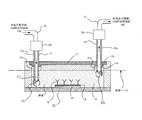
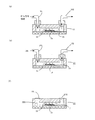
- FIG. 9A is a schematic diagram of the microchip 10.
- FIG. 9B is a cross-sectional view taken along the line AA in FIG. As shown in FIG.
- the microchip 10 has a structure in which a pair of substrates (a first microchip substrate 11 and a second microchip substrate 12) are bonded to face each other.
- a fine flow path 14 having an inflow port 13a and an exhaust port 13b, for example, having a width of about 10 to several hundred ⁇ m and a depth of about 10 to several hundred ⁇ m is formed.
- the flow path 14 is configured by the fine groove formed in the first microchip substrate 11 and the surface of the second microchip substrate 12.
- a metal thin film 15 is installed in the flow path.
- the metal thin film 15 is provided on the surface of the second microchip substrate 12 in the flow path (that is, the bonding surface of the first and second microchip substrates 11 and 12).
- the metal thin film 15 has a structure in which a gold (Au) thin film is laminated on a chromium (Cr) thin film.
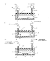
- the antibody is immobilized in the channel 14 of the microchip as follows. As shown in FIG. 10A, the reagent solution injection tube 101 is set in the inlet 13 a of the microchip 10. Similarly, a reagent solution discharge tube 102 is set in the discharge port 13 b of the microchip 10. Joints 103 are provided at the tips of the reagent solution injection tube 101 and the reagent solution discharge tube 102, and each joint 103 is connected to the inlet 13a and the outlet 13b.
- a phosphate buffered saline (Phosphate buffered saline, hereinafter referred to as PBS) is injected into the channel 14 of the microchip 10 from the reagent solution injection tube 101, and the channel 14 is washed.
- PBS phosphate buffered saline
- the PBS that has passed through the flow path 14 is discharged to the outside through the reagent solution discharge pipe 102 connected to the discharge port 13 b of the flow path 14.
- a SAM-forming liquid for example, an alkanethiol-containing solution
- a SAM-forming liquid for example, an alkanethiol-containing solution
- the alkanethiol in the alkanethiol-containing solution reacts with the Au thin film, and a self-assembled film (Self-Assembled Monolayer: SAM film 16) is formed on the Au thin film.
- the alkanethiol-containing solution that has not contributed to the SAM film formation is discharged to the outside through the reagent solution discharge tube 102.
- PBS is injected from the reagent solution injection tube 101 into the channel 14 of the microchip 10, and the alkanethiol-containing solution remaining in the channel 14 is removed.
- the PBS that has passed through the flow path 14 is discharged to the outside through the reagent solution discharge pipe 102.
- the antibody-containing solution is injected from the reagent solution injection tube 101 into the channel 14 of the microchip 10.
- the antibody in the antibody-containing solution reacts with the alkanethiol SAM film 16 and chemically binds thereto, and is immobilized on the SAM film 16. That is, antibody Ig is immobilized on the metal thin film 15.
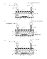
- FIG. 11 (d) since an antibody not fixed on the surface of the antibody Ig fixed to the SAM film 16 remains, or an antibody remains in a region other than the SAM film 16 in the flow path 14, FIG.
- PBS is injected into the flow path 14 of the microchip 10 from the reagent solution injection tube 101, and such residual antibodies are purged with PBS.
- the PBS containing the residual antibody is discharged to the outside through the reagent solution discharge tube 102 connected to the discharge port 13b of the flow path 14.
- the flow path 14 after the purge of the residual antibody with PBS is filled with PBS as shown in FIG. 11 (f), and the inlet 13a and outlet 13b of the microchip 10 are Sealed with a sealing material 104 such as a paraffin film.
- JP 2006-187730 A Japanese Patent No. 3714338
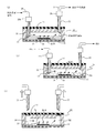
- the shape of the flow path near the inlet 13a and the outlet 13b of the microchip 10 is often a right-angled shape.
- the antibody-containing solution flowing through the channel 14 becomes turbulent. Due to the influence of this turbulent flow, as shown in FIG. 12, the contact between the antibody in the antibody-containing solution and the alkanethiol SAM film 16 is disturbed, and the reaction between the antibody and the SAM film 16 is inhibited. It becomes difficult to fix the antibody.
- the reagent solution injection tube 101 and the reagent solution discharge tube 102 are detached from the flow path 14 of the microchip 10, the reagent solution injection tube 101 and the reagent solution are connected from the inlet 13a and the discharge port 13b. If the joint 103 provided at the tip of the discharge pipe 102 is removed, bubbles are likely to be generated at the inlet 13a and the outlet 13b.
- a sealing material 104 such as a paraffin film sealing the inlet 13a and the outlet 13b of the microchip 10 is provided prior to distributing the reagent containing the antigen to the antibody immobilized in the flow path 14. Also during removal, as shown in FIG. 14, bubbles are likely to be generated at the inlet 13a and the outlet 13b. Further, when the reagent solution injection tube 101 and the reagent solution discharge tube 102 are attached to the microchip flow channel 14 in order to distribute the reagent containing the antigen in the flow channel 14, the reagent solution injection tube is supplied from the inlet 13 a and the discharge port 13 b. 101, even when a joint provided at the tip of the reagent solution discharge pipe 102 is connected, bubbles are likely to be generated at the inlet 13a and the outlet 13b.
- the inlet 13 a and the discharge port 13 b of the flow channel 14 When the sealing material 104 is removed, bubbles are likely to be generated in the flow path 14, and if the antibody is fixed in the flow path 14, the antibody is deactivated.
- the present invention has been made in view of the above circumstances, and an object of the present invention is to provide a microchip having a reagent arrangement area for immobilizing an anaerobic antibody, with the reagent arrangement area almost in contact with air, and An object of the present invention is to provide a reagent supplying method to a microchip capable of supplying an anaerobic reagent such as an anaerobic antibody stably without variation and a microchip to which the method is applied. Another object of the present invention is to provide a reagent supply device to a microchip capable of supplying an anaerobic reagent such as an anaerobic antibody to the reagent arrangement region of the microchip with almost no contact with air.
- the flow inlet and the discharge port are self-adjusted.
- a silicone gel provided at the inflow port and the discharge port includes a fluid discharge unit having a tip formed in a needle shape and having an opening serving as a fluid discharge port, and a fluid recovery unit having the same shape as the fluid discharge unit.
- a reagent such as anaerobic antibody is supplied to the flow path that is the reagent arrangement area from the opening of the fluid discharge means.
- the supplied reagent was recovered from the opening of the fluid reforming means.
- a reagent such as an anaerobic antibody can be supplied to the reagent placement region and the reagent can be recovered from the region with almost no contact with air.
- silicone gel is difficult to mold with a mold, as will be described later, for example, a recess (step) is formed around the inlet and outlet, and the silicone gel is poured into this recess (step). The inlet and outlet may be closed.
- the reagent supply device for supplying the reagent to the microchip includes the fluid discharge means, the fluid recovery means, and the fluid discharge means and the fluid recovery means that are arranged through the silicone gel having the self-repairing function.
- a flow path is formed as a space having a reagent arrangement area inside, and has an inlet and an outlet that are openings of the channel, and the inlet and outlet are made of a silicone gel having a self-repairing function. Reagent supply to the airtightly closed microchip is performed as follows.
- the fluid discharge means and the fluid recovery means are detached from the silicone gel.
- a plurality of types of reagents are sequentially injected from the fluid discharge means into the flow path having the reagent placement region of the microchip, and are sequentially injected into the flow path by the fluid recovery means.
- the discharged reagents are discharged sequentially.
- the plurality of types of reagents include an anaerobic antibody-containing solution that is immobilized on the reagent arrangement region, and the reagent is an anaerobic antibody that is immobilized on the reagent arrangement region. It is injected so that it is completely immersed.
- a flow path is formed as a space having a reagent arrangement area inside, and an opening serving as an inlet and an outlet communicating with the channel is provided, and both the inlet and outlet that are the openings of the channel are self-repairing. Airtightly sealed with a functional silicone gel.
- a flow path is formed as a space having a reagent arrangement area inside, and has an inlet and an outlet which are openings of the channel, and the inlet and outlet are made of a silicone gel having a self-repairing function.
- a reagent supply apparatus that supplies a reagent to the flow path of the airtightly closed microchip is configured as follows.
- Fluid discharge means for discharging the reagent to the flow path and fluid recovery means for discharging the reagent in the flow path are provided.
- Each of the fluid discharge means and the fluid recovery means is formed of a hollow cylindrical member, the distal end portion of the hollow member is closed, the distal end portion is formed in a needle shape, and communicates with the internal cavity of the hollow cylindrical member.
- An opening is provided on the side of the cylindrical portion of the hollow cylindrical member.
- the fluid discharge means and the fluid recovery means pass through a silicone gel having a self-repairing function that closes the opening serving as the inlet and outlet of the microphone chip, respectively, and the fluid discharge means and the fluid recovery means Each opening is configured to enter and leave the space so as to communicate with the space.
- the fluid recovery means sequentially injects a plurality of types of reagents from the inflow port into the flow path having the reagent arrangement region of the microchip, and the fluid recovery means includes the discharge port From the above, the reagents sequentially injected into the flow path are discharged.
- the plurality of types of reagents include an anaerobic antibody-containing solution fixed to the reagent arrangement region,
- the opening of the fluid discharge means and the opening of the fluid recovery means are arranged to face each other, and the position of the lower end of the opening of the fluid recovery means is such that the level of the reagent supplied to the flow path is The height is set so that the anaerobic antibody fixed in the reagent arrangement region is completely immersed.
- the inlet and the outlet are made of a silicone gel having a self-repairing function. Since it is airtightly closed, the reagent is obtained by penetrating the silicone gel provided at the inlet and outlet through the fluid discharge means and the fluid recovery means having an opening that is formed in a needle shape and serves as a fluid discharge port.
- an anaerobic reagent such as an anaerobic antibody can be supplied to the reagent arrangement region and the reagent can be recovered from the region with almost no contact with air.
- the silicone gel that closes the inlet and outlet has a self-healing function and deforms when a force is applied, and returns to the shape before the force is applied when the force is released. Even when the fluid discharge means and the fluid recovery means penetrate the silicone gel and enter the reagent arrangement region, the contact property between the silicone gel and the fluid discharge means and the fluid recovery means is good. Therefore, it is possible to prevent the outside air from entering the reagent arrangement area which is a closed space.
- the liquid level of the reagent is such that the anaerobic antibody fixed in the reagent arrangement region is completely immersed. By injecting into the air, the anaerobic antibody can be prevented from coming into contact with air.
- the tip is made of a hollow cylindrical member, and the tip is needle-like A fluid discharge means formed on the side surface of the cylindrical portion of the hollow cylindrical member and a fluid recovery means having the same shape as the fluid discharge means.
- a reagent supply device configured such that the fluid discharge means and the fluid recovery means penetrate the silicone gel, enter the space having the reagent placement region of the microchip, and leave the space.
- an anaerobic reagent such as an anaerobic antibody is supplied to the reagent placement region of the microchip stably or almost without any contact with air, and the reagent is recovered from the region.
- Door can be.
- the position of the lower end of the opening of the fluid recovery means is set so that the liquid level of the reagent supplied to the flow path is sufficiently high to immerse the anaerobic antibody fixed in the reagent arrangement region. By doing so, the anaerobic antibody can be prevented from coming into contact with air.
- FIG. 3 is a diagram (2) illustrating a procedure for immobilizing an antibody in a microchip channel in the present invention.
- FIG. 3 is a diagram (3) illustrating the procedure for immobilizing an antibody in a microchip channel in the present invention. It is the schematic diagram and sectional drawing which show the structure of a microchip. It is a figure (1) explaining the fixation procedure of the antibody in a flow path in the conventional microchip. It is a figure (2) explaining the fixation procedure of the antibody in a flow path in the conventional microchip. It is a figure explaining a mode that the contact of the antibody in an antibody containing solution and a SAM film
- FIG. 1 shows a configuration example of a microchip having a reagent arrangement region of the present invention.
- FIG. 1A is an external view of a microchip according to the present invention
- FIG. 1B is a cross-sectional view taken along the line AA in FIG.
- the microchip 10 of the present invention has a structure in which a pair of substrates (a first microchip substrate 11 and a second microchip substrate 12) are bonded to face each other.
- the first microchip substrate 11 is a silicone resin substrate made of, for example, PDMS (polydimethylsiloxane)
- the second microchip substrate 12 is a glass substrate.
- a fine flow path 14 having, for example, a width of 10 to several hundreds ⁇ m and a depth of 10 to several hundreds ⁇ m, which has an inlet 13a and an outlet 13b, is formed.
- the flow path 14 is configured by the fine groove formed in the first microchip substrate 11 and the surface of the second microchip substrate 12.
- a metal thin film 15 is installed in the flow path 14.
- the metal thin film 15 is provided on the surface of the second microchip substrate 12 in the channel 14 (that is, the bonding surface of the first and second microchip substrates 11 and 12).
- the metal thin film 15 has a structure in which a gold (Au) thin film is laminated on a chromium (Cr) thin film.
- the inlet 13a and the outlet 13b of the flow path 14 are further closed by a thin plate portion 11a having a thickness of 100 ⁇ m or less, and a self-recoverable sealing material is further formed on the upper surface of the first microchip substrate 11.
- 17 has a structure provided.
- the self-healing sealing material 17 a material that deforms when a force is applied and returns to a shape before the force is applied when the force is released is used.
- a silicone gel that is an adhesive gel is employed. This time, silicone adhesive X-40-3331-2 manufactured by Shin-Etsu Silicone Co., Ltd. was used as the silicone gel.
- the inflow port 13a and the discharge port 13b blocked by the self-repairing sealing material 17 will be referred to as a microchip 10 here.
- the first microchip substrate 11 is a silicone resin substrate made of, for example, a silicone resin X-32 manufactured by Shin-Etsu Silicone
- the second microchip substrate 12 is a glass substrate.
- the silicone resin (X-32) is molded by the first mold 71 and the second mold 72 to form the first microchip substrate 11.
- the second mold 72 is removed.
- an adhesive gel for example, X-40-3331-2 manufactured by Shin-Etsu Silicone Co., Ltd.
- the adhesive gel 17 and the silicone resin 73 are integrated by thermoforming.
- the adhesive gel has strong adhesiveness, and when a mold is used, the mold and the adhesive gel are bonded to each other and the mold cannot be removed. That is, it is difficult to perform injection molding using a mold. Therefore, this time, the adhesive gel was formed by using the silicone resin substrate 73 itself instead of the mold.
- the first mold 71 is removed, and an adhesive gel (silicone gel) is formed on the upper part.
- an adhesive gel silicone gel
- the first microchip substrate 11 provided with the self-healing sealing material 17 made of is obtained.
- FIG. 3 (e) the first microchip substrate 11 provided with the self-healing sealing material 17 on the upper side and the second microchip substrate 12 which is a glass substrate are bonded together.
- 3 (f) FIG. 1 (b)
- the microchip 10 of the present invention is obtained.
- the bonding between the first microchip substrate 11 and the second microchip substrate 12 is performed, for example, as shown in Patent Document 2, on the bonding surfaces of both microchip substrates with ultraviolet light having a wavelength of 220 nm or less (for example, xenon). This is performed by irradiating ultraviolet rays having a central wavelength of 172 nm emitted from an excimer lamp and bringing the bonding surfaces irradiated with the ultraviolet rays into close contact with each other.
- the self-healing sealing material 17 is arranged and integrated on the step portion 11b provided on the upper portion of the first microchip substrate 11 in which the fine groove portion is formed, and the integrated first microchip substrate. 11 and the second microchip substrate 12 are joined to form a microchip 10 having a flow path 14 therein, thereby obtaining the microchip of the present invention.
- the reason why the inlet 13a and the outlet 13b of the flow path 14 are closed by the thin plate portion 11a having a thickness of 100 ⁇ m or less is as shown in FIG.
- the thin plate portion 11a has a thickness of 100 ⁇ m. Since it is thin as follows, the needle-like fluid discharge means and the needle-like fluid recovery means can easily penetrate the thin plate portion.
- the reagent arrangement area where an anaerobic reagent such as an anaerobic antibody can be arranged is a space in the flow path, and more specifically, installed in the flow path 14. This is the region of the metal thin film 15.
- the microchip 10 of the present invention has a structure in which the inlet 13a and the outlet 13b of the flow path 14 are sealed with the self-healing sealing material 17 made of, for example, silicone gel. That is, the microchip 10 of the present invention has a structure in which the reagent arrangement area (space in the flow path) is closed by the self-healing sealing material 17. Therefore, it is possible to prevent the inflow of air from the outside into the closed space.
- the needle-like fluid discharge means and the needle-like fluid recovery means of the reagent supply device described later penetrate the microplate thin plate portion 11a and the self-healing sealing material 17 and enter the reagent placement region,
- the self-healing sealing material 17 is deformed when a force is applied, and returns to the shape before the force is applied when the force is released. Therefore, the self-healing sealing material 17 and the injection needle-like fluid are released.
- the adhesiveness at the contact portion with the means and the needle-like fluid recovery means is good, and outside air hardly enters the reagent arrangement region which is a closed space from this contact portion.
- the self-healing seal is deformed when a force is applied, and returns to the shape before the force is applied when the force is released. Therefore, the injection needle-like fluid is released through the self-recoverable sealing material 17.
- the holes generated in the self-healing sealing material 17 are quickly closed by the means and the needle-like fluid recovery means. Therefore, it is possible to prevent the inflow of air from the outside to the reagent arrangement area which is a closed space even after the injection needle-like fluid discharge means and the injection needle-like fluid recovery means have left the self-repairing sealing material 17. .
- the needle-like fluid discharge means By purging the air remaining in the reagent placement area, which is a closed space, using a needle-like fluid recovery means, the reagent placement area removes anaerobic reagents such as anaerobic antibodies with almost no contact with air. It becomes possible to arrange in.
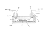
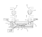
- FIG. 4 examples of a configuration block diagram of a reagent supply device that supplies an anaerobic reagent (here, an anaerobic antibody is taken as an example) into the flow path 14 of the microchip 10 of FIG. Show.
- the reagent supply apparatus shown in FIG. 4 includes a reagent injection mechanism 40, a specimen holding mechanism 20, a reagent recovery mechanism 50, and a control unit 60.
- FIG. 5 is an enlarged view for facilitating understanding of the needle-like fluid discharge means 21 and the needle-like fluid recovery means 22 shown later.
- the reagent injection mechanism 40 includes an injection needle fluid discharge means 21, a fluid discharge means drive mechanism 23, a joint 28 b, a reagent solution injection pipe 26, a joint 28 a, a temperature control unit 31, and a control.
- a valve 42 and a reagent storage unit 41 are included.
- the injection needle-like fluid discharge means 21 penetrates the thin plate portion 11a of the microchip provided in the inlet 13a of the flow path 14 of the microchip 10 and the self-recoverable sealing material 17, and supplies the reagent to the flow path of the microchip 10. 14 to be discharged.
- the injection needle-like fluid discharge means 21 is made of a hollow cylindrical member made of stainless steel.
- the distal end portion 21b of the injection needle-shaped fluid discharge means 21 is closed, and the distal end portion has a needle shape (for example, a bevel shape (an oblique shape) like an injection needle).
- the opening 21a that communicates with the internal cavity of the hollow cylindrical member and discharges the reagent supplied from the internal cavity into the flow path 14 is provided at a position as close as possible to the tip 21b on the side of the cylindrical part of the hollow cylindrical member. Yes.
- the needle-like fluid discharge means 21 is simply referred to as fluid discharge means 21.
- the tip 21b of the fluid discharge means 21 has a bevel shape like an injection needle, so that the thin plate portion 11a of the microchip and the self-healing sealing material 17 can be easily penetrated. Further, since the distal end portion 21b is closed and the opening portion 21a is provided on the side surface of the cylindrical portion 21c of the hollow cylindrical member, when the fluid discharge means 21 penetrates the self-recoverable sealing material 17, it Chips of the restorable sealing material 17 are hardly generated, and the opening 21a is not clogged with the chips of the self-healing sealing material 17.
- the fluid discharge means 21 is driven in the vertical direction by a fluid discharge means drive mechanism 23. That is, in the fluid discharge means driving mechanism 23, the opening 21 a of the fluid discharge means 21 penetrates the thin plate portion 11 a of the microchip 10 and the self-recoverable sealing material 17 and enters the flow path 14 of the microchip 10. The fluid discharge means 21 is driven so that the fluid discharge means 21 is completely detached from the microchip 10 via the thin plate portion 11a of the microchip 10 and the self-healing sealing material 17. To drive.
- the fluid discharge means driving mechanism 23 is connected to, for example, a joint 28b that connects the fluid discharge means 21 and the reagent solution injection pipe 26 to which the reagent is transported.
- one of the reagent solution injection pipes 26 is connected to the fluid discharge means 21 via the joint 28b, and the other is a temperature control unit for controlling the temperature of the reagent delivered from the reagent storage unit 41. 31 is connected to a pipe whose temperature is controlled. Since the fluid discharge means 21 and the joint 28b are driven in the vertical direction by the fluid discharge means drive mechanism 23, the reagent solution injection pipe 26 is also constituted by a flexible pipe so as to be able to cope with these operations.
- the reagent storage unit 41 stores a reagent to be supplied into the flow path 14 of the microchip 10.
- the reagent storage unit 41 includes a PBS storage unit 41 a, an alkanethiol-containing solution storage unit 41 b, an antibody-containing solution storage unit 41 c, an antigen-containing solution storage unit 41 d, and a temperature control unit 33.
- the temperature of the antibody-containing solution storage unit 41 c is controlled by the temperature control unit 33.
- the storage temperature of the antibody is, for example, 4 ° C.
- Each storage unit of the reagent storage unit 41 is connected to a control valve 42 including a three-way valve.
- the reagent storage unit 41 includes four storage units, so that the piping system including the reagent storage unit 41 and the control valve 42 is four systems.
- the control valve 42 a three-way solenoid valve or the like is employed.
- the three-way valve that is the control valve 42 has three ports a, b, and c.
- Each control valve 42 is connected in a manifold shape so that each bc flow path becomes one flow path.
- the a port of each control valve 42 is connected to the reagent storage unit 41.
- a sealing plug is connected to the b port of the control valve 42 connected to the PBS storage unit 41a, and the c port of the control valve 42 connected to the antigen-containing solution storage unit 41d It is connected to a pipe whose temperature is controlled by the temperature controller 31.
- the four piping systems of the reagent storage unit 41 are finally integrated into one piping system and connected to the piping whose temperature is controlled by the temperature control unit 31.
- the temperature control unit 31 is for controlling the temperature of a reagent such as an antibody. Specifically, the temperature control unit 31 controls the temperature of a pipe connected to the pipe from the reagent storage unit 41 integrated in the one pipe system described above. Control.
- One of the pipes whose temperature is controlled by the temperature control unit 31 is connected to the reagent storage unit 41 as described above, and the other is connected to the reagent solution injection pipe 26 by the joint 28a.
- the test specimen holding mechanism 20 includes a temperature control stage 34 including a temperature control unit 32.
- the temperature adjustment stage 34 has a function of adjusting the temperature of the microchip 10 while the microchip 10 is placed thereon.
- the temperature control unit 32 controls the temperature of the temperature adjustment stage 34 to adjust the temperature of the microchip 10 placed on the temperature adjustment stage 34.
- the reagent recovery mechanism 50 includes an injection needle fluid recovery means 22, a fluid recovery means drive mechanism 24, a joint 28 c, a reagent solution discharge pipe 27, a pump 51, and a waste liquid tank 52. .
- the needle-like fluid recovery means 22 penetrates through the self-healing sealing material 17 provided in the discharge port 13b of the microchip channel 14 and removes at least a part of the reagent remaining in the microchip channel 14. It is collected in the waste liquid tank 52.
- the needle-like fluid recovery means 22 is made of a hollow cylindrical member made of stainless steel, like the fluid discharge means 21.
- the distal end portion 22b of the fluid recovery means 22 is closed, and the distal end portion has a needle shape (for example, a bevel shape (an oblique shape) like an injection needle).
- the opening 22a that communicates with the internal cavity of the hollow cylindrical member and discharges the reagent supplied from the internal cavity into the fluid is provided at a position as close as possible to the tip 22b on the side surface of the cylindrical part 22c of the hollow cylindrical member. Yes.
- the needle-like fluid recovery means 22 is simply referred to as fluid recovery means 22.
- the tip 22b of the fluid recovery means 22 has a bevel shape like an injection needle, it is possible to easily penetrate the thin plate portion 11a of the microchip and the self-healing sealing material 17. Furthermore, since the tip 22b is closed and the opening 22a is provided on the side of the cylindrical portion 22c of the hollow cylindrical member, the self-healing when the fluid recovery means 22 penetrates the self-healing sealing material 17 The chip of the sealing material 17 is hardly generated, and the opening 22a is not clogged with the chip of the self-healing sealing material 17.
- the fluid recovery means 22 is driven in the vertical direction by a fluid recovery means drive mechanism 24. That is, in the fluid recovery means driving mechanism 24, the opening 22 a of the fluid recovery means 22 penetrates through the thin plate portion 11 a of the microchip 10 and the self-recoverable sealing material 17 and enters the flow path 14 of the microchip 10.
- the fluid recovery means 22 is driven so that the fluid recovery means 22 is completely detached from the microchip 10 via the thin plate portion 11a of the microchip 10 and the self-healing sealing material 17.
- the fluid recovery means drive mechanism 24 is connected to, for example, a joint 28 c that connects the fluid recovery means 22 and a reagent solution discharge pipe 27 that transports at least a part of the reagent in the flow path 14 to the waste liquid tank 52.
- one of the reagent solution discharge pipes 27 is connected to the fluid recovery means 22 via the joint 28 c and the other is connected to the pump 51. Since the fluid recovery means 22 and the joint 28c are driven in the vertical direction by the fluid recovery means drive mechanism 24, the reagent solution discharge pipe 27 is also composed of a flexible pipe so as to be able to cope with these operations.
- the pump 51 supplies the reagent stored in the reagent storage unit 41 into the flow path 14 of the microchip via the fluid discharge means 21, and at least a part of the reagent in the flow path 14 is disposed in the waste liquid tank.
- the reagent (waste liquid) sent from the pump 51 is stored in the waste liquid tank 52.
- the control unit 60 includes a fluid discharge means driving mechanism 23, a temperature control unit 31, a control valve 42, a temperature control unit 33, a temperature control unit 32 of the specimen holding mechanism 20, and a reagent recovery mechanism belonging to the reagent injection mechanism 40.
- the operation of the fluid recovery means drive mechanism 24 and the pump 51 belonging to 50 is controlled.
- microchip 10 as a test body is placed on the temperature control stage 34.
- the microchip 10 may be placed on the temperature control stage 34 by an operator, or a well-known transport mechanism (not shown) may be used. Note that when the transport mechanism is used, the control unit 60 may control the transport mechanism.
- the temperature control unit 32 of the temperature adjustment stage 34 determines that the temperature of the temperature adjustment stage 34 is a predetermined temperature based on a command from the control unit 60. For example, the temperature is controlled to be 25 to 37 ° C. Similarly, based on a command from the control unit 60, the temperature control unit 31 shown in FIG. 4 controls in advance so that the temperature of the piping of the temperature control unit 31 becomes a predetermined temperature, for example, 25 to 37 ° C.
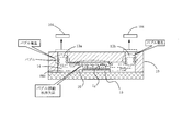
- the fluid discharge means drive mechanism 23 drives the fluid discharge means 21 (injection needle fluid discharge means) downward to a predetermined position. As shown in FIG. 6A, by this driving, the opening 21a of the fluid discharge means 21 passes through the self-healing sealing material 17 provided in the inflow port 13a of the microchip 10, and the microchip 10 It enters the flow path 14.
- the predetermined position is a position where the tip of the fluid discharge means 21 does not contact the second microchip substrate 12 of the microchip 10.
- the fluid recovery means drive mechanism 24 drives the fluid recovery means 22 (injection needle fluid recovery means) downward to a predetermined position.
- the opening 22a of the fluid recovery means 22 passes through the thin plate portion 11a provided in the discharge port 13b of the microchip 10 and the self-recoverable sealing material 17 and It enters into the channel 14 of the microchip.
- the above-described predetermined position is a position where the tip of the fluid recovery means 22 does not contact the second microchip substrate 12 of the microchip 10.
- the controller 60 sets the fluid discharge means 21 and the fluid recovery means 22 so that the position of the lower end of the opening 22a of the fluid recovery means 22 is above the position of the upper end of the opening 21a of the fluid discharge means 21. To do.
- the opening 21a of the fluid discharge means 21 and the opening 22a of the fluid recovery means 22 are set to face each other.
- the control unit 60 starts driving the pump 51.
- air in the flow path 14 of the microchip 10 is first sucked from the opening 22a of the fluid recovery means 22, and then the PBS stored in the PBS storage unit 41a is a- of the control valve 42 belonging to the PBS piping system.
- PBS flows from the opening 21a of the fluid discharge means 21 into the flow path 14 of the microchip 10 via the c flow path, the bc flow path of the other control valve 42, the temperature control section 31, and the reagent solution injection pipe 26. Inflow.
- the PBS injected into the microchip channel 14 from the opening 21a of the fluid discharge unit 21 passes through the channel 14 while washing the fluid, and the fluid recovery unit 22 is discharged from the opening 22 a to the outside of the flow path and sent to the waste liquid tank 52. That is, a PBS flow for washing the flow path is generated in the flow path. Since the position of the lower end of the opening 22a of the fluid recovery means 22 is set to be higher than the position of the upper end of the opening 21a of the fluid discharge means 21, it flows in the flow path 14 as shown in FIG. The liquid level of the PBS is the position of the lower end of the opening 22a of the fluid recovery means 22.
- the control unit 60 switches the flow path of the control valve 42 belonging to the PBS piping system to the bc flow path among the plurality of control valves 42, and
- the flow path of the control valve 42 belonging to the piping system (hereinafter referred to as SAMs piping system) connected to the alkanethiol-containing solution storage unit 41b that stores the alkanethiol-containing solution that is the forming solution is switched to the ac channel. It is assumed that the cleaning time in the PBS (the above-described fixed time) and the flow path switching timing of the control valve 42 belonging to the PBS piping system and the SAMs piping system are stored in the control unit 60 in advance.
- the PBS remaining in the channel 14 of the microchip is sucked from the opening 22a of the fluid recovery means 22, and the alkanethiol stored in the alkanethiol-containing solution storage unit 41b.
- the temperature control section 31 and the reagent solution injection pipe 26 are Into the flow path 14 of the microchip 10 from the opening 21a of the fluid discharge means 21 via the bc flow path of the control valve 42 belonging to the AC piping system. Inflow.
- the alkanethiol-containing solution injected into the microchip channel 14 from the opening 21a of the fluid discharge means 21 is initially flowed before the alkanethiol-containing solution flows. It passes through the channel 14 while being mixed with the PBS remaining in the channel 14, discharged from the opening 22 a of the fluid recovery means 22 to the outside of the channel 14, and sent to the waste liquid tank 52. Eventually, the concentration of PBS gradually decreases, and finally, a flow consisting almost of an alkanethiol-containing solution is generated in the flow path 14.
- the alkanethiol in the alkanethiol-containing solution reacts with the Au thin film, and a self-assembled film (Self-Assembled Monolayer: SAM film) is formed on the Au thin film.
- the liquid level of the flowing alkanethiol-containing solution is the position of the lower end of the opening 22 a of the fluid recovery means 22.
- the control unit 60 selects the control valve 42 belonging to the SAMs piping system among the plurality of control valves 42.
- the flow path is switched to the bc flow path, and the flow path of the control valve 42 belonging to the PBS piping system is switched to the ac flow path.
- the time for the alkanethiol-containing solution to flow through the microchip flow path 14 until the SAM film 16 is formed on the Au film (a certain period of time described above), the control valves 42 belonging to the SAMs piping system and the PBS piping system. It is assumed that the flow path switching timing is stored in the control unit 60 in advance.
- the alkanethiol-containing solution remaining in the channel 14 of the microchip is sucked from the opening 22a of the fluid recovery means 22, and the PBS is connected to the control valve 42 belonging to the PBS piping system.
- the microchip channel 14 Flow into the microchip channel 14 from the opening 21a of the fluid discharge means 21 via the ac channel, the bc channel of the other control valve 42, the temperature control unit 31, and the reagent solution injection pipe 26 To do.
- the PBS injected into the microchip channel 14 from the opening 21a of the fluid discharge means 21 is initially an alkanethiol-containing solution remaining in the channel 14.
- the fluid passes through the flow path 14 while being mixed with the fluid, and is discharged from the opening 22 a of the fluid recovery means to the outside of the flow path 14 and sent to the waste liquid tank 52.
- the concentration of the alkanethiol-containing solution gradually decreases, and finally, a flow consisting almost of PBS is generated in the flow path 14. That is, the alkanethiol-containing solution that has not contributed to the formation of the SAM film 16 is discharged to the outside through the reagent solution discharge pipe 27 together with the PBS.
- the liquid level of the PBS is the position of the lower end of the opening 22a of the fluid recovery means 22.
- the control unit 60 switches the flow path of the control valve 42 belonging to the PBS piping system to the bc flow path among the plurality of control valves 42, and contains the antibody.
- the flow path of the control valve 42 belonging to the piping system (AB piping system) connected to the antibody-containing solution storage unit 41c that stores the solution is switched to the ac channel. It is assumed that the cleaning time in the PBS (the above-described fixed time) and the flow path switching timing of the control valve 42 belonging to the PBS piping system and the AB piping system are stored in the control unit 60 in advance.
- the antibody-containing solution storage unit 41c for example, the antibody-containing solution stored in a low temperature state of 4 ° C. is connected to the pipe of the temperature control unit 31 that is temperature-controlled by the temperature control unit 31 shown in FIG. By passing, it is heated to, for example, 25 to 37 ° C. As described above, the temperature of the microchip 10 placed on the temperature control stage 34 is maintained at, for example, 25 to 37 ° C. by the temperature control stage 34 controlled by the temperature control unit 32. The temperature of the antibody-containing solution that has flowed into the flow path 14 does not drop.
- the antibody-containing solution injected into the microchip channel 14 from the opening 21a of the fluid discharge means 21 is initially flow channel 14 before the antibody-containing solution flows.
- the fluid passes through the flow path 14 while being mixed with the PBS remaining therein, and is discharged from the opening 22 a of the fluid recovery means 22 to the outside of the flow path 14 and sent to the waste liquid tank 52.
- the concentration of PBS gradually decreases, and finally, a flow consisting essentially of an antibody-containing solution is generated in the flow path 14.
- the antibody in the antibody-containing solution reacts with the alkanethiol SAM film 16 and chemically binds thereto, and is immobilized on the SAM film 16. That is, antibody Ig is immobilized on the metal thin film 15.
- the position of the lower end of the opening 22a of the fluid recovery means 22 is set to be higher than the position of the upper end of the opening 21a of the fluid discharge means 21, it flows in the flow path 14 as shown in FIG.
- the liquid level of the antibody-containing solution is at the lower end of the opening 22a of the fluid recovery means 22.
- the position of the lower end of the opening 22a of the fluid recovery means 22 is set so that the level of the antibody Ig fixed to the SAM film 16 is completely immersed in the antibody-containing solution.
- the antibody Ig immobilized on the SAM membrane 16 does not come into contact with air.
- the opening 21a of the fluid discharge means 21 is provided on the side surface of the hollow cylindrical member, the reagent (here, the antibody-containing solution) supplied from the fluid discharge means 21 is hollow. It is discharged from the opening in a direction orthogonal to the axial direction of the cylindrical member. That is, the reagent is released in the lateral direction in FIGS.
- the opening 21a of the fluid discharge means 21 and the opening 22a of the fluid recovery means 22 are set so as to face each other, and the antibody-containing solution released from the opening 21a in the lateral direction.
- the setting of the fluid discharge means 21 and the fluid recovery means 22 in the procedure (1) is such that the position of the lower end of the opening 22a of the fluid recovery means 22 and the position of the opening 21a of the fluid discharge means 21 are as described above. Done to be set.
- (6) Cleaning in the flow path with PBS After a certain period of time has passed and the antibody Ig is fixed on the SAM film 16, the control unit 60 selects the control valve 42 belonging to the AB piping system from among the plurality of control valves 42. The flow path is switched to the bc flow path, and the flow path of the control valve 42 belonging to the PBS piping system is switched to the ac flow path.
- the alkanethiol-containing solution remaining in the channel 14 of the microchip is sucked from the opening 22a of the fluid recovery means 22, and the PBS is connected to the control valve 42 belonging to the PBS piping system.
- the non-fixed antibody Ig remaining on the surface of the antibody Ig fixed to the SAM film 16, or the antibody remaining in the region other than the SAM film 16 Ig is discharged to the outside through the reagent solution discharge pipe 27 together with PBS.
- the liquid level of the PBS is the position of the lower end of the opening 22a of the fluid recovery means 22. Since the level of the liquid is such that the antibody Ig fixed to the SAM film 16 is completely immersed in PBS, the antibody Ig fixed to the SAM film 16 does not come into contact with air.
- the antibody Ig is immobilized on the reagent arrangement region (SAM film formation region on the metal thin film 15) in the microchip channel 14.
- the metal thin film 15 is always PBS, a SAM film forming solution (alkanethiol-containing solution in the above example), Immerse in the antibody-containing solution.
- the SAM film formation in the procedure (3) is performed without air contacting the metal thin film 15.
- the antibody fixation to the SAM film 16 in the procedure (5) is performed without contact of air with the antibody Ig under the condition that no air remains in the SAM film 16.
- the discharge of the antibody Ig not fixed to the SAM film 16 in the procedure (6) is also performed without contact of air with the antibody Ig fixed to the SAM film 16.
- this is because the liquid level of the reagent flowing in the flow path 14 is such that the antibody Ig fixed to the SAM film 16 is completely immersed in the reagent by the opening of the fluid recovery means 22. This is because the position of the lower end of the portion 22a is set.
- the reagent supply apparatus using the microchip 10 of the present invention can supply an anaerobic reagent such as an anaerobic antibody to the reagent arrangement region of the microchip 10 without contacting air. That is, it becomes possible to fix the anaerobic antibody to the reagent arrangement region of the microchip 10 without deactivating it.
- the reagent is supplied to the flow path 14 of the microchip 10 mechanically by the control unit 60, the reagent injection mechanism 40, and the reagent recovery mechanism 50, the flow path 14 of the microchip 10 can be stably distributed.
- the reagent can be supplied to the flow path 14 of the microchip 10 mechanically by the control unit 60, the reagent injection mechanism 40, and the reagent recovery mechanism 50, the flow path 14 of the microchip 10 can be stably distributed.
- the reagent can be supplied to the flow path 14 of the microchip 10 mechanically by the control unit 60, the reagent injection mechanism 40, and the reagent recovery mechanism 50, the flow path 14 of the
- the opening 21a of the fluid discharge means 21 and the opening 22a of the fluid recovery means 22 are set so as to face each other, and the antibody-containing solution released from the opening in the lateral direction is directly at the corner of the flow path 14.
- the position of the opening 21a of the fluid discharge means 21 so as not to collide with the part, the antibody-containing solution flowing in the flow path 14 is suppressed from becoming turbulent. Therefore, the contact between the antibody Ig in the antibody-containing solution and the SAM film 16 of alkanethiol is hardly disturbed, the reaction between the antibody Ig and the SAM film 16 proceeds well, and the antibody Ig is stably immobilized on the SAM film 16. It becomes possible.
- the microchip 10 has a structure in which the inlet 13a and the outlet 13b of the flow path 14 of the present invention are sealed with a self-recoverable sealing material 17 made of, for example, silicone gel. Even when the fluid discharge means 21 and the fluid recovery means 22 of the reagent supply apparatus of the present invention penetrate the microchip thin plate portion 11a and the self-healing sealing material 17 and enter the reagent arrangement region, the self-healing seal Since the stopper 17 is deformed when a force is applied and returns to a shape before the force is applied when the force is released, the self-restoring sealing material 17, the fluid discharge means 21, and the fluid recovery means 22 are provided. Adhesiveness at the contact portion is good, and outside air hardly enters the reagent arrangement region which is a closed space from this contact portion.
- a self-recoverable sealing material 17 made of, for example, silicone gel.
- the control unit 60 sets the flow path of the control valve 42 belonging to the PBS piping system among the plurality of control valves 42 to b- While switching to the c flow path, the flow path of the control valve 42 belonging to the piping system (AC piping system) connected to the antigen-containing solution storage unit 41d for storing the antigen-containing solution is switched to the ac flow path. It is assumed that the cleaning time in PBS (the above-described fixed time) and the flow path switching timing of the control valve 42 belonging to the PBS piping system and the AC piping system are stored in the control unit 60 in advance.
- the PBS remaining in the channel of the microchip 10 is sucked from the opening 22a of the fluid recovery means 22, and the antigen-containing solution a of the control valve 42 belonging to the AC piping system. It flows into the microchip channel 14 from the opening 21a of the fluid discharge means 21 via the -c channel, the temperature control unit 31, and the reagent solution injection tube 26.
- the antigen-containing solution is transferred to the bc flow path side of the control valve 42 belonging to the AB piping system, It does not flow to the bc flow path side of the control valve 42 belonging to the SAMs piping system and to the bc flow path side of the control valve 42 belonging to the PBS piping system.
- the antigen-containing solution is heated to, for example, 25 to 37 ° C. by passing through the piping of the temperature control unit 31 that is temperature-controlled by the temperature control unit 31 shown in FIG.
- the antigen-containing solution injected from the opening 21a of the fluid discharge means 21 into the channel 14 of the microchip is initially channeled before the antigen-containing solution flows.
- the fluid passes through the flow path 14 while being mixed with the PBS remaining therein, and is discharged from the opening 22 a of the fluid recovery means 22 to the outside of the flow path 14 and sent to the waste liquid tank 52.
- the concentration of PBS gradually decreases, and finally, a flow consisting almost of an antigen-containing solution is generated in the flow path 14.
- the antigen in the antigen-containing solution undergoes an antibody-antigen reaction with the antibody Ig immobilized on the SAM film 16 and chemically binds thereto.
- the antibody-antigen reaction is performed in an antigen-containing solution that does not contain air, depending on the settings of the fluid discharge means 21 and the fluid recovery means 22 in the procedure (1).
- the temperature of the microchip 10 placed on the temperature control stage 34 is maintained at, for example, 25 to 37 ° C. by the temperature control stage 34 controlled by the temperature control unit 32.
- the antibody-antigen reaction performed in the flow path 14 is performed under a temperature condition of 25 to 37 ° C. This temperature condition conforms to human body temperature.
- the control unit 60 sets the flow path of the control valve 42 belonging to the AC piping system to b- While switching to the c channel, the channel of the control valve 42 belonging to the PBS piping system is switched to the ac channel.
- the time for the antigen-containing solution to flow through the microchip flow path 14 until the antibody-antigen reaction is completed (a certain period of time as described above), and the flow path switching timing of the control valve 42 belonging to the AC piping system and the PBS piping system are as follows. Suppose that it is stored in the control unit 60 in advance.
- the antigen-containing solution remaining in the channel 14 of the microchip is sucked from the opening 22a of the fluid recovery means 22, and the PBS of the control valve 42 belonging to the PBS piping system is a. -C flow path, bc flow path of other control valve 42, temperature control section 31, and reagent solution injection pipe 26, and flows into the microchip flow path 14 from the opening 21a of the fluid discharge means 21. .
- the antigen that has not contributed to the antibody-antigen reaction remaining in the flow path is discharged to the outside through the reagent solution discharge pipe 27 together with PBS.
- an antigen is supplied to the antibody Ig fixed in the flow path 14 of the microchip, and an antibody-antigen reaction is generated.
- the generation of the antibody antigen reaction in the procedure (7) is performed without contact of air with the antibody Ig fixed to the SAM membrane 16.
- emission of the antigen which did not contribute to the antibody antigen reaction which remained in the flow path in a procedure (8) is also performed, without air contacting antibody Ig.
- this is because the level of the reagent flowing in the flow path is such that the antibody Ig fixed to the SAM film 16 is completely immersed in the antibody-containing solution. This is because the lower end position is set.
- the reagent supply apparatus using the microchip 10 of the present invention can supply the antigen to the reagent arrangement region of the microchip 10 without bringing air into contact therewith. Therefore, it is possible to generate an antigen-antibody reaction without deactivating the anaerobic antibody Ig fixed in the reagent arrangement region of the microchip 10.
- the reagent is supplied to the microchip flow path 14 mechanically by the control unit 60, the reagent injection mechanism 40, and the reagent recovery mechanism 50, the microchip flow path 14 can be stably supplied to the microchip. Reagents can be supplied.
- the control unit 60 controls among the plurality of control valves 42 that belong to the PBS piping system.
- the flow path 14 of the valve 42 is switched to the bc flow path. It is assumed that the cleaning time with PBS (the above-described fixed time) and the flow path switching timing of the control valve 42 belonging to the PBS piping system are stored in the control unit 60 in advance.
- the control unit 60 stops driving the pump 51.
- the flow consisting essentially of PBS in the flow path 14 of the microchip stops.
- the position of the lower end of the opening of the fluid recovery means 22 is higher than the position of the upper end of the opening of the fluid discharge means 21 (injection needle fluid discharge means). Since it is set, as shown in FIG. 5, the liquid level of the PBS is the position of the lower end of the opening 22a of the fluid recovery means 22.
- the position of the lower end of the opening 22a of the fluid recovery means 22 is set so that the level of the antibody Ig fixed on the SAM film 16 is completely immersed in PBS. The antibody Ig that has completed the antibody-antigen reaction fixed to the membrane 16 does not come into contact with air.
- the fluid discharge means driving mechanism 23 drives the fluid discharge means 21 upward to a predetermined position. As shown in FIG. 8 (i), the opening 21a of the fluid discharge means 21 leaves the microchip flow path 14 by this driving.
- the predetermined position is such that the fluid discharge means 21 is completely detached from the microchip 10 via the thin plate portion 11a provided at the injection port of the microchip 10 and the self-recoverable sealing material 17. Position.
- the fluid recovery means driving mechanism 24 drives the fluid recovery means 22 upward to a predetermined position. As shown in FIG. 8 (i), this driving causes the opening 22a of the fluid recovery means 22 to leave the microchip channel 14. Note that the above-mentioned predetermined position means that the fluid recovery means 22 is completely detached from the microchip 10 via the thin plate portion 11 a provided in the discharge port 13 b of the microchip 10 and the self-recoverable sealing material 17. It is the position.
- the fluid discharge means 21 and the fluid recovery means 22 penetrating the thin plate portion 11a and the self-healing sealing material 17 of the microchip 10 are detached via the thin plate portion 11a and the self-healing sealing material 17.
- the self-healing sealing material 17 is deformed when a force is applied and returns to the shape before the force is applied when the force is released, the thin plate portion 11a and the self-healing sealing material 17 are restored.
- the holes generated in the thin plate portion 11a are maintained by the fluid discharge means 21 and the fluid recovery means 22 that pass through and leave, but the holes generated in the self-healing sealing material 17 are quickly closed. Therefore, the inflow of air from the outside into the flow path is prevented even after the fluid discharge means 21 and the fluid recovery means 22 are separated from the thin plate portion 11a of the microchip and the self-healing sealing material 17.
- the microchip 10 placed on the temperature control stage 34 is carried out to a measuring instrument for measuring the antibody-antigen reaction.
- the operator may carry out the microchip 10 to the measuring instrument or may use a known transport mechanism that is not shown.
- the control unit 60 may control the transport mechanism.
- the temperature control unit 32 of the temperature adjustment stage 34 stops the temperature control of the temperature adjustment stage 34 based on a command from the control unit 60.
- the temperature control unit 31 illustrated in FIG. 14 stops the temperature control of the piping of the temperature control unit 31.
Landscapes
- Health & Medical Sciences (AREA)
- Chemical & Material Sciences (AREA)
- Immunology (AREA)
- Life Sciences & Earth Sciences (AREA)
- General Health & Medical Sciences (AREA)
- Analytical Chemistry (AREA)
- Hematology (AREA)
- Engineering & Computer Science (AREA)
- Biochemistry (AREA)
- General Physics & Mathematics (AREA)
- Pathology (AREA)
- Physics & Mathematics (AREA)
- Biomedical Technology (AREA)
- Urology & Nephrology (AREA)
- Molecular Biology (AREA)
- Clinical Laboratory Science (AREA)
- Chemical Kinetics & Catalysis (AREA)
- Dispersion Chemistry (AREA)
- Biotechnology (AREA)
- Cell Biology (AREA)
- Microbiology (AREA)
- Food Science & Technology (AREA)
- Medicinal Chemistry (AREA)
- Automatic Analysis And Handling Materials Therefor (AREA)
Priority Applications (2)
| Application Number | Priority Date | Filing Date | Title |
|---|---|---|---|
| CN201380013928.7A CN104246512B (zh) | 2012-05-22 | 2013-05-14 | 向微芯片供给试剂的方法、微芯片及向微芯片供给试剂的试剂供给装置 |
| US14/402,652 US9977043B2 (en) | 2012-05-22 | 2013-05-14 | Method of supplying reagent to microchip, microchip, and device for supplying reagent to microchip |
Applications Claiming Priority (2)
| Application Number | Priority Date | Filing Date | Title |
|---|---|---|---|
| JP2012-116367 | 2012-05-22 | ||
| JP2012116367A JP5692164B2 (ja) | 2012-05-22 | 2012-05-22 | マイクロチップへの試薬供給方法及びマイクロチップへの試薬供給装置 |
Publications (1)
| Publication Number | Publication Date |
|---|---|
| WO2013175996A1 true WO2013175996A1 (ja) | 2013-11-28 |
Family
ID=49623690
Family Applications (1)
| Application Number | Title | Priority Date | Filing Date |
|---|---|---|---|
| PCT/JP2013/063362 Ceased WO2013175996A1 (ja) | 2012-05-22 | 2013-05-14 | マイクロチップへの試薬供給方法及びマイクロチップ並びにマイクロチップへの試薬供給装置 |
Country Status (4)
| Country | Link |
|---|---|
| US (1) | US9977043B2 (enExample) |
| JP (1) | JP5692164B2 (enExample) |
| CN (1) | CN104246512B (enExample) |
| WO (1) | WO2013175996A1 (enExample) |
Cited By (1)
| Publication number | Priority date | Publication date | Assignee | Title |
|---|---|---|---|---|
| CN109374730A (zh) * | 2018-11-14 | 2019-02-22 | 江苏科技大学 | 用于qcm和lspr双技术生物分子检测的恒温测量池 |
Families Citing this family (16)
| Publication number | Priority date | Publication date | Assignee | Title |
|---|---|---|---|---|
| GB0724736D0 (en) | 2007-12-19 | 2008-01-30 | Oxford Nanolabs Ltd | Formation of layers of amphiphilic molecules |
| GB201202519D0 (en) | 2012-02-13 | 2012-03-28 | Oxford Nanopore Tech Ltd | Apparatus for supporting an array of layers of amphiphilic molecules and method of forming an array of layers of amphiphilic molecules |
| GB201313121D0 (en) | 2013-07-23 | 2013-09-04 | Oxford Nanopore Tech Ltd | Array of volumes of polar medium |
| JP2014235115A (ja) * | 2013-06-04 | 2014-12-15 | ウシオ電機株式会社 | マイクロチップおよびマイクロチップにおける金属薄膜の成膜方法 |
| US11333674B2 (en) | 2015-11-16 | 2022-05-17 | Otsuka Pharmaceutical Co., Ltd. | Test kit, liquid delivery method and testing apparatus using test kit |
| JP6953679B2 (ja) * | 2016-03-30 | 2021-10-27 | ソニーグループ株式会社 | 試料分取キット、試料分取装置 |
| GB201611770D0 (en) | 2016-07-06 | 2016-08-17 | Oxford Nanopore Tech | Microfluidic device |
| GB2568895B (en) * | 2017-11-29 | 2021-10-27 | Oxford Nanopore Tech Ltd | Microfluidic device |
| CN110856822B (zh) * | 2018-08-22 | 2021-02-23 | 厦门大学 | 连通器、其与试剂模块的组合及微流控芯片 |
| JP6896685B2 (ja) * | 2018-09-18 | 2021-06-30 | 株式会社東芝 | 液膜維持装置及びケミカルセンサ |
| CN111220767A (zh) * | 2018-11-23 | 2020-06-02 | 京元电子股份有限公司 | 用于生物芯片测试的弹性缓冲座及其测试模块与测试设备 |
| KR20210138594A (ko) | 2019-03-12 | 2021-11-19 | 옥스포드 나노포어 테크놀로지즈 피엘씨 | 나노포어 감지 디바이스 및 이를 작동하는 방법 및 형성하는 방법 |
| WO2022013551A1 (en) | 2020-07-17 | 2022-01-20 | Oxford Nanopore Technologies Limited | Nanopore sensing device |
| JP2022119563A (ja) * | 2021-02-04 | 2022-08-17 | 株式会社エンプラス | 流体取扱装置 |
| US20230256438A1 (en) * | 2022-02-14 | 2023-08-17 | Lifeos Genomics Corporation | Microfluidic cartridge |
| EP4410426A1 (en) * | 2023-01-31 | 2024-08-07 | LifeOS Genomics Corporation | Microfluidic cartridge |
Citations (5)
| Publication number | Priority date | Publication date | Assignee | Title |
|---|---|---|---|---|
| JP2005308668A (ja) * | 2004-04-26 | 2005-11-04 | Hitachi Maxell Ltd | 反応装置 |
| JP2005315685A (ja) * | 2004-04-28 | 2005-11-10 | Hitachi Maxell Ltd | 流体デバイス |
| JP2009063474A (ja) * | 2007-09-07 | 2009-03-26 | Konica Minolta Medical & Graphic Inc | マイクロチップ |
| JP2011080855A (ja) * | 2009-10-07 | 2011-04-21 | Rohm Co Ltd | マイクロチップ |
| JP2011220996A (ja) * | 2010-03-23 | 2011-11-04 | Hitachi High-Technologies Corp | マイクロ流路チップ及びマイクロアレイチップ |
Family Cites Families (8)
| Publication number | Priority date | Publication date | Assignee | Title |
|---|---|---|---|---|
| US7223363B2 (en) * | 2001-03-09 | 2007-05-29 | Biomicro Systems, Inc. | Method and system for microfluidic interfacing to arrays |
| JP4133803B2 (ja) * | 2001-05-25 | 2008-08-13 | 株式会社日立製作所 | 核酸精製構造体 |
| US20030062067A1 (en) * | 2001-09-23 | 2003-04-03 | Irm, Llc | Closed cell washer |
| DE10307227A1 (de) * | 2003-02-14 | 2004-08-26 | Cytocentrics Ccs Gmbh | Verfahren und Vorrichtung zum Kontaktieren einer Mikrofluidstruktur |
| JP3714338B2 (ja) | 2003-04-23 | 2005-11-09 | ウシオ電機株式会社 | 接合方法 |
| JP4993243B2 (ja) | 2005-01-06 | 2012-08-08 | 日本フイルコン株式会社 | 樹脂製微小流路化学デバイスの製造方法並びに該製法により製造された樹脂製微小流路化学デバイス構造体 |
| US8182767B2 (en) * | 2005-12-27 | 2012-05-22 | Honeywell International Inc. | Needle-septum interface for a fluidic analyzer |
| JP5222599B2 (ja) * | 2007-07-20 | 2013-06-26 | 株式会社日立ハイテクノロジーズ | 核酸分析デバイス及びそれを用いた核酸分析装置 |
-
2012
- 2012-05-22 JP JP2012116367A patent/JP5692164B2/ja not_active Expired - Fee Related
-
2013
- 2013-05-14 WO PCT/JP2013/063362 patent/WO2013175996A1/ja not_active Ceased
- 2013-05-14 US US14/402,652 patent/US9977043B2/en active Active
- 2013-05-14 CN CN201380013928.7A patent/CN104246512B/zh active Active
Patent Citations (5)
| Publication number | Priority date | Publication date | Assignee | Title |
|---|---|---|---|---|
| JP2005308668A (ja) * | 2004-04-26 | 2005-11-04 | Hitachi Maxell Ltd | 反応装置 |
| JP2005315685A (ja) * | 2004-04-28 | 2005-11-10 | Hitachi Maxell Ltd | 流体デバイス |
| JP2009063474A (ja) * | 2007-09-07 | 2009-03-26 | Konica Minolta Medical & Graphic Inc | マイクロチップ |
| JP2011080855A (ja) * | 2009-10-07 | 2011-04-21 | Rohm Co Ltd | マイクロチップ |
| JP2011220996A (ja) * | 2010-03-23 | 2011-11-04 | Hitachi High-Technologies Corp | マイクロ流路チップ及びマイクロアレイチップ |
Cited By (1)
| Publication number | Priority date | Publication date | Assignee | Title |
|---|---|---|---|---|
| CN109374730A (zh) * | 2018-11-14 | 2019-02-22 | 江苏科技大学 | 用于qcm和lspr双技术生物分子检测的恒温测量池 |
Also Published As
| Publication number | Publication date |
|---|---|
| US9977043B2 (en) | 2018-05-22 |
| CN104246512B (zh) | 2016-04-13 |
| JP2013242247A (ja) | 2013-12-05 |
| JP5692164B2 (ja) | 2015-04-01 |
| CN104246512A (zh) | 2014-12-24 |
| US20150153371A1 (en) | 2015-06-04 |
Similar Documents
| Publication | Publication Date | Title |
|---|---|---|
| JP5692164B2 (ja) | マイクロチップへの試薬供給方法及びマイクロチップへの試薬供給装置 | |
| US11938710B2 (en) | Microfluidic assay assemblies and methods of manufacture | |
| CN101454664B (zh) | 血浆分离用微流路 | |
| JP4888394B2 (ja) | マイクロリアクタおよびそれを用いた送液方法 | |
| JP2021060118A (ja) | マイクロ流体バルブおよびマイクロ流体デバイス | |
| US20200070167A1 (en) | Processing systems for isolating and enumerating cells or particles | |
| JPWO2006123578A1 (ja) | 検体中の標的物質を分析するための検査チップおよびマイクロ総合分析システム | |
| JPWO2006106643A1 (ja) | マイクロ総合分析システム、検査用チップ、及び検査方法 | |
| JP2006234791A (ja) | 反応器、マイクロリアクタチップ、及びマイクロリアクタシステム、並びに反応器の製造方法 | |
| JP2006266923A (ja) | マイクロ総合分析システム | |
| JPWO2006112498A1 (ja) | 検体を分析するための検査チップおよびマイクロ分析システム | |
| JP6133446B2 (ja) | フローセルおよび送液システム | |
| JP4682874B2 (ja) | マイクロリアクタ | |
| JP5970959B2 (ja) | マイクロプレートへの試薬供給方法及びマイクロプレートへの試薬供給装置 | |
| JP2007136379A (ja) | マイクロリアクタおよびその製造方法 | |
| JP2007083191A (ja) | マイクロリアクタ | |
| JP2007108075A (ja) | 分析用マイクロチップ及びこれを用いた分析用マイクロチップ装置並びにその再利用方法 | |
| JP5794375B2 (ja) | マイクロチップ及びマイクロチップの製造方法 | |
| JP6372985B2 (ja) | マイクロチップおよびマイクロチップの製造方法 | |
| JP6535958B2 (ja) | バルブ、流体デバイス、流体制御方法及びバルブの製造方法 | |
| JP2007322284A (ja) | マイクロチップおよびマイクロチップへの試薬の充填方法 | |
| JP2012198050A (ja) | マイクロチップ、サンプル液供給装置、サンプル液供給方法及び分析装置 | |
| JP2007139501A (ja) | マイクロチップへの試薬の充填方法 | |
| JP4787695B2 (ja) | マイクロリアクターシステム | |
| JP2007139500A (ja) | マイクロチップおよびマイクロ総合分析システム |
Legal Events
| Date | Code | Title | Description |
|---|---|---|---|
| 121 | Ep: the epo has been informed by wipo that ep was designated in this application |
Ref document number: 13794568 Country of ref document: EP Kind code of ref document: A1 |
|
| WWE | Wipo information: entry into national phase |
Ref document number: 14402652 Country of ref document: US |
|
| NENP | Non-entry into the national phase |
Ref country code: DE |
|
| 122 | Ep: pct application non-entry in european phase |
Ref document number: 13794568 Country of ref document: EP Kind code of ref document: A1 |