WO2013175533A1 - 波動歯車装置の波動発生器 - Google Patents
波動歯車装置の波動発生器 Download PDFInfo
- Publication number
- WO2013175533A1 WO2013175533A1 PCT/JP2012/003377 JP2012003377W WO2013175533A1 WO 2013175533 A1 WO2013175533 A1 WO 2013175533A1 JP 2012003377 W JP2012003377 W JP 2012003377W WO 2013175533 A1 WO2013175533 A1 WO 2013175533A1
- Authority
- WO
- WIPO (PCT)
- Prior art keywords
- roller
- gear
- flexible external
- peripheral surface
- rollers
- Prior art date
Links
Images


Classifications
-
- F—MECHANICAL ENGINEERING; LIGHTING; HEATING; WEAPONS; BLASTING
- F16—ENGINEERING ELEMENTS AND UNITS; GENERAL MEASURES FOR PRODUCING AND MAINTAINING EFFECTIVE FUNCTIONING OF MACHINES OR INSTALLATIONS; THERMAL INSULATION IN GENERAL
- F16H—GEARING
- F16H1/00—Toothed gearings for conveying rotary motion
- F16H1/28—Toothed gearings for conveying rotary motion with gears having orbital motion
- F16H1/32—Toothed gearings for conveying rotary motion with gears having orbital motion in which the central axis of the gearing lies inside the periphery of an orbital gear
-
- F—MECHANICAL ENGINEERING; LIGHTING; HEATING; WEAPONS; BLASTING
- F16—ENGINEERING ELEMENTS AND UNITS; GENERAL MEASURES FOR PRODUCING AND MAINTAINING EFFECTIVE FUNCTIONING OF MACHINES OR INSTALLATIONS; THERMAL INSULATION IN GENERAL
- F16H—GEARING
- F16H1/00—Toothed gearings for conveying rotary motion
- F16H1/28—Toothed gearings for conveying rotary motion with gears having orbital motion
-
- F—MECHANICAL ENGINEERING; LIGHTING; HEATING; WEAPONS; BLASTING
- F16—ENGINEERING ELEMENTS AND UNITS; GENERAL MEASURES FOR PRODUCING AND MAINTAINING EFFECTIVE FUNCTIONING OF MACHINES OR INSTALLATIONS; THERMAL INSULATION IN GENERAL
- F16H—GEARING
- F16H49/00—Other gearings
- F16H49/001—Wave gearings, e.g. harmonic drive transmissions
-
- F—MECHANICAL ENGINEERING; LIGHTING; HEATING; WEAPONS; BLASTING
- F16—ENGINEERING ELEMENTS AND UNITS; GENERAL MEASURES FOR PRODUCING AND MAINTAINING EFFECTIVE FUNCTIONING OF MACHINES OR INSTALLATIONS; THERMAL INSULATION IN GENERAL
- F16H—GEARING
- F16H1/00—Toothed gearings for conveying rotary motion
- F16H1/28—Toothed gearings for conveying rotary motion with gears having orbital motion
- F16H1/32—Toothed gearings for conveying rotary motion with gears having orbital motion in which the central axis of the gearing lies inside the periphery of an orbital gear
- F16H2001/327—Toothed gearings for conveying rotary motion with gears having orbital motion in which the central axis of the gearing lies inside the periphery of an orbital gear with orbital gear sets comprising an internally toothed ring gear
-
- Y—GENERAL TAGGING OF NEW TECHNOLOGICAL DEVELOPMENTS; GENERAL TAGGING OF CROSS-SECTIONAL TECHNOLOGIES SPANNING OVER SEVERAL SECTIONS OF THE IPC; TECHNICAL SUBJECTS COVERED BY FORMER USPC CROSS-REFERENCE ART COLLECTIONS [XRACs] AND DIGESTS
- Y10—TECHNICAL SUBJECTS COVERED BY FORMER USPC
- Y10T—TECHNICAL SUBJECTS COVERED BY FORMER US CLASSIFICATION
- Y10T74/00—Machine element or mechanism
- Y10T74/19—Gearing
Definitions
- the present invention relates to a wave gear device, and more particularly, to a roller-type wave generator that flexes a cup-shaped or top hat-shaped flexible external gear into an ellipse shape with a plurality of rollers and meshes with a rigid internal gear.
- a roller type wave generator As a wave generator of a wave gear device, a roller type wave generator is known.
- This roller-type wave generator includes a plurality of rollers in order to bend the flexible external gear of the wave gear device into an elliptical shape.
- Patent Documents 1 and 2 disclose a two-roller type wave generator in which a cup-shaped flexible external gear is bent elliptically by two rollers.
- Patent Document 3 discloses a two-roller type wave generator, a pair of rollers arranged on the major axis of a cup-shaped flexible external gear bent in an elliptical shape, a major axis and a minor axis.
- a six-roller type wave generator with two pairs of rollers arranged between the two is disclosed.
- the amount of bending becomes the distance from the diaphragm. Increase accordingly.
- the direction of the central axis 101 of the flexible external gear 100 is the x axis and the radial direction is the y axis.
- the flexible external gear 100 includes a cylindrical body portion 102 that can be bent in the radial direction, and external teeth 104 are formed on the outer peripheral surface portion on the side of the opening edge 103 on the tip side. ing.
- a diaphragm 105 spreading inward in the radial direction is continuous with the rear end of the cylindrical body 102, and a thick annular boss 106 is continuously formed on the inner peripheral edge of the diaphragm 105.
- the external tooth forming portion where the external teeth 104 are formed is bent in an elliptical shape by a wave generator (not shown).
- a wave generator rotates
- the cylindrical body portion 102 and the diaphragm 105 of the flexible external gear 100 are repeatedly bent as schematically shown in the drawing.
- a broken line A At the site on the long axis of the cylindrical body 102 bent in an elliptical shape, as indicated by a broken line A, from the diaphragm 105 toward the opening edge 103 from the diaphragm 105 along the tooth trace direction of the external tooth 104.
- the amount of bending outward in the radial direction increases substantially in proportion to the distance.
- the amount of inward bending in the radial direction increases substantially in proportion to the distance from the diaphragm 105.
- the inner peripheral surface 107 of the external tooth forming portion of the flexible external gear 100 is most inclined with respect to the central axis 101 of the flexible external gear 100 at the major axis position and the minor axis position.
- the center axis of each roller is supported so as to be parallel to the center axis of the flexible external gear 100.
- the circular outer peripheral surface of the roller (the circular outer peripheral surface of the roller bearing outer ring) is biased in the contact portion with the inner peripheral surface 107 of the outer tooth forming portion in the direction of the external teeth.
- the roller arranged on the long axis causes a large deviation in the contact portion with the inner peripheral surface 107 of the external tooth forming portion.
- the angle transmission accuracy which is an important characteristic of the wave gear device, may be deteriorated.
- an object of the present invention is to propose a roller-type wave generator having a structure in which a contact portion is not biased between a cup-shaped or top-hat-shaped flexible external gear. .
- the cup-shaped or top-hat-shaped flexible external gear has its external tooth forming portion bent in an elliptical shape by a roller type wave generator.
- the inclination matches the inclination of the inner peripheral surface of the external tooth forming portion.
- the inclination of the outer peripheral surface of the roller located on the long axis of the external tooth forming portion bent in an elliptical shape is set.
- the roller center axis may be inclined.
- the roller center axis is set to be parallel to the center axis of the flexible external gear, the circular outer peripheral surface of the roller is a tapered surface, and the taper angle matches the inclination of the inner peripheral surface of the external tooth forming part. It may be.
- each roller of the wave generator that is in contact with a portion other than the long axis position on the inner peripheral surface of the outer tooth forming portion bent in an elliptical shape, the inner peripheral surface of the outer tooth forming portion at each position It is desirable to incline the outer peripheral surface of the roller so that the inclination matches the inclination. In this way, each roller of the wave generator can be brought into contact with the inner peripheral surface of the external tooth forming portion of the flexible external gear without any deviation.
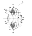
- FIG. 1 It is a schematic front view which shows the wave gear apparatus to which this invention is applied. It is a schematic longitudinal cross-sectional view of the wave gear apparatus of FIG. It is a perspective view which shows the wave generator of the wave gear apparatus of FIG. It is a schematic diagram which shows the arrangement
- the magnitude of the angle transmission error when the conventional two-rotor type wave generator and the six-roller type wave generator of the present invention are used when the angle transmission error of the conventional six-roller type wave generator is used as a reference. It is a graph which shows the ratio of. It is explanatory drawing which shows another example of a roller. It is explanatory drawing which shows the bending state of a cup-shaped flexible external gear.
- the wave gear device 1 is called a cup type, and has an annular rigid internal gear 2, a cup-shaped flexible external gear 3 disposed inside the rigid internal gear 2, and this flexible And a 6-roller type wave generator 4 disposed inside the external external gear 3.
- the flexible external gear 3 is bent in an elliptical shape by the wave generator 4, and the portion of the external teeth located on the long axis L1 in the flexible external gear 3 bent in the elliptical shape is rigid. It meshes with the internal teeth of the internal gear 2.
- the meshing positions of both gears 2 and 3 move in the circumferential direction, and the number of teeth difference between both gears 2 and 3 is 2n (n is a positive integer). Relative rotation occurs between the gears 2 and 3.
- the difference in the number of teeth is generally set to two. For example, when the rigid internal gear 2 is fixed so as not to rotate, the flexible external gear 3 rotates the wave generator 4 (input rotation). Therefore, the rotation speed can be taken out from the flexible external gear 3 to the load side.
- the rigid internal gear 2 includes an annular rigid member 21 and internal teeth 22 formed on the circular inner peripheral surface of the rigid member 21.
- Bolt holes 23 are formed in the rigid member 21 at predetermined intervals along the circumferential direction, and the bolt holes 23 penetrate the rigid member 21 in the direction of the apparatus center axis 1a.
- the cup-shaped flexible external gear 3 includes a cylindrical body 31 that can be bent in the radial direction, and a diaphragm 32 that extends continuously inward in the radial direction from the rear end of the cylindrical body 31. And a thick annular boss 33 formed continuously on the inner peripheral edge of the diaphragm 32. Bolt holes 34 for attachment are formed in the boss 33 at predetermined angular intervals in the circumferential direction. External teeth 36 are formed on the outer peripheral surface portion of the cylindrical body 31 on the opening edge 35 side of the cylindrical body 31.
- FIG. 3 is a perspective view showing the wave generator 4. 1 to 3, the wave generator 4 is formed as a hollow input shaft 41 and coaxially fixed to the outer peripheral surface of the hollow input shaft 41 or as an integral part of the hollow input shaft 41.
- a support disk 42 and six rollers 51 to 56 attached to the support disk 42 are provided.
- the rollers 51 and 52 are a pair of first rollers disposed at point-symmetrical positions with respect to the center of the flexible external gear 3.
- the rollers 53 and 54 are a pair of second rollers disposed at point-symmetrical positions with respect to the center of the flexible external gear 3, and the rollers 55 and 56 are also the center of the flexible external gear 3. It is a pair of 3rd roller arrange
- the pair of first rollers 51 and 52 is positioned on the long axis L1 of the flexible external gear 3 bent into an elliptical shape, and the external teeth 36 in the flexible external gear 3 are formed. In a state where the inner peripheral surface 37 is bent outward, the inner peripheral surface 37 is in contact with the inner peripheral surface 37.
- the pair of second rollers 53 and 54 are disposed between the major axis L1 and the minor axis L2 at positions rotated by a predetermined angle clockwise from the major axis L1, and form external teeth of the flexible external gear 3. The part is in contact with the inner peripheral surface 37 in a state where the inner peripheral surface 37 is bent outward.
- the pair of third rollers 55 and 56 has the inner peripheral surface 37 of the flexible external gear 3 outward at a position symmetrical with respect to the pair of second rollers 53 and 54 with the major axis L1 being sandwiched therebetween. In the bent state, it abuts on the inner peripheral surface 37.
- the first roller 51 includes a support shaft 61 fixed to the end surface 42 a of the support disk 42, and a support bearing 62 attached to the outer peripheral surface of the support shaft 61.
- the bearing 62 is a deep groove ball bearing.
- the support bearing 62 includes an inner ring 63 that is fixed to the support shaft 61, an outer ring 64 that is in contact with the inner peripheral surface 37 of the outer teeth forming portion of the flexible external gear 3, and the inner ring 63 and the outer ring 64.
- a plurality of balls 65 inserted in a rollable state on the formed annular track are provided. Since the other rollers 52 to 56 have the same structure, the description thereof is omitted.
- the first rollers 51 and 52 have the same size, and the support bearings 51a and 52a have the same size. Moreover, the 2nd rollers 53 and 54 and the 3rd rollers 55 and 56 are the same size, and those support bearings are the same size. Furthermore, the support bearings 51a and 52a of the first rollers 51 and 52 are larger in size than the support bearings of the second rollers 53 and 54 and the third rollers 55 and 56, and have a large dynamic load rating. The sizes of the first to third rollers 51 to 56 are determined based on the loads acting on the rollers 51 to 56 during the load operation of the wave gear device 1.
- the flexible external gear 3 bent in an elliptical shape is cut along a plane including the gear central axis and the central axis 51a of the first roller 51 located on the long axis L1 of the wave generator 4. It is a schematic diagram in the case.
- the circular outer peripheral surface 51b of the first roller 51 extends in a direction along the inner peripheral surface 37 of the external tooth forming portion of the flexible external gear 3 bent into an elliptical shape. ing. Therefore, the support shaft 61 of the first roller 51 is fixed to the support disk 42 so as to be parallel to the inner peripheral surface 37. That is, the direction of the central axis 51a of the first roller 51 is set so as to have the same inclination as the inclination ⁇ of the inner peripheral surface 37 on the long axis with respect to the apparatus central axis 1a (gear central axis). The direction of the central axis 52a of the other first roller 52 is set similarly.
- the direction of the central axis 53a of the second roller 53 is set so as to extend in the same direction as the inner peripheral surface 37 of the external tooth forming portion with which the second roller 53 is in contact. ing.
- the central axis 54a of the other second roller 54 is set in the same manner. Further, the directions of the central axes 55a and 56a are similarly set in the third rollers 55 and 56.
- the circular outer peripheral surfaces of the first to third rollers 51 to 56 of the wave generator 4 are connected to the inner peripheral surface 37 of the external tooth forming portion of the flexible external gear 3.
- the contact can be made without deviation. Therefore, the angle transmission accuracy of the wave gear device 1 can be improved.
- FIG. 5 is a graph showing the effect of the present invention.
- the conventional two-rotor type wave generator and the six-roller type wave according to the present invention are based on the angle transmission error of the conventional six-roller type wave generator.
- the ratio of the magnitude of the angle transmission error when the generator is used is shown.
- the angle transmission error in the case of using the conventional 6-roller type wave generator is 100%, the conventional 2-roller type wave generator has observed an angle transmission error of more than 80%.
- the 6-roller type wave generator 4 according to the present invention it was confirmed that the angle transmission error could be reduced to less than 60% of the conventional value.
- the life of the wave gear device 1 can be improved efficiently.
- the central axes 51a to 56a of the rollers 51 to 56 are inclined. It is also possible to set the center axis lines 51a to 56a of the rollers 51 to 56 so as to be parallel to the center axis line 1a of the wave gear device 1, and to make the outer peripheral surface of the roller a tapered surface.
- the circular outer peripheral surface 70b of each roller 70 of the wave generator is a tapered surface along the inner peripheral surface 37 of the external tooth forming portion, and the spindle central axis 70a of the roller 70 is the center of the apparatus. It fixes to the support disk (not shown) of a wave generator in the state extended in parallel with an axis. Also in this case, the circular outer peripheral surface 70b of each roller 70 can be brought into contact with the inner peripheral surface 37 of the external tooth forming portion of the flexible external gear 3 without any deviation.
- the above example is a case where a 6-rotor type wave generator is used in a cup-type wave gear device.
- the present invention is also applicable to a wave gear device called a top hat type equipped with a top hat-shaped flexible external gear.
- the present invention can be similarly applied to a roller type wave generator having a number of rollers other than six. That is, the present invention can be applied to a wave generator having a pair of rollers and a wave generator having a larger number of rollers than six rollers. For example, the present invention can be applied to a wave generator composed of a total of 10 rollers including four pairs of rollers in addition to a pair of rollers on the long axis.
Abstract
Description
上記の波動発生器4では、各ローラー51~56の中心軸線51a~56aを傾けている。各ローラー51~56の中心軸線51a~56aを波動歯車装置1の中心軸線1aに平行となるように設定し、ローラー外周面形状をテーパー面とすることも可能である。
Claims (8)
- カップ形状あるいはシルクハット形状の可撓性外歯歯車を予め定めた楕円状の形状に撓めて剛性内歯歯車に部分的に噛み合わせた状態を形成し、回転に伴ってこれら両歯車の噛み合い位置を周方向に移動させて、これら両歯車の歯数差に応じた相対回転をこれら両歯車の間に発生させる波動歯車装置の波動発生器において、
前記可撓性外歯歯車の内周面に当接して当該可撓性外歯歯車を前記楕円状の形状に撓める複数個のローラーを備えており、
前記ローラーには、少なくとも、前記楕円状の形状の長軸上に配置されている2個の第1ローラーが含まれており、
前記楕円状の形状に撓められた前記可撓性外歯歯車を、その歯車中心軸線および前記長軸を含む平面で切断した場合において、前記可撓性外歯歯車における前記第1ローラーの外周面に当接している前記内周面の部位の前記歯車中心軸線に対する傾きと同一の傾きとなるように、前記第1ローラーの円形外周面が前記歯車中心軸線に対して傾斜していることを特徴とする波動歯車装置の波動発生器。 - 請求項1において、
前記第1ローラーは同一径の円形外周面を備えており、
当該第1ローラーのローラー中心軸線が前記歯車中心軸線に対して傾斜していることを特徴とする波動歯車装置の波動発生器。 - 請求項2において、
前記ローラーには、前記第1ローラーの他に、複数個の第2ローラーが含まれており、
前記楕円状の形状に撓められた前記可撓性外歯歯車を、前記歯車中心軸線と前記第2ローラーのローラー中心軸線を含む平面で切断した場合において、前記可撓性外歯歯車における前記第2ローラーの外周面に当接している前記内周面の部位の前記歯車中心軸線に対する傾きと同一の傾きとなるように、前記第2ローラーのローラー中心軸線が前記歯車中心軸線に対して傾斜していることを特徴とする波動歯車装置の波動発生器。 - 請求項2において、
前記ローラーには、前記第1ローラーの他に、少なくとも、2個の第2ローラーと2個の第3ローラーが含まれており、
前記第2ローラーのそれぞれは、前記楕円状の形状の中心に対して点対称の位置であって、前記楕円状の形状の長軸と短軸の間に配置されており、
前記第3ローラーのそれぞれは、前記長軸を中心として、前記第2ローラーのそれぞれに対して線対称の位置に配置されており、
前記楕円状の形状に撓められた前記可撓性外歯歯車を、前記歯車中心軸線と前記第2ローラーのローラー中心軸線を含む平面で切断した場合において、前記可撓性外歯歯車における前記第2ローラーの外周面に当接している前記内周面の部位の前記歯車中心軸線に対する傾きと同一の傾きとなるように、前記第2ローラーのローラー中心軸線が前記歯車中心軸線に対して傾斜しており、
前記第3ローラーのローラー中心軸線は、前記歯車中心軸線に対して、前記第2ローラーのローラー中心軸線と同一角度で傾斜していることを特徴とする波動歯車装置の波動発生器。 - 剛性内歯歯車と、前記剛性内歯歯車の内側に同軸に配置した半径方向に撓み可能な可撓性外歯歯車と、前記可撓性外歯歯車を楕円形状に撓めて当該可撓性外歯歯車を前記楕円形状の長軸上の部位において前記剛性内歯歯車に噛み合わせている波動発生器とを有する波動歯車装置において、
前記波動発生器は、前記可撓性外歯歯車の内周面に当接して当該可撓性外歯歯車を前記楕円状の形状に撓める複数個のローラーを備えており、
前記ローラーには、少なくとも、前記楕円状の形状の長軸上に配置されている2個の第1ローラーが含まれており、
前記楕円状の形状に撓められた前記可撓性外歯歯車を、その歯車中心軸線および前記長軸を含む平面で切断した場合において、前記可撓性外歯歯車における前記第1ローラーの外周面に当接している前記内周面の部位の前記歯車中心軸線に対する傾きと同一の傾きとなるように、前記第1ローラーの円形外周面が前記歯車中心軸線に対して傾斜していることを特徴とする波動歯車装置。 - 請求項5に記載の波動歯車装置において、
前記第1ローラーは同一径の円形外周面を備えており、
当該第1ローラーのローラー中心軸線が前記歯車中心軸線に対して傾斜していることを特徴とする波動歯車装置。 - 請求項6に記載の波動歯車装置において、
前記ローラーには、前記第1ローラーの他に、複数個の第2ローラーが含まれており、
前記楕円状の形状に撓められた前記可撓性外歯歯車を、前記歯車中心軸線と前記第2ローラーのローラー中心軸線を含む平面で切断した場合において、前記可撓性外歯歯車における前記第2ローラーの外周面に当接している前記内周面の部位の前記歯車中心軸線に対する傾きと同一の傾きとなるように、前記第2ローラーのローラー中心軸線が前記歯車中心軸線に対して傾斜していることを特徴とする波動歯車装置。 - 請求項6に記載の波動歯車装置において、
前記ローラーには、前記第1ローラーの他に、少なくとも、2個の第2ローラーと2個の第3ローラーが含まれており、
前記第2ローラーのそれぞれは、前記楕円状の形状の中心に対して点対称の位置であって、前記楕円状の形状の長軸と短軸の間に配置されており、
前記第3ローラーのそれぞれは、前記長軸を中心として、前記第2ローラーのそれぞれに対して線対称の位置に配置されており、
前記楕円状の形状に撓められた前記可撓性外歯歯車を、前記歯車中心軸線と前記第2ローラーのローラー中心軸線を含む平面で切断した場合において、前記可撓性外歯歯車における前記第2ローラーの外周面に当接している前記内周面の部位の前記歯車中心軸線に対する傾きと同一の傾きとなるように、前記第2ローラーのローラー中心軸線が前記歯車中心軸線に対して傾斜しており、
前記第3ローラーのローラー中心軸線は、前記歯車中心軸線に対して、前記第2ローラーのローラー中心軸線と同一角度で傾斜していることを特徴とする波動歯車装置。
Priority Applications (7)
| Application Number | Priority Date | Filing Date | Title |
|---|---|---|---|
| CN201280001491.0A CN103547830B (zh) | 2012-05-23 | 2012-05-23 | 波动齿轮装置的波动发生器 |
| US13/696,004 US8833205B2 (en) | 2012-05-23 | 2012-05-23 | Wave generator of wave gear device |
| JP2012548661A JP5335152B1 (ja) | 2012-05-23 | 2012-05-23 | 波動歯車装置の波動発生器 |
| KR1020127031705A KR101362708B1 (ko) | 2012-05-23 | 2012-05-23 | 파동기어장치의 파동발생기 |
| DE112012000022.6T DE112012000022B4 (de) | 2012-05-23 | 2012-05-23 | Wellgenerator eines Wellgetriebes |
| PCT/JP2012/003377 WO2013175533A1 (ja) | 2012-05-23 | 2012-05-23 | 波動歯車装置の波動発生器 |
| HK14104769.5A HK1191682A1 (zh) | 2012-05-23 | 2014-05-21 | 波動齒輪裝置的波動發生器 |
Applications Claiming Priority (1)
| Application Number | Priority Date | Filing Date | Title |
|---|---|---|---|
| PCT/JP2012/003377 WO2013175533A1 (ja) | 2012-05-23 | 2012-05-23 | 波動歯車装置の波動発生器 |
Publications (1)
| Publication Number | Publication Date |
|---|---|
| WO2013175533A1 true WO2013175533A1 (ja) | 2013-11-28 |
Family
ID=49622049
Family Applications (1)
| Application Number | Title | Priority Date | Filing Date |
|---|---|---|---|
| PCT/JP2012/003377 WO2013175533A1 (ja) | 2012-05-23 | 2012-05-23 | 波動歯車装置の波動発生器 |
Country Status (7)
| Country | Link |
|---|---|
| US (1) | US8833205B2 (ja) |
| JP (1) | JP5335152B1 (ja) |
| KR (1) | KR101362708B1 (ja) |
| CN (1) | CN103547830B (ja) |
| DE (1) | DE112012000022B4 (ja) |
| HK (1) | HK1191682A1 (ja) |
| WO (1) | WO2013175533A1 (ja) |
Cited By (3)
| Publication number | Priority date | Publication date | Assignee | Title |
|---|---|---|---|---|
| JP2019196826A (ja) * | 2018-05-11 | 2019-11-14 | 日本電産シンポ株式会社 | 波動歯車装置 |
| WO2020111129A1 (ja) * | 2018-11-29 | 2020-06-04 | 日本電産シンポ株式会社 | 波動歯車装置 |
| JP7468827B2 (ja) | 2018-11-29 | 2024-04-16 | ニデックドライブテクノロジー株式会社 | 波動歯車装置 |
Families Citing this family (16)
| Publication number | Priority date | Publication date | Assignee | Title |
|---|---|---|---|---|
| WO2014004704A1 (en) | 2012-06-26 | 2014-01-03 | California Institute Of Technology | Systems and methods for implementing bulk metallic glass-based macroscale gears |
| CN106122427A (zh) * | 2014-10-30 | 2016-11-16 | 湖南轻创科技有限公司 | 机械式旋转式波发生器 |
| JP6338704B2 (ja) * | 2015-02-13 | 2018-06-06 | 株式会社ハーモニック・ドライブ・システムズ | 波動歯車装置および波動発生器 |
| KR101697335B1 (ko) * | 2015-04-13 | 2017-01-18 | (주)에이치아이티오토모티브 | 하모닉 드라이브 |
| DE112015000197T5 (de) * | 2015-05-29 | 2017-02-16 | Harmonic Drive Systems Inc. | Flaches Verformungswellgetriebe |
| KR20190119154A (ko) | 2017-03-10 | 2019-10-21 | 캘리포니아 인스티튜트 오브 테크놀로지 | 금속 적층 가공을 사용하여 스트레인 웨이브 기어 플렉스플라인들을 제조하기 위한 방법 |
| RU2730295C1 (ru) * | 2017-04-28 | 2020-08-21 | Хармоник Драйв Системс Инк. | Напряженная волновая зубчатая передача и генератор волн |
| KR101992998B1 (ko) * | 2017-05-22 | 2019-09-30 | 에이치엠에이치 주식회사 | 하모닉 드라이브 |
| US11185921B2 (en) | 2017-05-24 | 2021-11-30 | California Institute Of Technology | Hypoeutectic amorphous metal-based materials for additive manufacturing |
| JP7211976B2 (ja) | 2017-06-02 | 2023-01-24 | カリフォルニア インスティチュート オブ テクノロジー | 付加製造のための高強度金属ガラス系複合材料 |
| JP7072144B2 (ja) | 2018-02-07 | 2022-05-20 | 国立研究開発法人宇宙航空研究開発機構 | 波動歯車装置 |
| US11859705B2 (en) | 2019-02-28 | 2024-01-02 | California Institute Of Technology | Rounded strain wave gear flexspline utilizing bulk metallic glass-based materials and methods of manufacture thereof |
| US11680629B2 (en) * | 2019-02-28 | 2023-06-20 | California Institute Of Technology | Low cost wave generators for metal strain wave gears and methods of manufacture thereof |
| US11591906B2 (en) | 2019-03-07 | 2023-02-28 | California Institute Of Technology | Cutting tool with porous regions |
| JP7323164B2 (ja) * | 2019-07-01 | 2023-08-08 | ニデックドライブテクノロジー株式会社 | 可撓性外歯歯車および波動歯車装置 |
| JP2022065726A (ja) * | 2020-10-16 | 2022-04-28 | 霊智信息服務(深▲セン▼)有限公司 | 波動歯車装置及びアクチュエータ |
Citations (6)
| Publication number | Priority date | Publication date | Assignee | Title |
|---|---|---|---|---|
| US3178963A (en) * | 1962-06-27 | 1965-04-20 | United Shoe Machinery Corp | Gear mechanism |
| JPS60185747U (ja) * | 1984-05-22 | 1985-12-09 | 日本精工株式会社 | 調和駆動減速装置 |
| JPS63125247U (ja) * | 1987-02-06 | 1988-08-16 | ||
| JPH034956U (ja) * | 1989-06-05 | 1991-01-18 | ||
| JP2003232411A (ja) * | 2002-02-06 | 2003-08-22 | Sofutoronikusu Kk | ギヤ付モータ |
| JP2007205450A (ja) * | 2006-02-01 | 2007-08-16 | Mitsubishi Heavy Ind Ltd | 減速機の構造 |
Family Cites Families (17)
| Publication number | Priority date | Publication date | Assignee | Title |
|---|---|---|---|---|
| US3427898A (en) | 1963-05-20 | 1969-02-18 | Ferdy Mayer | Production of low velocity motion |
| JPH0725479Y2 (ja) | 1989-06-05 | 1995-06-07 | 株式会社ハーモニック・ドライブ・システムズ | 波動歯車装置 |
| JP2593363B2 (ja) * | 1991-01-30 | 1997-03-26 | 日本サーボ 株式会社 | 減速装置 |
| JPH07332442A (ja) * | 1994-06-08 | 1995-12-22 | Harmonic Drive Syst Ind Co Ltd | 波動歯車装置の波動発生器 |
| DE19510499A1 (de) * | 1995-03-23 | 1996-09-26 | Zahnradfabrik Friedrichshafen | Planetengetriebe |
| JPH09257108A (ja) | 1996-03-25 | 1997-09-30 | Japan Servo Co Ltd | 調和形減速機構 |
| JP2005054981A (ja) * | 2004-03-19 | 2005-03-03 | Masahiro Kurita | ハーモニックドライブ減速機、該減速機付きモータおよび駆動システム |
| JP4685383B2 (ja) * | 2004-08-18 | 2011-05-18 | 株式会社ハーモニック・ドライブ・システムズ | 波動歯車装置 |
| JP4777792B2 (ja) * | 2006-02-09 | 2011-09-21 | 株式会社ハーモニック・ドライブ・システムズ | 連続噛み合い高ラチェティングトルク歯形を有する波動歯車装置 |
| JP4646233B2 (ja) * | 2006-02-28 | 2011-03-09 | 株式会社ハーモニック・ドライブ・システムズ | 波動歯車装置の入力側保持トルクの低減方法および回転アクチュエータ |
| JP4902227B2 (ja) * | 2006-03-01 | 2012-03-21 | 本田技研工業株式会社 | 波動歯車装置 |
| JP2007303592A (ja) * | 2006-05-12 | 2007-11-22 | Honda Motor Co Ltd | 波動歯車装置 |
| JP4939185B2 (ja) * | 2006-11-27 | 2012-05-23 | 荻野工業株式会社 | 揺動型歯車装置 |
| DE202008017572U1 (de) | 2008-12-10 | 2010-03-25 | Harmonic Drive Polymer Gmbh | Wellgetriebe mit Planeten-Vorstufe zum Aufspannen des Zwischenzahnrings |
| JP2010190373A (ja) * | 2009-02-20 | 2010-09-02 | Harmonic Drive Syst Ind Co Ltd | 波動歯車装置 |
| JP5275150B2 (ja) * | 2009-06-23 | 2013-08-28 | 株式会社ハーモニック・ドライブ・システムズ | 波動歯車装置 |
| CN201651187U (zh) * | 2010-02-24 | 2010-11-24 | 博瑞克传动设备(焦作)有限公司 | 一种进动式减速器 |
-
2012
- 2012-05-23 DE DE112012000022.6T patent/DE112012000022B4/de active Active
- 2012-05-23 US US13/696,004 patent/US8833205B2/en active Active
- 2012-05-23 KR KR1020127031705A patent/KR101362708B1/ko active IP Right Grant
- 2012-05-23 WO PCT/JP2012/003377 patent/WO2013175533A1/ja active Application Filing
- 2012-05-23 CN CN201280001491.0A patent/CN103547830B/zh active Active
- 2012-05-23 JP JP2012548661A patent/JP5335152B1/ja active Active
-
2014
- 2014-05-21 HK HK14104769.5A patent/HK1191682A1/zh not_active IP Right Cessation
Patent Citations (6)
| Publication number | Priority date | Publication date | Assignee | Title |
|---|---|---|---|---|
| US3178963A (en) * | 1962-06-27 | 1965-04-20 | United Shoe Machinery Corp | Gear mechanism |
| JPS60185747U (ja) * | 1984-05-22 | 1985-12-09 | 日本精工株式会社 | 調和駆動減速装置 |
| JPS63125247U (ja) * | 1987-02-06 | 1988-08-16 | ||
| JPH034956U (ja) * | 1989-06-05 | 1991-01-18 | ||
| JP2003232411A (ja) * | 2002-02-06 | 2003-08-22 | Sofutoronikusu Kk | ギヤ付モータ |
| JP2007205450A (ja) * | 2006-02-01 | 2007-08-16 | Mitsubishi Heavy Ind Ltd | 減速機の構造 |
Cited By (4)
| Publication number | Priority date | Publication date | Assignee | Title |
|---|---|---|---|---|
| JP2019196826A (ja) * | 2018-05-11 | 2019-11-14 | 日本電産シンポ株式会社 | 波動歯車装置 |
| JP7081878B2 (ja) | 2018-05-11 | 2022-06-07 | 日本電産シンポ株式会社 | 波動歯車装置 |
| WO2020111129A1 (ja) * | 2018-11-29 | 2020-06-04 | 日本電産シンポ株式会社 | 波動歯車装置 |
| JP7468827B2 (ja) | 2018-11-29 | 2024-04-16 | ニデックドライブテクノロジー株式会社 | 波動歯車装置 |
Also Published As
| Publication number | Publication date |
|---|---|
| JPWO2013175533A1 (ja) | 2016-01-12 |
| CN103547830B (zh) | 2016-01-13 |
| HK1191682A1 (zh) | 2014-08-01 |
| KR20130142055A (ko) | 2013-12-27 |
| JP5335152B1 (ja) | 2013-11-06 |
| US8833205B2 (en) | 2014-09-16 |
| KR101362708B1 (ko) | 2014-02-12 |
| CN103547830A (zh) | 2014-01-29 |
| US20130316868A1 (en) | 2013-11-28 |
| DE112012000022T5 (de) | 2014-02-20 |
| DE112012000022B4 (de) | 2024-04-25 |
Similar Documents
| Publication | Publication Date | Title |
|---|---|---|
| JP5335152B1 (ja) | 波動歯車装置の波動発生器 | |
| JP5653510B2 (ja) | 波動歯車装置の波動発生器 | |
| JP5925387B2 (ja) | 波動発生器および波動歯車装置 | |
| JP5968545B2 (ja) | 波動歯車装置、摩擦係合式の波動装置、および波動発生器 | |
| JP5950649B2 (ja) | 波動歯車装置 | |
| JP2011190826A (ja) | 波動歯車装置 | |
| JP6261761B2 (ja) | 波動発生器および波動歯車装置 | |
| JP6218691B2 (ja) | デュアルタイプの波動歯車装置 | |
| JP2005291237A (ja) | 軸受内輪一体型の内歯車を備えた波動歯車装置 | |
| JP6188917B2 (ja) | 波動発生器および波動歯車装置 | |
| KR20150008078A (ko) | 파동 기어 장치의 파동 발생기 | |
| JP6602504B2 (ja) | 波動発生器および波動歯車装置 | |
| WO2016013379A1 (ja) | デュアルタイプの波動歯車装置 | |
| TW201623840A (zh) | 扁平型諧波齒輪裝置 | |
| US20200173532A1 (en) | Wave bearing for strain wave gearing | |
| WO2016140234A1 (ja) | 減速又は増速装置 | |
| JP2013100911A (ja) | 撓み噛合い式歯車装置及び撓み噛合い式歯車装置の歯形の決定方法 | |
| JPWO2019106773A1 (ja) | 波動歯車装置 | |
| JP6690964B2 (ja) | 減速又は増速装置 | |
| JP6632341B2 (ja) | トラクションドライブ機構を備えた波動歯車装置 | |
| TWI551791B (zh) | Harmonic generator and harmonic gear device | |
| JP6777404B2 (ja) | 減速又は増速装置 |
Legal Events
| Date | Code | Title | Description |
|---|---|---|---|
| ENP | Entry into the national phase |
Ref document number: 2012548661 Country of ref document: JP Kind code of ref document: A |
|
| WWE | Wipo information: entry into national phase |
Ref document number: 13696004 Country of ref document: US |
|
| WWE | Wipo information: entry into national phase |
Ref document number: 1120120000226 Country of ref document: DE Ref document number: 112012000022 Country of ref document: DE |
|
| ENP | Entry into the national phase |
Ref document number: 20127031705 Country of ref document: KR Kind code of ref document: A |
|
| 121 | Ep: the epo has been informed by wipo that ep was designated in this application |
Ref document number: 12877138 Country of ref document: EP Kind code of ref document: A1 |
|
| 122 | Ep: pct application non-entry in european phase |
Ref document number: 12877138 Country of ref document: EP Kind code of ref document: A1 |