WO2013172404A1 - 切込線形成装置及び切込線形成方法 - Google Patents
切込線形成装置及び切込線形成方法 Download PDFInfo
- Publication number
- WO2013172404A1 WO2013172404A1 PCT/JP2013/063633 JP2013063633W WO2013172404A1 WO 2013172404 A1 WO2013172404 A1 WO 2013172404A1 JP 2013063633 W JP2013063633 W JP 2013063633W WO 2013172404 A1 WO2013172404 A1 WO 2013172404A1
- Authority
- WO
- WIPO (PCT)
- Prior art keywords
- line
- optical film
- detection means
- score line
- film laminate
- Prior art date
- Legal status (The legal status is an assumption and is not a legal conclusion. Google has not performed a legal analysis and makes no representation as to the accuracy of the status listed.)
- Ceased
Links
Images


Classifications
-
- B—PERFORMING OPERATIONS; TRANSPORTING
- B26—HAND CUTTING TOOLS; CUTTING; SEVERING
- B26D—CUTTING; DETAILS COMMON TO MACHINES FOR PERFORATING, PUNCHING, CUTTING-OUT, STAMPING-OUT OR SEVERING
- B26D3/00—Cutting work characterised by the nature of the cut made; Apparatus therefor
- B26D3/08—Making a superficial cut in the surface of the work without removal of material, e.g. scoring, incising
-
- B—PERFORMING OPERATIONS; TRANSPORTING
- B26—HAND CUTTING TOOLS; CUTTING; SEVERING
- B26D—CUTTING; DETAILS COMMON TO MACHINES FOR PERFORATING, PUNCHING, CUTTING-OUT, STAMPING-OUT OR SEVERING
- B26D5/00—Arrangements for operating and controlling machines or devices for cutting, cutting-out, stamping-out, punching, perforating, or severing by means other than cutting
- B26D5/20—Arrangements for operating and controlling machines or devices for cutting, cutting-out, stamping-out, punching, perforating, or severing by means other than cutting with interrelated action between the cutting member and work feed
- B26D5/30—Arrangements for operating and controlling machines or devices for cutting, cutting-out, stamping-out, punching, perforating, or severing by means other than cutting with interrelated action between the cutting member and work feed having the cutting member controlled by scanning a record carrier
- B26D5/32—Arrangements for operating and controlling machines or devices for cutting, cutting-out, stamping-out, punching, perforating, or severing by means other than cutting with interrelated action between the cutting member and work feed having the cutting member controlled by scanning a record carrier with the record carrier formed by the work itself
-
- B—PERFORMING OPERATIONS; TRANSPORTING
- B26—HAND CUTTING TOOLS; CUTTING; SEVERING
- B26D—CUTTING; DETAILS COMMON TO MACHINES FOR PERFORATING, PUNCHING, CUTTING-OUT, STAMPING-OUT OR SEVERING
- B26D5/00—Arrangements for operating and controlling machines or devices for cutting, cutting-out, stamping-out, punching, perforating, or severing by means other than cutting
- B26D5/20—Arrangements for operating and controlling machines or devices for cutting, cutting-out, stamping-out, punching, perforating, or severing by means other than cutting with interrelated action between the cutting member and work feed
- B26D5/30—Arrangements for operating and controlling machines or devices for cutting, cutting-out, stamping-out, punching, perforating, or severing by means other than cutting with interrelated action between the cutting member and work feed having the cutting member controlled by scanning a record carrier
- B26D5/34—Arrangements for operating and controlling machines or devices for cutting, cutting-out, stamping-out, punching, perforating, or severing by means other than cutting with interrelated action between the cutting member and work feed having the cutting member controlled by scanning a record carrier scanning being effected by a photosensitive device
-
- B—PERFORMING OPERATIONS; TRANSPORTING
- B26—HAND CUTTING TOOLS; CUTTING; SEVERING
- B26D—CUTTING; DETAILS COMMON TO MACHINES FOR PERFORATING, PUNCHING, CUTTING-OUT, STAMPING-OUT OR SEVERING
- B26D1/00—Cutting through work characterised by the nature or movement of the cutting member or particular materials not otherwise provided for; Apparatus or machines therefor; Cutting members therefor
- B26D1/01—Cutting through work characterised by the nature or movement of the cutting member or particular materials not otherwise provided for; Apparatus or machines therefor; Cutting members therefor involving a cutting member which does not travel with the work
- B26D1/12—Cutting through work characterised by the nature or movement of the cutting member or particular materials not otherwise provided for; Apparatus or machines therefor; Cutting members therefor involving a cutting member which does not travel with the work having a cutting member moving about an axis
- B26D1/14—Cutting through work characterised by the nature or movement of the cutting member or particular materials not otherwise provided for; Apparatus or machines therefor; Cutting members therefor involving a cutting member which does not travel with the work having a cutting member moving about an axis with a circular cutting member, e.g. disc cutter
- B26D1/157—Cutting through work characterised by the nature or movement of the cutting member or particular materials not otherwise provided for; Apparatus or machines therefor; Cutting members therefor involving a cutting member which does not travel with the work having a cutting member moving about an axis with a circular cutting member, e.g. disc cutter rotating about a movable axis
- B26D1/18—Cutting through work characterised by the nature or movement of the cutting member or particular materials not otherwise provided for; Apparatus or machines therefor; Cutting members therefor involving a cutting member which does not travel with the work having a cutting member moving about an axis with a circular cutting member, e.g. disc cutter rotating about a movable axis mounted on a movable carriage
-
- B—PERFORMING OPERATIONS; TRANSPORTING
- B26—HAND CUTTING TOOLS; CUTTING; SEVERING
- B26D—CUTTING; DETAILS COMMON TO MACHINES FOR PERFORATING, PUNCHING, CUTTING-OUT, STAMPING-OUT OR SEVERING
- B26D5/00—Arrangements for operating and controlling machines or devices for cutting, cutting-out, stamping-out, punching, perforating, or severing by means other than cutting
Definitions
- the present invention relates to a score line forming apparatus and a score line forming method for continuously forming score lines in an optical film laminate.
- the score line forming means and the detection means for acquiring correction information of the formation position of the score line formed by the score line forming means are determined in advance based on the correction information.
- the present invention relates to a score line forming apparatus and a score line forming method suitable for use in a continuous manufacturing system of an optical display device configured to move integrally while maintaining a specified relative positional relationship.
- an optical display device such as a liquid crystal display device
- an enormous number of sheets of optical film cut out in advance from a web-like optical film outside the manufacturing process of the optical display device are used in the optical display device.
- An individual bonding method has been used in which a rectangular panel member that is brought into the manufacturing process and separately brought into the manufacturing process is sequentially bonded.
- a roll of an optical film laminate in which a long web-like optical film and a long web-like carrier film are laminated via an adhesive layer is used.
- a cut line in the width direction perpendicular to the longitudinal direction of the optical film laminate is cut at a position determined based on the result of defect inspection performed in advance on the optical film laminate fed out from the roll.
- a line forming means By continuously using a line forming means, a plurality of optical film sheets continuously generated by a long web-like carrier film are generated between two longitudinally adjacent cut lines.
- seat of an optical film is sent to the bonding position in the state supported by the elongate web-shaped carrier film, and after being peeled from the carrier film, it is bonded to a panel member.
- Such a system for manufacturing an optical display device is called a “continuous sticking (RTP; roll-to-panel)” system as distinguished from the above-described individual sticking system in which a sheet of an optical film cut out in advance is stuck to a panel member.
- the optical film laminate fed out from the roll has a side edge parallel to the original feed direction defined in the apparatus (hereinafter referred to as the “feed direction” of the optical film laminate). Ideally, it may be meandered or skewed depending on the various conditions of the device. If the optical film laminate is sent to a position where the cut line is formed in a meandering or skewed state, the formation position of the cut line depends on the state of deviation from the feeding direction of the optical film laminate. After correcting, it is necessary to form a score line.
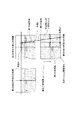
- FIG. 10 shows a schematic diagram of an outline of a cut line forming mechanism used to form a cut line in the RTP system.
- This cut line forming mechanism is formed by a cut line forming means having a cutting member for forming a cut line in the optical film laminate, and the position and the cut line of the preceding formed cut line are formed.
- a cut line formation position confirmation means for confirming the amount of deviation from the position to be formed.
- the cut line formation position confirmation means includes an image pickup means 1 that captures an image in a range including a part of a side edge of the optical film laminate on the upstream side of the cut line formation means, and a downstream side of the cut line formation means.
- Imaging means 2 for capturing an image of a range including a part of the side edge of the optical film laminate and a part of the preceding score line, and a control means for processing these images to generate correction information including.
- the side edge of the optical film laminate and the position of a part of the preceding cut line in the photographed image, and the optical film laminate set in the image The position at which the cut line is formed based on the deviation information (the deviation amounts indicated as distances ⁇ , ⁇ 1, and ⁇ 2 in FIG. 10) between the reference line that defines the feed direction and the reference line that is orthogonal to the reference line. Correction information is generated.
- the position at which the score line is formed refers to the position of the score line relative to the longitudinal direction of the optical film laminate (hereinafter referred to as “longitudinal direction formation position”) and the cut relative to the side edge of the optical film laminate.
- correction of the position at which the score line is formed refers to correction of the longitudinal direction formation position and angle of the score line. .
- the trajectory of the cutting member of the cut line forming means is corrected, and a cut line is formed in the optical film laminate.
- optical display devices have been reduced in size, thickness, and frame size.
- medium-sized or small-sized portable terminals such as smartphones and tablet-type terminals are rapidly spreading in the market.
- higher bonding accuracy between the panel member and the optical film sheet can be realized as compared with the large-sized optical display device for TV.
- One method for improving the bonding accuracy is to use a sheet having a higher right-angle accuracy of the four corners (that is, a higher squareness) as the sheet of the optical film.
- the conventional cut line forming mechanism used in the RTP system is extremely useful as a main technique for converting a manufacturing system of a large-sized optical display device for television use from an individual pasting system to an RTP system. there were.
- the conventional score line forming mechanism has a problem that it is difficult to obtain a sheet of an optical film having a higher squareness.
- the score line forming means for forming the score line and the imaging means constituting the score line forming position confirming means for confirming the position of the formed score line are mutually connected. They were installed independently, and their relative positional relationship was not related at all. Therefore, even when the trajectory of the cutting member of the score line forming means is corrected using the correction information generated based on the shift amount obtained from the information acquired by the score line forming position confirmation means, There is a problem that an error in the position where the score line is formed is likely to occur, and the crossing angle between the score line and the side edge portion may deviate from a right angle.
- the conventional score line formation mechanism a part of the score line at the position where the position information of the two side edge portions on one side of the optical film laminate intersects the side edge portion and the preceding score line.
- the correction information is generated and the formation position of the cut line is confirmed from the position information only. For this reason, even when the crossing angle between the side edge portion and the cut line from the right angle is large, it may not be reliably captured.
- a measurement error occurs due to the deflection or vibration of the optical film when detecting the preceding cut line, or the optical film is bent at the position where the cut line is formed. There was a problem that the cut line formation position was likely to change due to vibration.
- the conventional cut line forming mechanism uses an optical film particularly used for medium-sized and small-sized optical display devices. It has been difficult to form a score line that achieves the accuracy required for the sheet. In the case of a sheet of an optical film used for a medium-sized or small-sized liquid crystal display device, the influence on the bonding accuracy due to a decrease in the squareness resulting from such a problem is significant as compared with a large-sized liquid crystal display device.
- the present invention is capable of forming a score line that can be continuously formed in an optical film laminate so that the direction of the score line is exactly perpendicular to the side edge of the optical film laminate.
- An object is to provide an apparatus and a method for forming a score line.
- an optical film laminate in which at least a long web-like optical film and a long web-like carrier film are laminated via an adhesive layer, and the longitudinal direction of the optical film laminate
- a score line forming device for continuously forming a perpendicular score line in the width direction from a surface opposite to a carrier film to a depth reaching at least the surface of an adhesive layer.
- the score line forming device includes a score line forming means, a first detection means for detecting a first portion at one side edge of the optical film laminate, and a first detection means in the feed direction of the optical film laminate. 2nd detection means which detects the 2nd part of the side edge part which is arrange
- the score line forming apparatus further includes moving means, and the moving means maintains the predetermined relative positional relationship between the score line forming means, the first detection means, and the second detection means. It can be moved while.
- the predetermined relative positional relationship can be determined based on the shape of the panel member to which the sheet of optical film formed between the cutting line and the preceding cutting line is bonded.
- the score line forming apparatus has a control unit, and the control unit includes a first straight line obtained from the position information of the first part and the position information of the second part, and the optical film laminate. Based on the angle with the reference line that defines the feed direction, the driving of the moving means can be controlled so that the direction of the cut line is perpendicular to the side edge of the optical film laminate.
- the position information of the first part may be the coordinates of one point selected from above the first part
- the position information of the second part may be the coordinates of one point selected from above the second part.
- the first straight line can be a straight line connecting these points.
- the second detection means further detects a part of one preceding score line that is a predetermined distance away from the position of the score line formed by the score line forming means. Can do.
- the score line forming apparatus may further include third detection means for detecting another part different from the aforementioned part of the preceding score line.
- the third detecting means is moved by the moving means while maintaining a predetermined relative positional relationship together with the score line forming means, the first detecting means, and the second detecting means.
- the control means controls the drive of the moving means so that the direction of the score line is perpendicular to the side edge of the optical film laminate, and then the first straight line and a part of the preceding score line.
- the position information of a part of the preceding cutting line may be the coordinates of one point selected from the part, and the position information of the other part may be the point selected from the part.
- the second straight line can be a straight line connecting these points.
- the moving means includes a cut line forming means, a first detection means, a second detection means, a support portion that integrally supports the third detection means, and a cut line forming position.
- Support unit drive that drives the support unit so that the optical film laminate moves upstream or downstream in the feed direction and the crossing angle between the direction of the score line and the side edge of the optical film laminate changes. And a mechanism.
- the support part is provided between the first and second struts provided in parallel in the width direction of the optical film laminate, the girder part that is passed between the first and second struts and supports the score line forming means, It can have.
- the support unit driving mechanism includes a first driving unit for moving the first column to the upstream or downstream side in the feeding direction of the optical film laminate, and the second column to the upstream or downstream side in the feeding direction.
- a second drive unit for moving the first drive unit, a first connection unit for connecting the first drive unit and the first support column, and a second connection unit for connecting the second drive unit and the second support column. And a connecting portion.
- Each of the first and second connecting portions feeds the optical film laminate while each of the first and second support columns rotates relative to the corresponding one of the first and second drive portions.
- One of the first and second connecting portions is arranged in a lateral direction in which the relative positional relationship between the support column and the drive unit is orthogonal to the feed direction. It is configured to change freely.
- the control device controls each of the first and second drive units so that the movement direction and the movement amount of each of the first and second support columns are the same, thereby enabling the
- the control device is arranged so that the forming position moves upstream or downstream in the feeding direction of the optical film laminate, and the moving direction of each of the first and second support columns is reversed or the moving amount is different.
- the support unit driving mechanism further includes a third driving unit for moving the column connected to the other of the first and second connecting units in a direction orthogonal to the feeding direction.
- the position of the cut line and / or the position of the previous cut line is at one or both of the position of the cut line and / or the position of the previous cut line. It is preferable to further have one or a plurality of pressing members for pressing the optical film laminate so as not to move.
- Another aspect of the present invention uses a score line forming means on an optical film laminate in which at least a long web-like optical film and a long web-like carrier film are laminated via an adhesive layer, Cut line formation for continuously forming a cut line in the width direction perpendicular to the longitudinal direction of the optical film laminate from a surface opposite to the carrier film to a depth reaching at least the surface of the adhesive layer
- Cut line formation for continuously forming a cut line in the width direction perpendicular to the longitudinal direction of the optical film laminate from a surface opposite to the carrier film to a depth reaching at least the surface of the adhesive layer.
- This method detects the 1st part in one of the side edge parts of an optical film layered product using the 1st detection means, and it is the 1st seeing in the feed direction of an optical film layered product.
- a second detection step of detecting a second portion of the optical film laminate located on the downstream side of the first portion using the second detection means arranged on the downstream side of the detection means.
- the method further includes a moving step, and in the moving step, a first straight line obtained from the position information of the first part and the position information of the second part, and a reference for determining the feeding direction of the optical film laminate. Based on the angle with the line, the cut line formation position, the position of the first detection means, and the second position so that the direction of the cut line is perpendicular to the side edge of the optical film laminate.
- the position of the detecting means moves while maintaining a predetermined relative positional relationship.
- the position information of the first part may be the coordinates of one point selected from above the first part
- the position information of the second part may be the coordinates of one point selected from above the second part.
- the first straight line can be a straight line connecting these points.
- the predetermined relative positional relationship can be determined based on the shape of the panel member to which the sheet of optical film formed between the cutting line and the preceding cutting line is bonded.
- the second detecting step may further include a step of detecting a part of one preceding cut line that is separated from the formation position of the cut line by a predetermined distance.
- the method further uses a third detection means that is moved while maintaining a predetermined relative positional relationship together with the score line forming means, the first detection means, and the second detection means. It may further include a third detection step of detecting another portion different from the preceding portion of the preceding score line.
- the method further includes forming the score line, the first detection means, the second detection means, and the third detection so that the direction of the score line is perpendicular to the side edge of the optical film laminate.
- the optical system having one preceding cutting line as one edge
- a defective site identifying step of identifying a sheet of film as a defective site can be included.
- the position information of a part of the preceding cutting line may be the coordinates of one point selected from the part, and the position information of the other part may be the point selected from the part.
- the second straight line can be a straight line connecting these points.
- the cut line forming step includes a cut line forming position, a first detecting means position, a second detecting means position, and a third detecting means position on the upstream side in the feed direction or
- the process of moving to a downstream side and the process of moving so that the crossing angle of the direction of a cutting line and the said side edge part of the said optical film laminated body may change shall be included.
- the method includes a cut line formation position and / or a preceding cut position at either or both of the cut line formation position and / or one preceding cut line position.
- the method may further include pressing the optical film laminate so that the position of the line does not move.
- an optical film sheet having a higher squareness with two cut lines and two side edges as four sides on a carrier film.
- an optical film sheet By using such an optical film sheet, it becomes possible to further improve the bonding accuracy between the optical film sheet and the panel member, and to manufacture an optical display device corresponding to a smaller and narrower bezel.
- FIG. 1 is a schematic perspective view showing a score line forming apparatus according to an embodiment of the present invention. It is a schematic diagram for demonstrating the operation
- the apparatus and method for forming a score line according to the present invention provides a continuous cut line for defining a plurality of optical film sheets continuously supported on a long web-shaped carrier film in the optical film laminate. Can be used to form an image, and is particularly suitable for use in RTP systems for manufacturing medium and small optical displays. If the score line forming apparatus according to the present invention is used, the direction of the score line can be made perpendicular to the side edge of the optical film.
- the optical film sheet between the score lines continuously formed by the score line forming apparatus and method according to the present invention is supported on the long web-like carrier film and bonded to the panel member. After being sent to the position and peeled off from the long web-like carrier film together with the pressure-sensitive adhesive layer, it can be bonded to the panel member with high accuracy by the pressure-sensitive adhesive layer.
- a long web-like optical system is used in the previous process of the score line forming apparatus.
- a support device for mounting a roll of film laminate, a feeding device for continuously feeding the optical film laminate from the roll, a reader for reading encoded defect information recorded in advance on the optical film laminate, and a film feed speed A device such as a speed adjusting device for adjustment can be provided.
- the optical film laminate that has passed through these devices is fed into a score line forming device.
- an optical film laminated body is sent out to a post process from a score line formation apparatus.
- a speed adjusting device for adjusting the film feed speed
- an exclusion device for removing the optical film sheet having defects from the long web-like carrier film
- an optical film having no defects can be provided.
- Devices such as a laminating device for peeling the sheet from the long web-like carrier film and laminating the sheet on the panel member, and a winding drive device for winding the long web-like carrier film can be provided.
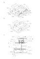
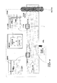
- FIG. 1 is a schematic side view showing a mechanism for forming a score line including a score line forming apparatus 1 according to an embodiment of the present invention.
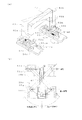
- FIG. 2 is a schematic perspective view showing the score line forming apparatus 1 according to one embodiment of the present invention.
- the optical film laminate PL (indicated by a two-dot chain line in FIG. 2) is sent in the direction indicated by the arrow in the figure. This direction is the direction when the web of the optical film laminate PL is fed in the original direction determined in the apparatus without meandering or skewing, and is referred to as “feeding direction” as described above.
- feeding direction A direction orthogonal to the feed direction is referred to as a “lateral direction”.
- the score line forming apparatus 1 includes a score line forming means 10 for forming a score line, detection means 20, 22, 24 for detecting side edges and score lines of the optical film laminate PL, and a score line. It has the moving means 30 which moves the formation means 10 and the detection means 20, 22, and 24 integrally, and the control means 100 which controls operation
- the optical film laminate PL on which the score line is formed in the score line forming device 1 is a long web-shaped optical film OP and a length bonded to the long web-shaped optical film OP via the adhesive layer A. It can be set as the laminated body containing the long web-like carrier film C.
- the long web-like optical film OP may be a single layer film or a multilayer film in which two or more types of optical films (for example, a polarizer and a retardation film) are bonded.
- the optical film laminate PL is prepared as a roll R having a width corresponding to one of the long side and the short side of the panel member.
- the optical film laminate PL fed from the roll R is cut through a film driving means D such as a feed roller for feeding out the optical film laminate PL, a speed adjusting means S such as a dancer roll for adjusting the film feed speed, and the like. It is sent to the stranded wire forming device 1.
- a cut line is formed on the pedestal 17 by the cut line forming means 10 in the optical film laminate fed to the cut line forming apparatus 1.
- the score line extends from the surface opposite to the carrier film C to the depth reaching at least the surface of the pressure-sensitive adhesive layer A (that is, the boundary surface between the carrier film C and the pressure-sensitive adhesive layer A). Formed in the direction.
- the optical film laminate PL is sent by a predetermined distance downstream in the feed direction, and the next score line is formed.
- This predetermined feeding distance corresponds to the other of the long side and the short side of the panel member to which the sheet PS of the optical film laminate is bonded.
- the cut line formed by the cut line forming means 10 and positioned on the pedestal 17 is a cut line CL1 (indicated by a one-dot chain line in FIG. 2), and the feed direction of the cut line CL1 A cut line located on the downstream side is defined as a preceding cut line CL2 (indicated by a dotted line in FIG. 2).
- the cut line forming means 10 of the cut line forming apparatus 1 includes a cutting member 11, a cutting member drive motor 12 for driving the cutting member 11, a feed screw 13 and a drive motor 14 for moving the cutting member 11 up and down, and The guide 15 and the drive motor 16 for moving the cutting member 11 in the lateral direction can be included.
- the cut line forming means 10 operates to form the cut line CL1 in the optical film PL under the control of the control means 100 as shown in FIG.
- the drive motor 14 operates to rotate the feed screw 13 so that the cutting member 11 descends to a predetermined position
- the cutting member drive motor 12 Operates to rotate the cutting member 11, and the drive motor 16 operates to move the cutting member 11 in the lateral direction.
- the cutting member 11 is preferably a disc-shaped blade, but is not limited to this, and other means such as a laser cutter can also be used.
- Each of the drive motors in the cut line forming means 10 is more preferably a servo motor so that the cut line can be formed with higher accuracy.
- the drive motor used in each part of the cut line forming apparatus 1 of the present embodiment similarly realizes the accuracy required for forming the cut line, and the accuracy of drive control of each part by the drive motor It is more preferable to use a servo motor that can further increase the power.
- the position of the cut line CL1 formed by the cut line forming means 10, that is, the feed direction forming position and the forming angle of the cut line CL1 is corrected using the correction information.
- the correction information is generated based on the position of the side edge in the width direction of the optical film laminate PL detected by the detection means and the position of the preceding cutting line CL2.
- the detection means includes at least three detection means, that is, a first detection means 20, a second detection means 22, and a third detection means.
- the detection means 24 can be used.
- the detection means 20, 22, and 24 are more preferably an image pickup means that captures an image in a predetermined range using a camera and illumination.
- the present invention is not limited to this, and for example, a laser type or an ultrasonic type An edge sensor such as can also be used.
- an imaging unit is used as the detection unit.
- the first detection means 20 can take an image of the first part E1, which is a part having a length, on at least one side edge of the optical film laminate PL. As shown in FIG. 2, the first portion E1 of the side edge portion photographed by the first detection means 20 is a position including the intersection of the side edge portion of the optical film laminate PL and the cut line CL1. More preferably, it is a part of the side edge portion. However, the first portion E1 photographed by the first detection means 20 is not limited to the position shown in FIG. 2, and any one portion on the upstream side in the feed direction from the position of the preceding cutting line CL2. If it is. The image including the first portion E1 is sent to the control means 100.
- the second detection means 22 is arranged on the downstream side of the first detection means in the feed direction of the optical film laminate PL.
- the second detection means 22 includes an intersection of the side edge and the preceding cutting line CL2 at the side edge on the same side as the first portion photographed by the first detection means 20.
- An image including the second portion E2 that is a portion having a height can be taken.
- the image by the second detection means 22 also includes a portion CL2-1 having the length of the cut line CL2 (see FIG. 7).
- the detected image including the second part E2 and the part CL2-1 of the cut line CL2 is sent to the control means 100.
- the third detection unit 24 captures an image including any other part CL2-2 having a length different from the part CL2-1 of the cut line CL2 captured by the second detection unit 22. (See FIG. 7).
- the portion CL2-2 to be photographed is the intersection of the side edge and the preceding cut line CL2 at the side edge opposite to the side edge to be photographed by the first and second detection means. It is more preferable that it is a part including.
- the photographed image including the other part CL2-2 of the cut line CL2 is sent to the control device 100.
- a first reference line and a second reference line are set in the images acquired by the first, second, and third detection means 20, 22, and 24, as will be described later with reference to FIG.
- the This setting is performed when the relative positional relationship between each of the detection means 20, 22, 24 and the score line forming means 10 is determined in advance (which will be described below in the description of the moving means). be able to.
- the first reference line is optical when it is assumed that the optical film laminate PL is sent to the cut line forming device 1 so as to coincide with the feeding direction determined in the device without meandering or skewing. It is a line parallel to the side edge portion that will be present in the image when the film laminate PL is photographed. That is, the first reference line determines the feeding direction of the optical film laminate.
- the second reference line is sent to the cut line forming device 1 so that the optical film laminate PL does not meander or skew, and coincides with the feed direction determined in the device, and the optical film laminate PL
- the optical film laminate PL is This is a line parallel to the preceding cut line that will be present in the image when it is taken.
- the second reference line defines the direction of the preceding cutting line.
- the first reference line and the second reference line are orthogonal to each other.
- the first and second reference lines may be set at any position in the image. For example, the first and second reference lines may be set so as to pass through the center point in the image.
- the amount of deviation between the first reference line and a part of the side edge portion photographed by the first and second detection means 20 and 22 is obtained.
- correction information is generated based on the amount of deviation, and using the correction information, the direction of the score line CL1 formed by the score line forming means 10 is the direction of the optical film laminate PL. It is controlled to be perpendicular to the side edge.
- the cut line forming angle is inspected based on the amount of deviation between the second reference line and a part of the cut line photographed by the third detection means 24. Details of the generation of the shift amount and the correction information and the inspection of the formation angle will be described later.
- the number of detection means shown in FIG. 2 is the minimum necessary for solving the problems of the present invention, and in order to further improve the detection accuracy, one or more detection means are further provided as a score line forming device. 1 may be provided.
- the score line forming apparatus 1 may include a fourth detection unit and a fifth detection unit.
- the fourth detection unit detects, for example, a part of the side edge portion of the optical film laminate PL between the first detection unit 20 and the second detection unit 22.
- a 5th detection means detects a part of side edge part of the optical film laminated body PL in the feed direction downstream of the 2nd detection means 22, for example.
- the position where the cut line CL1 is formed can be corrected based on the shift amount between the side edge and the cut line and the reference line.
- the correction of the position at which the cut line CL1 is formed is performed using the correction information generated based on the shift amount, and the angle with respect to the side edge portion of the track on which the cutting means 11 travels, and the cut line formation as necessary This is realized by changing the position of the means 10 in the feed direction.
- the score line forming means 10 can be moved by the moving means 30.
- the means for forming the score line and the means for detecting the position of the score line are installed independently of each other. There was a problem that it was difficult to form a score line that achieves the right-angle accuracy required for an optical film sheet used in a small optical display device.
- each of the detection means for detecting the side edge and the cut line of the optical film laminate actually sent to the cut line forming apparatus, and the cut line When the relative positional relationship with the cut line forming means to be formed is determined in advance and the cut line forming means is moved based on the shift amount between the side edge and the cut line and the reference line
- Each of the detection means and the score line forming means are configured to move in a state in which the relative positional relationship is maintained.
- the moving unit 30 includes a support portion 40 that integrally supports the score line forming unit 10 and the first to third detection units 20, 22, and 24. And a support part drive mechanism 50 that moves the support part 40 using the correction information generated based on the shift amount.
- the support portion 40 of the moving means 30 includes a downward U-shaped main frame 42 and an arm 44, as shown in FIG.
- the main frame 42 is passed between the first support column 48a and the second support column 48b provided in parallel in the horizontal direction, and the first and second support columns 48a, 48b above the optical film laminate PL, And a girder 43 to which the travel guide 15 of the score line forming means 10 is attached.
- the arm 44 extends from one of the first and second struts 48a and 48b (the second strut 48b in FIG.
- the first detection means 20 is provided on an arm 45 that extends in the lateral direction from the middle of the arm 44.
- the second and third detection means 22 and 24 are provided on the arm 46 extending in the lateral direction from the end of the arm 44 further extending downstream from the position of the arm 45 in the feed direction.
- it is necessary that the angle between the longitudinal direction of the beam portion 43 and the arm 44 and the angle between the arm 44 and the arm 45 and the arm 46 are configured at right angles. .
- connection position between the arm 44 and the main frame 42 is not limited to the second support column 48b, and may be, for example, the end 43b of the beam portion 43 or the first support column 48a. Further, when the main frame 42 moves when correcting the position where the cut line is formed, the arm 44 does not bend due to vibration during the movement (that is, the cut line forming means 10 and the arm 44 are detected).
- the relative position between the means 20, 22, and 24 is preferably not changed, and is preferably configured with a high-strength member and structure.
- each of the score line forming means and the detection means may be supported by a separate frame, and a drive unit corresponding to each of the score line forming means and each of the detection means may be provided separately.
- a predetermined relative positional relationship between the score line forming means and each of the detection means is determined by the control means.
- Each drive unit may be controlled so as to move while maintaining the above.
- the relative positional relationship between each of the detection means 20, 22, 24 and the score line forming means 10 is based on the shape of the panel member to which the optical film sheet is bonded, for example, as follows. It is preferable that it is predetermined.
- a panel member having alignment marks is prepared.
- the alignment marks are marks arranged at the four corners of the panel member for alignment with various members in the manufacturing process of the optical display device.
- the position of the alignment mark serves as a reference for determining the relative positional relationship between the detection means 20, 22, and 24.
- a panel member is arranged on the score line forming apparatus 1 so that each of the alignment marks falls within the respective imaging range of the detection means 20, 22, 24.
- each position of the detection means is corrected so that each alignment mark and each corresponding center of the imaging range overlap. More preferably, each position of the detection means is corrected using, for example, a drive motor such as a servo motor provided on the arms 45 and 46.
- a drive motor such as a servo motor provided on the arms 45 and 46.
- the support unit drive mechanism 50 is configured to be able to move the support unit 40.
- the support unit drive mechanism 50 includes a first drive unit 51a and a second drive unit 51b, a third drive unit 52, and first, second, and third drive units and a support unit.
- the first connecting portion 53a and the second connecting portion 53b that connect to 40 may be included.
- the constituent elements to which “a” is attached are sent when the optical film laminate PL is viewed from above (that is, from above the paper surface of FIG. 2).
- the component that is located on the right side in the direction and that is marked with “b” similarly indicates the component that is located on the left side in the feed direction.
- the first and second drive units 51a and 51b are provided in parallel in the horizontal direction, and as shown in FIGS. 2 and 3A, the drive motors 51ma and 51mb, and these drive motors, respectively. Feed screws 51sa and 51sb rotated by the nuts, nut members 51na and 51nb which are screwed into these feed screws to convert the rotational motion of the feed screws into linear motion, and feed screws on the opposite side of the drive screw to the drive motor. Bearings 51ja and 51jb that support the end of the shaft.
- the second drive part 51b can have the same structure as that shown in FIG. Or it can also have the structure which made the structure shown by Fig.3 (a) symmetrical in the horizontal direction.
- the third drive unit 52 is provided on one side of the first and second drive units 51a and 51b. As shown in FIGS. 2 and 4A, the third drive unit 52 includes a drive motor 52m, a feed screw 52s rotated by the drive motor, and a nut member that converts the rotational motion of the feed screw into linear motion. 52n and a bearing 52j that supports the end portion of the feed screw on the opposite side of the feed screw with respect to the drive motor.
- the first drive part 51a and the first support column 48a of the main frame 42 in the support part 40 are connected by a first connection part 53a.
- the second drive unit 51b and the third drive unit 52 are connected to the second support column 48b of the main frame 42 by the second connection unit 53b.
- the first connecting portion 53a includes a first feed direction movable table 54a, a first lateral direction movable table 55a, and a first bearing 59a.
- the second connecting portion 53b includes a second feed direction movable table 54b, a second lateral direction movable table 55b, and a second bearing 59b.
- the first and second feed direction movable tables 54a and 54b have nut members 51na and 51nb attached to their lower surfaces, respectively, by driving the drive motors 51ma and 51mb to rotate the feed screws 51sa and 51sb. Via the nut members 51na and 51nb, it can move freely in the direction of the arrow shown in FIG. 3A (the feeding direction of the optical film laminate PL). With such a configuration, it is possible to accurately control the movement amounts of the first and second feed direction movable tables 54a and 54b.
- traveling guides 70a and 70b are attached to the lower surfaces of the first and second feed movable tables 54a and 54b, and the traveling guides 70a and 70b are parallel to the feed screws 52sa and 52sb on the support base of the apparatus 1.
- the third feed direction movable table 54a, 54b (in this embodiment, the second feed direction movable table 54b in this embodiment) is placed on the third feed direction movable table 54a, 54b.
- a drive motor 52m and a bearing 52j of the drive unit 52 are attached.
- a nut member 52n of the third drive unit 52 is attached to the lower surface of the second laterally movable table 55b. Therefore, the second laterally movable table 55b drives the drive motor 52m to rotate the feed screw 52s, thereby causing the arrow direction (feed direction and the direction shown in FIG. It can move freely in the orthogonal direction. With such a configuration, the movement amount of the second laterally movable table 55b can be accurately controlled.
- a travel guide 72b is attached to the lower surface of the second laterally movable table 55b, and the travel guide 72b is disposed on the second feed direction movable table 54b in parallel with the feed screw 52s. It is slidably held on the top. With this configuration, the movement amount of the second laterally movable table 55b can be controlled with higher accuracy. There may be a plurality of traveling guides and traveling rails corresponding to the second laterally movable table 55b.
- a traveling guide 72a is attached to the lower surface of the first laterally movable table 55a as shown in FIG. 4B, and the traveling guide 72a is movable in the first feed direction. It is slidably held on a travel guide rail 73a attached on the table 54a. Since the first laterally movable table 55a is not connected to a drive unit such as the third drive unit 52, the first laterally movable table 55a can freely move in the lateral direction with respect to the first feed direction movable table 54a. it can.
- the first and second laterally movable tables 55a and 55b and the first and second columns 48a and 48b of the main frame 43 are connected via first and second bearings 59a and 59b, respectively. Yes.
- the first and second support columns 48a and 48b are arranged so that the shaft centers of the two race rings of the first and second bearings 59a and 59b are aligned.
- a relative turning movement can be performed with respect to the first and second laterally movable tables.
- the support part 40 moves by the support part drive mechanism 50 configured as described above.
- the first and second movable tables 54a and 54b that is, the first and second support columns 48a and 48b
- the beam part 42 of the support part 40 is fed in the feeding direction of the optical film laminate PL via the first and second support columns 48a and 48b connected to the first and second connection parts 53a and 53b, respectively. It moves to the upstream side or the downstream side. In this way, it is possible to control the longitudinal formation position of the score line formed by the blade 11 moving along the girder portion 42.
- the first and second connecting portions 53a and 53b are controlled.
- the first and second movable tables 54a and 54b that is, the first and second support columns 48a and 48b
- a quadrangular surface formed by the line connecting the trajectory of the cutting member 11 and the center of the visual field of each of the detection means 20, 22, 24 (hereinafter referred to as “swivel plane”).
- the drive motors 51ma and 51mb are controlled so that the rotation directions of the drive motors 51ma and 51mb are reversed and the rotation speed of the drive motor 51ma is larger than the rotation speed of the drive motor 51mb.
- the horizontal position of the second horizontal movable table 55b is fixed, and the second movable table 55b is configured to be freely movable in the horizontal direction.
- One laterally movable table 55a moves upstream or downstream in the feed direction while the track draws an arc.
- the turning plane moves from the center line in the feed direction of the optical film laminate PL to the second laterally movable table 55b according to the difference between the rotational speed of the drive motor 51ma and the rotational speed of the drive motor 51mb. It will turn around any nearby position.
- the drive motors 51ma, 51mb When it is desired to turn the turning plane around any position closer to the first laterally movable table 55a than the center line in the feeding direction of the optical film laminate PL, the drive motors 51ma, 51mb
- the drive direction of the drive motors 51ma and 51mb is controlled so that the rotation direction is reversed and the rotation speed of the drive motor 51mb is larger than the rotation speed of the drive motor 51ma, and the lateral direction of the first laterally movable table 55a
- the drive of the drive motor 52m may be controlled so that the trajectory of the second laterally movable table 55b draws an arc without moving the position.
- the bending or vibration of the optical film laminate is suppressed at the position where the score line is formed by the score line forming means 10 or at the position of the preceding score line.
- at the position where the cut line CL1 is formed and / or the position of the preceding cut line CL2 using a pressing member that holds the optical film laminate, It is preferable to suppress bending and vibration of the film laminate.
- the pressing member is provided before and after the cutting line CL ⁇ b> 1, before and after the preceding cutting line CL ⁇ b> 2, or both when viewed in the longitudinal direction of the optical film laminate. It is preferable.
- the form and type of the pressing member are not particularly limited as long as they can suppress bending and vibration of the optical film laminate.
- a film clamp or a combination of a pressing roll and a holding roll can be used as the pressing member.
- the film clamp can be switched between an open state and a closed state by being driven by a clamp drive mechanism, and sandwiches both sides of the optical film laminate over the entire width direction in the clamp closed state. .
- FIG. 1 shows that shows that can suppress bending and vibration of the optical film laminate.
- the combination of the pressing roll and the holding roll includes a holding roll that presses the position of the score line from the surface on the carrier film side over the entire width direction of the optical film laminate, By using a pair of pressing rolls that press the front and back from the surface opposite to the carrier film, bending and vibration of the optical film laminate can be suppressed.
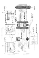
- Control of the operation of each means, component, and mechanism of the score line forming apparatus 1 according to the embodiment of the present invention, and the calculation and processing necessary for these operations are shown in FIG. 104 and the control means 100 having the information processing apparatus 102.
- Data used to control the operation of each means, component, and mechanism of the cut line forming device 1 for example, information on the position of the side edge of the optical film laminate PL, information on the position of the cut line
- Various data such as deviation amounts of these positions from the reference position
- data necessary for calculation and processing, calculation results and processing results, and the like are stored in the storage device 104 included in the control device 100 and necessary.
- writing / reading is performed between the storage device 104 and the information processing device 102.
- the contents of control by the control means 100 are shown in FIG.
- FIG. 6 is a schematic flowchart showing a process of forming a score line by the score line forming apparatus 1.
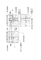
- FIG. 7 is a schematic diagram for explaining the outline of the correction method of the cut line forming position by the cut line forming apparatus 1.
- FIG. 8 is a schematic diagram for explaining a method for obtaining the inclination angle of the optical film laminate PL, and
- FIG. 9 is a schematic diagram for explaining a method for confirming the angle of the formed score line. .
- the relative positional relationship between the score line forming means 10 in the support portion 40 and the first, second and third detection means 20, 22, 24 is determined. (S1 in FIG. 6).
- the method for determining the positional relationship is as described in connection with the explanation of the moving means 30 described above.
- the first and second reference lines are set in the image by each detection means.
- the process of forming the score line by the score line forming apparatus 1 starts when the optical film laminate PL is fed out by the film driving means D from the roll R of the optical film laminate PL (s2).
- the fed optical film laminate PL is sent to the score line forming apparatus 1 through, for example, the speed adjusting means S (s3 to s5).
- a cut line having a depth reaching from the surface opposite to the carrier film C to at least the surface of the pressure-sensitive adhesive layer A is formed in the fed optical film laminate PL.
- the optical film laminate PL is sent to the downstream side in the feed direction by a predetermined distance, and the next cut.
- the pressing member is used at the formation position of the cut line CL1 and / or the position of the preceding cutting line CL2, it is preferable to operate the pressing member at this point (s6).
- one side edge portion of the optical film laminate PL (in this embodiment, as shown in FIG. 7, the left side edge portion in the feed direction of the optical film laminate PL) is the first side edge portion.
- the first detection means 20 detects the first portion E1 (FIG. 7) at the side edge
- the second detection means 22 detects the second portion E2 (FIG. 7) at the side edge.
- the detection of the first and second portions E1 and E2 can be performed, for example, by searching for the brightness of the entire image acquired by the detection means and recognizing a place having a large contrast difference as a line segment.
- the detected first and second portions E1 and E2 with any point in the image (usually, but not limited to, the center of the image) as the origin.
- the coordinates of an arbitrary point in each of these are calculated. One of these points is the intersection of the origin axis passing through the origin in the image and orthogonal to the first reference line, and the first and second portions E1 and E2 (in FIG. 8, coordinates (0, y1) and ( The point indicated as 0, y3) is preferred.
- the coordinates are stored in the storage device 104 as position information of the first and second portions E1 and E2.
- the cut line CL2 that precedes the optical film laminate PL that has stopped feeding is detected by the second detection means 22.
- the second detection means 22 can detect a part CL2-1 of the preceding cutting line CL2.
- the detection of the part CL2-1 of the cut line CL2 can be performed using, for example, a contrast difference, similarly to the detection of the first and second parts E1 and E2 of the side edge.
- FIG. 8 on any part CL2-1 of the detected cut line CL2, with any point in the image (usually, but not limited to, the center of the image) as the origin.
- the coordinates of one arbitrary point of are calculated. This point is shown as the intersection (the coordinates (x1, 0) in FIG.
- the coordinates are stored in the storage device 104 as position information of a part CL2-1 of the cut line CL2.
- an angle between a first reference line and a straight line connecting one point on the first portion E1 and one point on the second portion E2 (this is referred to as a first straight line), that is, optical
- the inclination angle of the side edge portion from the feeding direction of the film laminate PL is calculated.
- a distance ⁇ 1 between the first portion E1 and the first reference line is obtained.
- the distance ⁇ 1 is obtained from the position information of the first portion E1 and the position information of the first reference line.
- the position information of the first reference line is the coordinates of the intersection of the origin axis line that passes through the origin in the image and is orthogonal to the first reference line, and the first reference line (in FIG. 8, coordinates (0, y2)). As shown).
- the distance ⁇ 2 between the second part E2 and the first reference line is obtained from the position information of the second part E2 and the position information of the first reference line.
- the position information of the first reference line can be the coordinates of the intersection of the first reference line and the origin axis line that passes through the origin in the image and is orthogonal to the first reference line.
- the information processing means 102 calculates the deviation amount from the position of the part CL2-1 of the cut line and the position of the second reference line. calculate. As shown in FIG. 7, from the position information of the part CL2-1 of the preceding cutting line CL2 and the position information of the second reference line, between the part CL2-1 and the second reference line The distance ⁇ 1 is obtained, and the distance ⁇ 1 can be used as the amount of deviation.
- the position information of the second reference line is the coordinates of the intersection of the origin axis line passing through the origin in the image and orthogonal to the second reference line, and the second reference line (in FIG. 8, coordinates (x2, 0)) As shown).
- This distance ⁇ 1 is stored in the storage means as data for generating correction information of the longitudinal formation position of the score line.
- step s9 it is determined whether or not the aforementioned inclination angle ⁇ and / or distance ⁇ 1 exists.
- correction information is calculated from the calculated inclination angle ⁇ and distance ⁇ 1 in steps s10 and s11, and the drive motors 51ma and 51mb are driven according to the correction information.
- the correction information includes the rotation speed and rotation direction of the drive motors 51ma and 51mb of the first and second drive sections 51a and 51b, and the rotation speed and rotation of the drive motor 52m of the third drive section 52 as necessary.
- the formation position of the cut line, the position of the first detection means, the position of the second detection means, and the position of the third detection means are cut while maintaining a predetermined relative positional relationship.
- the moving means 30 is controlled so that the trajectory of the blade 11 of the line forming means 10 is corrected.
- steps s7 to s11 are repeated as necessary, and when the inclination angle ⁇ and / or the distance ⁇ 1 no longer exist, it is cut in step s12. Formation of the lead-in line CL1 is performed.
- the cut line CL1 may be formed after step 14 described later, that is, after the confirmation of the formation angle of the preceding cut line CL2.
- steps s13 and s14 an inspection is performed as to whether or not the crossing angle formed by the preceding cutting line CL2 and the side edge of the optical film laminate PL is deviated from a right angle.
- This inspection is performed as follows.
- the cutting line CL2 that precedes the optical film laminate PL is detected by the third detection means 24.
- the third detection means 24 detects a portion CL2-2 that is different from the portion CL2-1 detected by the second detection means 22.
- the detection of another portion CL2-2 can be performed using, for example, a contrast difference in the same manner as the detection of the portion CL2-1 of the preceding cutting line.
- a portion CL2-2 of the detected cut line CL2 The coordinates of an arbitrary point are calculated.
- One arbitrary point is, for example, the intersection (the coordinate (x3, 0 in FIG. 9) of the origin axis line passing through the origin in the image and orthogonal to the second reference line and the detected cut line portion CL2-2. ).
- the coordinates are stored in the storage device 104 as position information of a part CL2-2 of the cut line CL2.
- the angle ⁇ ′ between the preceding cutting line CL2 and the side edge of the optical film laminate PL is obtained, and the deviation angle ⁇ between the angle ⁇ ′ and the right angle is smaller than a predetermined allowable value. Judgment is made. This permissible value can be determined according to the accuracy of perpendicularity required for the optical film sheet in order to achieve the required bonding accuracy with the panel member.
- the angle ⁇ ′ is determined by a straight line (this is called a second straight line) connecting one point on a part CL2-1 of the preceding cutting line CL2 and one point on CL2-2, and a side edge portion. The angle of intersection formed.
- the first straight line and the first reference line are parallel to each other, and the above-mentioned distance ⁇ 1 is zero. It can be obtained by using the distance ⁇ 2 between one point on another part CL2-2 of the line CL2 and the second reference line.
- the distance ⁇ 2 is obtained from the position information of the part CL2-2 of the cut line CL2 and the position information of the second reference line.
- the position information of the second reference line is the coordinates of the intersection of the origin axis passing through the origin in the image and orthogonal to the second reference line, and the second reference line (in FIG. 9, coordinates (x2, 0)) As shown).
- the angle ⁇ is calculated by the following equation.
- the angle ⁇ is stored in the storage device 104.
- the angle ⁇ When the angle ⁇ is larger than a predetermined allowable value, it is formed between the cut line CL1 and the cut line CL2 of the optical film having the leading cut line CL2 as a leading edge. Sheet and an optical film sheet having one leading cutting line CL2 as a trailing edge, that is, one preceding cutting line CL2 and one preceding cutting line (cut lines CL1 to 2). The sheet between the two preceding cutting lines) is identified as a defective portion. The identification information indicating that these sheets are defective parts and the position information thereof are stored in the storage device. If the angle ⁇ is smaller than a predetermined tolerance, these sheets are identified as normal parts.
- the optical film laminate PL is sent again by a predetermined distance downstream in the feeding direction, and the steps from s5 to s15 are repeated.
- the sheet identified as a defective part in steps s13 and s14 is peeled off from the carrier film C in the subsequent process based on the position information, and is discharged from the process without being bonded to the panel member. become.
- part can be bonded together with a panel member in the bonding process with a panel member.
Landscapes
- Life Sciences & Earth Sciences (AREA)
- Forests & Forestry (AREA)
- Engineering & Computer Science (AREA)
- Mechanical Engineering (AREA)
- Polarising Elements (AREA)
- Nonmetal Cutting Devices (AREA)
- Control Of Cutting Processes (AREA)
Priority Applications (2)
| Application Number | Priority Date | Filing Date | Title |
|---|---|---|---|
| KR1020147009823A KR101493476B1 (ko) | 2012-05-18 | 2013-05-16 | 절입선형성장치 및 절입선형성방법 |
| CN201380026021.4A CN104302455B (zh) | 2012-05-18 | 2013-05-16 | 切割线形成装置以及切割线形成方法 |
Applications Claiming Priority (2)
| Application Number | Priority Date | Filing Date | Title |
|---|---|---|---|
| JP2012113913A JP5501404B2 (ja) | 2012-05-18 | 2012-05-18 | 切込線形成装置及び切込線形成方法 |
| JP2012-113913 | 2012-05-18 |
Publications (1)
| Publication Number | Publication Date |
|---|---|
| WO2013172404A1 true WO2013172404A1 (ja) | 2013-11-21 |
Family
ID=49583807
Family Applications (1)
| Application Number | Title | Priority Date | Filing Date |
|---|---|---|---|
| PCT/JP2013/063633 Ceased WO2013172404A1 (ja) | 2012-05-18 | 2013-05-16 | 切込線形成装置及び切込線形成方法 |
Country Status (5)
| Country | Link |
|---|---|
| JP (1) | JP5501404B2 (enExample) |
| KR (1) | KR101493476B1 (enExample) |
| CN (1) | CN104302455B (enExample) |
| TW (1) | TWI468783B (enExample) |
| WO (1) | WO2013172404A1 (enExample) |
Cited By (3)
| Publication number | Priority date | Publication date | Assignee | Title |
|---|---|---|---|---|
| CN112310243A (zh) * | 2020-09-16 | 2021-02-02 | 韩华新能源(启东)有限公司 | 适用于切割不良电池片串焊时的定位方法及串焊方法 |
| CN115070843A (zh) * | 2022-07-06 | 2022-09-20 | 浙江金科胶粘制品有限公司 | 一种泡棉胶带的切割装置 |
| CN116466521A (zh) * | 2023-06-12 | 2023-07-21 | 广州鲜柚智能科技有限公司 | 一种用于快速安装电视背光光学膜片的结构 |
Families Citing this family (8)
| Publication number | Priority date | Publication date | Assignee | Title |
|---|---|---|---|---|
| JP6478599B2 (ja) * | 2014-12-03 | 2019-03-06 | 日東電工株式会社 | 切込線形成方法及び切込線形成装置 |
| CN106003172B (zh) * | 2016-05-20 | 2018-07-24 | 湖北三江航天江河化工科技有限公司 | 一种自动裁片机及其裁片方法 |
| CN106078858B (zh) * | 2016-07-20 | 2018-02-23 | 东莞市美士富实业有限公司 | 一种塑料板切槽机构 |
| CN106116132A (zh) * | 2016-08-11 | 2016-11-16 | 东旭科技集团有限公司 | 基板玻璃饵料掰断控制系统及控制方法 |
| KR102174949B1 (ko) * | 2019-03-12 | 2020-11-05 | 조주안 | 필름 절단 장치 및 필름 절단 방법 |
| CN110434932B (zh) * | 2019-07-20 | 2021-02-26 | 杭州爱科科技股份有限公司 | 太阳能薄膜柔性组件自动修边方法 |
| JP6931413B1 (ja) * | 2020-10-09 | 2021-09-01 | 日東電工株式会社 | 切込線形成装置及び切込線形成方法 |
| JP7100386B2 (ja) * | 2020-10-28 | 2022-07-13 | 日高精機株式会社 | カットオフ装置及び熱交換器用フィンの製造装置 |
Citations (4)
| Publication number | Priority date | Publication date | Assignee | Title |
|---|---|---|---|---|
| JP2006334715A (ja) * | 2005-06-01 | 2006-12-14 | Fujifilm Holdings Corp | 積層体フイルムのハーフカット方法及び装置 |
| JP2007283456A (ja) * | 2006-04-19 | 2007-11-01 | Dainippon Printing Co Ltd | シート材切断装置 |
| WO2009128115A1 (ja) * | 2008-04-15 | 2009-10-22 | 日東電工株式会社 | 光学フィルム積層体ロールならびにその製造方法および装置 |
| JP2010078843A (ja) * | 2008-09-25 | 2010-04-08 | Nitto Denko Corp | 光学フィルム巻取り原反及びその製造方法 |
Family Cites Families (8)
| Publication number | Priority date | Publication date | Assignee | Title |
|---|---|---|---|---|
| JPS51122882A (en) * | 1975-04-21 | 1976-10-27 | Hitachi Metals Ltd | Paper cutter control |
| JP3995839B2 (ja) * | 1999-08-10 | 2007-10-24 | 住友化学株式会社 | 光学フィルム積層体の製造設備 |
| US6520056B1 (en) * | 1999-08-26 | 2003-02-18 | Rockwell Collins, Inc. | Method and apparatus for cutting optical films having precision alignment of optical axes with optical film edges |
| JP2003149164A (ja) * | 2001-11-15 | 2003-05-21 | Nippon Spindle Mfg Co Ltd | 透明若しくは半透明膜の検査方法及び剥離装置 |
| JP4293537B2 (ja) * | 2003-11-27 | 2009-07-08 | 日東電工株式会社 | 積層シートの切削加工方法と積層シートと光学素子と画像表示装置 |
| JP5123501B2 (ja) * | 2005-12-13 | 2013-01-23 | 株式会社ホンダロック | 板ガラス切断方法および装置 |
| JP5248052B2 (ja) * | 2006-10-11 | 2013-07-31 | 日東電工株式会社 | 光学フィルムを有するシート状製品の欠点検査装置、その検査データ処理装置、その切断装置及びその製造システム |
| KR101054387B1 (ko) * | 2010-06-10 | 2011-08-04 | 닛토덴코 가부시키가이샤 | 액정패널 제조장치에 있어서의 필름시트와 직사각형 패널과의 위치맞춤 방법 |
-
2012
- 2012-05-18 JP JP2012113913A patent/JP5501404B2/ja active Active
-
2013
- 2013-05-16 KR KR1020147009823A patent/KR101493476B1/ko active Active
- 2013-05-16 WO PCT/JP2013/063633 patent/WO2013172404A1/ja not_active Ceased
- 2013-05-16 CN CN201380026021.4A patent/CN104302455B/zh active Active
- 2013-05-16 TW TW102117377A patent/TWI468783B/zh active
Patent Citations (4)
| Publication number | Priority date | Publication date | Assignee | Title |
|---|---|---|---|---|
| JP2006334715A (ja) * | 2005-06-01 | 2006-12-14 | Fujifilm Holdings Corp | 積層体フイルムのハーフカット方法及び装置 |
| JP2007283456A (ja) * | 2006-04-19 | 2007-11-01 | Dainippon Printing Co Ltd | シート材切断装置 |
| WO2009128115A1 (ja) * | 2008-04-15 | 2009-10-22 | 日東電工株式会社 | 光学フィルム積層体ロールならびにその製造方法および装置 |
| JP2010078843A (ja) * | 2008-09-25 | 2010-04-08 | Nitto Denko Corp | 光学フィルム巻取り原反及びその製造方法 |
Cited By (6)
| Publication number | Priority date | Publication date | Assignee | Title |
|---|---|---|---|---|
| CN112310243A (zh) * | 2020-09-16 | 2021-02-02 | 韩华新能源(启东)有限公司 | 适用于切割不良电池片串焊时的定位方法及串焊方法 |
| CN112310243B (zh) * | 2020-09-16 | 2022-07-26 | 韩华新能源(启东)有限公司 | 适用于切割不良电池片串焊时的定位方法及串焊方法 |
| CN115070843A (zh) * | 2022-07-06 | 2022-09-20 | 浙江金科胶粘制品有限公司 | 一种泡棉胶带的切割装置 |
| CN115070843B (zh) * | 2022-07-06 | 2024-04-19 | 浙江金科胶粘制品有限公司 | 一种泡棉胶带的切割装置 |
| CN116466521A (zh) * | 2023-06-12 | 2023-07-21 | 广州鲜柚智能科技有限公司 | 一种用于快速安装电视背光光学膜片的结构 |
| CN116466521B (zh) * | 2023-06-12 | 2023-12-15 | 广州鲜柚智能科技有限公司 | 一种用于快速安装电视背光光学膜片的结构 |
Also Published As
| Publication number | Publication date |
|---|---|
| JP2013240841A (ja) | 2013-12-05 |
| CN104302455B (zh) | 2016-04-06 |
| TW201411233A (zh) | 2014-03-16 |
| KR20140063811A (ko) | 2014-05-27 |
| TWI468783B (zh) | 2015-01-11 |
| KR101493476B1 (ko) | 2015-02-13 |
| CN104302455A (zh) | 2015-01-21 |
| JP5501404B2 (ja) | 2014-05-21 |
Similar Documents
| Publication | Publication Date | Title |
|---|---|---|
| JP5501404B2 (ja) | 切込線形成装置及び切込線形成方法 | |
| JP4503691B1 (ja) | 液層表示素子の連続製造方法及び装置 | |
| WO2011155036A1 (ja) | 表示パネル製造装置におけるフィルムシートと矩形パネルとの位置合せ方法 | |
| CN104023898B (zh) | 激光照射装置、光学构件贴合体的制造装置、激光照射方法以及光学构件贴合体的制造方法 | |
| JP5791018B2 (ja) | 光学表示デバイスの生産システム及び生産方法 | |
| TW201506501A (zh) | 用於附接薄膜的系統 | |
| JP2009016416A (ja) | 可撓性回路基板の製造方法および製造装置 | |
| JP5022507B1 (ja) | 製品パネルの連続製造方法、検出システム及び検出方法 | |
| JP2015045820A (ja) | フィルム貼合装置、光学表示デバイスの生産システム及び光学表示デバイスの生産方法 | |
| CN104541318B (zh) | 光学显示器件的生产系统以及光学显示器件的生产方法 | |
| CN104541317B (zh) | 光学显示器件的生产方法以及光学显示器件的生产系统 | |
| CN107009724A (zh) | 连续制造光学显示装置的装置及方法 | |
| JP6931413B1 (ja) | 切込線形成装置及び切込線形成方法 | |
| KR20190085467A (ko) | 광학 표시 패널의 연속 검사 방법 및 연속 검사 장치, 그리고 광학 표시 패널의 연속 제조 방법 및 연속 제조 시스템 | |
| JP6356891B1 (ja) | 光学的表示装置の積層体を製造する方法および装置 | |
| CN104520917B (zh) | 光学显示器件的生产方法以及光学显示器件的生产系统 | |
| JP2007094043A (ja) | 薄板の位置決め方法および薄板の位置決め装置 |
Legal Events
| Date | Code | Title | Description |
|---|---|---|---|
| WWE | Wipo information: entry into national phase |
Ref document number: 201380026021.4 Country of ref document: CN |
|
| 121 | Ep: the epo has been informed by wipo that ep was designated in this application |
Ref document number: 13791251 Country of ref document: EP Kind code of ref document: A1 |
|
| ENP | Entry into the national phase |
Ref document number: 20147009823 Country of ref document: KR Kind code of ref document: A |
|
| NENP | Non-entry into the national phase |
Ref country code: DE |
|
| 122 | Ep: pct application non-entry in european phase |
Ref document number: 13791251 Country of ref document: EP Kind code of ref document: A1 |