WO2013171883A1 - 電池の製造方法 - Google Patents
電池の製造方法 Download PDFInfo
- Publication number
- WO2013171883A1 WO2013171883A1 PCT/JP2012/062686 JP2012062686W WO2013171883A1 WO 2013171883 A1 WO2013171883 A1 WO 2013171883A1 JP 2012062686 W JP2012062686 W JP 2012062686W WO 2013171883 A1 WO2013171883 A1 WO 2013171883A1
- Authority
- WO
- WIPO (PCT)
- Prior art keywords
- battery
- resin particles
- separator layer
- active material
- negative electrode
- Prior art date
Links
Images


Classifications
-
- H—ELECTRICITY
- H01—ELECTRIC ELEMENTS
- H01M—PROCESSES OR MEANS, e.g. BATTERIES, FOR THE DIRECT CONVERSION OF CHEMICAL ENERGY INTO ELECTRICAL ENERGY
- H01M50/00—Constructional details or processes of manufacture of the non-active parts of electrochemical cells other than fuel cells, e.g. hybrid cells
- H01M50/40—Separators; Membranes; Diaphragms; Spacing elements inside cells
- H01M50/46—Separators, membranes or diaphragms characterised by their combination with electrodes
-
- H—ELECTRICITY
- H01—ELECTRIC ELEMENTS
- H01M—PROCESSES OR MEANS, e.g. BATTERIES, FOR THE DIRECT CONVERSION OF CHEMICAL ENERGY INTO ELECTRICAL ENERGY
- H01M10/00—Secondary cells; Manufacture thereof
- H01M10/05—Accumulators with non-aqueous electrolyte
- H01M10/052—Li-accumulators
-
- H—ELECTRICITY
- H01—ELECTRIC ELEMENTS
- H01M—PROCESSES OR MEANS, e.g. BATTERIES, FOR THE DIRECT CONVERSION OF CHEMICAL ENERGY INTO ELECTRICAL ENERGY
- H01M50/00—Constructional details or processes of manufacture of the non-active parts of electrochemical cells other than fuel cells, e.g. hybrid cells
- H01M50/40—Separators; Membranes; Diaphragms; Spacing elements inside cells
- H01M50/403—Manufacturing processes of separators, membranes or diaphragms
-
- H—ELECTRICITY
- H01—ELECTRIC ELEMENTS
- H01M—PROCESSES OR MEANS, e.g. BATTERIES, FOR THE DIRECT CONVERSION OF CHEMICAL ENERGY INTO ELECTRICAL ENERGY
- H01M50/00—Constructional details or processes of manufacture of the non-active parts of electrochemical cells other than fuel cells, e.g. hybrid cells
- H01M50/40—Separators; Membranes; Diaphragms; Spacing elements inside cells
- H01M50/409—Separators, membranes or diaphragms characterised by the material
- H01M50/411—Organic material
- H01M50/414—Synthetic resins, e.g. thermoplastics or thermosetting resins
- H01M50/417—Polyolefins
-
- H—ELECTRICITY
- H01—ELECTRIC ELEMENTS
- H01M—PROCESSES OR MEANS, e.g. BATTERIES, FOR THE DIRECT CONVERSION OF CHEMICAL ENERGY INTO ELECTRICAL ENERGY
- H01M50/00—Constructional details or processes of manufacture of the non-active parts of electrochemical cells other than fuel cells, e.g. hybrid cells
- H01M50/40—Separators; Membranes; Diaphragms; Spacing elements inside cells
- H01M50/409—Separators, membranes or diaphragms characterised by the material
- H01M50/443—Particulate material
-
- H—ELECTRICITY
- H01—ELECTRIC ELEMENTS
- H01M—PROCESSES OR MEANS, e.g. BATTERIES, FOR THE DIRECT CONVERSION OF CHEMICAL ENERGY INTO ELECTRICAL ENERGY
- H01M50/00—Constructional details or processes of manufacture of the non-active parts of electrochemical cells other than fuel cells, e.g. hybrid cells
- H01M50/40—Separators; Membranes; Diaphragms; Spacing elements inside cells
- H01M50/489—Separators, membranes, diaphragms or spacing elements inside the cells, characterised by their physical properties, e.g. swelling degree, hydrophilicity or shut down properties
- H01M50/491—Porosity
-
- H—ELECTRICITY
- H01—ELECTRIC ELEMENTS
- H01M—PROCESSES OR MEANS, e.g. BATTERIES, FOR THE DIRECT CONVERSION OF CHEMICAL ENERGY INTO ELECTRICAL ENERGY
- H01M10/00—Secondary cells; Manufacture thereof
- H01M10/05—Accumulators with non-aqueous electrolyte
- H01M10/058—Construction or manufacture
-
- H—ELECTRICITY
- H01—ELECTRIC ELEMENTS
- H01M—PROCESSES OR MEANS, e.g. BATTERIES, FOR THE DIRECT CONVERSION OF CHEMICAL ENERGY INTO ELECTRICAL ENERGY
- H01M4/00—Electrodes
- H01M4/02—Electrodes composed of, or comprising, active material
- H01M4/13—Electrodes for accumulators with non-aqueous electrolyte, e.g. for lithium-accumulators; Processes of manufacture thereof
- H01M4/139—Processes of manufacture
-
- Y—GENERAL TAGGING OF NEW TECHNOLOGICAL DEVELOPMENTS; GENERAL TAGGING OF CROSS-SECTIONAL TECHNOLOGIES SPANNING OVER SEVERAL SECTIONS OF THE IPC; TECHNICAL SUBJECTS COVERED BY FORMER USPC CROSS-REFERENCE ART COLLECTIONS [XRACs] AND DIGESTS
- Y02—TECHNOLOGIES OR APPLICATIONS FOR MITIGATION OR ADAPTATION AGAINST CLIMATE CHANGE
- Y02E—REDUCTION OF GREENHOUSE GAS [GHG] EMISSIONS, RELATED TO ENERGY GENERATION, TRANSMISSION OR DISTRIBUTION
- Y02E60/00—Enabling technologies; Technologies with a potential or indirect contribution to GHG emissions mitigation
- Y02E60/10—Energy storage using batteries
-
- Y—GENERAL TAGGING OF NEW TECHNOLOGICAL DEVELOPMENTS; GENERAL TAGGING OF CROSS-SECTIONAL TECHNOLOGIES SPANNING OVER SEVERAL SECTIONS OF THE IPC; TECHNICAL SUBJECTS COVERED BY FORMER USPC CROSS-REFERENCE ART COLLECTIONS [XRACs] AND DIGESTS
- Y02—TECHNOLOGIES OR APPLICATIONS FOR MITIGATION OR ADAPTATION AGAINST CLIMATE CHANGE
- Y02P—CLIMATE CHANGE MITIGATION TECHNOLOGIES IN THE PRODUCTION OR PROCESSING OF GOODS
- Y02P70/00—Climate change mitigation technologies in the production process for final industrial or consumer products
- Y02P70/50—Manufacturing or production processes characterised by the final manufactured product
Definitions
- the present invention relates to a battery manufacturing method including an electrode plate in which a separator layer is integrally formed on an active material layer.
- a battery using an electrode plate (positive electrode plate or negative electrode plate) in which a separator layer is integrally formed on an active material layer (positive electrode active material layer or negative electrode active material layer) is known.
- the separator layer is composed of, for example, resin particles and a binder that is interposed between the resin particles to bind them.
- This separator layer is formed by applying a dispersion liquid in which resin particles, a binder, and the like are dispersed on an active material layer to form an undried separator layer, and heating and drying the separator layer.
- the binder also covers the surface of the active material particles (positive electrode active material particles or negative electrode active material particles) constituting the active material layer.
- Patent Document 1 is given as a prior art of a battery including an electrode plate in which a separator layer is integrally formed on an active material layer.
- One embodiment of the present invention for solving the above problems is an electrode having an active material layer made of active material particles, and a separator layer formed integrally with the active material layer and made of thermoplastic resin particles.
- a method for producing a battery comprising a plate, wherein a coating step in which a dispersion liquid in which the resin particles are dispersed is applied on the active material layer to form an undried separator layer;
- a heating and drying step of drying by heating to form the separator layer, and the heating and drying step is a temperature within a surface melting temperature range in which the surface portion does not melt but the surface portion does not melt, It is a manufacturing method of the battery which is a process of heating and drying the undried separator layer.
- this battery manufacturing method it is possible to manufacture a battery in which the internal resistance of the battery is reduced by eliminating or reducing the binder, while strengthening the binding between the resin particles.
- the dispersion liquid does not include a binder that is interposed between the resin particles and binds the resin particles.
- a method of manufacturing a battery that is a dispersion is preferable.
- the resin particles may be polyethylene battery particles.
- the battery manufacturing method according to any one of the above, wherein the resin particles have an average particle diameter of 1.0 to 5.0 ⁇ m.
- 1 is a perspective view of a lithium ion secondary battery according to an embodiment. It is a longitudinal cross-sectional view of the lithium ion secondary battery which concerns on embodiment. It is an expanded view of the electrode body which concerns on embodiment and shows the state which accumulated the positive electrode plate and the negative electrode plate mutually.
- 1 is a perspective view of a negative electrode plate according to an embodiment. It is an enlarged sectional photograph of a separator layer concerning an embodiment. Relates to the embodiment, it is a partially enlarged sectional view of the separator layer that drawing the photograph of FIG. It is a DSC curve of a resin particle according to the embodiment. It is explanatory drawing which concerns on embodiment and shows the manufacturing process of a negative electrode plate.
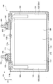
- FIG. 1 and 2 show a lithium ion secondary battery 100 (hereinafter also simply referred to as a battery 100) according to the present embodiment.
- FIG. 3 shows a state where the wound electrode body 120 constituting the battery 100 is developed.
- FIG. 4 shows the negative electrode plate 131.
- the thickness direction BH, the width direction CH, and the height direction DH of the battery 100 are defined as the directions shown in FIGS. 1 and 2 will be described as the upper side of the battery 100, and the lower side will be described as the lower side of the battery 100.
- the battery 100 is a square sealed battery mounted on a vehicle such as a hybrid vehicle or an electric vehicle, or a battery-operated device such as a hammer drill.
- the battery 100 includes a rectangular parallelepiped battery case 110, a flat wound electrode body 120 accommodated in the battery case 110, a positive terminal 150 and a negative terminal 160 supported by the battery case 110, and the like. (See FIGS. 1 and 2).
- a non-aqueous electrolyte solution 117 is held in the battery case 110.
- the battery case 110 is made of metal (specifically, aluminum).
- the battery case 110 includes a box-shaped case main body member 111 that is open only on the upper side, and a case lid member 113 that is welded so as to close the opening 111h of the case main body member 111 (see FIG. 1 and FIG. 1). (See FIG. 2).
- a non-returnable safety valve 113v is provided in the case lid member 113 in the vicinity of the center in the longitudinal direction (the width direction CH of the battery 100). Further, in the vicinity of the safety valve 113v, a liquid injection hole 113h used for injecting the electrolytic solution 117 into the battery case 110 is provided.
- the liquid injection hole 113h is hermetically sealed with a sealing member 115.
- a positive terminal (positive terminal member) 150 and a negative terminal that extend from the inside of the battery case 110 to the outside. (Negative electrode terminal member) 160 is fixed. Specifically, these terminals 150 and 160 are connected to the case lid via insulating members 155 and 165 made of resin together with bolts 153 and 163 for fastening connection terminals outside the battery, such as bus bars and crimp terminals. It is fixed to the member 113.
- the electrode body 120 is housed in the battery case 110 in a state where the electrode body 120 is laid down so that its axis (winding axis) is parallel to the width direction CH of the battery 100 (see FIG. 2).
- a belt-like positive electrode plate 121 and a belt-like negative electrode plate 131 are overlapped with each other (see FIG. 3), wound around an axis, and compressed into a flat shape.
- a part of an exposed portion 122m, which will be described later, of the positive electrode plate 121 protrudes in a spiral shape on one side AC in the axial direction (upward in FIG. 3, left in FIG. 2).
- Terminal member) 150 is connected (welded).
- An exposed portion 132m, which will be described later, of the negative electrode plate 131 protrudes in a spiral shape on the other side AD (downward in FIG. 3, rightward in FIG. 2) in the axial direction.
- Member 160 welding).
- the positive electrode plate 121 has a strip-like positive electrode foil 122 made of aluminum as a core material. A part of the positive electrode foil 122 in the width direction (upward in FIG. 3) is an exposed portion 122m extending in a strip shape in the longitudinal direction (left-right direction in FIG. 3). On the other hand, a positive electrode active material layer (positive electrode mixture layer) 123 extending in a strip shape in the longitudinal direction is formed on both main surfaces of portions other than the exposed portion 122m (downward in FIG. 3). The positive electrode active material layer 123 is formed of positive electrode active material particles, a conductive material, and a binder.
- lithium-cobalt-nickel-manganese composite oxide particles (specifically, LiCo 1/3 Ni 1/3 Mn 1/3 O 2 ) are used as the positive electrode active material particles, and carbon black ( Specifically, acetylene black) is used as the binder, and polyvinylidene fluoride (PVDF) is used as the binder.
- carbon black Specifically, acetylene black
- PVDF polyvinylidene fluoride
- the negative electrode plate 131 (see FIGS. 3 and 4) has a strip-like negative electrode foil 132 made of copper as a core material.
- a part of the negative electrode foil 132 in the width direction FH (downward in FIG. 3) is an exposed portion 132m extending in a strip shape in the longitudinal direction EH (left-right direction in FIG. 3).
- negative electrode active material layers (negative electrode mixture layer, active material layer) 133 extending in a strip shape in the longitudinal direction EH are formed on both main surfaces of the portions other than the exposed portion 132m (upward in FIG. 3).
- a separator layer 141 extending in a strip shape in the longitudinal direction EH is integrally formed on the negative electrode active material layer 133.
- the negative electrode active material layer 133 is formed of negative electrode active material particles 135, a binder, and a thickener.
- graphite particles are used as the negative electrode active material particles 135, styrene butadiene rubber (SBR) is used as the binder, and carboxymethyl cellulose (CMC) is used as the thickener.
- SBR styrene butadiene rubber
- CMC carboxymethyl cellulose
- the separator layer 141 is a porous film having a thickness of 30 ⁇ m, does not include a binder, and is formed of thermoplastic resin particles 143 and a thickener 144. That is, as shown in the photograph of FIG. 5 and FIG. 6, the adjacent resin particles 143 are fused and joined three-dimensionally only by the surface portion 143 h, and three-dimensionally between these resin particles 143. A gap (hole) KG connected to is formed.
- the porosity Ca of this separator layer 141 is 35.4%.
- polyethylene (PE) particles which will be described later, are used as the thermoplastic resin particles 143
- CMC carboxymethyl cellulose
- the ratio between the resin particles 143 and the thickener 144 is 99.7: 0.3 by weight.
- thickener (CMC) 144 is believed to be deposited on the resin particles 143.
- the separator layer generally has a binder, for example, a fluororesin binder such as polyvinylidene fluoride (PVDF), polyvinyl fluoride (PVF), polytetrafluoroethylene (PTFE), styrene butadiene rubber ( Rubber-based binders such as SBR), nitrile rubber (NBR), and acrylic rubber (ACM) are used.
- a fluororesin binder such as polyvinylidene fluoride (PVDF), polyvinyl fluoride (PVF), polytetrafluoroethylene (PTFE), styrene butadiene rubber ( Rubber-based binders such as SBR), nitrile rubber (NBR), and acrylic rubber (ACM) are used.
- PVDF polyvinylidene fluoride
- PVF polyvinyl fluoride
- PTFE polytetrafluoroethylene
- Rubber-based binders such as SBR
- NBR nitrile rubber
- the resin particles 143 are spherical particles made of PE, and the average particle size is 2.5 ⁇ m.
- the average particle diameter was used the value of by laser diffraction and scattering particle ⁇ size distribution measuring method D50.
- the Nikkiso Co., Ltd. microtrack was used for the measurement of an average particle diameter.
- the resin particles 143 have thermal characteristics in which two endothermic peaks P1 and P2 appear, as can be seen from the differential scanning calorimetry (DSC) curve shown in FIG. That is, in DSC, the second peak P2 of the total melting heat shown when the entire resin particle 143 melts appears, and the surface portion 143h is not melted to the central portion 143g of the resin particle 143 in a lower temperature range.
- the peak temperature Tb of the first peak P1 is 62.7 ° C.
- the peak temperature Tc of the second peak P2 is 101.2 ° C.
- the negative electrode active material particles 135, the binder, and the thickener are dispersed in a solvent to prepare a negative electrode paste.
- natural graphite (negative electrode active material), SBR (binder) and CMC (thickener) are mixed, and slurry (negative electrode paste) is adjusted while adjusting the viscosity with a solvent (specifically water). Get.
- a strip-shaped negative electrode foil 132 made of copper is prepared.
- the negative electrode paste is applied to one main surface of the negative electrode foil 132 by a die coating method to form a strip-shaped negative electrode paste layer.
- the negative electrode paste layer is heated and dried with hot air while passing through the drying furnace to form the negative electrode active material layer 133.
- a negative electrode paste is applied to the opposite main surface of the negative electrode foil 132 to form a negative electrode paste layer (negative electrode active material layer coating step S1), and this is heated and dried to obtain a negative electrode active material.
- Layer 133 is formed (negative electrode active material layer heating and drying step S2).
- the negative electrode active material layer 133 is pressed with a pressure roll, and the negative electrode active material layer 133 is compressed in the thickness direction to increase its density (to a predetermined thickness).
- thermoplastic resin particles 143 and the thickener 144 are dispersed in a solvent to prepare a dispersion BS.
- PE particles (resin particles) 143 and CMC (thickener) 144 are mixed at a weight ratio of 99.7: 0.3 and dispersed in a solvent (specifically, water).
- a liquid BS is obtained.
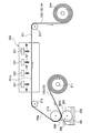
- the excessive dispersion liquid BS adhering to the surface 201 h of the gravure roll 201 is scraped off by the doctor blade 205. Then, an appropriate amount of the dispersion BS remaining on the surface 201 h of the gravure roll 201 is sequentially applied onto the negative electrode active material layer 133 on one main surface side of the negative electrode foil 132 unwound from the unwinding roll 211. The undried separator layer 141p is formed.
- the undried separator layer 141p is dried by heating to form the separator layer 141 (see FIG. 9).
- the negative electrode foil 132 on which the undried separator layer 141p and the negative electrode active material layer 133 are formed is conveyed by the rotation of the conveying rollers 213, 215, and 217, and is passed through the drying furnace 230.
- a plurality of hot air dryers 231 are installed in the drying furnace 230, and hot air NF at a temperature Ta (specifically, 62.0 ° C.) is sprayed from each hot air dryer 231 onto the undried separator layer 141p.
- the undried separator layer 141p is heated and dried to form the separator layer 141. Thereafter, the negative electrode foil 132 on which the separator layer 141 and the negative electrode active material layer 133 are formed is taken up by a take-up roll 219.
- the temperature Ta (specifically, 62.0 ° C.) is a surface melting temperature range TD (specifically, 52.7 to 72) that does not melt up to the central part 143g of the resin particles 143 but melts the surface part 143h. .7 ° C.).
- the surface melting temperature range TD is a range of Tb ⁇ 10.0 ° C. with respect to the peak temperature Tb (specifically 62.7 ° C.) of the surface melting heat.
- the above-described dispersion BS is applied on the negative electrode active material layer 133 on the opposite side to form an undried separator layer 141p (separator layer coating step S4). Thereafter, the undried separator layer 141p is heated and dried to form the separator layer 141 (separator layer heating and drying step S5). Thereby, the negative electrode plate 131 is formed (see FIG. 4).
- the positive electrode plate 121 is manufactured. That is, a strip-shaped positive electrode foil 122 made of aluminum is prepared. A positive electrode paste containing lithium / cobalt / nickel / manganese composite oxide particles (positive electrode active material particles), acetylene black (conductive material) and PVDF (binder) is formed on one main surface of the positive electrode foil 122. The positive electrode active material layer 123 is formed by applying and drying. Similarly, the positive electrode paste is applied to the opposite main surface of the positive electrode foil 122 and dried to form the positive electrode active material layer 123. Thereafter, the positive electrode active material layer 123 is compressed by a pressure roll to increase its density. Thereby, the positive electrode plate 121 is formed (see FIG. 3).
- the positive electrode plate 121 and the negative electrode plate 131 are overlapped with each other (see FIG. 3) and wound around the axis using a winding core.
- the electrode body 120 is formed by compressing it into a flat shape.
- a case lid member 113, a positive electrode terminal member 150, a negative electrode terminal member 160, and bolts 153 and 163 are prepared, and these are set in a mold for injection molding.
- the insulating members 155 and 165 are integrally formed by injection molding, and the positive terminal member (positive terminal) 150 and the negative terminal member (negative terminal) 160 are fixed to the case lid member 113.
- the positive electrode terminal 150 and the negative electrode terminal 160 are connected (welded) to the electrode body 120, respectively.
- the case body member 111 is prepared, the electrode body 120 is accommodated in the case body member 111, and the opening 111 h of the case body member 111 is closed with the case lid member 113.
- the case main body member 111 and the case lid member 113 are laser-welded (see FIGS. 1 and 2).
- the electrolytic solution 117 is injected into the battery case 110 from the injection hole 113h, and the injection hole 113h is hermetically sealed by the sealing member 115.
- the battery 100 is subjected to initial charging, aging, and various inspections. Thus, the battery 100 is completed.
- Example 1 the negative electrode plate 131 was manufactured by the manufacturing method according to the embodiment.
- the temperature Ta in the heat drying step S5 of the separator layer 141 is 62.0 ° C.
- Example 2 as shown in Table 1, the temperature Ta in the heating and drying step S5 was 57.0 ° C., which was 5.0 deg lower than that in Example 1, and the others were the same as in Example 1.
- Example 3 the temperature Ta in the heat drying step S5 was set to 67.0 ° C., which is 5.0 deg higher than that in Example 1, and the others were the same as in Example 1.
- the porosity Ca (%) was determined by the method described above.
- the "cracking test" of the separator layer was performed and the binding property of the resin particles 143 was evaluated. Specifically, each negative electrode plate was wound around a winding core having a diameter of 1 mm, 2 mm, or 3 mm. Then, the surface state of the separator layer is visually observed, and a sample in which no crack (crack) is generated in the separator layer is good (indicated by “ ⁇ ” in the table), and a sample in which the crack is generated is defective (in the table) (Indicated by “x”). These results are shown in Table 1.
- each separator layer according to Comparative Examples 3 and 4 had a low porosity Ca (27.7 to 30.2%).
- 10 and 11 show a separator layer according to Comparative Example 4.
- the reason why the porosity Ca is small in the separator layers according to Comparative Examples 3 and 4 is that the high temperature Ta (75.0) exceeding the surface melting temperature range TD (52.7 to 72.7 ° C.) in the heat drying step S5. Therefore, the resin particles 143 in the undried separator layer 141p melted not only the surface portion 143h but also the center portion 143g. For this reason, the resin particles 143 adjacent to each other are fused (see FIGS. 10 and 11). As a result, it is considered that the gap (hole) KG between the resin particles 143 is reduced and the porosity Ca is reduced.
- each separator layer according to Examples 1 to 3 and Comparative Examples 1 and 2 had a higher porosity Ca than each separator layer according to Comparative Examples 3 and 4 (35.1 to 35). .8%).
- the reason why the porosity Ca was increased in the separator layers according to Examples 1 to 3 was that the temperature Ta (57.0 ° C.) in the surface drying temperature range TD (52.7 to 72.7 ° C.) in the heat drying step S5. 62.0 ° C. or 67.0 ° C.), the resin particles 143 in the undried separator layer 141p did not melt up to the center part 143g, but only the surface part 143h melted. For this reason, the resin particles 143 adjacent to each other were fused together only at the surface portion 143h. As a result, it is considered that the gap (hole) KG between the resin particles 143 is increased and the porosity Ca is increased.
- the separator layer was not cracked.
- the heating and drying step S5 is performed at a temperature Ta (Examples 1 to 3) within the surface melting temperature range TD (52.7 to 72.7 ° C.), or a temperature Ta ( Since it was performed in Comparative Examples 3 and 4, the resin particles 143 in the undried separator layer 141p were melted at least at the surface portion 143h, and the adjacent resin particles 143 were fused together. For this reason, the binding force between the resin particles 143 is strong, and even when stress is generated when the negative electrode plate is wound around the winding core, the resin particles 143 are not separated from each other, and it is considered that the separator layer is not cracked.
- the heat drying step S5 is preferably performed within the surface melting temperature range TD (52.7 to 72.7 ° C.), and in particular, the peak temperature Tb (specifically 62. It can be seen that it is better to carry out within a range of Tb ⁇ 7.0 ° C. with respect to 7 ° C.).
- the surface melting temperature range TD (Tb ⁇ 10 with respect to the peak temperature Tb of the surface melting heat) in which the surface portion 143h does not melt but melts up to the central portion 143g of the resin particle 143.
- the separator layer 141 is formed by heating and drying the undried separator layer 141p at a temperature Ta within a range of 0.0 ° C.
- a separator layer 141 having a gap (vacancy) KG which led to a three-dimensional can be formed. Therefore, the binding agent contained in the separator layer 141 can be eliminated while the binding between the resin particles 143 is strengthened, and the battery 100 having a small battery internal resistance can be manufactured.
- the temperature Ta in the heat drying step is set within a range of Tb ⁇ 7.0 ° C. with respect to the peak temperature Tb of the heat of surface melting.
- the dispersion BS does not include a binder that is interposed between the resin particles 143 and binds the resin particles 143, the negative electrode active material particles 135 are not covered with the binder.
- a battery 100 having a particularly small battery internal resistance can be manufactured.
- the separator layer 141 with favorable tolerance with respect to the electrolyte solution 117 can be formed by using the resin particles 143 as PE particles. PE particles are easy to handle because of their low melting point. Further, by using resin particles 143 having an average particle size of 1.0 to 5.0 ⁇ m, gaps (holes) KG between the resin particles 143 can be formed in an appropriate size.
- the present invention is applied to the formation of the negative electrode plate 131, but the present invention may be applied to the formation of the positive electrode plate 121.
- the undried separator layer 141p is heated and dried in the heating and drying step S5 by blowing hot air NF on the undried separator layer 141p, but is not limited thereto.
- the undried separator layer 141p may be heated and dried using an IR heater, an IH heater, or the like.
- the PE particles are exemplified as the thermoplastic resin particles 143 constituting the separator layer 141, but the embodiment is not limited thereto.
- the thermoplastic resin particle material include polyethylene copolymer, polypropylene (PP), polypropylene copolymer, polyvinyl chloride (PVC), polystyrene (PS), polyvinyl acetate (PVAc), and polytetrafluoroethylene.
- PTFE acrylonitrile butadiene styrene resin
- ABS resin acrylonitrile butadiene styrene resin
- AS resin acrylic resin cage
- PA polyamide
- PA polyacetal
- PC polycarbonate
- PET polyethylene terephthalate
- PAI polyamideimide
- polyolefin resins such as polyethylene, polyethylene copolymer, polypropylene, and polypropylene copolymer are particularly preferable.
- the polyolefin resin has a melting point suitable as a material constituting the separator layer. That is, for some reason, when the temperature of the battery becomes higher than the upper limit temperature for battery operation (the temperature at which the electrolytic solution begins to change, for example, 60 ° C.), the separator layer quickly dissolves and its own gap (empty) This is because the battery can be shut down appropriately (stopping the battery reaction) by closing the hole.
- CMC is exemplified as the thickener 144 added to the dispersion BS for forming the separator layer 141, but the present invention is not limited to this.
- the thickener include water-soluble polymers such as methyl cellulose (MC) and polyvinyl alcohol (PVA).
- Lithium ion secondary battery 120 Electrode body 121 Positive electrode plate 131 Negative electrode plate (electrode plate) 132 Negative electrode foil 133 Negative electrode active material layer (negative electrode mixture layer, active material layer) 141 Separator layer 141p Undried separator layer 143 Resin particles 143h Surface portion 143g Center portion 144 Thickener BS Dispersion KG Gap (hole) NF Hot air P1 1st peak P2 2nd peak
Landscapes
- Chemical & Material Sciences (AREA)
- Chemical Kinetics & Catalysis (AREA)
- Electrochemistry (AREA)
- General Chemical & Material Sciences (AREA)
- Engineering & Computer Science (AREA)
- Manufacturing & Machinery (AREA)
- Materials Engineering (AREA)
- Secondary Cells (AREA)
- Battery Electrode And Active Subsutance (AREA)
- Cell Separators (AREA)
Abstract
Description
Ca={1-(ρ1/ρ2)}×100
次いで、実施形態に係る電池100の製造方法の効果を検証するために行った試験の結果について説明する。実施例1として、実施形態に係る製造方法により負極板131を製造した。この製造方法では、前述したように、セパレータ層141の加熱乾燥工程S5における温度Taが62.0℃である。また、実施例2では、表1に示すように、加熱乾燥工程S5における温度Taを、実施例1よりも5.0deg低い57.0℃とし、それ以外は実施例1と同様とした。また、実施例3では、加熱乾燥工程S5における温度Taを、実施例1よりも5.0deg高い67.0℃とし、それ以外は実施例1と同様とした。

120 電極体
121 正極板
131 負極板(電極板)
132 負極電極箔
133 負極活物質層(負極合剤層,活物質層)
141 セパレータ層
141p 未乾燥セパレータ層
143 樹脂粒子
143h 表面部
143g 中心部
144 増粘剤
BS 分散液
KG 隙間(空孔)
NF 熱風
P1 第1ピーク
P2 第2ピーク
Claims (6)
- 活物質粒子からなる活物質層と、
前記活物質層上に一体的に形成され、熱可塑性の樹脂粒子からなるセパレータ層と、を有する電極板を備える
電池の製造方法であって、
前記活物質層上に、前記樹脂粒子を分散させた分散液を塗布して、未乾燥セパレータ層を形成する塗工工程と、
前記未乾燥セパレータ層を加熱乾燥させて、前記セパレータ層を形成する加熱乾燥工程と、を備え、
前記加熱乾燥工程は、
前記樹脂粒子の中心部までは融解しないが表面部は融解する表面融解温度範囲内の温度で、前記未乾燥セパレータ層を加熱乾燥させる工程である
電池の製造方法。 - 請求項1に記載の電池の製造方法であって、
前記樹脂粒子は、
示差走査熱量測定において、前記樹脂粒子全体が融解する際に示す全体融解熱のピークのほか、これよりも低い温度域に、前記樹脂粒子の前記中心部までは融解しないが前記表面部が融解する際に示す表面融解熱のピークが現れる熱特性を有し、
前記表面融解温度範囲は、前記表面融解熱のピーク温度に対し±10.0℃の範囲である
電池の製造方法。 - 請求項2に記載の電池の製造方法であって、
前記加熱乾燥工程において前記未乾燥セパレータ層を加熱乾燥させる前記温度は、前記ピーク温度に対し±7.0℃の範囲内の温度である
電池の製造方法。 - 請求項1~請求項3のいずれか一項に記載の電池の製造方法であって、
前記分散液は、前記樹脂粒子同士の間に介在して前記樹脂粒子同士を結着させる結着剤を含まない結着剤無し分散液である
電池の製造方法。 - 請求項1~請求項4のいずれか一項に記載の電池の製造方法であって、
前記樹脂粒子は、ポリエチレン粒子である
電池の製造方法。 - 請求項1~請求項5のいずれか一項に記載の電池の製造方法であって、
前記樹脂粒子の平均粒径は、1.0~5.0μmである
電池の製造方法。
Priority Applications (6)
| Application Number | Priority Date | Filing Date | Title |
|---|---|---|---|
| PCT/JP2012/062686 WO2013171883A1 (ja) | 2012-05-17 | 2012-05-17 | 電池の製造方法 |
| JP2014515430A JP5874821B2 (ja) | 2012-05-17 | 2012-05-17 | 電池の製造方法 |
| CN201280073276.1A CN104335389A (zh) | 2012-05-17 | 2012-05-17 | 电池的制造方法 |
| EP12876981.7A EP2851974A4 (en) | 2012-05-17 | 2012-05-17 | METHOD FOR PRODUCING A CELL |
| US14/397,391 US20150086707A1 (en) | 2012-05-17 | 2012-05-17 | Method for manufacturing a battery |
| KR1020147031728A KR20150003313A (ko) | 2012-05-17 | 2012-05-17 | 전지의 제조 방법 |
Applications Claiming Priority (1)
| Application Number | Priority Date | Filing Date | Title |
|---|---|---|---|
| PCT/JP2012/062686 WO2013171883A1 (ja) | 2012-05-17 | 2012-05-17 | 電池の製造方法 |
Publications (1)
| Publication Number | Publication Date |
|---|---|
| WO2013171883A1 true WO2013171883A1 (ja) | 2013-11-21 |
Family
ID=49583325
Family Applications (1)
| Application Number | Title | Priority Date | Filing Date |
|---|---|---|---|
| PCT/JP2012/062686 WO2013171883A1 (ja) | 2012-05-17 | 2012-05-17 | 電池の製造方法 |
Country Status (6)
| Country | Link |
|---|---|
| US (1) | US20150086707A1 (ja) |
| EP (1) | EP2851974A4 (ja) |
| JP (1) | JP5874821B2 (ja) |
| KR (1) | KR20150003313A (ja) |
| CN (1) | CN104335389A (ja) |
| WO (1) | WO2013171883A1 (ja) |
Cited By (2)
| Publication number | Priority date | Publication date | Assignee | Title |
|---|---|---|---|---|
| WO2017138116A1 (ja) * | 2016-02-10 | 2017-08-17 | 株式会社日立製作所 | リチウムイオン電池およびその製造方法 |
| JP2018160340A (ja) * | 2017-03-22 | 2018-10-11 | トヨタ自動車株式会社 | 非水電解液二次電池用負極の製造方法、および非水電解液二次電池の製造方法 |
Families Citing this family (4)
| Publication number | Priority date | Publication date | Assignee | Title |
|---|---|---|---|---|
| JP6536524B2 (ja) | 2016-10-03 | 2019-07-03 | トヨタ自動車株式会社 | セパレータ一体電極板、及びこれを用いた蓄電素子 |
| CN107170955B (zh) * | 2017-05-26 | 2019-07-12 | 清华大学 | 一种可方便拆解回收的锂离子电池、制作方法及拆解回收方法 |
| JP7010183B2 (ja) * | 2018-09-11 | 2022-01-26 | トヨタ自動車株式会社 | 帯状電極板の製造方法、電池の製造方法及び電極板製造装置 |
| JP7131472B2 (ja) * | 2019-04-25 | 2022-09-06 | トヨタ自動車株式会社 | セパレータ付き電極板の製造方法及び電池の製造方法 |
Citations (3)
| Publication number | Priority date | Publication date | Assignee | Title |
|---|---|---|---|---|
| JPH04292856A (ja) * | 1991-03-20 | 1992-10-16 | Nippon Muki Co Ltd | 蓄電池用焼結式セパレータの製造法 |
| JP2000149906A (ja) | 1998-11-04 | 2000-05-30 | Mitsubishi Chemicals Corp | リチウム二次電池 |
| JP2001351616A (ja) * | 2000-06-05 | 2001-12-21 | Toyota Motor Corp | 電極の製造方法 |
Family Cites Families (14)
| Publication number | Priority date | Publication date | Assignee | Title |
|---|---|---|---|---|
| US2653986A (en) * | 1951-10-24 | 1953-09-29 | Owens Corning Fiberglass Corp | Battery plate separator |
| US2973398A (en) * | 1957-12-23 | 1961-02-28 | Ohmies Ltd | Method and apparatus for manufacturing battery separators |
| US3544384A (en) * | 1968-05-07 | 1970-12-01 | Tudor Ab | Method of making a laminated porous battery separator |
| US4144301A (en) * | 1972-09-25 | 1979-03-13 | The Secretary Of State For Defence In Her Britannic Majesty's Government Of The United Kingdom Of Great Britain And Northern Ireland | Separators for electrolytic cells |
| US4279979A (en) * | 1978-11-09 | 1981-07-21 | The Dexter Corporation | Nonwoven fibrous substrate for battery separator |
| CN1134078C (zh) * | 1995-08-28 | 2004-01-07 | 旭化成株式会社 | 新型电池及其制造方法 |
| US5948464A (en) * | 1996-06-19 | 1999-09-07 | Imra America, Inc. | Process of manufacturing porous separator for electrochemical power supply |
| JP2000340204A (ja) * | 1999-05-25 | 2000-12-08 | Mitsui Chemicals Inc | 電池用セパレーターおよびその製造方法、非水電解液二次電池 |
| WO2001091219A1 (en) * | 2000-05-22 | 2001-11-29 | Korea Institute Of Science And Technology | A lithium secondary battery comprising a porous polymer separator film fabricated by a spray method and its fabrication method |
| JP4498772B2 (ja) * | 2003-04-22 | 2010-07-07 | パナソニック株式会社 | アルカリ蓄電池とその製造法 |
| CN1918727A (zh) * | 2004-02-07 | 2007-02-21 | 株式会社Lg化学 | 用有机/无机复合多孔层涂覆的电极以及包括该电极的电化学装置 |
| DE102005042215A1 (de) * | 2005-09-05 | 2007-03-08 | Degussa Ag | Separator mit verbesserter Handhabbarkeit |
| KR20090111342A (ko) * | 2007-05-10 | 2009-10-26 | 히다치 막셀 가부시키가이샤 | 전기 화학 소자 및 그 제조방법 |
| PL2672546T3 (pl) * | 2009-03-09 | 2018-08-31 | Asahi Kasei Kabushiki Kaisha | Mikroporowata membrana poliolefinowa |
-
2012
- 2012-05-17 WO PCT/JP2012/062686 patent/WO2013171883A1/ja active Application Filing
- 2012-05-17 JP JP2014515430A patent/JP5874821B2/ja not_active Expired - Fee Related
- 2012-05-17 EP EP12876981.7A patent/EP2851974A4/en not_active Withdrawn
- 2012-05-17 CN CN201280073276.1A patent/CN104335389A/zh active Pending
- 2012-05-17 KR KR1020147031728A patent/KR20150003313A/ko not_active Application Discontinuation
- 2012-05-17 US US14/397,391 patent/US20150086707A1/en not_active Abandoned
Patent Citations (3)
| Publication number | Priority date | Publication date | Assignee | Title |
|---|---|---|---|---|
| JPH04292856A (ja) * | 1991-03-20 | 1992-10-16 | Nippon Muki Co Ltd | 蓄電池用焼結式セパレータの製造法 |
| JP2000149906A (ja) | 1998-11-04 | 2000-05-30 | Mitsubishi Chemicals Corp | リチウム二次電池 |
| JP2001351616A (ja) * | 2000-06-05 | 2001-12-21 | Toyota Motor Corp | 電極の製造方法 |
Non-Patent Citations (1)
| Title |
|---|
| See also references of EP2851974A4 |
Cited By (3)
| Publication number | Priority date | Publication date | Assignee | Title |
|---|---|---|---|---|
| WO2017138116A1 (ja) * | 2016-02-10 | 2017-08-17 | 株式会社日立製作所 | リチウムイオン電池およびその製造方法 |
| JP6227168B1 (ja) * | 2016-02-10 | 2017-11-08 | 株式会社日立製作所 | リチウムイオン電池およびその製造方法 |
| JP2018160340A (ja) * | 2017-03-22 | 2018-10-11 | トヨタ自動車株式会社 | 非水電解液二次電池用負極の製造方法、および非水電解液二次電池の製造方法 |
Also Published As
| Publication number | Publication date |
|---|---|
| JPWO2013171883A1 (ja) | 2016-01-07 |
| EP2851974A1 (en) | 2015-03-25 |
| JP5874821B2 (ja) | 2016-03-02 |
| CN104335389A (zh) | 2015-02-04 |
| US20150086707A1 (en) | 2015-03-26 |
| EP2851974A4 (en) | 2015-11-04 |
| KR20150003313A (ko) | 2015-01-08 |
Similar Documents
| Publication | Publication Date | Title |
|---|---|---|
| JP5874821B2 (ja) | 電池の製造方法 | |
| CN102576875B (zh) | 电极板、二次电池和电极板的制造方法 | |
| KR101942254B1 (ko) | 리튬 이온 2차 전지용 전극의 제조 방법 | |
| JP5708526B2 (ja) | 二次電池用の正極板の製造方法 | |
| JP7069612B2 (ja) | 積層電極体、蓄電素子及び積層電極体の製造方法 | |
| JP6187676B2 (ja) | 非水電解質二次電池 | |
| US9012078B2 (en) | Method for producing battery electrode | |
| JP5818078B2 (ja) | 非水電解質二次電池の製造方法 | |
| KR102613322B1 (ko) | 리튬 이온 2차 전지용 전극의 제조 방법 | |
| JP2013191391A (ja) | 二次電池 | |
| CN109698348A (zh) | 全固体电池 | |
| WO2023093505A1 (zh) | 极片及电化学装置 | |
| JP6989265B2 (ja) | 電池の製造方法 | |
| JP2022100395A (ja) | リチウムイオン二次電池およびその製造方法 | |
| JP2015230747A (ja) | リチウムイオン二次電池用電極 | |
| JP2016126901A (ja) | 二次電池 | |
| WO2017038327A1 (ja) | 二次電池 | |
| JP2015230748A (ja) | リチウムイオン二次電池用電極の製造方法 | |
| JP6959718B2 (ja) | 二次電池 | |
| JP7226314B2 (ja) | 電極、蓄電素子、及び電極の製造方法 | |
| JP7027540B2 (ja) | リチウムイオン二次電池及びその製造方法 | |
| JP6408373B2 (ja) | リチウムイオン二次電池の製造方法 | |
| EP2867940A1 (en) | Nonaqueous electrolyte secondary battery and method of manufacturing nonaqueous electrolyte secondary battery | |
| JP2020035641A (ja) | 二次電池 | |
| CN116565458B (zh) | 一种隔膜、电化学装置和电子装置 |
Legal Events
| Date | Code | Title | Description |
|---|---|---|---|
| 121 | Ep: the epo has been informed by wipo that ep was designated in this application |
Ref document number: 12876981 Country of ref document: EP Kind code of ref document: A1 |
|
| ENP | Entry into the national phase |
Ref document number: 2014515430 Country of ref document: JP Kind code of ref document: A |
|
| WWE | Wipo information: entry into national phase |
Ref document number: 14397391 Country of ref document: US |
|
| REEP | Request for entry into the european phase |
Ref document number: 2012876981 Country of ref document: EP |
|
| WWE | Wipo information: entry into national phase |
Ref document number: 2012876981 Country of ref document: EP |
|
| ENP | Entry into the national phase |
Ref document number: 20147031728 Country of ref document: KR Kind code of ref document: A |
|
| NENP | Non-entry into the national phase |
Ref country code: DE |