WO2013162007A1 - 造粒粉冷却装置及びこれを備えた造粒装置 - Google Patents
造粒粉冷却装置及びこれを備えた造粒装置 Download PDFInfo
- Publication number
- WO2013162007A1 WO2013162007A1 PCT/JP2013/062422 JP2013062422W WO2013162007A1 WO 2013162007 A1 WO2013162007 A1 WO 2013162007A1 JP 2013062422 W JP2013062422 W JP 2013062422W WO 2013162007 A1 WO2013162007 A1 WO 2013162007A1
- Authority
- WO
- WIPO (PCT)
- Prior art keywords
- cooling
- granulated powder
- box
- powder
- granulated
- Prior art date
Links
Images


Classifications
-
- B—PERFORMING OPERATIONS; TRANSPORTING
- B22—CASTING; POWDER METALLURGY
- B22F—WORKING METALLIC POWDER; MANUFACTURE OF ARTICLES FROM METALLIC POWDER; MAKING METALLIC POWDER; APPARATUS OR DEVICES SPECIALLY ADAPTED FOR METALLIC POWDER
- B22F1/00—Metallic powder; Treatment of metallic powder, e.g. to facilitate working or to improve properties
- B22F1/14—Treatment of metallic powder
- B22F1/142—Thermal or thermo-mechanical treatment
-
- B—PERFORMING OPERATIONS; TRANSPORTING
- B22—CASTING; POWDER METALLURGY
- B22F—WORKING METALLIC POWDER; MANUFACTURE OF ARTICLES FROM METALLIC POWDER; MAKING METALLIC POWDER; APPARATUS OR DEVICES SPECIALLY ADAPTED FOR METALLIC POWDER
- B22F2999/00—Aspects linked to processes or compositions used in powder metallurgy
Definitions
- the present invention has been made to solve the above-described problems, and its purpose is to provide a granulated powder cooling device capable of cooling the granulated powder without deteriorating the powder fluidity, and a structure equipped with the granulated powder cooling device. It is to provide a grain device.
- the granulated powder cooling apparatus of the present invention by using the granulated powder cooling apparatus of the present invention, when the granulated powder obtained by heating is cooled, the granulation of the granulated particles is suppressed, and the powder flow The granulated powder can be cooled without lowering the properties. Moreover, according to the granulation apparatus which concerns on this invention, the effect regarding reduction of the manufacturing cost, shortening of the cooling time of granulated powder, etc. which the granulated powder cooling apparatus of this invention has can also be acquired collectively.
- FIG. 1 is a schematic cross-sectional view for explaining the cooling body of the present invention
- FIG. 4 is a schematic cross-sectional view for explaining the cooling body of the present invention
- FIG.6 is a schematic cross-sectional view of other variations of the shape of the cooling body of the present invention.
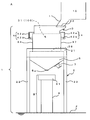
- the granulated powder cooling device 1 is composed of a support 2, a box 3, a cooling means 4, and a chute 5 as shown in FIG. (Including control panel).
- the support 2 supports the box 3 and the chute 5 and includes a rectangular support frame 21 and a plurality of support columns 22.
- the plurality of support columns 22 are arranged in a standing state on the floor F and support the support frame 21.
- the said box 3 accommodates the granulated powder 100 in the inside 31 temporarily.
- the box 3 has a square shape and is mounted on the support frame 21. Incidentally, the lower part of the box 3 is normally fixed to the support frame 21.
- the said cooling means 4 is forcedly cooled in the state which left the granulated powder 100 still.
- the stored powder leveling means 6 is provided on the upper part of the box 3 of the granulated powder cooling apparatus 1 according to the present invention.
- This accommodated powder leveling means 6 smoothes the granulated powder 100 accommodated in the interior 31 of the box 3 and makes the accumulated state of the granulated powder 100 uniform.
- the accommodated powder leveling means 6 of the present invention is not limited to the form shown in FIGS. 3 and 4.
- the discharge duct 11 of the mixer 10 is moved back and forth and / or left and right, or granulated.
- the rake for leveling the powder 100 is moved back and forth and / or left and right, the granulated powder can be secured in a uniform deposition state.
- the cooling means 4 in the granulated powder cooling device 1 according to the present invention forcibly cools the accommodated granulated powder 100 in a state where the granulated powder 100 is allowed to stand by the cooling body 41 disposed in the interior 31 of the box 3. Is. Therefore, according to the cooling means 4 of the present invention, it is possible to widen the cooling range of the granulated powder 100 in the box 3 without stirring the granulated powder 100, and the granulated particles are crushed. There is no fear of being done.
- the granulated powder cooling device 1 of the present invention uses such a chiller unit for the cooling means 4, compared with the conventional case where the box 3 itself is a cooling body, it has a simple configuration, The cooling range of the granulated powder 100 can be widened. Therefore, according to the granulated powder cooling apparatus 1 which concerns on this invention, the cooling time of the granulated powder 100 can be shortened rather than before, suppressing manufacturing cost.
- the cooling body cooling device 42 when the above-described configuration is adopted in the cooling means 4 of the present invention, the cooling body cooling device 42, the front water supply pipe 42b, the front branch water supply pipe 42a, and the cooling medium passage 41d of each cooling body 41 are provided.
- the cooling water can be circulated in the order of the rear branch water supply pipes 42 a, the rear water supply pipe 42 b, and the cooling body cooling device 42.
- water is used as the cooling medium used for the cooling means 4 of the present invention, but the present invention is not limited to this, and for example, nitrogen or the like can be used as appropriate.
- the cooling body 41 has an outer peripheral shape of a cross section perpendicular to the flow direction of the cooling medium having a polygonal shape such as a triangular shape or a quadrangular shape. preferable.
- the cooling body 41 of the present invention has a polygonal outer peripheral shape in a cross section perpendicular to the flow direction of the cooling medium (see FIGS. 5A to 5D).
- the cooling range of the granulated powder 100 can be widened without increasing the area occupied by the cooling body in the box 3 as compared with a cooling body having a circular outer peripheral shape in a cross section perpendicular to the flow direction.
- the cooling body 41 of this invention is a structure which consists of one, it arrange
- FIG. 6B when the cooling body 41 is arranged in a meandering manner and the folded portion is included in the box 3, the structure deposited in the vicinity of the folded portion. It is necessary to provide a gap between the folded portion and the box 3 to such an extent that the operation of dropping the particle powder 100 is possible.
- the cooling body 41 of this invention when arrange
- the cooling body 41 when the cooling body 41 is arranged in a state of standing in the box 3 in a substantially plate shape, at least one of the front surface or the back surface of the cooling body 41 is downward from above.
- the granulated powder 100 can easily slide on the front surface and / or the back surface of the cooling body 41. Therefore, by setting the cooling body 41 of the present invention to such a shape, accumulation of the granulated powder 100 on the cooling body 41 is suppressed, and the granulated powder 100 can be efficiently sent to the chute 5.
- vertical to the flow direction of the cooling medium of the said cooling body 41 is a mountain shape.
- the granulated powder cooling device 1 according to the present invention supplies the granulated powder 100 by forming at least the upper shape of the outer peripheral shape of the cross section perpendicular to the flow direction of the cooling medium of the cooling body 41 into a mountain shape. Occasionally, the granulated powder 100 falls while sliding on the upper slope of the cooling body 41, so that the bridging phenomenon hardly occurs in the box 3, and the granulated powder 100 can be efficiently accommodated in the box 3.
- FIG. 5A shows a form in which the upper portion 41a is formed in a mountain shape in the outer peripheral shape of the cross section perpendicular to the flow direction of the cooling medium of the cooling body 41 arranged in a standing state in the box 3. It is shown.
- FIG. 5 (a) when the cooling body 41 of the present invention has a substantially plate shape and is arranged in a standing state in the box 3, the surface 411 of the cooling body 41 is continuous vertically.
- the rear surface 412 of the cooling body 41 is also composed of two similar inclined surfaces 412a and 412b that are continuous in the vertical direction. It can be formed into a shape.
- the upper portion 41a in the outer peripheral shape of the cross section perpendicular to the flow direction of the cooling medium is not limited to the shape shown in FIG. 5A.
- FIG. The shape shown in FIG. 5 (g) can be obtained.
- FIGS. 5B and 5C in the outer peripheral shape of the cross section perpendicular to the flow direction of the cooling medium of the cooling body 41, only one side of the upper portion 41a is inclined (straight) from the upper side to the lower side. It is shown. 5 (e), FIG. 5 (f), and FIG. 5 (g), in the outer peripheral shape of the cross section perpendicular to the flow direction of the cooling medium of the cooling body 41, at least one side of the upper portion 41a is from top to bottom. An inclined (curved) form is shown.
- the cooling body 41 of the present invention it is more preferable that at least the lower shape of the outer peripheral shape of the cross section perpendicular to the flow direction of the cooling medium is an inverted mountain shape.
- the granulated powder cooling apparatus 1 according to the present invention has at least a lower part (a middle part 41b to a lower part 41c of the cooling body 41 in FIG. 5A) in the outer peripheral shape of the cross section perpendicular to the flow direction of the cooling medium of the cooling body 41.
- the granulated powder cooling device 1 employs the cooling body 41 having such a shape, so that when the granulated powder 100 is discharged, the contact between the granulated powder 100 and the cooling body 41 is reduced.
- the work efficiency accompanying the cooling treatment of the particle powder 100 can be further increased.
- the lower part (the part from the intermediate part 41b to the lower part 41c of the cooling body 41 in FIG. 5A) in the outer peripheral shape of the cross section perpendicular to the flow direction of the cooling medium is shown in FIG.
- the shape is not limited to the shape shown in FIG. 5A, and for example, the shape shown in FIGS. 5B to 5G can be used. 5 (b) to 5 (d) and FIG. 5 (f), in the outer peripheral shape of the cross section perpendicular to the flow direction of the cooling medium of the cooling body 41, the cooling in the lower part (FIG. 5 (a)).
- the outer peripheral shape of the cross section perpendicular to the flow direction of the cooling medium is not a polygonal shape, but has a substantially plate shape and the box 3
- the outer peripheral shape is arranged in an upright state and the lower portion of the outer peripheral shape is an inverted mountain shape, an effect substantially equivalent to the case where the outer peripheral shape is a polygonal shape can be exhibited.
- a plurality of cooling bodies 41 are provided in the box 3 and arranged at equal intervals along the left-right direction or the front-rear direction of the box 3. preferable.
- a plurality of cooling bodies 41 are provided in the box 3, so that the cooling medium 41 is provided in the box 3 of the cooling medium as compared with the case where a single cooling body 41 is provided in the box 3.
- the temperature difference between the vicinity of the inlet and the vicinity of the outlet can be reduced. Therefore, in the granulated powder cooling apparatus 1 according to the present invention, by providing a plurality of cooling bodies 41 in the box 3, the variation in the cooling rate of the granulated powder 100 in the box 3 is suppressed, and the box All the granulated powder 100 in 3 can be efficiently cooled. Therefore, the granulated powder cooling device 1 according to the present invention can reduce the cooling time and quality of the granulated powder 100 as the number of the cooling bodies 41 provided in the box 3 increases.
- the granulated powder cooling device 1 preferably further includes vibration devices 7 and 8 for vibrating the chute 5 and / or the box 3.
- the quality of the granulated particles constituting the granulated powder 100 is changed by hitting the box 3 before discharging the granulated powder 100 after cooling. It is more preferable to further include a vibration device 8 that crushes the granulated powder cake that has been pseudo-solidified by cooling without causing it to cool.
- the granulated powder cooling device 1 according to the present invention can further be provided with a vibration device 8 at an intermediate portion of the front wall 34 of the box 3 as shown in FIG.
- the vibration device 8 preferably employs a hammering method or the like and strikes the box 3 a predetermined number of times.
- the granulated powder cooling device 1 according to the present invention can pulverize the granulated powder cake by using the vibration device 8 without changing the quality of the granulated particles.
- the granulated powder cooling device 1 according to the present invention can collect the granulated powder 100 that has been cooled in a state before cooling, and suppress the quality degradation of the cooled granulated powder 100. I can do it.
- the granulated powder cake is a product in which the granulated powder 100 is pseudo-solidified by cooling.
- the vibration device 8 is preferably an air knocker or the like that performs an impacting operation such that when the granulated powder cake is crushed, the piston in the inside vigorously pops out and strikes the object. Can be used.
- the granulating apparatus A according to the present invention is a mixer for producing the granulated powder 100 by mixing the granulated powder cooling apparatus 1 of the present invention and two or more kinds of raw material powders while heating. It is equipped with.
- the granulating apparatus A is centrally managed by control means (including a control panel) (not shown) to control the discharge of the granulated powder 100 from the discharge duct 11, the front door 38a of the box 3, and It is possible to perform various controls such as opening / closing control of the rear door 38b, operation control of the cooling means 4, control of the stored powder leveling means 6, operation control of the vibration devices 7 and 8.
- the discharge duct 11 moves and supplies the formed granulated powder 100 to the inside 31 of the box 3.
- the bottom 38 of the box 3 is in a closed state. That is, the granulated powder 100 in a heated state is temporarily stored in the interior 31 of the box 3.
- the accommodated powder leveling means 6 is operated.
- the flattening rod 62 rotates horizontally within a range in the direction of arrow R in FIG. 4 for a predetermined time in a manner similar to that of the automobile wiper.
- the flattening rod 62 the granulated powder 100 is deposited in a uniform thickness.
- the cooling means 4 operates from the stage of storing the granulated powder 100 in the box 3.
- the cooling means 4 is configured such that the cooling water supplied from the cooling body cooling device 42 is supplied with a plurality of branch water supply pipes 42a and a plurality of cooling bodies via a water supply pipe 42b (only one water supply pipe is shown in FIG. 4). 41, it is made to circulate with the cooling body cooling device 42 through the water supply pipe 42b (the water supply pipe which illustration was omitted in FIG. 4).
- Each cooling body 41 is cooled by the circulation of the cooling water, and the granulated powder 100 in contact with the cooling body 41 is cooled.
- the granulated powder 100 is forcibly cooled in a state where the granulated powder in a heated state is allowed to stand, and this is a major feature of the granulated cooling apparatus 1 according to the present invention.
- the front door 38a and the rear door 38b of the bottom portion 38 of the box 3 are opened, and the granulated powder cake that has been solidified in a pseudo and gentle manner by cooling is obtained. Crush and drop without changing.
- the vibration device (knocker) 8 is operated to strike the side wall surface of the box 3 a predetermined number of times. Thereby, the said granulated powder cake is crushed and the fall of the granulated powder 100 adhering to the inner wall of the box 3 and the cooling body 41 is promoted.
- the granulated powder discharged from the bottom 38 of the box 3 passes through the chute 5 and falls onto the shifter (sieving) 91 of the shifter means B.
- a vibration device (vibrator) 7 is provided on the inner wall surface of the chute 5, and the granulated powder adhering to the inner wall surface of the chute 5 is efficiently dropped by applying vibration to the chute 5. Improve 100 collection efficiency.
- the shifter means B in which the shifter (sieving) 91 and the base 9 are integrated uses the shifter (sieving) 91 to swing it and drop the granulated powder 100.
- the granulated powder 100 that has been subjected to the sizing treatment falling from the shifter (sieving) 91 falls into the hopper 51 mounted on the moving carriage 50 and is stored as shown in FIG.
- the granulation apparatus A repeats the series of processes described above a predetermined number of times.
- the hopper 51 is transported to the molding machine together with the movable carriage 50, and the granulated powder 100 in the hopper 51 is used for mold molding.
- the granulating apparatus A enables the granulated powder cooling apparatus 1 to forcibly cool the granulated powder 100 in a heated state. That is, since the granulated powder cooling device 1 is cooling without moving the particles of the granulated powder 100, the granulated particles are destroyed, sheared, and generated in the cooling process of the conventional screw feeder type cooling device. Particle detachment is suppressed. Therefore, by using the granulating apparatus A according to the present invention, even if a cooling process is performed after heating and granulating, the mold fluidity provided by the granulated particles immediately after granulation is not greatly deteriorated, and the mold molding is performed. A granulated powder 100 having powder fluidity suitable for the above can be obtained.
- the granulated powder 100 was manufactured using the mixer 10, and this granulated powder 100 was cooled using the granulated powder cooling apparatus 1 according to the present invention.
- each powder of iron powder, hard powder (alloy powder), and lubricant was used as the raw material powder of the granulated powder 100 used in this example.
- the sampling amount which assumed the feeder cup was taken out from fixed quantity of the granulated powder 100 which cooling was complete
- This tester is capable of collecting a certain amount of granulated powder 100 and swinging it when the granulated powder with an appropriate particle size falls and measures the collected amount (g) It is.
- the amount of granulated powder with an appropriate particle size when the tester was swung 20 times was measured.
- the average value of the amount collected per oscillation was determined from the total amount of the collected granulated powder. This average value was 31.46 g.
- the granulated powder 100 obtained in the same manner as in the example was cooled using a screw feeder type granulated powder cooling device. And the collection amount of the granulated powder 100 was measured by the same method as an Example using the same testing machine as an Example. And the average value of the amount collected was calculated in the same manner as in the example. This average value was 28.42 g.
- the granulated powder cooling device according to the present invention described above and the granulating device including the granulated powder are cooled in a stationary state without moving the granulated particles in the cooling process of the granulated powder.
- the granulated particles can be cooled without changing the particle diameter that exhibits good powder flowability. Therefore, the granulated powder cooling apparatus and the granulating apparatus equipped with the granulated powder cooling apparatus according to the present invention are prepared by mixing two or more kinds of raw material powders and granulating them, and then adjusting the granulated particles in the powder metallurgy field using die molding. It can be suitably used for granulated particle adjustment of a raw material for producing a low-temperature fired ceramic material, granulated particle adjustment in the cemented carbide field and the like.
- a granulator B shifter means 1 granulated powder cooling device 3 box 4 cooling means 5 chute 5a discharge port 6 contained powder leveling means 7 vibration device 8 vibration device 10 mixer 11 discharge port 31 inside 32 supply port 38 bottom 41 Cooling body 41a Upper part 41c Lower part 41d Cooling medium passage 42 Cooling body cooling device 42a Branch water feeding pipe 42b Water feeding pipe 100 Granulated powder 411 Surface 411a Slope 411b Slope 412 Back face 412a Slope 412b Slope
Abstract
粉末流動性を低下させずに造粒粉を冷却出来る造粒粉冷却装置及びこれを備えた造粒装置の提供を目的とする。この目的を達成するため、箱体と、冷却手段と、当該箱体の底部に設けられたシュートとを備え、当該箱体は、上部に当該造粒粉の供給口を有し、且つ、底部が開閉可能であって、当該造粒粉が当該供給口から供給される際には当該底部を閉じて当該造粒粉を内部に一時的に収容し、当該冷却手段は、当該箱体内に一時的に収容された当該造粒粉を静置させた状態で強制的に冷却し、当該シュートは、当該造粒粉の冷却終了後に当該箱体の底部が開けられることにより、冷却が終了した当該造粒粉を排出することを特徴とする造粒粉冷却装置を採用する。
Description
本件発明は、二種類以上の原料粉を加熱しながら混合して得られた造粒粉を冷却して採取する際に用いられる造粒粉冷却装置及びこれを備えた造粒装置に関する。
従来より、二種以上の粉体(硬質粒子を含む)から成る耐摩耗性を有する焼結体には、例えば、粉末成形機の成形用金型に鉄粉を主とする混合粉を入れて圧縮成形し、焼結したものが用いられている。ちなみに、二種以上の粉体から成る、耐摩耗性を有する焼結体を作製するために、鉄粉と硬質粉(硬質粒子等で構成した粉体)に潤滑剤を加え、加熱しながらミキサーを用いて混合することにより、鉄粒子と潤滑剤と硬質粒子とが結合した造粒粒子を得ることが出来る。このようにして得られた造粒粒子を用いることで、混合粉の原料となる粒子同士に凝集が生じたり、混合粉中において原料となる粒子の偏在が生じるのを抑制して、所望の特性を備えた燒結体を得ることが出来る。但し、上述した方法によって得られた造粒粒子からなる造粒粉は、高温となるため、一旦冷却しなければ流動性が低く、均一な成形体が得られない。
なお、この造粒粉を冷却する装置としては、スクリューフィーダ式の冷却装置の使用が提案されている(特許文献1参照)。このスクリューフィーダ式の冷却装置による造粒粉の冷却方法は、まず、造粒粉が上部の供給口からケーシング内に供給される。そして、ケーシング内に供給された造粒粉は、当該ケーシング内に設けられたスクリューが回転することにより、当該造粒粉を下部の排出口へ移送する。ここで、スクリューシャフト内には冷却媒体が供給されており、スクリューが冷却されているため、造粒粉は、このスクリューによって冷却されながら下部の排出口へ移送される。
しかしながら、特許文献1のスクリューフィーダ式の造粒粉冷却装置は、造粒粉をスクリューで撹拌しながら冷却するために、良好な粒径を備えた造粒粒子が解砕する場合があり、好ましくない。このような場合には、鉄粒子から硬質粒子が脱離したり、造粒粒子全体が細かく破砕されることにより、造粒粒子の品質が変化することとなる。例えば、特許文献1のスクリューフィーダ式の造粒粉冷却装置を用いた場合、冷却前の造粒粒子が良好な粒径を備えていたとしても、冷却後には当該造粒粒子の粒子径が細かくなり、粉末流動性の低下を招いてしまう。
このような現象が起こると、冷却が終了した造粒粉を成形用金型へ供給しても、造粒粉の粉末流動性が低下しているため、金型に十分な量の造粒粉を供給出来ない場合がある。更に、このような場合、金型に供給された粉体を押圧成形しようとしても、圧力成形機の種類によっては、十分な押圧をかけることが出来なかったり、又は、押圧をかけ過ぎてしまったりすることとなり、良好な金型成形歩留まりを得られなくなる。
以上、本件発明は、上述の課題を解決するためになされたものであって、その目的は、粉末流動性を低下させずに造粒粉を冷却出来る造粒粉冷却装置及びこれを備えた造粒装置を提供することである。
そこで、本件発明者等は、鋭意研究を行った結果、上述した課題を解決するために、以下に示す造粒粉冷却装置及び造粒装置を採用した。
本件発明に係る造粒粉冷却装置: 本件発明の造粒粉冷却装置は、二種類以上の原料粉を加熱しながら混合して得られた造粒粉を冷却して採取する際に用いられる造粒粉冷却装置であって、当該造粒粉冷却装置は、箱体と、冷却手段と、当該箱体の底部に設けられたシュートとを備え、当該箱体は、上部に当該造粒粉の供給口を有し、且つ、底部が開閉可能であって、当該造粒粉が当該供給口から供給される際には当該底部を閉じて当該造粒粉を内部に一時的に収容し、当該冷却手段は、当該箱体内に一時的に収容された当該造粒粉を静置させた状態で強制的に冷却し、当該シュートは、当該造粒粉の冷却終了後に当該箱体の底部が開けられることにより、冷却が終了した当該造粒粉を排出することを特徴としている。
また、本件発明に係る造粒粉冷却装置において、前記冷却手段は、前記箱体内に配置された冷却体と、当該冷却体に接続して当該冷却体を冷却する冷却体冷却装置とを備え、当該冷却体は、当該冷却体冷却装置を利用して前記造粒粉を静置させた状態で強制的に冷却することが好ましい。
また、本件発明に係る造粒粉冷却装置において、前記冷却体は、内部に冷却媒体用通路を有し、前記冷却体冷却装置は、当該冷却媒体用通路の両端に接続して、当該冷却体との間で冷却媒体を循環させることが好ましい。
また、本件発明の造粒粉冷却装置において、前記冷却体は、冷却媒体の流れ方向に垂直な断面の外周形状が、三角形状、四角形状等の多角形状を呈したものであることが好ましい。
また、本件発明に係る造粒粉冷却装置において、前記冷却体は、前記箱体内において、当該箱体の左右方向又は前後方向に沿って複数列に起立した状態で配置したことが好ましい。
また、本件発明に係る造粒粉冷却装置において、前記冷却体は、前記箱体内に複数設けられ、当該箱体の左右方向又は前後方向に沿って等間隔をあけて配置したことが好ましい。
また、本件発明に係る造粒粉冷却装置は、前記シュート及び/又は前記箱体を振動させるための振動装置を更に備えたことが好ましい。
本件発明に係る造粒装置: 本件発明に係る造粒装置は、本件発明に係る造粒粉冷却装置と、二種類以上の原料粉を加熱しながら混合して造粒粉を製造するミキサーとを備えたことを特徴としている。
本件発明に係る造粒粉冷却装置は、加熱によって得られた造粒粉を静置した状態で強制冷却することが可能であるため、造粒粒子の解砕を抑止することが出来る。従って、本件発明の造粒粉冷却装置によれば、粉末流動性を低下させずに造粒粉を冷却することが出来る。以上のことから、本件発明に係る造粒粉冷却装置によれば、冷却された造粒粉を用いて粉末成形を行う場合に、金型に十分な量の造粒粉を供給することが可能となるため、金型成形工程において金型への供給粉体量のバラツキが減少し、良好な金型成形歩留まりが得られるようになる。
また、本件発明に係る造粒装置においても、本件発明の造粒粉冷却装置を用いたことで、加熱によって得られた造粒粉を冷却する際に造粒粒子の解砕を抑え、粉末流動性を低下させずに造粒粉を冷却することが出来る。また、本件発明に係る造粉装置によれば、本件発明の造粒粉冷却装置が有する、製造コストの低減や造粒粉の冷却時間の短縮等に関する効果も併せて得ることが出来る。
以下、本件発明の実施の形態について、図を用いて具体的に説明していく。
本件発明に係る造粒粉冷却装置: 本件発明に係る造粒粉冷却装置1は、二種類以上の原料粉を加熱しながら混合して得られた造粒粉100を冷却して採取する際に用いられる造粒粉冷却装置である。そして、当該造粒粉冷却装置1は、箱体3と、冷却手段4と、当該箱体3の底部38に設けられたシュート5とを備えたものである。ここで、当該箱体3は、上部に当該造粒粉100の供給口32を有し、且つ、底部38が開閉可能であって、当該造粒粉100が当該供給口32から供給される際には当該底部38を閉じて当該造粒粉100を内部に一時的に収容する。また、当該冷却手段4は、当該箱体3内に一時的に収容された当該造粒粉100を静置させた状態で強制的に冷却する。また、当該シュート5は、当該造粒粉100の冷却終了後に当該箱体3の底部38が開けられることにより、冷却が終了した当該造粒粉100を排出する。
図1に示すように、本件発明に係る造粒粉冷却装置1は、ミキサー10によって形成された造粒粉100を冷却するものである。ちなみに、ミキサー10は、二種類以上の原料粉を加熱しながら混合して造粒粉100を形成するものである。この造粒粉100は、多数の造粒粒子から構成されたものであり、各造粒粒子は、異なる原料粉の粒子が結合したものである。このミキサー10は、その上部に、図示せぬ原料粉の投入口が設けられている。そして、ミキサー10の駆動時には、当該投入口からミキサー10の内部に原料粉が供給され、ミキサー10の内部で供給された原料粉を加熱しながら混合するように構成されている。このミキサー内での混合方法に関しては特段の限定はない。そして、ミキサー10本体の下部には当該ミキサー10の内部で形成された造粒粉100の排出ダクト11が設けられる。
また、本件発明に係る造粒粉冷却装置1は、図1に示す、支持体2と、箱体3と、冷却手段4と、シュート5とを中心とした構成からなり、図示せぬ制御装置(コントロールパネルを含む)により制御される。なお、当該支持体2は、箱体3及びシュート5を支持するものであり、角形の支持枠21と、複数の支柱22とから構成されている。そして、複数の支柱22は、フロアFに起立した状態で配置され支持枠21を支える。そして、当該箱体3は、その内部31に造粒粉100を一時的に収容するものである。この箱体3は、角形状であって、支持枠21に搭載配置される。ちなみに、通常は、箱体3の下側部分が支持枠21に固定される。そして、当該冷却手段4は、造粒粉100を静置した状態で強制的に冷却するものである。そして、当該シュート5は、冷却が終了した造粒粉100を排出口5aより排出するものであり、箱体3の底部38に設けられる。例えば、このシュート5は、断面略三角形の筒状に形成され、図1に示すように、底部38の二つの扉38a、38bが閉状態又は開状態でも、この二つの扉38a、38bを常に覆うように形成される。
図1に示すように、箱体3の上部の後方側には、造粒粉100の供給口32が設けられている。これを具体的に説明すると、図3及び図4(b)に示すように、箱体3は天板33を備えている。そして、図4(b)から分かるように、この天板33は、箱体3の前壁34と、左右側壁の35、36の前側部分に結合されている。これにより、天板33と後壁37との間には空間が形成されており、この空間が前記供給口32を構成している。なお、図1に示すように、この供給口32には、ミキサー10の排出ダクト11が接続されている。
また、図1に示すように、箱体3の底部38は、開閉可能に構成されている。具体的に説明すると、当該底部38は、前扉38a及び後扉38bを備えている(鎖線で図示)。そして、この前扉38aは、その一端部が箱体3の前壁34の下端部に軸支される。また、後扉38bも、その一端部が箱体3の後壁37の下端部に軸支される。すなわち、当該底部38は、開閉自在に構成されるこれら前扉38a及び後扉38bにより、当該造粒粉100を内部に一時的に収容して冷却し、また、冷却が終了した当該造粒粉100を排出することが出来る。
なお、図1には示されていないが、本件発明に係る造粒粉冷却装置1は、図2に示すように、シュート5の下方に、シフター手段Bを配置することも出来る。このシフター手段Bは、シフター(篩)91と台9とが一体化したものであり、台9の上部にシフター(篩)91を配置したものである。本件発明に係る造粒粉冷却装置1は、シフター(篩)91を構成に含めることで、生産効率と造粒粒子の品質との向上を図ることが可能となる。また、当該台9に関しては、その高さを適正な位置に調整することで、粒粉100の当該シフター(篩)91への供給を問題なく行うことが出来るようになる。そして、本件発明に係る造粒粉冷却装置1は、図3に示すように、シフター(篩)91の上方に、羽根車を回転駆動させて造粒粉100の当該シフター(篩)91への供給量を一定に保つためのロータリーフィーダ70を配設することも出来る。
また、本件発明に係る造粒粉冷却装置1は、箱体3内に一時的に収容された造粒粉100を冷却する前に、当該造粒粉100を均一な厚さで堆積した状態にする収容粉体水平化手段6を更に備えることも出来る。
図3に示すように、本件発明に係る造粒粉冷却装置1の箱体3の上部には、収容粉体水平化手段6が設けられている。この収容粉体水平化手段6は、箱体3の内部31に収容された造粒粉100をならして、造粒粉100の堆積状態を一様にするものである。
本件発明の収容粉体水平化手段6は、図3及び図4に例示するように、回転軸61と、平坦化ロッド62とを備えたものとすることが出来る。図3において、当該平坦化ロッド62は、その一端部が箱体3の内部31に位置する回転軸61の下端部に連結された構成が示されている。また、図4(a)及び図4(b)には、本件発明における収容粉体水平化手段6を構成する回転軸61が、箱体3の中央部分で天板33を貫通して設けられているのが示されている。そして、図4(a)において、当該平坦化ロッド62は、回転軸61が正逆方向に回転することにより、矢印Rで示される範囲を水平に回動する構成が示されている。なお、本件発明の収容粉体水平化手段6は、図3及び図4に示す形態に限定されるものではなく、例えばミキサー10の排出ダクト11を前後及び/又は左右に移動させたり、造粒粉100を平らにならすためのレーキを前後及び/又は左右に移動させる形態を採用して、造粒粉を一様な堆積状態に確保することが出来る。
また、本件発明に係る造粒粉冷却装置1において、冷却手段4は、箱体3内に配置された冷却体41と、当該冷却体41に接続して当該冷却体41を冷却する冷却体冷却装置42とを備え、当該冷却体41は、当該冷却体冷却装置42を利用して造粒粉100を静置させた状態で強制的に冷却することが好ましい。
本件発明に係る造粒粉冷却装置1における冷却手段4は、箱体3の内部31に配置された冷却体41によって、収容された造粒粉100を静置させた状態で強制的に冷却するものである。従って、本件発明の冷却手段4によれば、造粒粉100を撹拌しなくとも、箱体3内における造粒粉100の冷却範囲を広くすることが可能となり、また、造粒粒子が解砕される恐れが生じない。
また、本件発明に係る造粒粉冷却装置1において、冷却体41は、内部に冷却媒体用通路41dを有し、冷却体冷却装置42は、当該冷却媒体用通路の両端に接続して、当該冷却体41との間で冷却媒体を循環させることが好ましい。
本件発明に係る造粒粉冷却装置1の冷却手段4は、冷却媒体に水を用いることが出来、例えばこの場合、図3及び図4に示すように、冷却水を、冷却体冷却装置42から、送水管42b(図4では、一本の送水管のみを図示)を介して、複数の分岐送水管42a、複数の冷却体41、送水管42b(図4で図示を省略した送水管)を経て、冷却体冷却装置42へと循環させるチラーユニットを採用することが出来る。本件発明の造粒粉冷却装置1は、冷却手段4にこのようなチラーユニットを用いることで、従来のような箱体3自体を冷却体にする場合に比べ、簡単な構成でありながらも、造粒粉100の冷却範囲を広くすることが可能になる。よって、本件発明に係る造粒粉冷却装置1によれば、製造コストを抑制しつつ、従来よりも造粒粉100の冷却時間を短縮することが出来る。
図3、図4には、2本の送水管42bと多数の分岐送水管42aを設けた造粒粉冷却装置1が示されている。本件発明に係る造粒粉冷却装置1は、図3、図4に示す構成に限定されるものではなく、図6に示すように、送水管42bを単数用いる構成としてもよい。本件発明に係る造粒粉冷却装置1は、送水管42bを単数用いる構成を採用しても、図6に示すように、造粒粉100と冷却体41との接触面積を増大させて冷却範囲を広くすることで、大きな冷却効果を得ることが出来る。
なお、本件発明の冷却手段4を構成する分岐送水管42aは、箱体3の前壁34及び後壁37に貫通して設けることが出来る。ちなみに図4には、前壁34側の複数の分岐送水管42aが、箱体3の左右方向に等間隔に並んで配置されているのが示されている。本件発明の冷却手段4を構成する分岐送水管42aは、各冷却体41の冷却媒体用通路41d(図5参照のこと。)の一端と他端とに接続され、後壁37側の複数の分岐送水管42aが、前壁34側の複数の分岐送水管42aと対向するように、箱体3の左右方向に等間隔に並べて配置することが出来る。
すなわち、本件発明の冷却手段4において、上述の構成を採用した場合には、冷却体冷却装置42、前側の送水管42b、前側の各分岐送水管42a、各冷却体41の冷却媒体用通路41d、後側の各分岐送水管42a、後側の送水管42b、冷却体冷却装置42の順に、冷却水を循環させることが出来る。また、以上の説明では本件発明の冷却手段4に用いる冷却媒体として水を用いているが、本件発明はこれに限定されず、例えば窒素等を適宜用いることが出来る。
また、本件発明に係る造粒粉冷却装置1において、冷却体41は、冷却媒体の流れ方向に垂直な断面の外周形状が、三角形状、四角形状等の多角形状を呈したものであることが好ましい。
本件発明の冷却体41は、冷却媒体の流れ方向に垂直な断面の外周形状が多角形状であることで(図5(a)~図5(d)参照のこと。)、例えば、冷却媒体の流れ方向に垂直な断面の外周形状が円形の冷却体と比べて、箱体3内における冷却体占有面積を増大させずに、造粒粉100の冷却範囲を広くすることが可能になる。
また、本件発明に係る造粒粉冷却装置1において、冷却体41は、箱体3内において、当該箱体3の左右方向又は前後方向に沿って複数列に起立した状態で配置したことが好ましい。
図3において、複数の冷却体41は、箱体3の内部31に設けられた収容粉体水平化手段として用いる平坦化ロッド62よりも下側の位置に起立した状態で配置しているのが示されている。これを具体的に説明すると、図3に示す複数の冷却体41は、起立した状態で、箱体3の左右方向に並んで配置されている。そして、図4において、各冷却体41の両側の端部が、箱体3の前壁34及び後壁37に結合されているのが示されている。本件発明に係る造粒粉冷却装置1は、このような構成を採用することで、複数の冷却体41が箱体3内に横設された場合に比べて、造粒粉100の供給時に、冷却体41に造粒粉100が堆積するのを防ぐことが出来る。このため、作業者が、造粒粉冷却装置1を一旦止めて、冷却体41に堆積した造粒粉100を落とす作業が不要になり、造粒粉100の冷却処理に伴う作業効率を高めることが出来る。
また、本件発明に係る造粒粉冷却装置1は、冷却体41を箱体3の左右方向又は前後方向に複数列に起立した状態で配置することで、冷却体41を箱体3内で斜め方向に並べて配置した場合や、箱体3内に複数列に起立した状態で配置されていない場合に比べて、造粒粉100を均一に冷却することが可能になる。また、当該冷却体41を、箱体3内に起立した状態で配置することで、冷却体41上への造粒粉100の堆積が少なくなり、作業効率を高めることが出来る。
なお、本件発明の冷却体41は、単数からなる構成であっても、造粒粉100と冷却体41との接触面積が大きくなるように、箱体3内に蛇行状に配置して複数列を形成することで(図6(a),(b)参照のこと。)、冷却効率を増大させることが出来る。なお、図6(b)に示すように、冷却体41を蛇行状に配置した場合であって、折り返し部分を箱体3内に含める構成とする場合には、当該折り返し部分付近に堆積した造粒粉100を落とす作業が可能な程度に、当該折り返し部分と箱体3との間に隙間を設ける必要がある。
また、本件発明の冷却体41は、箱体3内に起立した状態で配置される場合において、略プレート形状を呈し、その表面又は裏面の少なくとも一方が、上方から下方へ傾斜する面を有することがより好ましい。本件発明に係る造粒粉冷却装置1は、冷却体41を略プレート状として箱体3内に起立した状態で配置したときに、当該冷却体41の表面又は裏面の少なくとも一方が上方から下方へ傾斜する斜面を有することで、造粒粉100が冷却体41の表面及び/又は裏面を滑りやすくなる。従って、本件発明の冷却体41は、かかる形状とすることで、冷却体41上への造粒粉100の堆積が抑止され、造粒粉100をシュート5へ効率良く送ることが出来る。
ここで、本件発明の冷却体41は、当該冷却体41の冷却媒体の流れ方向に垂直な断面の外周形状における少なくとも上部の形状が、山形状であることがより好ましい。本件発明に係る造粒粉冷却装置1は、冷却体41の冷却媒体の流れ方向に垂直な断面の外周形状における少なくとも上部の形状が山形状に形成されていることで、造粒粉100の供給時に、造粒粉100が冷却体41の上側の斜面を滑りながら落ちていくため、箱体3内でブリッジ現象の発生が起こり難く、造粒粉100を箱体3内に効率良く収容出来る。
図5(a)には、箱体3内に起立した状態で配置した冷却体41の、冷却媒体の流れ方向に垂直な断面の外周形状において、その上部41aが山形状に形成された形態が示されている。図5(a)に示すように、本件発明の冷却体41は、略プレート形状を呈し且つ箱体3内に起立した状態で配置された場合に、当該冷却体41の表面411が上下に連続した二つの斜面411a、411bから構成され、当該冷却体41の裏面412も、上下に連続した同様の二つの斜面412a、412bから構成され、上部41aが、当該斜面411aと当該斜面412aとにより山形状に形成されたものとすることが出来る。
なお、本件発明の冷却体41は、その冷却媒体の流れ方向に垂直な断面の外周形状における上部41aが、図5(a)に示す形状に限定されるものでなく、例えば図5(b)~図5(g)に示す形状とすることが出来る。ここで、図5(b)、図5(c)には、冷却体41の冷却媒体の流れ方向に垂直な断面の外周形状において、上部41aの片側のみ上方から下方へ傾斜(直線)した形態が示されている。また、図5(e)、図5(f)、図5(g)には、冷却体41の冷却媒体の流れ方向に垂直な断面の外周形状において、上部41aの少なくとも片側が上方から下方へ傾斜(曲線)した形態が示されている。
ここで、図5(e)~図5(g)に示す冷却体41に関しては、冷却媒体の流れ方向に垂直な断面の外周形状が多角形状ではないが、略プレート形状を呈し且つ箱体3内で起立した状態で配置された場合に、当該外周形状の上部が山形状であれば、当該外周形状が多角形状のものを用いた場合とほぼ同等の効果を発揮することが出来る。
また、本件発明の冷却体41は、冷却媒体の流れ方向に垂直な断面の外周形状における少なくとも下部の形状が、逆山形状であることがより好ましい。本件発明に係る造粒粉冷却装置1は、冷却体41の冷却媒体の流れ方向に垂直な断面の外周形状における少なくとも下部(図5(a)における冷却体41の中間部41bから下部41cにかけての部分)の形状が逆山形状に形成されていることで、造粒粉100の排出時に、冷却体41の下側の斜面から造粒粉100の脱離が容易となり、造粒粉100をシュート5へ効率良く落下させることが出来る。本件発明に係る造粒粉冷却装置1は、このような形状の冷却体41を採用することで、造粒粉100の排出時に、造粒粉100と冷却体41との接触が少なくなり、造粒粉100の冷却処理に伴う作業効率を更に高めることが出来る。
図5(a)には、箱体3内に起立した状態で配置した冷却体41の、冷却媒体の流れ方向に垂直な断面の外周形状において、下部(図5(a)における冷却体41の中間部41bから下部41cにかけての部分)が逆山形状に形成された形態が示されている。図5(a)に示すように、本件発明の冷却体41は、略プレート形状を呈し且つ箱体3内に起立した状態で配置された場合に、当該冷却体41の表面411が上下に連続した二つの斜面411a、411bから構成され、当該冷却体41の裏面412も、上下に連続した同様の二つの斜面412a、412bから構成され、下部(図5(a)における冷却体41の中間部41bから下部41cにかけての部分)が、当該斜面411bと当該斜面412bとにより逆山形状に形成されたものとすることが出来る。
なお、本件発明の冷却体41は、その冷却媒体の流れ方向に垂直な断面の外周形状における下部(図5(a)における冷却体41の中間部41bから下部41cにかけての部分)が、図5(a)に示す形状に限定されるものでなく、例えば図5(b)~図5(g)に示す形状とすることが出来る。ここで、図5(b)~図5(d)、図5(f)には、冷却体41の冷却媒体の流れ方向に垂直な断面の外周形状において、下部(図5(a)における冷却体41の中間部41bから下部41cにかけての部分)の少なくとも片側が上方から下方へ傾斜(直線)した形態が示されている。また、図5(e)、図5(g)には、冷却体41の冷却媒体の流れ方向に垂直な断面の外周形状において、下部(図5(a)における冷却体41の中間部41bから下部41cにかけての部分)の少なくとも片側が上方から下方へ傾斜(曲線)した形態が示されている。そして、図5(c)、図5(d)、には、冷却体41の冷却媒体の流れ方向に垂直な断面の外周形状において、下部(図5(a)における冷却体41の中間部41bから下部41cにかけての部分)の少なくとも片側が、上方から下方へ傾斜(直線)した部分と非傾斜(直線)部分との組合せにより構成された形態が示されている。
ここで、図5(e)~図5(g)に示す冷却体41に関しては、冷却媒体の流れ方向に垂直な断面の外周形状が多角形状ではないが、略プレート形状を呈し且つ箱体3内で起立した状態で配置された場合に、当該外周形状の下部が逆山形状であれば、当該外周形状が多角形状のものを用いた場合とほぼ同等の効果を発揮することが出来る。
また、本件発明に係る造粒粉冷却装置1において、冷却体41は、箱体3内に複数設けられ、当該箱体3の左右方向又は前後方向に沿って等間隔をあけて配置したことが好ましい。
本件発明に係る造粒粉冷却装置1は、冷却体41を箱体3内に複数設けることで、冷却体41を箱体3内に単数設けた場合に比べて、冷却媒体の箱体3内における入口付近と出口付近との温度差を小さくすることが出来る。そのため、本件発明に係る造粒粉冷却装置1において、冷却体41を箱体3内に複数設けることで、箱体3内における造粒粉100の冷却速度の場所的バラツキを抑制し、箱体3内全ての造粒粉100を効率良く冷却することが可能になる。従って、本件発明に係る造粒粉冷却装置1は、箱体3内に設ける冷却体41の数が増える程、造粒粉100の冷却時間の短縮化及び高品質化を図ることが出来る。
また、本件発明に係る造粒粉冷却装置1は、箱体3内において、複数の冷却体41を当該箱体3の左右方向又は前後方向に等間隔に並べて起立した状態で配置することで、複数の冷却体41を箱体内で斜め方向に並べて配置した場合や、複数の冷却体41が箱体3内に等間隔をあけて配置されていない場合に比べて、造粒粉100を均一且つ迅速に冷却することが可能となる。なお、本件発明に係る造粒粉冷却装置1において、使用する冷却体41の枚数は、箱体3の造粒粉100収容量等に応じて適宜設定することが出来る。
また、本件発明に係る造粒粉冷却装置1は、シュート5及び/又は箱体3を振動させるための振動装置7,8を更に備えることが好ましい。
ここで、本件発明に係る造粒粉冷却装置1において、冷却が終了した造粒粉100を排出した後にシュート5を振動させて、当該シュート5に付着した当該造粒粉100を、当該造粒粉100を構成する造粒粒子の品質を変化させることなく落とす振動装置7を更に備えることがより好ましい。
本件発明に係る造粒粉冷却装置1は、図1及び図3に示すように、シュート5の側面に振動装置7を設けることが出来る。この振動装置7は、シュート5を振動させることで、シュート5に付着した造粒粉100を、造粒粒子の品質を変化させることなく落とすためのものである。本件発明の造粒粉冷却装置1は、シュート5の側面に振動装置7を設けることにより、シュート5に付着した造粒粉100を採取することが可能になり、冷却が終了した造粒粉100の回収率を高めることが出来る。なお、この振動装置7には、構造が簡単で且つ取扱いが安全なエアー式バイブレーターや、高周波振動を発生させるモーター式バイブレーター等を適宜用いることが出来る。
また、本件発明に係る造粒粉冷却装置1において、冷却が終了した造粒粉100を排出する前に箱体3を叩くことにより、当該造粒粉100を構成する造粒粒子の品質を変化させることなく、冷却によって擬似的に固化した造粒粉ケーキを解砕する振動装置8を更に備えることがより好ましい。
本件発明に係る造粒粉冷却装置1は、図1に示すように、箱体3の前壁34の中間部分に、更に振動装置8を設けることが出来る。この振動装置8は、ハンマリング方式等を採用して箱体3を所定の回数叩くものであることが好ましい。本件発明に係る造粒粉冷却装置1は、振動装置8を用いることで、造粒粒子の品質を変化させずに造粒粉ケーキを解砕することが出来る。本件発明に係る造粒粉冷却装置1は、かかる構成において、冷却が終了した造粒粉100を冷却前の状態で採取することが可能になり、冷却された造粒粉100の品質低下を抑えることが出来る。ここで、造粒粉ケーキとは、造粒粉100が冷却によって擬似的に固化したものである。なお、この振動装置8には、造粒粉ケーキを解砕するに際して、圧縮空気の力により中のピストンが勢いよく飛び出して対象物を叩くような加撃作動を行う、エアーノッカー等を好適に用いることが出来る。
本件発明に係る造粒装置: 本件発明に係る造粒装置Aは、本件発明の造粒粉冷却装置1と、二種類以上の原料粉を加熱しながら混合して造粒粉100を製造するミキサーとを備えたものである。
図1及び図2に示すように、本件発明に係る造粒装置Aは、排出ダクト11を備えるミキサー10(一点鎖線で図示)と、本件発明の造粒粉冷却装置1とを備え、二種類以上の原料粉を用いて造粒粉100を製造するものである。本件発明に係る造粒装置Aは、本件発明に係る造粒粉冷却装置1を備えることで、加熱によって得られた造粒粉100を冷却する際に造粒粒子が解砕されることなく、高品質の造粒粉100を得ることが出来る。なお、本件発明に係る造粒装置Aは、図示せぬ制御手段(コントロールパネルを含む)により集中管理して、排出ダクト11からの造粒粉100の排出制御、箱体3の前扉38a及び後扉38bの開閉制御、冷却手段4の動作制御、収容粉体水平化手段6の制御、振動装置7,8の動作制御等のあらゆる制御を行うことが可能である。
ここで、本件発明に係る造粒装置Aを用いた、造粒を行い最終的な造粒粉100を得るまでの製造過程について、その具体例を簡単に説明しておく。まず、作業者は、図2及び図3に示すように、シュート5の下方に、シフター手段Bを配置する。次に、作業者は、ミキサー10の投入口より、ミキサー10内に原料粉を投入する。そして、作業者は、コントロールパネルのミキサースイッチをオンにしてミキサー10を作動させる。そして、ミキサー10の内部で、複数の原料粉を所定時間加熱しながら混合することで、造粒粉100が形成される。
ミキサー10内で造粒が終了すると、排出ダクト11は、形成した造粒粉100を箱体3の内部31に移動供給する。このときに、箱体3の底部38は閉じた状態にある。即ち、箱体3の内部31に、加熱状態の造粒粉100が一時的に収容される。
そして、箱体3内に造粒粉100が収容されると、収容粉体水平化手段6を作動させる。これにより、平坦化ロッド62が、図4の矢印R方向の範囲を、自動車用ワイパーと同様の挙動で、所定時間水平に回動する。この平坦化ロッド62の動作により、造粒粉100が均一な厚さで堆積した状態になる。
一方、冷却手段4は、箱体3内に造粒粉100を収容する段階から動作している。冷却手段4は、冷却体冷却装置42から供給される冷却水が、送水管42b(図4では、一本の送水管のみを図示)を介して、複数の分岐送水管42a、複数の冷却体41、送水管42b(図4で図示を省略した送水管)を経て、冷却体冷却装置42と循環させる。この冷却水の循環により、各冷却体41が冷却され、その冷却体41と接触している造粒粉100の冷却を行う。このときの造粒粉100の冷却は、加熱した状態の造粒粉を静置させた状態で強制冷却するのであり、この点が本件発明に係る造粒冷却装置1の大きな特徴である。
そして、造粒粉100の冷却が終了すると、箱体3の底部38の前扉38a及び後扉38bを開放し、冷却によって擬似的に緩やかに固化した造粒粉ケーキを、造粒粒子の品質を変化せずに解砕落下させる。そして、同時に振動装置(ノッカー)8を作動させ、箱体3の側壁面を所定回数叩く。これにより、当該造粒粉ケーキの解砕と箱体3の内壁及び冷却体41に残留付着した造粒粉100の落下を促進させる。
以上のようにして、箱体3の底部38から排出された造粒粉は、シュート5を通過して、シフター手段Bのシフター(篩)91の上に落下する。このとき、シュート5には、その内壁面に振動装置(バイブレーター)7が設けられ、シュート5に振動を与えることでシュート5の内壁面に付着した造粒粉を効率よく落下させ、造粒粉100の採取効率を向上させる。
そして、シフター(篩)91と台9とが一体化したシフター手段Bは、シフター(篩)91を用いて、これを揺動させ造粒粉100を落下させる。シフター(篩)91から落下する整粒処理された造粒粉100は、図3に示すように移動台車50に搭載したホッパー51内に落ちて貯留する。そして、造粒装置Aは、上述した一連の処理を所定回数繰り返して行う。そして、ホッパー51内に造粒粉100が所定量貯留されると、ホッパー51は移動台車50ごと成形機へ搬送され、ホッパー51内の造粒粉100が金型成形に使用される。
以上に述べてきたように、本件発明に係る造粒装置Aは、造粒粉冷却装置1により、加熱状態の造粒粉100を静置した状態で強制冷却出来るようにしている。即ち、造粒粉冷却装置1は、造粒粉100の粒子を動かすことなく冷却しているため、従来のスクリューフィーダ式の冷却装置の冷却過程で発生していた造粒粒子の破壊、剪断、粒子脱離が抑制される。よって、本件発明に係る造粒装置Aを用いることで、加熱して造粒した後に冷却過程を経ても、造粒直後の造粒粒子の備える粉末流動性を大きく劣化させることなく、金型成形に適した粉末流動性を備える造粒粉100を得ることが出来る。
以下、本件発明の実施例を示し、本件発明をより詳細に説明する。
実施例では、ミキサー10を用いて造粒粉100を製造し、この造粒粉100を、本件発明に係る造粒粉冷却装置1を使用して冷却した。なお、本実施例で使用した造粒粉100の原料粉は、鉄粉と硬質粉(合金粉)と潤滑剤との各々の粉体を用いた。そして、冷却が終了した造粒粉100の一定量から、フィーダーカップを想定した採取量を取り出し、これを試験機を用いて測定した。この試験機は、一定量の造粒粉100をセットして揺動させると、適正な粒径の造粒粉が落下して採取可能なものであり、その採取量(g)を測定するものである。本実施例では、この試験機を20回揺動させたときの適正な粒径の造粒粉の採取量を測定した。そして、得られた造粒粉の採取量の合計から、揺動1回あたりの採取量の平均値を求めた。この平均値は、31.46gであった。
以下、本件発明に対する比較例について説明する。
比較例では、実施例と同様にして得られた造粒粉100を、スクリューフィーダ式の造粒粉冷却装置を使用して冷却した。そして、造粒粉100の採取量を、実施例と同じ試験機を用いて実施例と同じ方法で測定した。そして、実施例と同様にして、採取量の平均値を求めた。この平均値は、28.42gであった。
<実施例と比較例との比較>
上記実施例と比較例との造粒粉100の落下量の平均値を比較すると、実施例の造粒粉100の方が比較例の造粒粉100よりも、多く採取できていることが明らかである。即ち、ミキサー10による造粒迄は、実施例と比較例とで何ら差異は無いのであるから、この採取量の差は、それぞれの冷却手段により生じた差であることが明らかである。従って、比較例に比べ、実施例の方が、冷却過程の中で造粒粒子の破壊、剪断、粒子脱離が起き難く、粉末流動性に優れた造粒粒子を効率良く得られることが理解出来る。
上記実施例と比較例との造粒粉100の落下量の平均値を比較すると、実施例の造粒粉100の方が比較例の造粒粉100よりも、多く採取できていることが明らかである。即ち、ミキサー10による造粒迄は、実施例と比較例とで何ら差異は無いのであるから、この採取量の差は、それぞれの冷却手段により生じた差であることが明らかである。従って、比較例に比べ、実施例の方が、冷却過程の中で造粒粒子の破壊、剪断、粒子脱離が起き難く、粉末流動性に優れた造粒粒子を効率良く得られることが理解出来る。
以上に述べた本件発明に係る造粒粉冷却装置及びこれを備えた造粒装置は、造粒粉の冷却過程において、造粒粒子を動かすことなく静置した状態で冷却するため、造粒直後の良好な粉末流動性を発揮する粒径を変化させることなく、造粒粒子の冷却を行える。従って、本件発明に係る造粒粉冷却装置及びこれを備えた造粒装置は、2種類以上の原料粉を混合して、造粒した後に金型成形を用いる粉末冶金分野での造粒粒子調整、低温焼成セラミック材の製造原料の造粒粒子調整、超硬合金分野での造粒粒子調整等に好適に使用出来る。
A 造粒装置
B シフター手段
1 造粒粉冷却装置
3 箱体
4 冷却手段
5 シュート
5a 排出口
6 収容粉体水平化手段
7 振動装置
8 振動装置
10 ミキサー
11 排出口
31 内部
32 供給口
38 底部
41 冷却体
41a 上部
41c 下部
41d 冷却媒体用通路
42 冷却体冷却装置
42a 分岐送水管
42b 送水管
100 造粒粉
411 表面
411a 斜面
411b 斜面
412 裏面
412a 斜面
412b 斜面
B シフター手段
1 造粒粉冷却装置
3 箱体
4 冷却手段
5 シュート
5a 排出口
6 収容粉体水平化手段
7 振動装置
8 振動装置
10 ミキサー
11 排出口
31 内部
32 供給口
38 底部
41 冷却体
41a 上部
41c 下部
41d 冷却媒体用通路
42 冷却体冷却装置
42a 分岐送水管
42b 送水管
100 造粒粉
411 表面
411a 斜面
411b 斜面
412 裏面
412a 斜面
412b 斜面
Claims (8)
- 二種類以上の原料粉を加熱しながら混合して得られた造粒粉を冷却して採取する際に用いられる造粒粉冷却装置であって、
当該造粒粉冷却装置は、箱体と、冷却手段と、当該箱体の底部に設けられたシュートとを備え、
当該箱体は、上部に当該造粒粉の供給口を有し、且つ、底部が開閉可能であって、当該造粒粉が当該供給口から供給される際には当該底部を閉じて当該造粒粉を内部に一時的に収容し、
当該冷却手段は、当該箱体内に一時的に収容された当該造粒粉を静置させた状態で強制的に冷却し、
当該シュートは、当該造粒粉の冷却終了後に当該箱体の底部が開けられることにより、冷却が終了した当該造粒粉を排出することを特徴とする造粒粉冷却装置。 - 前記冷却手段は、前記箱体内に配置された冷却体と、当該冷却体に接続して当該冷却体を冷却する冷却体冷却装置とを備え、
当該冷却体は、当該冷却体冷却装置を利用して前記造粒粉を静置させた状態で強制的に冷却する請求項1に記載の造粒粉冷却装置。 - 前記冷却体は、内部に冷却媒体用通路を有し、
前記冷却体冷却装置は、当該冷却媒体用通路の両端に接続して、当該冷却体との間で冷却媒体を循環させる請求項2に記載の造粒粉冷却装置。 - 前記冷却体は、冷却媒体の流れ方向に垂直な断面の外周形状が、三角形状、四角形状等の多角形状を呈する請求項3に記載の造粒粉冷却装置。
- 前記冷却体は、前記箱体内において、当該箱体の左右方向又は前後方向に沿って複数列に起立した状態で配置した請求項4に記載の造粒粉冷却装置。
- 前記冷却体は、前記箱体内に複数設けられ、当該箱体の左右方向又は前後方向に沿って等間隔をあけて配置した請求項5に記載の造粒粉冷却装置。
- 前記シュート及び/又は前記箱体を振動させるための振動装置を更に備えた請求項1~請求項6のいずれか1項に記載の造粒粉冷却装置。
- 請求項1~請求項7のいずれか1項に記載の造粒粉冷却装置と、二種類以上の原料粉を加熱しながら混合して造粒粉を製造するミキサーとを備えたことを特徴とする造粒装置。
Applications Claiming Priority (2)
| Application Number | Priority Date | Filing Date | Title |
|---|---|---|---|
| JP2012103968 | 2012-04-27 | ||
| JP2012-103968 | 2012-04-27 |
Publications (1)
| Publication Number | Publication Date |
|---|---|
| WO2013162007A1 true WO2013162007A1 (ja) | 2013-10-31 |
Family
ID=49483303
Family Applications (1)
| Application Number | Title | Priority Date | Filing Date |
|---|---|---|---|
| PCT/JP2013/062422 WO2013162007A1 (ja) | 2012-04-27 | 2013-04-26 | 造粒粉冷却装置及びこれを備えた造粒装置 |
Country Status (1)
| Country | Link |
|---|---|
| WO (1) | WO2013162007A1 (ja) |
Cited By (6)
| Publication number | Priority date | Publication date | Assignee | Title |
|---|---|---|---|---|
| CN106422967A (zh) * | 2016-11-16 | 2017-02-22 | 陈业忠 | 一种易分散的珠状化妆品原料制造设备 |
| JP2017064752A (ja) * | 2015-09-30 | 2017-04-06 | 日立金属株式会社 | 粉末充填装置およびそれを用いた希土類焼結磁石の製造方法 |
| CN112536434A (zh) * | 2020-12-08 | 2021-03-23 | 江苏威拉里新材料科技有限公司 | 一种金属粉快速冷却收集设备以及收集工艺 |
| CN112675762A (zh) * | 2021-01-02 | 2021-04-20 | 周华梅 | 一种混合均匀的生物有机肥造粒机 |
| CN113385674A (zh) * | 2021-06-09 | 2021-09-14 | 河源正信硬质合金有限公司 | 一种能将金属粉末融合到硬质合金的高温成型装置 |
| CN113390228A (zh) * | 2021-07-06 | 2021-09-14 | 陕西喜嘉彩新型材料有限公司 | 一种粉末涂料冷却控制系统 |
Citations (6)
| Publication number | Priority date | Publication date | Assignee | Title |
|---|---|---|---|---|
| JPS4989171U (ja) * | 1972-10-05 | 1974-08-02 | ||
| JPS5227095A (en) * | 1975-08-28 | 1977-03-01 | Ishikawajima Harima Heavy Ind Co Ltd | Method and apparatus for heat recovery of molten slag |
| JPS59159000U (ja) * | 1983-04-09 | 1984-10-25 | 石川島播磨重工業株式会社 | 粉粒体顕熱回収装置 |
| JPS6457071A (en) * | 1987-06-05 | 1989-03-03 | Heeren Tefuniiku Bv | Device for cooling and/or drying bulk cargo |
| JPH1163870A (ja) * | 1997-08-25 | 1999-03-05 | Kawasaki Heavy Ind Ltd | 排熱回収装置 |
| JP2003231901A (ja) * | 2002-02-13 | 2003-08-19 | Sugiyama Juko Kk | 機械的合金製造方法及びその装置 |
-
2013
- 2013-04-26 WO PCT/JP2013/062422 patent/WO2013162007A1/ja active Application Filing
Patent Citations (6)
| Publication number | Priority date | Publication date | Assignee | Title |
|---|---|---|---|---|
| JPS4989171U (ja) * | 1972-10-05 | 1974-08-02 | ||
| JPS5227095A (en) * | 1975-08-28 | 1977-03-01 | Ishikawajima Harima Heavy Ind Co Ltd | Method and apparatus for heat recovery of molten slag |
| JPS59159000U (ja) * | 1983-04-09 | 1984-10-25 | 石川島播磨重工業株式会社 | 粉粒体顕熱回収装置 |
| JPS6457071A (en) * | 1987-06-05 | 1989-03-03 | Heeren Tefuniiku Bv | Device for cooling and/or drying bulk cargo |
| JPH1163870A (ja) * | 1997-08-25 | 1999-03-05 | Kawasaki Heavy Ind Ltd | 排熱回収装置 |
| JP2003231901A (ja) * | 2002-02-13 | 2003-08-19 | Sugiyama Juko Kk | 機械的合金製造方法及びその装置 |
Cited By (7)
| Publication number | Priority date | Publication date | Assignee | Title |
|---|---|---|---|---|
| JP2017064752A (ja) * | 2015-09-30 | 2017-04-06 | 日立金属株式会社 | 粉末充填装置およびそれを用いた希土類焼結磁石の製造方法 |
| CN106422967A (zh) * | 2016-11-16 | 2017-02-22 | 陈业忠 | 一种易分散的珠状化妆品原料制造设备 |
| CN106422967B (zh) * | 2016-11-16 | 2024-04-16 | 陈业忠 | 一种易分散的珠状化妆品原料制造设备 |
| CN112536434A (zh) * | 2020-12-08 | 2021-03-23 | 江苏威拉里新材料科技有限公司 | 一种金属粉快速冷却收集设备以及收集工艺 |
| CN112675762A (zh) * | 2021-01-02 | 2021-04-20 | 周华梅 | 一种混合均匀的生物有机肥造粒机 |
| CN113385674A (zh) * | 2021-06-09 | 2021-09-14 | 河源正信硬质合金有限公司 | 一种能将金属粉末融合到硬质合金的高温成型装置 |
| CN113390228A (zh) * | 2021-07-06 | 2021-09-14 | 陕西喜嘉彩新型材料有限公司 | 一种粉末涂料冷却控制系统 |
Similar Documents
| Publication | Publication Date | Title |
|---|---|---|
| WO2013162007A1 (ja) | 造粒粉冷却装置及びこれを備えた造粒装置 | |
| CN110947447A (zh) | 一种粉末涂料极细研磨装置 | |
| CN110882811B (zh) | 一种多级粉磨超细粉生产设备 | |
| CA3110511C (en) | Oxide ore smelting method | |
| CN105939798B (zh) | 造型砂处理设备 | |
| CN111530535A (zh) | 一种化工用化工原料研磨设备 | |
| CN208523678U (zh) | 一种坚果巧克力加工系统 | |
| CN113813851A (zh) | 一种聚赖氨酸包裹粉体的混合装置 | |
| CN1919462A (zh) | 自由落体自动粉碎机 | |
| CN208679025U (zh) | 用于岩矿壶制备的原料混料装置 | |
| CN115284494A (zh) | 一种全自动冷藏式打料装置 | |
| US20210229132A1 (en) | Systems and methods for winnowing food products | |
| CN112916178B (zh) | 一种机制砂的制砂设备 | |
| JP2006199539A (ja) | 粒状ドライアイスの製造方法と粒状ドライアイス製造装置 | |
| CN210787664U (zh) | 一种串联式研磨装置 | |
| CN211027061U (zh) | 一种农药粉末振筛机 | |
| CN107499954A (zh) | 耐火材料生产系统 | |
| CN217164570U (zh) | 一种覆膜砂生产高效破碎装置 | |
| CN117444217B (zh) | 一种基于气雾化技术的铁硅铝粉加工方法 | |
| KR20140136127A (ko) | 환약성형기 | |
| JP5994558B2 (ja) | コンクリート用粗骨材の製造方法及び装置 | |
| CN213353159U (zh) | 一种马甲袋生产用吹膜机下料装置 | |
| RU2643046C1 (ru) | Устройство для гранулирования | |
| CN220328814U (zh) | 覆膜砂研磨粉碎装置 | |
| CN217473668U (zh) | 一种筛料效果好的石英石粉末研磨设备 |
Legal Events
| Date | Code | Title | Description |
|---|---|---|---|
| 121 | Ep: the epo has been informed by wipo that ep was designated in this application |
Ref document number: 13781731 Country of ref document: EP Kind code of ref document: A1 |
|
| NENP | Non-entry into the national phase |
Ref country code: DE |
|
| 122 | Ep: pct application non-entry in european phase |
Ref document number: 13781731 Country of ref document: EP Kind code of ref document: A1 |
|
| NENP | Non-entry into the national phase |
Ref country code: JP |