WO2013146871A1 - 熱可塑性樹脂製品の製造方法及び装置 - Google Patents
熱可塑性樹脂製品の製造方法及び装置 Download PDFInfo
- Publication number
- WO2013146871A1 WO2013146871A1 PCT/JP2013/058981 JP2013058981W WO2013146871A1 WO 2013146871 A1 WO2013146871 A1 WO 2013146871A1 JP 2013058981 W JP2013058981 W JP 2013058981W WO 2013146871 A1 WO2013146871 A1 WO 2013146871A1
- Authority
- WO
- WIPO (PCT)
- Prior art keywords
- product
- mold
- molded product
- thermoplastic resin
- glass transition
- Prior art date
Links
Images


Classifications
-
- B—PERFORMING OPERATIONS; TRANSPORTING
- B29—WORKING OF PLASTICS; WORKING OF SUBSTANCES IN A PLASTIC STATE IN GENERAL
- B29C—SHAPING OR JOINING OF PLASTICS; SHAPING OF MATERIAL IN A PLASTIC STATE, NOT OTHERWISE PROVIDED FOR; AFTER-TREATMENT OF THE SHAPED PRODUCTS, e.g. REPAIRING
- B29C45/00—Injection moulding, i.e. forcing the required volume of moulding material through a nozzle into a closed mould; Apparatus therefor
- B29C45/17—Component parts, details or accessories; Auxiliary operations
- B29C45/40—Removing or ejecting moulded articles
- B29C45/42—Removing or ejecting moulded articles using means movable from outside the mould between mould parts, e.g. robots
- B29C45/4225—Take-off members or carriers for the moulded articles, e.g. grippers
-
- B—PERFORMING OPERATIONS; TRANSPORTING
- B29—WORKING OF PLASTICS; WORKING OF SUBSTANCES IN A PLASTIC STATE IN GENERAL
- B29C—SHAPING OR JOINING OF PLASTICS; SHAPING OF MATERIAL IN A PLASTIC STATE, NOT OTHERWISE PROVIDED FOR; AFTER-TREATMENT OF THE SHAPED PRODUCTS, e.g. REPAIRING
- B29C45/00—Injection moulding, i.e. forcing the required volume of moulding material through a nozzle into a closed mould; Apparatus therefor
- B29C45/17—Component parts, details or accessories; Auxiliary operations
- B29C45/72—Heating or cooling
- B29C45/7207—Heating or cooling of the moulded articles
-
- B—PERFORMING OPERATIONS; TRANSPORTING
- B29—WORKING OF PLASTICS; WORKING OF SUBSTANCES IN A PLASTIC STATE IN GENERAL
- B29C—SHAPING OR JOINING OF PLASTICS; SHAPING OF MATERIAL IN A PLASTIC STATE, NOT OTHERWISE PROVIDED FOR; AFTER-TREATMENT OF THE SHAPED PRODUCTS, e.g. REPAIRING
- B29C45/00—Injection moulding, i.e. forcing the required volume of moulding material through a nozzle into a closed mould; Apparatus therefor
- B29C45/17—Component parts, details or accessories; Auxiliary operations
- B29C45/76—Measuring, controlling or regulating
- B29C45/7626—Measuring, controlling or regulating the ejection or removal of moulded articles
-
- B—PERFORMING OPERATIONS; TRANSPORTING
- B29—WORKING OF PLASTICS; WORKING OF SUBSTANCES IN A PLASTIC STATE IN GENERAL
- B29C—SHAPING OR JOINING OF PLASTICS; SHAPING OF MATERIAL IN A PLASTIC STATE, NOT OTHERWISE PROVIDED FOR; AFTER-TREATMENT OF THE SHAPED PRODUCTS, e.g. REPAIRING
- B29C45/00—Injection moulding, i.e. forcing the required volume of moulding material through a nozzle into a closed mould; Apparatus therefor
- B29C45/17—Component parts, details or accessories; Auxiliary operations
- B29C45/76—Measuring, controlling or regulating
- B29C45/78—Measuring, controlling or regulating of temperature
-
- B—PERFORMING OPERATIONS; TRANSPORTING
- B29—WORKING OF PLASTICS; WORKING OF SUBSTANCES IN A PLASTIC STATE IN GENERAL
- B29C—SHAPING OR JOINING OF PLASTICS; SHAPING OF MATERIAL IN A PLASTIC STATE, NOT OTHERWISE PROVIDED FOR; AFTER-TREATMENT OF THE SHAPED PRODUCTS, e.g. REPAIRING
- B29C45/00—Injection moulding, i.e. forcing the required volume of moulding material through a nozzle into a closed mould; Apparatus therefor
- B29C45/17—Component parts, details or accessories; Auxiliary operations
- B29C45/76—Measuring, controlling or regulating
- B29C45/7626—Measuring, controlling or regulating the ejection or removal of moulded articles
- B29C2045/7633—Take out or gripping means
-
- B—PERFORMING OPERATIONS; TRANSPORTING
- B29—WORKING OF PLASTICS; WORKING OF SUBSTANCES IN A PLASTIC STATE IN GENERAL
- B29L—INDEXING SCHEME ASSOCIATED WITH SUBCLASS B29C, RELATING TO PARTICULAR ARTICLES
- B29L2011/00—Optical elements, e.g. lenses, prisms
- B29L2011/0016—Lenses
Definitions
- the present invention relates to a method and an apparatus for producing a thermoplastic resin product obtained by molding an optical element or other thermoplastic resin product.
- the molded product after removal may be subjected to gate cutting and other processing steps.
- the shape of the sprue of the molded product is often a conical shape that is easy to release from the mold apparatus, and there is a problem that it is difficult to grip the sprue portion stably if it is not gripped with a strong force. This leads to defects such as an extraction failure in the extraction process and a shift of the gate cut position in the processing process.
- the molten resin is cooled and solidified, but if it is sufficiently cooled, the molded product is distorted due to the difference in shrinkage between the mold member and the resin.
- the resin temperature of the molded product becomes equal to or higher than the glass transition point, and the mold opening process is started while the molded product remains soft.
- the shape of the molded product is easily deformed, in particular, the sprue part and the runner part near the molten resin inlet are easily deformed, and in an extreme case, the sprue part is torn off. For example, if the sprue portion that should be gripped by the chuck portion in the take-out process is deformed, the take-out becomes difficult and a take-out failure occurs.
- Patent Document 1 proposes a method for forcibly cooling the sprue portion.
- the structure is such that the heat of the sprue part is taken by flowing a cooling medium around the sprue part.
- the cooling speed is increased with such a structure, the heat is taken away by the sprue part until the molten resin reaches the product part, so the molten resin flows into the product space corresponding to the product part of the mold.
- This causes problems such as sink marks and welds that deteriorate the transferability of the product shape.
- the present invention makes it possible to stably take out a molded product, and to ensure that the sprue portion is sufficiently solidified while avoiding the occurrence of shrinkage distortion in the molded product, thereby making it possible to reliably take out the molded product. It is an object of the present invention to provide a method and an apparatus for producing a thermoplastic resin product that can ensure transferability and hardly cause internal distortion or the like in a molded product.
- a method for producing a thermoplastic resin product comprises supplying a thermoplastic resin to a mold apparatus including a first mold and a second mold, thereby producing a product part, A thermoplastic resin product for molding a molded product including a non-product part extending from the product part corresponding to a flow path for the thermoplastic resin formed by closing the mold between the first mold and the second mold
- the product part is in a temperature state lower than the glass transition point and the non-product part is in a temperature state higher than the glass transition point
- the removal of the molded product from the mold apparatus is started.
- the molded product means all parts obtained by solidifying thermoplastic resin such as sprue parts, runner parts, product parts and the like.
- the product part is a part to be a final product (for example, an optical element) and means a part on the tip side of the gate part.
- the non-product part when the non-product part is at a temperature higher than the glass transition point, the removal of the molded product is started, so not only the cycle time of the molding can be shortened by shortening the cooling process. Since the product part is at a temperature lower than the glass transition point at the start of taking out the molded product, deformation of the product part and occurrence of internal distortion can be prevented.
- the non-product part is molded when the molded product is taken out in the above manufacturing method, the non-product part is accurately and reliably taken out by the non-product part. It is possible to prevent the portion from being deformed or broken into an unintended shape.
- the non-product part is in a temperature state higher than the glass transition point in the take-out process, as a result, it is possible to prevent the product part from being excessively cooled in the mold and causing shrinkage distortion, and to the product space. This facilitates the inflow of the resin and secures good transferability with respect to the product shape.
- the molded product is taken out when the non-product portion is below the temperature obtained by adding 50 ° C. to the glass transition point.
- the temperature of the non-product part when taking out the molded product is more preferably set to a temperature obtained by adding 20 ° C. to the glass transition point.
- the temperature of the non-product part when taking out the molded product is more preferably not more than the temperature obtained by adding 10 ° C. to the glass transition point.
- a cooling device is incorporated into a take-out device for taking out a molded product, and a non-product part of the molded product is cooled by the cooling device.
- the shape of the non-product part can be quickly stabilized by cooling the non-product part.
- a top part (shape transfer part) is provided in a take-out device for taking out a molded product, and the shape of the top part is transferred to the sprue part of the non-product part of the molded product.
- the shape of the top portion is transferred to the sprue portion, and the molded product can be quickly taken out.
- the maximum thickness of the non-product part of the molded product is larger than the maximum thickness of the product part. In this case, it becomes easier to create conditions such that the product part is in a temperature state lower than the glass transition point and the non-product part is in a temperature state higher than the glass transition point, and it is easy to ensure and adjust the take-out timing of the molded product. It becomes.
- the mold apparatus is set to a temperature lower than the glass transition point, and a thermoplastic resin having a temperature higher than the glass transition point is supplied to the flow path of the mold apparatus.
- the resin flowing into the product space is cooled to a temperature lower than the glass transition point, and the resin in the non-product portion is easily held at a temperature higher than the glass transition point.
- the non-product is removed by the take-out device for taking out the molded product at a timing immediately after ejecting the molded product remaining in one of the first and second molds after the mold device is opened. Hold the part and mold. In this case, the possibility of distortion and deformation occurring in the product part can be reduced, and the non-product part is suitable for molding the non-product part at a relatively high temperature.
- the non-product part of the molded product remaining in one of the first and second molds is heated to a temperature higher than the glass transition point.
- the non-product part is gripped by the take-out device for taking out the molded product and molding is performed.
- the non-product part can be forced to a temperature suitable for molding, and the non-product part can be easily molded.
- an apparatus for manufacturing a thermoplastic resin product includes a mold apparatus having a first mold and a second mold, and a supply for supplying thermoplastic resin to the mold apparatus.
- An apparatus for manufacturing a thermoplastic resin product including an apparatus and a take-out device for taking out a molded product molded by a mold device, wherein the molded product includes a product portion, a first mold, and a second mold.
- the take-out device is in a temperature state where the product part is lower than the glass transition point, and the non-product When the part is at a temperature higher than the glass transition point, the removal of the molded product is started.
- thermoplastic resin product manufacturing apparatus when the take-out device is in a temperature state in which the product part is lower than the glass transition point and the non-product part is in a temperature state higher than the glass transition point, the molded product Therefore, the deformation of the product part and the occurrence of internal distortion can be prevented.
- a non-product part can also be shape
- the non-product part is in a temperature state higher than the glass transition point in the take-out process, as a result, it is possible to prevent the product part from being excessively cooled in the mold and causing shrinkage distortion, and to the product space. This facilitates the inflow of the resin and secures good transferability with respect to the product shape.
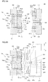
- FIG. 2A is a side cross-sectional view for explaining a mold open state before molding of the first and second molds incorporated in the molding apparatus of FIG. 1, and FIG. 2B is a mold of the first and second molds. It is a sectional side view explaining a closed state.
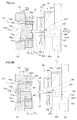
- FIG. 3A is a side cross-sectional view for explaining the mold opening state after the first and second molds are molded, and FIG. 3B is a side cross-sectional view for explaining the protrusion of the molded product.
- FIG. 4A is a side cross-sectional view for explaining the molded product chuck by the take-out device, and FIG.
- FIG. 4B is a side cross-sectional view for explaining the take-out of the molded product by the take-out device.
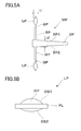
- FIG. 5A is a side sectional view of a molded product molded by the first and second molds
- FIG. 5B is a side view of the optical element.
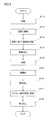
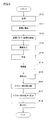
- It is a flowchart explaining the manufacturing method using the shaping
- It is a conceptual diagram explaining the principal part of the shaping
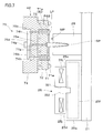
- an apparatus 100 for manufacturing a thermoplastic resin product is an injection molding machine 10 that is a main body part that performs injection molding to produce a molded product MP, and for taking out the molded product MP from the injection molding machine 10.
- a take-out device 20 that is an attached portion and a control device 30 that comprehensively controls the operation of each part of the manufacturing apparatus 100 are provided.
- the injection molding machine 10 is a horizontal molding machine and includes a molding die 40, a fixed platen 11, a movable platen 12, a mold clamping plate 13, an opening / closing drive device 15, and an injection device 16.
- the injection molding machine 10 clamps both molds 41 and 42 by sandwiching a first mold 41 and a second mold 42 constituting the molding mold 40 between the fixed platen 11 and the movable platen 12. This enables molding.
- the fixed platen 11 is fixed to the approximate center of the support frame 14 so as to face the movable platen 12, and supports the take-out device 20 on the top thereof.
- the inner side 11a of the heel fixed platen 11 faces the inner side 12a of the movable platen 12, and supports the first mold 41 in a detachable manner.
- the fixed platen 11 is formed with an opening 11b through which a later-described resin supply nozzle 16d is passed. Note that the fixed platen 11 is fixed to the mold clamping plate 13 via a tie bar so that it can withstand the pressure of mold clamping during molding.
- the movable platen 12 is supported by a linear guide 15a, which will be described later, so as to be movable back and forth with respect to the fixed platen 11.
- the inner side 12a of the movable platen 12 faces the inner side 11a of the fixed platen 11, and supports the second mold 42 in a detachable manner.
- an ejector driving unit 45 is incorporated in the movable platen 12. The ejector driving unit 45 is for extruding the molded product MP in the second mold 42 toward the first mold 41 in order to release the molded product MP.
- the mold clamping machine 13 is fixed to the end of the support frame 14.
- the mold clamping machine 13 supports the movable board 12 from the back via the power transmission part 15d of the opening / closing drive device 15 at the time of mold clamping.
- the opening / closing drive device 15 includes a linear guide 15a, a power transmission unit 15d, and an actuator 15e.
- the linear guide 15 a supports the movable platen 12 and enables the movable platen 12 to smoothly reciprocate with respect to the advancing and retreating direction with respect to the fixed platen 11.
- the power transmission unit 15 d expands and contracts in response to the driving force from the actuator 15 e that operates under the control of the control device 30.
- the movable platen 12 moves forward and backward freely with respect to the mold clamping plate 13, close to or away from the mold clamping plate 13.
- the fixed platen 11 and the movable platen 12 can be brought close to or separated from each other, and the first die 41 and the second die 42 can be closed (including clamping) or opened. it can.
- the injection device 16 includes a cylinder 16a, a raw material storage unit 16b, a screw drive unit 16c, and the like.
- the injection device 16 operates at an appropriate timing under the control of the control device 30, and is a nozzle for injecting a thermoplastic resin (molten resin) that is melted in the cylinder 16a and temperature-controlled by the heater 16h. Inject from 16d.
- the injection device 16 brings the nozzle 16d into contact with a sprue bush 65 (see FIG. 2B and the like) to be described later through the opening 11b of the stationary platen 11. .
- the molten resin held above the glass transition point can be supplied to the flow path space FC (see FIG. 2B and the like) described later at a desired timing and pressure.
- the injection device 16 is a supply device that supplies a thermoplastic resin to a molding die (molding device) 40 having a first die 41 and a second die 42.
- a mold temperature controller 46 attached to the injection molding machine 10 circulates a temperature-controlled heat medium in both molds 41 and 42. Thereby, at the time of shaping
- the take-out device 20 includes an arm 21 that can hold the molded product MP and a three-dimensional drive device 22 that moves the arm 21 three-dimensionally.
- the take-out device 20 operates at an appropriate timing under the control of the control device 30, and remains in the second die 42 after the first die 41 and the second die 42 are separated and opened. It has the role of gripping the molded product MP and carrying it out.
- a chuck device 25 is provided at the lower end of the arm 21 in the take-out device 20 and holds the sprue portion SP and the like of the molded product MP.
- the control device 30 includes an opening / closing control unit 31, an injection device control unit 32, an ejector control unit 33, and a take-out device control unit 34.
- the opening / closing control unit 31 enables the molds 41 and 42 to be closed, clamped, opened, and the like by operating the actuator 15e.
- the injection device control unit 32 injects resin at a desired temperature and pressure into a molding space CV (see FIG. 2B) formed between both molds 41 and 42 by operating the screw driving unit 16c, the heater 16h, and the like.
- the ejector control unit 33 operates the ejector driving unit 45 to push out the molded product MP remaining in the second mold 42 when the mold is opened from the second mold 42 to release the mold.
- the take-out device control unit 34 operates the take-out device 20 to grip the molded product MP remaining in the second mold 42 after mold opening and release, and to perform additional molding on the molded product MP.
- the molded product MP after additional molding is carried out of the injection molding machine 10.
- dies 40 can be reciprocated to AB direction. As shown in FIG. 2B, the second mold 42 is moved toward the first mold 41, and both molds 41, 42 are mold-matched with the mold-matching surfaces PS1, PS2 and clamped. A molding space CV for molding the part LP (lens) and a channel space FC that is a channel for supplying resin to the molding space CV are formed.
- the first mold 41 includes a mold plate 61 disposed on the inner side, that is, the mold mating surface PS1 side, a plurality of core molds 62 embedded in the mold plate 61, and an attachment disposed on the outer side, that is, the fixed platen 11 side in FIG. Plate 64.
- a sprue bushing 65 is provided in association with the first mold 41.
- the nozzle 16d provided at the tip of the cylinder 16a is brought into contact with the inlet of the sprue bush 65 on the fixed platen 11 side (see FIG. 1) when the molten resin is supplied from the injection device 16 into the molding die 40.
- the template 61 of the first mold 41 is a metal plate-like member, and includes a plurality of core holes 61a into which the plurality of core dies 62 are inserted, and a sprue hole 66 for allowing resin to flow into the molding space CV.
- the core holes 61a are provided at, for example, four locations on the circumference centered on the sprue hole 66.
- the sprue hole 66 has a conical inner surface and extends substantially parallel to the AB direction which is the mold opening / closing direction and penetrates the first mold 41.
- thermometer 52 for heating, a heater for heating (not shown), and the like are incorporated.
- the core mold 62 is a cylindrical member extending in the AB direction, and a transfer recess 61e is formed on the tip surface thereof.
- the transfer recess 61e has a mirror-like first transfer surface S1, and when the product portion LP of the molded product MP is a component of an imaging lens or an objective lens, the transfer recess 61e has a shape corresponding to the optical surface of these objects. Processed.
- the first transfer surface S1 may be a surface provided with a fine structure.
- the mounting plate 64 is a metal plate-like member, and supports the template 61 from behind. That is, the mounting plate 64 supports the template 61 from the opposite side (back side) of the die-matching surface PS1. Although illustration is omitted, the mounting plate 64 has a plurality of fastening members for fixing the mounting plate 64 itself to the fixed platen 11.
- the second mold 42 includes a mold plate 71 disposed on the inner side, that is, the mold mating surface PS2 side, a plurality of core molds 72 embedded in the mold plate 71, and an attachment disposed on the outer side, that is, the movable platen 12 side in FIG.
- a plate 74 and an ejector member 75 formed to be embedded in the mounting plate 74 are provided.
- the template 71 of the second mold 42 is a metal plate-like member, a plurality of core holes 71a into which the plurality of core dies 72 are inserted, a cold slug 71b facing the tip of the sprue hole 66, A runner recess 71f branched from the cold slug 71b and extending in a plurality of directions.
- a plurality of core holes 71 a are provided to face the core holes 61 a provided in the template 61 of the first mold 41.
- the runner recesses 71f extend radially from the cold slugs 71b toward the transfer recesses 71e.
- the runner recess 71f forms a runner RB in the flow path space FC that communicates with the molding space CV when the first and second molds 41 and 42 are closed (see FIG. 2B).
- the core mold 72 is a cylindrical member extending in the AB direction, and a transfer recess 71e is formed on the tip surface thereof.
- the transfer recess 71e formed in the core mold 72 and the transfer formed in the core mold 62 embedded in the mold plate 61 of the first mold 41.
- a molding space CV is formed between the recesses 61e.
- the transfer recess 71e has a mirror-like second transfer surface S2, and when the product portion LP of the molded product MP is a component of the imaging lens or objective lens, the transfer recess 71e has a shape corresponding to the optical surface of these objects.
- the second transfer surface S2 may be a surface provided with a fine structure.
- a pin hole 71g through which an ejector pin 75a constituting the ejector member 75 is passed is also formed in the template 71.
- thermometer 52 for heating, a heater for heating (not shown), and the like are incorporated.
- the mounting plate 74 is a metal plate-like member, and supports the template 71 from behind.
- the mounting plate 74 includes pin holes 74g and 74h through which the ejector pins 75a and 75b constituting the ejector member 75 are passed. Although illustration is omitted, the attachment plate 74 has a plurality of fastening members for fixing the attachment plate 74 itself to the movable platen 12.
- the ejector member 75 is a mechanical mechanism having ejector pins 75a and 75b and an ejector plate 75d, and operates by being driven by the ejector driving unit 45 of FIG.
- the ejector pins 75a and 75b are connected to the ejector plate 75d, and can be moved forward and backward collectively in the pin holes 71g of the template 71 and the pin holes 74g and 74h of the mounting plate 74.
- the ejector pins 75a and 75b move forward.
- the central ejector pin 75a protrudes from the bottom of the cold slug 71b of the template 71, and the peripheral ejector pin 75b pushes the core mold 72. Press to project from the mold matching surface PS2.
- the ejector member 75 is set in the retracted state, the ejector pins 75a and 75b are retracted, and the central ejector pin 75a is retracted into the bottom of the cold slug 71b of the template 71, and the peripheral ejector pins 75b are similarly.
- the core mold 72 is allowed to retract by retracting.
- the core mold 72 has a structure with an unillustrated spring or the like attached thereto, and when it receives no urging force to advance from the ejector pin 75b, it retracts and is housed in the core hole 71a.
- die 42 fit the positioning fitting part 41x provided in the 1st metal mold
- the chuck device 25 includes a support base portion 25a and first and second chuck members 25c and 25d.
- the support base 25a includes a chuck driving unit 25f that causes the pair of chuck members 25c and 25d to perform a clamping operation. Both chuck members 25c and 25d can be displaced in the vertical CD direction by being driven by a chuck drive section 25f.
- Both chuck members 25c and 25d are driven by the chuck drive unit 25f and operate in synchronization. Both chuck members 25c and 25d can grip the sprue portion SP of the molded product MP by approaching each other, and can release the grip of the sprue portion SP by separating from each other synchronously. Inner side surfaces IS1 and IS2 of both chuck members 25c and 25d are formed surfaces, and shape transfer, that is, molding is performed on the surfaces SP1 and SP2 of the sprue portion SP that is still softened.
- a cooling device 25j is built in each chuck member 25c, 25d, and cools the chuck members 25c, 25d to a predetermined temperature lower than the glass transition point.
- the cooling device 25j can be composed of, for example, a Peltier element.
- the cooling device 25j can be replaced with a heat sink structure, a heat pipe, a cold water pipe, or the like, or can be replaced with a fan or other air cooling device.
- a plurality of runner portions RP extends around the sprue portion SP, and a product portion LP is formed on the extension of the runner portion RP.
- the runner part RP and the sprue part SP excluding the product part LP in the molded product MP are non-product parts.
- Each product part LP is obtained by cutting the gate GP at the boundary between the runner part RP and the product part LP.
- the maximum thickness t1 of the product portion LP in the optical axis direction is smaller than the maximum thickness t2 of the sprue portion SP in the diameter direction. For this reason, when the molded product MP is manufactured, the product portion LP is cooled earlier than the sprue portion SP, and the product portion LP can be easily cooled to a temperature lower than that of the sprue portion SP. Specifically, for example, the product portion LP is easily brought into a temperature state lower than the glass transition point of the molten resin, and the sprue portion SP is easily brought into a temperature state equal to or higher than the glass transition point of the molten resin.
- the product part LP has an optical function part OP and a flange part FL.
- the optical function portion OP is formed by the first optical surface OS1 formed by, for example, the transfer recess 61e among the transfer recesses 61e, 71e provided in the molding die 40 of FIG. And a second optical surface OS2.
- the product part LP is an imaging lens mounted on, for example, an imaging device (including those mounted on a portable terminal such as a notebook PC).
- the product portion LP can also be an objective lens for a thick-type optical pickup device having a large protrusion on the first optical surface OS1 side.
- the product unit LP enables reading or writing of optical information corresponding to a BD (Blu-ray (registered trademark) Disc) having a wavelength of 405 nm and a numerical aperture (NA) of 0.85, for example.
- the molded product MP including the product part LP is formed of an optical resin.
- the optical resin for example, COC (cycloolefin copolymer), PMMA (polymenthyl methacrylate) and the like are used.
- the mold temperature controller 46 heats both molds 41 and 42 to a temperature suitable for molding (step S10).
- the temperature of the mold surface forming the molding space CV in both the molds 41 and 42 and the temperature in the vicinity thereof are, for example, 20 ° C. lower than the glass transition point of the molten resin supplied from the injection device 16. In this state, the temperature is kept at a temperature lower than the glass transition point.
- the opening / closing drive device 15 is operated to advance the movable platen 12 to start mold closing (step S11).
- the movable platen 12 moves to the fixed platen 11 side to the die contact position where the first die 41 on the fixed side and the second die 42 on the movable side come into contact with each other.
- the mold closing is completed.
- mold clamping is performed to clamp the first mold 41 and the second mold 42 with necessary pressure (step S12).
- the injection device 16 is operated to bring the nozzle 16d into contact with the sprue bushing 65 of the first mold 41 and to inject the molten resin into the molding space CV with a necessary pressure.
- the temperature of the molten resin supplied from the injection device 16 is set to a temperature equal to or higher than the glass transition point, for example, 100 ° C. to 150 ° C. higher than the glass transition point.
- the injection molding machine 10 After the molding space CV is filled with resin, the injection molding machine 10 maintains the resin pressure in the molding space CV. At this time, the mold temperature controller 46 appropriately heats the molding space CV and the flow path space FC (see FIG. 2B) through which resin flows into the molding space CV, and the molten resin supplied from the injection device 16. Is moderately cooled, and moderate decooling of the resin in the molding space CV can be achieved. After the molten resin is introduced into the molding space CV, the molten resin in the molding space CV is gradually cooled by heat dissipation, so that the temperature of the resin in the molding space CV, that is, the product part LP is lower than the glass transition point. And wait for the molding to be completed (step S14).
- the temperature of the product part LP becomes a temperature lower than the glass transition point, it is considered that the molding is completed, and the temperature of the resin in the sprue hole 66, that is, the sprue part SP is lower than the glass transition point. I do not wait for that. That is, it does not wait until the entire molded product MP reaches a temperature lower than the glass transition point, but the molding is completed when the sprue portion SP is at a temperature equal to or higher than the glass transition point as will be described later.
- the opening / closing drive device 15 is operated to perform mold opening for retracting the movable platen 12 (step S15).
- the second mold 42 is retracted, and the first mold 41 and the second mold 42 are separated.
- the molded product MP that is, the product part LP, the runner part RP, and the like are released from the first mold 41 while being held by the second mold 42.
- step S16 the ejector driving unit 45 is operated, and the molded product MP including the product part LP is ejected by the advancement of the ejector pins 75a and 75b (step S16).
- the runner portion RP and the like of the molded product MP are pushed out to the first mold 41 side and released from the second mold 42.
- the take-out device 20 is operated to cause the chuck device 25 to perform an operation of gripping the molded product MP locked to the second mold 42.
- the removal of the molded product MP is started by the operation of causing the chuck device 25 to grip the molded product MP.
- the sprue portion SP of the molded product MP is at a temperature higher than the glass transition point, as shown in FIG. 4A, the surface of the sprue portion SP is formed by the inner side surfaces IS1, IS2 of both chuck members 25c, 25d.
- the shapes of the inner side surfaces IS1, IS2 are transferred to the SP1, SP2, and additional or auxiliary molding is performed on the sprue portion SP (step S17).
- the sprue portion SP is solidified with molding.
- the temperature of the sprue portion SP when the sprue portion SP is sandwiched between the chuck members 25c and 25d that is, the temperature of the sprue portion SP during additional molding is equal to or higher than the glass transition point, and is added to the glass transition point by 50 ° C. It is assumed that the temperature is lower than
- the temperature of the sprue portion SP at the time of additional molding is more preferably not more than a temperature obtained by adding 20 ° C. to the glass transition point, and further preferably not more than a temperature obtained by adding 10 ° C. to the glass transition point.
- the take-out device 20 is operated to completely separate the molded product MP from the second mold 42, and the molded product MP is taken out between the first and second molds 41 and 42. To the outside (step S18).
- the product part LP is in a temperature state lower than the glass transition point, and the non-product part (including the sprue part SP and the runner part RP) is higher than the glass transition point. Since the removal of the molded product MP is started in the temperature state, it is possible not only to prevent the deformation of the product part LP and the occurrence of internal distortion, but also to shorten the molding cycle time by shortening the cooling process. Further, according to the manufacturing method and the like, since the molded product MP can be molded when the sprue part SP which is a non-product part is taken out, the molded product MP can be accurately taken out by the sprue part SP which is a non-product part.
- the sprue portion SP which is a non-product portion
- the sprue portion SP which is a non-product portion
- the product portion LP is excessively cooled in the mold and shrinkage distortion occurs. It is possible to prevent the resin from flowing into the molding space CV, which is the product space, and to ensure good transferability with respect to the product shape.
- the arm 21 of the take-out device 20 is provided with a heating device 28 adjacent to the chuck device 25.
- the eaves heater 28 incorporates an infrared heater, for example, but can also send hot air.
- the sprue portion SP of the molded product MP remaining in one of the first and second molds 41 and 42 after the mold 40 is opened is heated from the surroundings, so that the glass transition point is reached. It is above and can be set as the state below the temperature which added 50 degreeC to the glass transition point.
- FIG. 8 is a diagram for explaining the manufacturing method of the second embodiment.
- the sprue portion SP is heated using the heating device 28 provided in the take-out device 20 of FIG. (Step S26). Accordingly, the sprue portion SP can be softened, and the chuck members SP can be sandwiched between the first and second chuck members 25c and 25d in the subsequent additional or auxiliary molding process.
- the shape of the inner side surfaces IS1, IS2 can be transferred to the surfaces SP1, SP2 of the sprue portion SP by the inner side surfaces IS1, IS2 of 25d (step S17).
- the first and second chuck members 325c and 325d of the chuck device 25 are provided with molding pieces 25m and 25n, respectively.
- the inner surfaces (transfer surfaces) IS1 and IS2 of the molding piece portions 25m and 25n are brought into the surfaces SP1 and SP2 of the sprue portion SP.
- the shape of the side surfaces IS1, IS2 can be transferred.
- the inner side surfaces IS1, IS2 are curved so as to undulate, and a curved portion can be formed in the sprue portion SP.
- the sprue portion SP is cooled and solidified, so that the gripping of the sprue portion SP by both chuck members 325c and 325d can be ensured. This facilitates handling of the molded product MP when shifting to the processing step of cutting the product portion LP or during the processing step.
- the molding piece portions 25m and 25n may be exchangeable.
- the fourth embodiment of the method and apparatus for producing a thermoplastic resin product according to the present invention will be described below.
- the manufacturing method of the fourth embodiment is a modification of the manufacturing method of the first and third embodiments, and matters not specifically described are the same as those of the manufacturing method of the first embodiment.
- the first and second chuck members 425c and 425d of the chuck device 25 are provided with molding pieces 25m and 25n, respectively.
- the inner side surfaces (transfer surfaces) IS1 and IS2 of the molding piece portions 25m and 25n are brought into the surfaces SP1 and SP2 of the sprue portion SP.
- the shape of the side surfaces IS1, IS2 can be transferred.
- the inner side surfaces IS1, IS2 are curved so as to be twisted, and a hook-like portion can be formed in the sprue portion SP.
- the sprue portion SP is cooled and solidified, so that the gripping of the sprue portion SP by both the chuck members 425c and 425d can be ensured.
- the sprue portion SP since the sprue portion SP has a bowl shape, the molded product MP can be suspended. As a result, it is possible to reduce defects such as takeout defects and misalignment of gate cuts in processing steps.
- the manufacturing method etc. of the manufacturing method of a thermoplastic resin product were demonstrated according to embodiment, this invention is not limited to the above thing, A various deformation
- the shape of the molding space CV provided in the injection mold including the first mold 41 and the second mold 42 can be various shapes. That is, the shape of the molding space CV formed by the transfer recesses 61e, 71e, etc. is merely an example, and the product portion LP can be a variety of optical elements, not limited to lenses. Good.
- the sprue portion SP is formed by gripping the sprue portion SP by the chuck device 25, but after the runner portion RP is gripped by the chuck device 25 and the runner portion RP is formed. It is also possible to carry out the molded product MP.
- the horizontal manufacturing apparatus 100 is used, but a vertical molding apparatus may be used.
- the molded product MP may be deformed due to, for example, a cooling state regardless of gravity, and solidification by molding of the sprue portion SP or the like softened by the chuck device 25 is meaningful from the viewpoint of improving throughput or the like.
- the molded product MP is ejected by the ejector pins 75 a and 75 b and released from the second mold 42, but may be released by the take-out device 20.
- the molded product MP remains in the second mold 42, but may remain in the first mold 41.
- the take-out device 20 forms the non-product part such as the runner part RP and the sprue part SP of the molded product MP remaining in the first mold 41 and takes out the molded product MP.
Abstract
簡易な手法で優れた熱可塑性樹脂製品の製造方法及び装置を提供することを目的とする。製品部LPがガラス転移点より低い温度状態であり、かつ、非製品部であるスプルー部SPがガラス転移点以上に高い温度状態であるときに、成形品MPの取り出しを開始するので、製品部LPの変形や内部歪みの発生を防止できるだけでなく、冷却工程の短縮によって成形のサイクルタイムを短くすることができる。また、上記製造方法等によれば、非製品部であるスプルー部SPが成形品MPを取り出す際に成形されるので、非製品部であるスプルー部SPによる成形品MPの取り出しが正確で確実になり、取り出し工程で非製品部あるスプルー部SPが意図しない形状に変形し又は破損することを防止できる。
Description
本発明は、光学素子その他の熱可塑性樹脂製品を成形によって得る熱可塑性樹脂製品の製造方法及び装置に関する。
射出成形には、製品部、ランナー、スプルー等に対応する転写形状が形成された型空間を設けた金型装置に溶融樹脂を流入させる射出工程と、型空間に流入した溶融樹脂を金型装置内で冷却する冷却工程と、金型装置を開いて成形品を開放する型開き工程と、成形品のうちスプルーを取出装置のチャック部で掴んで成形品を取り出す取り出し工程とが含まれる。 なお、取り出し後の成形品に対しては、ゲートカットその他の処理工程が施される場合もある。
成形品のスプルーの形状は、金型装置から離型しやすい円錐形状であることが多く、強い力で掴まないと滑ってしまい、安定してスプルー部を掴むことが難しいという問題がある。 これは、取り出し工程における取り出し不良や処理工程におけるゲートカット位置のズレなどの不良に繋がる。
また、冷却工程において溶融樹脂を冷却し固化させるが、十分に冷却し過ぎると、金型部材と樹脂との収縮率の違いにより成形品を歪ませてしまう。逆に、冷却が不足すると、成形品の樹脂温度がガラス転移点以上となり、成形品が柔らかいままで型開き工程に入る。この場合、型開き工程において、成形品の形状が変形し易く、特に溶融樹脂の流入口付近のスプルー部やランナー部が変形し易く、極端な場合はスプルー部がちぎれてしまう。例えば取り出し工程でチャック部によって掴むはずのスプルー部が変形してしまうと、取り出しが困難となり取り出し不良となってしまう。
冷却時間を短縮する方法として、スプルー部を強制的に冷却する方法が特許文献1で提案されている。スプルー部の周りに冷却用の媒体を流すことでスプルー部の熱を奪うといった構造である。このような構造で冷却スピードを上げる場合、溶融樹脂が製品部に達するまでにスプルー部で熱が奪われてしまうため、溶融樹脂が金型の製品部に対応する製品空間に流入するまでの間に冷めてしまい、製品形状の転写性が悪くなるヒケ、ウェルド等の問題が発生する。これに対しては、樹脂の温度を高めに設定することで製品部を冷めにくくすることもできるが、黄変等の樹脂の劣化、黒ゴミ等の炭化物の混入といった不良の発生に繋がる。
また、製品部分をガラス転移点以上で型開きすることが特許文献2で提案されているが、製品部分をガラス転移点以上で型開きする場合、離型時に製品内部に歪を生じさせるおそれがある。特に光学素子等の光を透過させる製品の場合、内部歪によって光が複屈折等の作用を受けて歪んだ状態で透過してしまうので、成形品がガラス転移点以上で型開きされる場合、良好な製品を成形することは非常に困難である。撮像レンズや光ピックアップ装置用の対物レンズのような光学素子において、ウェルド、ヒケ、黄変、黒ゴミ等の発生は、性能を悪化させる原因に繋がるため、回避する必要がある。
本発明は、成形品の安定した取り出しが可能で、成形品に収縮歪みが発生することを回避しつつスプルー部を十分に固化させて成形品の確実な取り出しを可能とし、製品形状に関して良好な転写性を確保することができ、成形品に内部歪み等を発生させにくい、熱可塑性樹脂製品の製造方法及び装置を提供することを目的とする。
上記目的を達成するため、本発明に係る熱可塑性樹脂製品の製造方法は、第1の金型と第2の金型とを備える金型装置に熱可塑性樹脂を供給することによって、製品部と、第1の金型と第2の金型との型閉じによって形成される熱可塑性樹脂用の流路に対応して製品部から延びる非製品部とを含む成形品を成形する熱可塑性樹脂製品の製造方法であって、製品部がガラス転移点より低い温度状態であり、かつ、非製品部がガラス転移点以上に高い温度状態であるときに、金型装置からの成形品の取り出しを開始する。ここで、成形品とは、スプルー部、ランナー部、製品部等の熱可塑性樹脂を固化させた全ての部分を意味する。また、製品部は、最終製品(例えば光学素子)となる部分であり、ゲート部よりも先端側の部分を意味する。
上記製造方法によれば、非製品部がガラス転移点以上に高い温度状態であるときに、成形品の取り出しを開始するので、冷却工程の短縮によって成形のサイクルタイムを短くすることができるだけでなく、成形品の取り出し開始時に製品部がガラス転移点より低い温度状態であるので、製品部の変形や内部歪みの発生を防止できる。
本発明の具体的な態様又は側面では、上記製造方法において、非製品部を成形品を取り出す際に成形するので、非製品部による成形品の取り出しが正確で確実になり、取り出し工程で非製品部が意図しない形状に変形し又は破損することを防止できる。ここで、取り出し工程において非製品部がガラス転移点以上に高い温度状態であるので、結果的に製品部が金型内で過剰に冷却されて収縮歪みが発生することを防止でき、製品空間への樹脂の流入を容易にして製品形状に関して良好な転写性を確保することができる。
本発明の別の側面では、非製品部がガラス転移点に50℃加算した温度以下であるときに、成形品を取り出す。この場合、非製品部が過度に軟化することを回避しやすくなり、非製品部の成形が比較的簡易になる。また、黄変等の樹脂の劣化、黒ゴミ等の炭化物の混入といった不良の発生を確実に防止できる。 なお、成形品を取り出す際の非製品部の温度は、より好ましくはガラス転移点に20℃加算した温度以下とする。成形品を取り出す際の非製品部の温度は、さらに好ましくはガラス転移点に10℃加算した温度以下とする。
本発明のさらに別の側面では、成形品を取り出すための取出装置に冷却装置を組み込んで、当該冷却装置によって成形品の非製品部を冷却する。この場合、非製品部を冷却することで非製品部の形状を迅速に安定化させることができる。
本発明のさらに別の側面では、成形品を取り出すための取出装置にコマ部(形状転写部)を設けて、成形品の非製品部のうちスプルー部にコマ部の形状を転写する。この場合、取出装置による成形品の把持の時にスプルー部にコマ部の形状を転写することになり、成形品の迅速な取り出しが可能になる。
本発明のさらに別の側面では、成形品の非製品部の最大厚みが、製品部の最大厚みよりも大きい。この場合、製品部がガラス転移点より低い温度状態であり、かつ非製品部がガラス転移点以上に高い温度状態であるといった条件を作り出しやすくなり、成形品の取り出しタイミング等の確保や調整が容易となる。
本発明のさらに別の側面では、金型装置が、ガラス転移点より低い温度に設定され、ガラス転移点以上の高い温度の熱可塑性樹脂を金型装置の流路に供給する。この場合、製品空間に流入した樹脂をガラス転移点より低い温度に冷却しつつ、非製品部の樹脂をガラス転移点以上に高い温度に保持しやすくなる。
本発明のさらに別の側面では、金型装置の型開き後に第1及び第2の金型うち一方に残った成形品をエジェクトした直後のタイミングで、成形品を取り出すための取出装置によって非製品部を把持して成形を行う。この場合、製品部に歪みや変形が発生する可能性を低減でき、かつ、非製品部が比較的高温で非製品部の成形に適する。
本発明のさらに別の側面では、金型装置の型開き後に第1及び第2の金型うち一方に残った成形品の非製品部を加熱することによってガラス転移点以上の高い温度まで加熱したタイミングで、成形品を取り出すための取出装置によって非製品部を把持して成形を行う。この場合、非製品部を強制的に成形に適する温度にでき、非製品部の成形が容易となる。
上記目的を達成するため、本発明に係る熱可塑性樹脂製品の製造装置は、第1の金型と第2の金型とを有する金型装置と、金型装置に熱可塑性樹脂を供給する供給装置と、金型装置によって成形された成形品を取り出す取出装置とを備える熱可塑性樹脂製品の製造装置であって、成形品は、製品部と、第1の金型と第2の金型との型閉じによって形成される熱可塑性樹脂用の流路に対応して製品部から延びる非製品部とを含み、取出装置は、製品部がガラス転移点より低い温度状態であり、かつ、非製品部がガラス転移点以上に高い温度状態であるときに、成形品の取り出しを開始する。
上記熱可塑性樹脂製品の製造装置によれば、取出装置が、製品部がガラス転移点より低い温度状態であり、かつ、非製品部がガラス転移点以上に高い温度状態であるときに、成形品の取り出しを開始するので、製品部の変形や内部歪みの発生を防止できる。また、上記製造装置によれば、非製品部を成形品を取り出す際に成形することもできる。この場合、非製品部による成形品の取り出しが正確で確実になり、取り出し工程で非製品部が意図しない形状に変形し又は破損することを防止できる。ここで、取り出し工程において非製品部がガラス転移点以上に高い温度状態であるので、結果的に製品部が金型内で過剰に冷却されて収縮歪みが発生することを防止でき、製品空間への樹脂の流入を容易にして製品形状に関して良好な転写性を確保することができる。
〔第1実施形態〕
以下、本発明の第1実施形態に係る熱可塑性樹脂製品の製造方法及び装置について、図面を参照しつつ説明する。
以下、本発明の第1実施形態に係る熱可塑性樹脂製品の製造方法及び装置について、図面を参照しつつ説明する。
図1に示すように、熱可塑性樹脂製品の製造装置100は、射出成形を行って成形品MPを作製する本体部分である射出成形機10と、射出成形機10から成形品MPを取り出すための付属部分である取出装置20と、製造装置100を構成する各部の動作を統括的に制御する制御装置30とを備える。
射出成形機10は、横型の成形機であり、成形金型40と、固定盤11と、可動盤12と、型締め盤13と、開閉駆動装置15と、射出装置16とを備える。射出成形機10は、固定盤11と可動盤12との間に成形金型40を構成する第1金型41と第2金型42とを挟持して両金型41,42を型締めすることにより成形を可能にする。
固定盤11は、可動盤12に対向して支持フレーム14の略中央に固定され、取出装置20をその上部に支持する。 固定盤11の内側11aは、可動盤12の内側12aに対向しており、第1金型41を着脱可能に支持している。固定盤11には、後述する樹脂供給用のノズル16dを通す開口11bが形成されている。なお、固定盤11は、タイバーを介して型締め盤13に固定されており、成形時の型締めの圧力に耐え得るようになっている。
可動盤12は、後述するリニアガイド15aによって固定盤11に対して進退移動可能に支持されている。可動盤12の内側12aは、固定盤11の内側11aに対向しており、第2金型42を着脱可能に支持している。なお、可動盤12には、エジェクター駆動部45が組み込まれている。このエジェクター駆動部45は、第2金型42内の成形品MPを離型するために第1金型41側に押し出すものである。
型締め盤13は、支持フレーム14の端部に固定されている。型締め盤13は、型締めに際して、開閉駆動装置15の動力伝達部15dを介して可動盤12をその背後から支持する。
開閉駆動装置15は、リニアガイド15aと、動力伝達部15dと、アクチュエーター15eとを備える。リニアガイド15aは、可動盤12を支持しつつ、固定盤11に対する進退方向に関して可動盤12の滑らかな往復移動を可能にしている。 動力伝達部15dは、制御装置30の制御下で動作するアクチュエーター15eからの駆動力を受けて伸縮する。これにより、型締め盤13に対して可動盤12が近接したり離間したり自在に進退移動する。結果的に、固定盤11と可動盤12とを互いに近接又は離間させることができ、第1金型41と第2金型42との型閉じ(型締めを含む)又は型開きを行うことができる。
射出装置16は、シリンダー16a、原料貯留部16b、スクリュー駆動部16c等を備える。射出装置16は、制御装置30の制御下で適当なタイミングで動作するものであり、シリンダー16a内で溶融されヒーター16hによって温度制御された状態の熱可塑性樹脂(溶融樹脂)を樹脂射出用のノズル16dから射出する。射出装置16は、第1金型41と第2金型42とを型締めした状態において、固定盤11の開口11bを介して後述するスプルーブッシュ65(図2B等参照)にノズル16dを接触させる。これにより、後述する流路空間FC(図2B等参照)に対してガラス転移点以上に保持された溶融樹脂を所望のタイミング及び圧力で供給することができる。すなわち、射出装置16は、第1金型41と第2金型42とを有する成形金型(金型装置)40に熱可塑性樹脂を供給する供給装置である。
射出成形機10に付随して設けられた金型温度調節機46は、両金型41,42中に温度制御された熱媒体を循環させる。これにより、成形時に両金型41,42の温度を溶融樹脂のガラス転移点より低い適当な冷却温度に保つことができる。
取出装置20は、成形品MPを把持することができるアーム21と、アーム21を3次元的に移動させる3次元駆動装置22とを備える。取出装置20は、制御装置30の制御下で適当なタイミングで動作するものであり、第1金型41と第2金型42とを離間させて型開きした後に、第2金型42に残る成形品MPを把持して外部に搬出する役割を有する。取出装置20のうちアーム21の下端には、チャック装置25が設けられており、成形品MPのスプルー部SP等を把持する。
制御装置30は、開閉制御部31と、射出装置制御部32と、エジェクター制御部33と、取出装置制御部34とを備える。開閉制御部31は、アクチュエーター15eを動作させることによって両金型41,42の型閉じ、型締め、及び型開き等を可能にする。射出装置制御部32は、スクリュー駆動部16c、ヒーター16h等を動作させることによって両金型41,42間に形成された成形空間CV(図2B参照)中に所望の温度及び圧力で樹脂を注入させる。エジェクター制御部33は、エジェクター駆動部45を動作させることによって型開き時に第2金型42に残る成形品MPを第2金型42内から押し出させて離型を行わせる。取出装置制御部34は、取出装置20を動作させることによって型開き及び離型後に第2金型42に残る成形品MPを把持するとともに成形品MPに対して追加的な成形を行わせ、かかる追加的な成形後の成形品MPを射出成形機10外に搬出させる。
以下、図2A等を参照して、成形金型40について詳しく説明する。成形金型40のうち第2金型42は、AB方向に往復移動可能になっている。この第2金型42を第1金型41に向けて移動させ、両金型41,42を型合わせ面PS1,PS2で型合わせして型締めすることにより、図2Bに示すように、製品部LP(レンズ)を成形するための成形空間CVと、これに樹脂を供給するための流路である流路空間FCとが形成される。
第1金型41は、内側すなわち型合わせ面PS1側に配置される型板61と、型板61に埋め込まれる複数のコア型62と、外側すなわち図1の固定盤11側に配置される取付板64とを備える。また、第1金型41に付随して、スプルーブッシュ65が設けられている。スプルーブッシュ65の固定盤11側(図1参照)の入口には、射出装置16から成形金型40内に溶融樹脂を供給する際に、シリンダー16aの先端に設けたノズル16dを接触させる。
第1金型41のうち型板61は、金属製の板状の部材であり、複数のコア型62を挿入する複数のコア孔61aと、成形空間CVに樹脂を流入させるためのスプルー孔66とを備える。図示を省略するが、コア孔61aは、例えばスプルー孔66を中心とする円周上の4箇所に設けられている。スプルー孔66は、円錐状の内面を有し型開閉方向であるAB方向に略平行に延びて第1金型41を貫通している。
なお、型板61内部には、成形時及び取り出し時に金型の温度を適切な温度に保つため、図1の金型温度調節機46からの熱媒体を流通させる温調流路51、温度監視用の温度計52、加熱用のヒーター(不図示)等が組み込まれている。
コア型62は、AB方向に延びる円柱状の部材であり、その先端面には、転写凹部61eが形成されている。転写凹部61eは、鏡面状の第1転写面S1を有しており、成形品MPの製品部LPが撮像レンズや対物レンズの構成要素である場合、これら目的物の光学面に対応する形状に加工される。なお、第1転写面S1は、微細な構造が設けられた面となる場合もある。
取付板64は、金属製の板状の部材であり、型板61を背後から支持している。つまり、取付板64は、型板61を型合わせ面PS1の反対側(背後側)から支持する。なお、図示は省略するが、取付板64は、取付板64自体を固定盤11に固定するための複数の締結部材を有する。
第2金型42は、内側すなわち型合わせ面PS2側に配置される型板71と、型板71に埋め込まれる複数のコア型72と、外側すなわち図1の可動盤12側に配置される取付板74と、取付板74に埋め込むように形成されたエジェクター部材75とを備える。
第2金型42のうち型板71は、金属製の板状の部材であり、複数のコア型72を挿入する複数のコア孔71aと、スプルー孔66の先端に対向するコールドスラグ71bと、コールドスラグ71bから分岐されて複数方向に延びるランナー凹部71fとを備える。コア孔71aは、第1金型41の型板61に設けたコア孔61aに対向して複数設けられている。ランナー凹部71fは、コールドスラグ71bから各転写凹部71eに向けて放射状に延びている。ランナー凹部71fは、第1及び第2金型41,42を型閉じした際に、成形空間CVに連通する流路空間FCのランナーRBを形成する(図2B参照)。
コア型72は、AB方向に延びる円柱状の部材であり、その先端面には、転写凹部71eが形成されている。第1及び第2金型41,42を型閉じした際に、コア型72に形成された転写凹部71eと、第1金型41の型板61に埋め込まれたコア型62に形成された転写凹部61eとに挟まれて成形空間CVが形成される。転写凹部71eは、鏡面状の第2転写面S2を有しており、成形品MPの製品部LPが撮像レンズや対物レンズの構成要素である場合、これら目的物の光学面に対応する形状に加工される。なお、第2転写面S2は、微細な構造が設けられた面となる場合もある。型板71には、エジェクター部材75を構成するエジェクターピン75aを通すピン孔71gも形成されている。
なお、型板71内部には、成形時及び取り出し時に金型の温度を適切な温度に保つため、図1の金型温度調節機46からの熱媒体を流通させる温調流路51、温度監視用の温度計52、加熱用のヒーター(不図示)等が組み込まれている。
取付板74は、金属製の板状の部材であり、型板71を背後から支持している。取付板74は、エジェクター部材75を構成するエジェクターピン75a,75bを通すピン孔74g,74hを備える。なお、図示は省略するが、取付板74は、取付板74自体を可動盤12に固定するための複数の締結部材を有する。
エジェクター部材75は、エジェクターピン75a,75bと、エジェクター板75dとを有する機械的な機構であり、図1のエジェクター駆動部45に駆動されて動作する。エジェクターピン75a,75bは、エジェクター板75dに連結されており、型板71のピン孔71g及び取付板74のピン孔74g,74h内で一括して進退移動させることができる。エジェクター部材75を前進状態とした場合、エジェクターピン75a,75bが前進し、このうち中央のエジェクターピン75aが型板71のコールドスラグ71bの底部に突起し、周辺のエジェクターピン75bがコア型72を押して型合わせ面PS2から突出させる。逆に、エジェクター部材75を後退状態とした場合、エジェクターピン75a,75bが後退し、このうち中央のエジェクターピン75aが型板71のコールドスラグ71bの底部に引っ込み、周辺のエジェクターピン75bも同様に引っ込んでコア型72の後退を許容する。 なお、コア型72は、不図示のバネ等を付随させた構造を有しており、エジェクターピン75bから前進させる付勢力を受けなくなった場合、後退してコア孔71aの奥に収納される。
なお、第1金型41と第2金型42とは、第1金型41に設けた位置決め嵌合部41xと第2金型42に設けた位置決め嵌合部42xとを嵌合させることにより、型合わせ面PS1,PS2に垂直な方向の位置決めが可能になっている。
以下、図3B等を参照しつつ、取出装置20のアーム21の下端に設けたチャック装置25の詳細について説明する。チャック装置25は、支持基部25aと、第1及び第2チャック部材25c,25dとを備える。
支持基部25aは、一対のチャック部材25c,25dに挟持動作を行わせるチャック駆動部25f備える。両チャック部材25c,25dは、チャック駆動部25fに駆動されて上下のCD方向に変位可能である。
両チャック部材25c,25dは、チャック駆動部25fに駆動されて同期して動作する。両チャック部材25c,25dは、互いに近接することで成形品MPのスプルー部SPを把持することができ、同期して互いに離間することでスプルー部SPの把持を解除することができる。両チャック部材25c,25dの内側面IS1,IS2は、成形面となっており、まだ軟化した状態にあるスプルー部SPの表面SP1,SP2に対して形状の転写すなわち成形を行う。各チャック部材25c,25dの内部には、冷却装置25jが内蔵されており、チャック部材25c,25dをガラス転移点よりも低い所定の温度に冷却している。これにより、両チャック部材25c,25dに挟まれたスプルー部SPを急速に冷却してガラス転移点よりも低い温度とすることができ、形状転写後のスプルー部SPを迅速かつ十分に固化又は硬化させることができる。冷却装置25jは、例えばぺルチェ素子等で構成することができる。冷却装置25jは、ヒートシンク構造、ヒートパイプ、冷水管等に置き換えることができ、ファンその他の空冷装置に置き換えることもできる。
以下、図5A及び5Bを参照しつつ、上記製造装置100によって成形された成形品MP及び製品部LPについて説明する。図5Aに示すように、成形品MPにおいて、スプルー部SPを中心として複数のランナー部RPが延びており、ランナー部RPの延長上に製品部LPが形成されている。成形品MPのうち製品部LPを除いたランナー部RPやスプルー部SPは、非製品部である。ランナー部RPと製品部LPとの境界のゲートGPを切断することにより、個々の製品部LPを得る。なお、製品部LPの光軸方向の最大厚みt1は、スプルー部SPの直径方向の最大厚みt2よりも小さくなっている。このため、成形品MPの製造に際して、製品部LPの方がスプルー部SPよりも早く冷却され、製品部LPをスプルー部SPよりも低温とすることが容易となる。具体的には、例えば製品部LPを溶融樹脂のガラス転移点よりも低い温度状態とし、スプルー部SPを溶融樹脂のガラス転移点以上の温度状態とすることが容易となる。
図5Bに示すように、製品部LPは、光機能部OPとフランジ部FLとを有している。製品部LPのうち光機能部OPは、図2Aの成形金型40に設けた転写凹部61e,71eのうち例えば転写凹部61eによって形成される第1の光学面OS1と、例えば転写凹部71eによって形成される第2の光学面OS2とを有している。製品部LPは、例えば撮像装置(ノートPC等の携帯端末に搭載されるものを含む)に搭載される撮像レンズである。また、製品部LPは、第1光学面OS1側の突起が大きな肉厚型の光ピックアップ装置用の対物レンズとすることもできる。この場合、製品部LPは、例えば波長405nmで開口数(NA)0.85のBD(Blu-ray(登録商標) Disc)に対応した光情報の読み取り又は書き込みを可能にする。製品部LPを含む成形品MPは、光学用樹脂で形成されている。光学用樹脂として、例えばCOC(cycloolefin copolymer)、PMMA(polymenthyl methacrylate)等が用いられる。
以下、図6を参照しつつ製造装置100を用いた成形品MPすなわち製品部LPの製造方法について説明する。まず、金型温度調節機46により、両金型41,42を成形に適する温度まで加熱する(ステップS10)。これにより、両金型41,42において成形空間CVを形成する金型の表面やその近傍の温度を、射出装置16から供給される溶融樹脂のガラス転移点よりも例えば20℃低い温度以上であって同ガラス転移点より低い温度に加熱保持した状態とする。
次に、開閉駆動装置15を動作させ、可動盤12を前進させて型閉じを開始させる(ステップS11)。開閉駆動装置15の閉動作を継続することにより、固定側である第1金型41と可動側である第2金型42とが接触する型当たり位置まで可動盤12が固定盤11側に移動して型閉じが完了する。開閉駆動装置15の閉動作を更に継続することにより、図2Bに示すように、第1金型41と第2金型42とを必要な圧力で締め付ける型締めが行われる(ステップS12)。
次に、射出成形機10において、射出装置16を動作させて、ノズル16dを第1金型41のスプルーブッシュ65に接触させるとともに、成形空間CV中に必要な圧力で溶融樹脂を注入する射出を行わせる(ステップS13)。射出装置16から供給される溶融樹脂の温度は、ガラス転移点以上の温度例えばガラス転移点よりも100℃~150℃高い範囲に設定されている。
成形空間CVに樹脂が充填された後、射出成形機10は、成形空間CV中の樹脂圧を保つ。この際、金型温度調節機46により、成形空間CVやこの成形空間CVに樹脂を流入する流路空間FC(図2B参照)が適度に加熱されており、射出装置16から供給される溶融樹脂が緩やかに冷却され、成形空間CV内での樹脂の適度な除冷を達成することができる。溶融樹脂を成形空間CVに導入した後は、成形空間CV中の溶融樹脂が放熱によって徐々に冷却されるので、成形空間CV内の樹脂すなわち製品部LPの温度がガラス転移点よりも低い温度となって成形が完了するのを待つ(ステップS14)。なお、製品部LPの温度がガラス転移点よりも低い温度となった場合、成形が完了したものと考え、スプルー孔66内の樹脂すなわちスプルー部SPの温度がガラス転移点よりも低い温度となることを待たない。つまり、成形品MP全体がガラス転移点よりも低い温度となるまで待つのではなく、後述するようにスプルー部SPがガラス転移点以上の温度の状態で成形完了とする。
次に、射出成形機10において、開閉駆動装置15を動作させて、可動盤12を後退させる型開きが行われる(ステップS15)。これに伴って、図3Aに示すように、第2金型42が後退し、第1金型41と第2金型42とが離間する。この結果、成形品MPすなわち製品部LPやランナー部RP等は、第2金型42に保持された状態で第1金型41から離型される。
次に、エジェクター駆動部45を動作させ、エジェクターピン75a,75b等の前進によって、製品部LP等を含む成形品MPの突き出しを行わせる(ステップS16)。この結果、図3Bに示すように、成形品MPのうちランナー部RP等は、第1金型41側に押し出されて第2金型42から離型される。
次に、取出装置20を動作させて、チャック装置25に第2金型42に係止された成形品MPを把持する動作を行わせる。このようにチャック装置25に成形品MPを把持させる動作によって成形品MPの取り出しが開始する。成形品MPのうちスプルー部SPは、ガラス転移点以上の高い温度状態となっているので、図4Aに示すように、両チャック部材25c,25dの内側面IS1,IS2によって、スプルー部SPの表面SP1,SP2に内側面IS1,IS2の形状が転写されスプルー部SPに対する追加的な又は補助的な成形が行われる(ステップS17)。ここで、チャック部材25c,25dは、ガラス転移点よりも低温に冷却されているので、スプルー部SPは成形に伴って固化する。なお、チャック部材25c,25dによってスプルー部SPを挟む際のスプルー部SPの温度、すなわち追加的な成形に際してのスプルー部SPの温度は、ガラス転移点以上であって、ガラス転移点に50℃加算した温度以下であるとする。追加的な成形に際してのスプルー部SPの温度は、より好ましくはガラス転移点に20℃加算した温度以下とし、さらに好ましくはガラス転移点に10℃加算した温度以下とする。スプルー部SPの温度がガラス転移点以上となると密度が急激に疎になり、スプルー部SPが軟らかくなり、スプルー部SPの温度がガラス転移点未満となると密度が急激に密になり、スプルー部SPが硬くなることが知られている。つまり、スプルー部SPやランナー部RPは、柔らかい状態で取り出されるので追加的な成形が可能な状態となっている。
最後に、図4Bに示すように、取出装置20を動作させて、第2金型42から成形品MPを完全に分離し、第1及び第2金型41,42間から成形品MPを取り出して外部に搬出する(ステップS18)。
以上説明した製造方法や製造装置100によれば、製品部LPがガラス転移点より低い温度状態であり、かつ、非製品部(スプルー部SPやランナー部RPを含む)がガラス転移点以上に高い温度状態であるときに、成形品MPの取り出しを開始するので、製品部LPの変形や内部歪みの発生を防止できるだけでなく、冷却工程の短縮によって成形のサイクルタイムを短くすることができる。また、上記製造方法等によれば、非製品部であるスプルー部SPについて成形品MPを取り出す際に成形することができるので、非製品部であるスプルー部SPによる成形品MPの取り出しが正確で確実になり、取り出し工程で非製品部あるスプルー部SPが意図しない形状に変形し又は破損することを防止できる。ここで、取り出し工程において非製品部であるスプルー部SPがガラス転移点以上に高い温度状態であるので、結果的に製品部LPが金型内で過剰に冷却されて収縮歪みが発生することを防止でき、製品空間である成形空間CVへの樹脂の流入を容易にして製品形状に関して良好な転写性を確保することができる。
〔第2実施形態〕
以下、本発明に係る熱可塑性樹脂製品の製造方法及び装置の第2実施形態について説明する。第2実施形態の製造方法等は、第1実施形態の製造方法等を変形したものであり、特に説明しない事項は、第1実施形態の製造方法等と同様である。
以下、本発明に係る熱可塑性樹脂製品の製造方法及び装置の第2実施形態について説明する。第2実施形態の製造方法等は、第1実施形態の製造方法等を変形したものであり、特に説明しない事項は、第1実施形態の製造方法等と同様である。
図7に示すように、取出装置20のアーム21には、チャック装置25に隣接して、加熱装置28が設けられている。 加熱装置28は、例えば赤外線ヒーターを内蔵するが、熱風を送り出すこともできる。これにより、成形金型40の型開き後に第1及び第2金型41,42のうち一方の第2金型42に残った成形品MPのスプルー部SPを周囲から加熱して、ガラス転移点以上であってガラス転移点に50℃加算した温度以下の状態とすることができる。
図8は、第2実施形態の製造方法等を説明する図である。この場合、エジェクター駆動部45による成形品MPの突き出し(ステップS16)後に、図7の取出装置20に設けた加熱装置28を利用してスプルー部SPを加熱してガラス転移点以上の温度状態とする(ステップS26)。これにより、スプルー部SPを軟化させることができ、その後の追加的な又は補助的な成形工程で、第1及び第2チャック部材25c,25dによってスプルー部SPを挟むことにより、両チャック部材25c,25dの内側面IS1,IS2によってスプルー部SPの表面SP1,SP2に内側面IS1,IS2の形状を転写することができる(ステップS17)。
〔第3実施形態〕
以下、本発明に係る熱可塑性樹脂製品の製造方法及び装置の第3実施形態について説明する。第3実施形態の製造方法等は、第1実施形態の製造方法等を変形したものであり、特に説明しない事項は、第1実施形態の製造方法等と同様である。
以下、本発明に係る熱可塑性樹脂製品の製造方法及び装置の第3実施形態について説明する。第3実施形態の製造方法等は、第1実施形態の製造方法等を変形したものであり、特に説明しない事項は、第1実施形態の製造方法等と同様である。
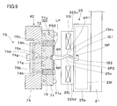
図9に示すように、チャック装置25の第1及び第2チャック部材325c,325dには、成形コマ部25m,25nがそれぞれ設けられている。これにより、第1及び第2チャック部材325c,325dでスプルー部SPを挟む際に、両成形コマ部25m,25nの内側面(転写面)IS1,IS2によってスプルー部SPの表面SP1,SP2に内側面IS1,IS2の形状を転写することができる。この場合、内側面IS1,IS2はうねるように湾曲しており、スプルー部SPに湾曲した部分を形成することができる。このような追加的な成形工程後は、スプルー部SPが冷却されて固化するので、両チャック部材325c,325dによるスプルー部SPの把持を確実なものとできる。これによって、製品部LPを切り取る処理工程に移行するときやその処理工程中において、成形品MPの取り扱いが容易になる。なお、成形コマ部25m,25nは、交換可能であってもよい。
〔第4実施形態〕
以下、本発明に係る熱可塑性樹脂製品の製造方法及び装置の第4実施形態について説明する。第4実施形態の製造方法等は、第1及び第3実施形態の製造方法等を変形したものであり、特に説明しない事項は、第1実施形態の製造方法等と同様である。
以下、本発明に係る熱可塑性樹脂製品の製造方法及び装置の第4実施形態について説明する。第4実施形態の製造方法等は、第1及び第3実施形態の製造方法等を変形したものであり、特に説明しない事項は、第1実施形態の製造方法等と同様である。
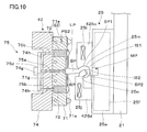
図10に示すように、チャック装置25の第1及び第2チャック部材425c,425dには、成形コマ部25m,25nがそれぞれ設けられている。これにより、第1及び第2チャック部材425c,425dでスプルー部SPを挟む際に、両成形コマ部25m,25nの内側面(転写面)IS1,IS2によってスプルー部SPの表面SP1,SP2に内側面IS1,IS2の形状を転写することができる。この場合、内側面IS1,IS2は捻るように湾曲しており、スプルー部SPに鈎状の部分を形成することができる。このような追加的な成形工程後は、スプルー部SPが冷却されて固化するので、両チャック部材425c,425dによるスプルー部SPの把持を確実なものとできる。
この実施形態の場合、スプルー部SPが鈎状となるので、成形品MPを吊るすことができる。これにより、取り出し不良や処理工程のゲートカットの位置ズレなどの不良を低減できる。
以上、実施形態に即して熱可塑性樹脂製品の製造方法の製造方法等について説明したが、本発明は上記のものに限定されるものではなく、様々な変形が可能である。例えば、上記実施形態において、第1金型41及び第2金型42で構成される射出成形金型に設ける成形空間CVの形状は、様々な形状とすることができる。すなわち、転写凹部61e,71e等によって形成される成形空間CVの形状は、単なる例示であり、製品部LPは、レンズに限らず様々な光学素子とすることができ、光学素子以外であってもよい。
また、以上の実施形態では、チャック装置25によってスプルー部SPを把持してスプルー部SPの成形を行っているが、チャック装置25によってランナー部RPを把持してランナー部RPの成形を行ってから成形品MPの搬出を行うこともできる。
また、上記実施形態において、横型の製造装置100を用いたが、竪型の成形装置を用いてもよい。成形品MPは、重力に関係なく例えば冷却状態に起因して変形することもあり、チャック装置25による軟化したスプルー部SP等の成形による固化がスループット向上等の観点で意味を持つ。
また、上記実施形態において、成形品MPをエジェクターピン75a,75b等で突き出して第2金型42から離型したが、取出装置20によって離型してもよい。
また、上記実施形態において、成形品MPが第2金型42に残ったが、第1金型41に残ってもよい。この場合、取出装置20によって、第1金型41に残った成形品MPのランナー部RP、スプルー部SP等の非製品部分に対して成形を行い成形品MPを取り出す。
Claims (10)
- 第1の金型と第2の金型とを備える金型装置に熱可塑性樹脂を供給することによって、製品部と、前記第1の金型と前記第2の金型との型閉じによって形成される熱可塑性樹脂用の流路に対応して前記製品部から延びる非製品部とを含む成形品を成形する熱可塑性樹脂製品の製造方法であって、
前記製品部がガラス転移点より低い温度状態であり、かつ、前記非製品部が前記ガラス転移点以上に高い温度状態であるときに、前記金型装置からの前記成形品の取り出しを開始する熱可塑性樹脂製品の製造方法。 - 前記非製品部は、前記成形品を取り出す際に成形される、請求項1に記載の熱可塑性樹脂製品の製造方法。
- 前記非製品部が前記ガラス転移点に50℃加算した温度以下であるときに、前記成形品を取り出す、請求項1に記載の熱可塑性樹脂製品の製造方法。
- 前記成形品を取り出すための取出装置に冷却装置を組み込んで、当該冷却装置によって前記成形品の前記非製品部を冷却する、請求項1に記載の熱可塑性樹脂製品の製造方法。
- 前記成形品を取り出すための取出装置にコマ部を設けて、前記成形品の前記非製品部のうちスプルー部に前記コマ部の形状を転写する、請求項1に記載の熱可塑性樹脂製品の製造方法。
- 前記成形品の前記非製品部の最大厚みは、前記製品部の最大厚みよりも大きい、請求項1に記載の熱可塑性樹脂製品の製造方法。
- 前記金型装置は、前記ガラス転移点より低い温度に設定され、前記ガラス転移点以上の高い温度の熱可塑性樹脂を前記金型装置の前記流路に供給する、請求項1に記載の熱可塑性樹脂製品の製造方法。
- 前記金型装置の型開き後に前記第1及び第2の金型うち一方に残った前記成形品をエジェクトした直後のタイミングで、前記成形品を取り出すための取出装置によって前記非製品部を把持して成形を行う、請求項7に記載の熱可塑性樹脂製品の製造方法。
- 前記金型装置の型開き後に前記第1及び第2の金型うち一方に残った前記成形品の前記非製品部を加熱することによって前記ガラス転移点以上の高い温度まで加熱したタイミングで、前記成形品を取り出すための取出装置によって前記非製品部を把持して成形を行う、請求項7に記載の熱可塑性樹脂製品の製造方法。
- 第1の金型と第2の金型とを有する金型装置と、前記金型装置に熱可塑性樹脂を供給する供給装置と、前記金型装置によって成形された成形品を取り出す取出装置とを備える熱可塑性樹脂製品の製造装置であって、
前記成形品は、製品部と、前記第1の金型と前記第2の金型との型閉じによって形成される熱可塑性樹脂用の流路に対応して前記製品部から延びる非製品部とを含み、
前記取出装置は、前記製品部がガラス転移点より低い温度状態であり、かつ、前記非製品部が前記ガラス転移点以上に高い温度状態であるときに、前記成形品の取り出しを開始する熱可塑性樹脂製品の製造装置。
Applications Claiming Priority (2)
| Application Number | Priority Date | Filing Date | Title |
|---|---|---|---|
| JP2012079002 | 2012-03-30 | ||
| JP2012-079002 | 2012-03-30 |
Publications (1)
| Publication Number | Publication Date |
|---|---|
| WO2013146871A1 true WO2013146871A1 (ja) | 2013-10-03 |
Family
ID=49260120
Family Applications (1)
| Application Number | Title | Priority Date | Filing Date |
|---|---|---|---|
| PCT/JP2013/058981 WO2013146871A1 (ja) | 2012-03-30 | 2013-03-27 | 熱可塑性樹脂製品の製造方法及び装置 |
Country Status (2)
| Country | Link |
|---|---|
| JP (1) | JPWO2013146871A1 (ja) |
| WO (1) | WO2013146871A1 (ja) |
Cited By (1)
| Publication number | Priority date | Publication date | Assignee | Title |
|---|---|---|---|---|
| CN113211745A (zh) * | 2021-04-24 | 2021-08-06 | 杨帅 | 一种快速成型的注塑模具 |
Citations (3)
| Publication number | Priority date | Publication date | Assignee | Title |
|---|---|---|---|---|
| JP2002103405A (ja) * | 2000-10-04 | 2002-04-09 | Olympus Optical Co Ltd | 光学素子の成形方法及び成形金型 |
| JP2010089293A (ja) * | 2008-10-03 | 2010-04-22 | Konica Minolta Opto Inc | 成形方法 |
| JP2010201842A (ja) * | 2009-03-05 | 2010-09-16 | Panasonic Electric Works Co Ltd | 照明デバイス用カバーおよびその製造方法 |
-
2013
- 2013-03-27 WO PCT/JP2013/058981 patent/WO2013146871A1/ja active Application Filing
- 2013-03-27 JP JP2014507952A patent/JPWO2013146871A1/ja not_active Withdrawn
Patent Citations (3)
| Publication number | Priority date | Publication date | Assignee | Title |
|---|---|---|---|---|
| JP2002103405A (ja) * | 2000-10-04 | 2002-04-09 | Olympus Optical Co Ltd | 光学素子の成形方法及び成形金型 |
| JP2010089293A (ja) * | 2008-10-03 | 2010-04-22 | Konica Minolta Opto Inc | 成形方法 |
| JP2010201842A (ja) * | 2009-03-05 | 2010-09-16 | Panasonic Electric Works Co Ltd | 照明デバイス用カバーおよびその製造方法 |
Cited By (1)
| Publication number | Priority date | Publication date | Assignee | Title |
|---|---|---|---|---|
| CN113211745A (zh) * | 2021-04-24 | 2021-08-06 | 杨帅 | 一种快速成型的注塑模具 |
Also Published As
| Publication number | Publication date |
|---|---|
| JPWO2013146871A1 (ja) | 2015-12-14 |
Similar Documents
| Publication | Publication Date | Title |
|---|---|---|
| WO2009122862A1 (ja) | 光学素子の製造方法、光学素子成形金型、及び光学素子 | |
| JP5259461B2 (ja) | 金属ガラスと高分子材料との一体成形品の成形方法、及び、一体成形品用成形装置 | |
| WO2012043224A1 (ja) | 光学素子の製造方法 | |
| WO2010061728A1 (ja) | 光学素子の製造方法及び成形金型 | |
| WO2011037038A1 (ja) | 成形金型及び成形方法 | |
| WO2013146871A1 (ja) | 熱可塑性樹脂製品の製造方法及び装置 | |
| JP2009137162A (ja) | 2色成形方法及び2色成形用金型 | |
| JP2010082838A (ja) | レンズ製造方法 | |
| JP2008230005A (ja) | プラスチックレンズ成形方法およびレンズプリフォーム | |
| WO2005084910A1 (ja) | ディスク成形用金型、調整部材及びディスク基板の成形方法 | |
| JP2014061601A (ja) | 光学素子の製造方法 | |
| JP5298749B2 (ja) | 成形方法 | |
| JP2010083025A (ja) | 光学素子の製造方法及び光学素子成形金型 | |
| JP2012158088A (ja) | 光学素子の製造方法及び成形金型 | |
| JP2014061597A (ja) | 成形装置及び光学素子の製造方法 | |
| JP2009241297A (ja) | 光学素子の製造方法、光学素子成形金型、及び光学素子 | |
| JP2008087407A (ja) | 射出成形方法 | |
| JP2005343152A (ja) | スプル保温・加熱機能を備えた射出成型金型 | |
| WO2011040180A1 (ja) | 成形金型 | |
| JP2013159015A (ja) | 成形用金型及び光学素子の製造方法 | |
| WO2013047289A1 (ja) | 光学素子の製造方法、及び、成形金型 | |
| JP2008284704A (ja) | 成形型および光学素子の製造方法 | |
| JP2013169691A (ja) | 成形装置及び光学素子の製造方法 | |
| WO2013147106A1 (ja) | 成形金型及びレンズの製造方法 | |
| JP2013078869A (ja) | 成形装置 |
Legal Events
| Date | Code | Title | Description |
|---|---|---|---|
| 121 | Ep: the epo has been informed by wipo that ep was designated in this application |
Ref document number: 13769440 Country of ref document: EP Kind code of ref document: A1 |
|
| ENP | Entry into the national phase |
Ref document number: 2014507952 Country of ref document: JP Kind code of ref document: A |
|
| 122 | Ep: pct application non-entry in european phase |
Ref document number: 13769440 Country of ref document: EP Kind code of ref document: A1 |
|
| NENP | Non-entry into the national phase |
Ref country code: DE |