WO2013146871A1 - Procédé et dispositif de fabrication de produit en résine thermoplastique - Google Patents
Procédé et dispositif de fabrication de produit en résine thermoplastique Download PDFInfo
- Publication number
- WO2013146871A1 WO2013146871A1 PCT/JP2013/058981 JP2013058981W WO2013146871A1 WO 2013146871 A1 WO2013146871 A1 WO 2013146871A1 JP 2013058981 W JP2013058981 W JP 2013058981W WO 2013146871 A1 WO2013146871 A1 WO 2013146871A1
- Authority
- WO
- WIPO (PCT)
- Prior art keywords
- product
- mold
- molded product
- thermoplastic resin
- glass transition
- Prior art date
Links
Images


Classifications
-
- B—PERFORMING OPERATIONS; TRANSPORTING
- B29—WORKING OF PLASTICS; WORKING OF SUBSTANCES IN A PLASTIC STATE IN GENERAL
- B29C—SHAPING OR JOINING OF PLASTICS; SHAPING OF MATERIAL IN A PLASTIC STATE, NOT OTHERWISE PROVIDED FOR; AFTER-TREATMENT OF THE SHAPED PRODUCTS, e.g. REPAIRING
- B29C45/00—Injection moulding, i.e. forcing the required volume of moulding material through a nozzle into a closed mould; Apparatus therefor
- B29C45/17—Component parts, details or accessories; Auxiliary operations
- B29C45/40—Removing or ejecting moulded articles
- B29C45/42—Removing or ejecting moulded articles using means movable from outside the mould between mould parts, e.g. robots
- B29C45/4225—Take-off members or carriers for the moulded articles, e.g. grippers
-
- B—PERFORMING OPERATIONS; TRANSPORTING
- B29—WORKING OF PLASTICS; WORKING OF SUBSTANCES IN A PLASTIC STATE IN GENERAL
- B29C—SHAPING OR JOINING OF PLASTICS; SHAPING OF MATERIAL IN A PLASTIC STATE, NOT OTHERWISE PROVIDED FOR; AFTER-TREATMENT OF THE SHAPED PRODUCTS, e.g. REPAIRING
- B29C45/00—Injection moulding, i.e. forcing the required volume of moulding material through a nozzle into a closed mould; Apparatus therefor
- B29C45/17—Component parts, details or accessories; Auxiliary operations
- B29C45/72—Heating or cooling
- B29C45/7207—Heating or cooling of the moulded articles
-
- B—PERFORMING OPERATIONS; TRANSPORTING
- B29—WORKING OF PLASTICS; WORKING OF SUBSTANCES IN A PLASTIC STATE IN GENERAL
- B29C—SHAPING OR JOINING OF PLASTICS; SHAPING OF MATERIAL IN A PLASTIC STATE, NOT OTHERWISE PROVIDED FOR; AFTER-TREATMENT OF THE SHAPED PRODUCTS, e.g. REPAIRING
- B29C45/00—Injection moulding, i.e. forcing the required volume of moulding material through a nozzle into a closed mould; Apparatus therefor
- B29C45/17—Component parts, details or accessories; Auxiliary operations
- B29C45/76—Measuring, controlling or regulating
- B29C45/7626—Measuring, controlling or regulating the ejection or removal of moulded articles
-
- B—PERFORMING OPERATIONS; TRANSPORTING
- B29—WORKING OF PLASTICS; WORKING OF SUBSTANCES IN A PLASTIC STATE IN GENERAL
- B29C—SHAPING OR JOINING OF PLASTICS; SHAPING OF MATERIAL IN A PLASTIC STATE, NOT OTHERWISE PROVIDED FOR; AFTER-TREATMENT OF THE SHAPED PRODUCTS, e.g. REPAIRING
- B29C45/00—Injection moulding, i.e. forcing the required volume of moulding material through a nozzle into a closed mould; Apparatus therefor
- B29C45/17—Component parts, details or accessories; Auxiliary operations
- B29C45/76—Measuring, controlling or regulating
- B29C45/78—Measuring, controlling or regulating of temperature
-
- B—PERFORMING OPERATIONS; TRANSPORTING
- B29—WORKING OF PLASTICS; WORKING OF SUBSTANCES IN A PLASTIC STATE IN GENERAL
- B29C—SHAPING OR JOINING OF PLASTICS; SHAPING OF MATERIAL IN A PLASTIC STATE, NOT OTHERWISE PROVIDED FOR; AFTER-TREATMENT OF THE SHAPED PRODUCTS, e.g. REPAIRING
- B29C45/00—Injection moulding, i.e. forcing the required volume of moulding material through a nozzle into a closed mould; Apparatus therefor
- B29C45/17—Component parts, details or accessories; Auxiliary operations
- B29C45/76—Measuring, controlling or regulating
- B29C45/7626—Measuring, controlling or regulating the ejection or removal of moulded articles
- B29C2045/7633—Take out or gripping means
-
- B—PERFORMING OPERATIONS; TRANSPORTING
- B29—WORKING OF PLASTICS; WORKING OF SUBSTANCES IN A PLASTIC STATE IN GENERAL
- B29L—INDEXING SCHEME ASSOCIATED WITH SUBCLASS B29C, RELATING TO PARTICULAR ARTICLES
- B29L2011/00—Optical elements, e.g. lenses, prisms
- B29L2011/0016—Lenses
Definitions
- the present invention relates to a method and an apparatus for producing a thermoplastic resin product obtained by molding an optical element or other thermoplastic resin product.
- the molded product after removal may be subjected to gate cutting and other processing steps.
- the shape of the sprue of the molded product is often a conical shape that is easy to release from the mold apparatus, and there is a problem that it is difficult to grip the sprue portion stably if it is not gripped with a strong force. This leads to defects such as an extraction failure in the extraction process and a shift of the gate cut position in the processing process.
- the molten resin is cooled and solidified, but if it is sufficiently cooled, the molded product is distorted due to the difference in shrinkage between the mold member and the resin.
- the resin temperature of the molded product becomes equal to or higher than the glass transition point, and the mold opening process is started while the molded product remains soft.
- the shape of the molded product is easily deformed, in particular, the sprue part and the runner part near the molten resin inlet are easily deformed, and in an extreme case, the sprue part is torn off. For example, if the sprue portion that should be gripped by the chuck portion in the take-out process is deformed, the take-out becomes difficult and a take-out failure occurs.
- Patent Document 1 proposes a method for forcibly cooling the sprue portion.
- the structure is such that the heat of the sprue part is taken by flowing a cooling medium around the sprue part.
- the cooling speed is increased with such a structure, the heat is taken away by the sprue part until the molten resin reaches the product part, so the molten resin flows into the product space corresponding to the product part of the mold.
- This causes problems such as sink marks and welds that deteriorate the transferability of the product shape.
- the present invention makes it possible to stably take out a molded product, and to ensure that the sprue portion is sufficiently solidified while avoiding the occurrence of shrinkage distortion in the molded product, thereby making it possible to reliably take out the molded product. It is an object of the present invention to provide a method and an apparatus for producing a thermoplastic resin product that can ensure transferability and hardly cause internal distortion or the like in a molded product.
- a method for producing a thermoplastic resin product comprises supplying a thermoplastic resin to a mold apparatus including a first mold and a second mold, thereby producing a product part, A thermoplastic resin product for molding a molded product including a non-product part extending from the product part corresponding to a flow path for the thermoplastic resin formed by closing the mold between the first mold and the second mold
- the product part is in a temperature state lower than the glass transition point and the non-product part is in a temperature state higher than the glass transition point
- the removal of the molded product from the mold apparatus is started.
- the molded product means all parts obtained by solidifying thermoplastic resin such as sprue parts, runner parts, product parts and the like.
- the product part is a part to be a final product (for example, an optical element) and means a part on the tip side of the gate part.
- the non-product part when the non-product part is at a temperature higher than the glass transition point, the removal of the molded product is started, so not only the cycle time of the molding can be shortened by shortening the cooling process. Since the product part is at a temperature lower than the glass transition point at the start of taking out the molded product, deformation of the product part and occurrence of internal distortion can be prevented.
- the non-product part is molded when the molded product is taken out in the above manufacturing method, the non-product part is accurately and reliably taken out by the non-product part. It is possible to prevent the portion from being deformed or broken into an unintended shape.
- the non-product part is in a temperature state higher than the glass transition point in the take-out process, as a result, it is possible to prevent the product part from being excessively cooled in the mold and causing shrinkage distortion, and to the product space. This facilitates the inflow of the resin and secures good transferability with respect to the product shape.
- the molded product is taken out when the non-product portion is below the temperature obtained by adding 50 ° C. to the glass transition point.
- the temperature of the non-product part when taking out the molded product is more preferably set to a temperature obtained by adding 20 ° C. to the glass transition point.
- the temperature of the non-product part when taking out the molded product is more preferably not more than the temperature obtained by adding 10 ° C. to the glass transition point.
- a cooling device is incorporated into a take-out device for taking out a molded product, and a non-product part of the molded product is cooled by the cooling device.
- the shape of the non-product part can be quickly stabilized by cooling the non-product part.
- a top part (shape transfer part) is provided in a take-out device for taking out a molded product, and the shape of the top part is transferred to the sprue part of the non-product part of the molded product.
- the shape of the top portion is transferred to the sprue portion, and the molded product can be quickly taken out.
- the maximum thickness of the non-product part of the molded product is larger than the maximum thickness of the product part. In this case, it becomes easier to create conditions such that the product part is in a temperature state lower than the glass transition point and the non-product part is in a temperature state higher than the glass transition point, and it is easy to ensure and adjust the take-out timing of the molded product. It becomes.
- the mold apparatus is set to a temperature lower than the glass transition point, and a thermoplastic resin having a temperature higher than the glass transition point is supplied to the flow path of the mold apparatus.
- the resin flowing into the product space is cooled to a temperature lower than the glass transition point, and the resin in the non-product portion is easily held at a temperature higher than the glass transition point.
- the non-product is removed by the take-out device for taking out the molded product at a timing immediately after ejecting the molded product remaining in one of the first and second molds after the mold device is opened. Hold the part and mold. In this case, the possibility of distortion and deformation occurring in the product part can be reduced, and the non-product part is suitable for molding the non-product part at a relatively high temperature.
- the non-product part of the molded product remaining in one of the first and second molds is heated to a temperature higher than the glass transition point.
- the non-product part is gripped by the take-out device for taking out the molded product and molding is performed.
- the non-product part can be forced to a temperature suitable for molding, and the non-product part can be easily molded.
- an apparatus for manufacturing a thermoplastic resin product includes a mold apparatus having a first mold and a second mold, and a supply for supplying thermoplastic resin to the mold apparatus.
- An apparatus for manufacturing a thermoplastic resin product including an apparatus and a take-out device for taking out a molded product molded by a mold device, wherein the molded product includes a product portion, a first mold, and a second mold.
- the take-out device is in a temperature state where the product part is lower than the glass transition point, and the non-product When the part is at a temperature higher than the glass transition point, the removal of the molded product is started.
- thermoplastic resin product manufacturing apparatus when the take-out device is in a temperature state in which the product part is lower than the glass transition point and the non-product part is in a temperature state higher than the glass transition point, the molded product Therefore, the deformation of the product part and the occurrence of internal distortion can be prevented.
- a non-product part can also be shape
- the non-product part is in a temperature state higher than the glass transition point in the take-out process, as a result, it is possible to prevent the product part from being excessively cooled in the mold and causing shrinkage distortion, and to the product space. This facilitates the inflow of the resin and secures good transferability with respect to the product shape.
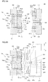
- FIG. 2A is a side cross-sectional view for explaining a mold open state before molding of the first and second molds incorporated in the molding apparatus of FIG. 1, and FIG. 2B is a mold of the first and second molds. It is a sectional side view explaining a closed state.
- FIG. 3A is a side cross-sectional view for explaining the mold opening state after the first and second molds are molded, and FIG. 3B is a side cross-sectional view for explaining the protrusion of the molded product.
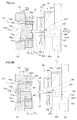
- FIG. 4A is a side cross-sectional view for explaining the molded product chuck by the take-out device, and FIG.
- FIG. 4B is a side cross-sectional view for explaining the take-out of the molded product by the take-out device.
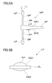
- FIG. 5A is a side sectional view of a molded product molded by the first and second molds
- FIG. 5B is a side view of the optical element.
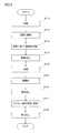
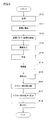
- It is a flowchart explaining the manufacturing method using the shaping
- It is a conceptual diagram explaining the principal part of the shaping
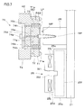
- an apparatus 100 for manufacturing a thermoplastic resin product is an injection molding machine 10 that is a main body part that performs injection molding to produce a molded product MP, and for taking out the molded product MP from the injection molding machine 10.
- a take-out device 20 that is an attached portion and a control device 30 that comprehensively controls the operation of each part of the manufacturing apparatus 100 are provided.
- the injection molding machine 10 is a horizontal molding machine and includes a molding die 40, a fixed platen 11, a movable platen 12, a mold clamping plate 13, an opening / closing drive device 15, and an injection device 16.
- the injection molding machine 10 clamps both molds 41 and 42 by sandwiching a first mold 41 and a second mold 42 constituting the molding mold 40 between the fixed platen 11 and the movable platen 12. This enables molding.
- the fixed platen 11 is fixed to the approximate center of the support frame 14 so as to face the movable platen 12, and supports the take-out device 20 on the top thereof.
- the inner side 11a of the heel fixed platen 11 faces the inner side 12a of the movable platen 12, and supports the first mold 41 in a detachable manner.
- the fixed platen 11 is formed with an opening 11b through which a later-described resin supply nozzle 16d is passed. Note that the fixed platen 11 is fixed to the mold clamping plate 13 via a tie bar so that it can withstand the pressure of mold clamping during molding.
- the movable platen 12 is supported by a linear guide 15a, which will be described later, so as to be movable back and forth with respect to the fixed platen 11.
- the inner side 12a of the movable platen 12 faces the inner side 11a of the fixed platen 11, and supports the second mold 42 in a detachable manner.
- an ejector driving unit 45 is incorporated in the movable platen 12. The ejector driving unit 45 is for extruding the molded product MP in the second mold 42 toward the first mold 41 in order to release the molded product MP.
- the mold clamping machine 13 is fixed to the end of the support frame 14.
- the mold clamping machine 13 supports the movable board 12 from the back via the power transmission part 15d of the opening / closing drive device 15 at the time of mold clamping.
- the opening / closing drive device 15 includes a linear guide 15a, a power transmission unit 15d, and an actuator 15e.
- the linear guide 15 a supports the movable platen 12 and enables the movable platen 12 to smoothly reciprocate with respect to the advancing and retreating direction with respect to the fixed platen 11.
- the power transmission unit 15 d expands and contracts in response to the driving force from the actuator 15 e that operates under the control of the control device 30.
- the movable platen 12 moves forward and backward freely with respect to the mold clamping plate 13, close to or away from the mold clamping plate 13.
- the fixed platen 11 and the movable platen 12 can be brought close to or separated from each other, and the first die 41 and the second die 42 can be closed (including clamping) or opened. it can.
- the injection device 16 includes a cylinder 16a, a raw material storage unit 16b, a screw drive unit 16c, and the like.
- the injection device 16 operates at an appropriate timing under the control of the control device 30, and is a nozzle for injecting a thermoplastic resin (molten resin) that is melted in the cylinder 16a and temperature-controlled by the heater 16h. Inject from 16d.
- the injection device 16 brings the nozzle 16d into contact with a sprue bush 65 (see FIG. 2B and the like) to be described later through the opening 11b of the stationary platen 11. .
- the molten resin held above the glass transition point can be supplied to the flow path space FC (see FIG. 2B and the like) described later at a desired timing and pressure.
- the injection device 16 is a supply device that supplies a thermoplastic resin to a molding die (molding device) 40 having a first die 41 and a second die 42.
- a mold temperature controller 46 attached to the injection molding machine 10 circulates a temperature-controlled heat medium in both molds 41 and 42. Thereby, at the time of shaping
- the take-out device 20 includes an arm 21 that can hold the molded product MP and a three-dimensional drive device 22 that moves the arm 21 three-dimensionally.
- the take-out device 20 operates at an appropriate timing under the control of the control device 30, and remains in the second die 42 after the first die 41 and the second die 42 are separated and opened. It has the role of gripping the molded product MP and carrying it out.
- a chuck device 25 is provided at the lower end of the arm 21 in the take-out device 20 and holds the sprue portion SP and the like of the molded product MP.
- the control device 30 includes an opening / closing control unit 31, an injection device control unit 32, an ejector control unit 33, and a take-out device control unit 34.
- the opening / closing control unit 31 enables the molds 41 and 42 to be closed, clamped, opened, and the like by operating the actuator 15e.
- the injection device control unit 32 injects resin at a desired temperature and pressure into a molding space CV (see FIG. 2B) formed between both molds 41 and 42 by operating the screw driving unit 16c, the heater 16h, and the like.
- the ejector control unit 33 operates the ejector driving unit 45 to push out the molded product MP remaining in the second mold 42 when the mold is opened from the second mold 42 to release the mold.
- the take-out device control unit 34 operates the take-out device 20 to grip the molded product MP remaining in the second mold 42 after mold opening and release, and to perform additional molding on the molded product MP.
- the molded product MP after additional molding is carried out of the injection molding machine 10.
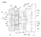
- dies 40 can be reciprocated to AB direction. As shown in FIG. 2B, the second mold 42 is moved toward the first mold 41, and both molds 41, 42 are mold-matched with the mold-matching surfaces PS1, PS2 and clamped. A molding space CV for molding the part LP (lens) and a channel space FC that is a channel for supplying resin to the molding space CV are formed.
- the first mold 41 includes a mold plate 61 disposed on the inner side, that is, the mold mating surface PS1 side, a plurality of core molds 62 embedded in the mold plate 61, and an attachment disposed on the outer side, that is, the fixed platen 11 side in FIG. Plate 64.
- a sprue bushing 65 is provided in association with the first mold 41.
- the nozzle 16d provided at the tip of the cylinder 16a is brought into contact with the inlet of the sprue bush 65 on the fixed platen 11 side (see FIG. 1) when the molten resin is supplied from the injection device 16 into the molding die 40.
- the template 61 of the first mold 41 is a metal plate-like member, and includes a plurality of core holes 61a into which the plurality of core dies 62 are inserted, and a sprue hole 66 for allowing resin to flow into the molding space CV.
- the core holes 61a are provided at, for example, four locations on the circumference centered on the sprue hole 66.
- the sprue hole 66 has a conical inner surface and extends substantially parallel to the AB direction which is the mold opening / closing direction and penetrates the first mold 41.
- thermometer 52 for heating, a heater for heating (not shown), and the like are incorporated.
- the core mold 62 is a cylindrical member extending in the AB direction, and a transfer recess 61e is formed on the tip surface thereof.
- the transfer recess 61e has a mirror-like first transfer surface S1, and when the product portion LP of the molded product MP is a component of an imaging lens or an objective lens, the transfer recess 61e has a shape corresponding to the optical surface of these objects. Processed.
- the first transfer surface S1 may be a surface provided with a fine structure.
- the mounting plate 64 is a metal plate-like member, and supports the template 61 from behind. That is, the mounting plate 64 supports the template 61 from the opposite side (back side) of the die-matching surface PS1. Although illustration is omitted, the mounting plate 64 has a plurality of fastening members for fixing the mounting plate 64 itself to the fixed platen 11.
- the second mold 42 includes a mold plate 71 disposed on the inner side, that is, the mold mating surface PS2 side, a plurality of core molds 72 embedded in the mold plate 71, and an attachment disposed on the outer side, that is, the movable platen 12 side in FIG.
- a plate 74 and an ejector member 75 formed to be embedded in the mounting plate 74 are provided.
- the template 71 of the second mold 42 is a metal plate-like member, a plurality of core holes 71a into which the plurality of core dies 72 are inserted, a cold slug 71b facing the tip of the sprue hole 66, A runner recess 71f branched from the cold slug 71b and extending in a plurality of directions.
- a plurality of core holes 71 a are provided to face the core holes 61 a provided in the template 61 of the first mold 41.
- the runner recesses 71f extend radially from the cold slugs 71b toward the transfer recesses 71e.
- the runner recess 71f forms a runner RB in the flow path space FC that communicates with the molding space CV when the first and second molds 41 and 42 are closed (see FIG. 2B).
- the core mold 72 is a cylindrical member extending in the AB direction, and a transfer recess 71e is formed on the tip surface thereof.
- the transfer recess 71e formed in the core mold 72 and the transfer formed in the core mold 62 embedded in the mold plate 61 of the first mold 41.
- a molding space CV is formed between the recesses 61e.
- the transfer recess 71e has a mirror-like second transfer surface S2, and when the product portion LP of the molded product MP is a component of the imaging lens or objective lens, the transfer recess 71e has a shape corresponding to the optical surface of these objects.
- the second transfer surface S2 may be a surface provided with a fine structure.
- a pin hole 71g through which an ejector pin 75a constituting the ejector member 75 is passed is also formed in the template 71.
- thermometer 52 for heating, a heater for heating (not shown), and the like are incorporated.
- the mounting plate 74 is a metal plate-like member, and supports the template 71 from behind.
- the mounting plate 74 includes pin holes 74g and 74h through which the ejector pins 75a and 75b constituting the ejector member 75 are passed. Although illustration is omitted, the attachment plate 74 has a plurality of fastening members for fixing the attachment plate 74 itself to the movable platen 12.
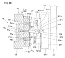
- the ejector member 75 is a mechanical mechanism having ejector pins 75a and 75b and an ejector plate 75d, and operates by being driven by the ejector driving unit 45 of FIG.
- the ejector pins 75a and 75b are connected to the ejector plate 75d, and can be moved forward and backward collectively in the pin holes 71g of the template 71 and the pin holes 74g and 74h of the mounting plate 74.
- the ejector pins 75a and 75b move forward.
- the central ejector pin 75a protrudes from the bottom of the cold slug 71b of the template 71, and the peripheral ejector pin 75b pushes the core mold 72. Press to project from the mold matching surface PS2.
- the ejector member 75 is set in the retracted state, the ejector pins 75a and 75b are retracted, and the central ejector pin 75a is retracted into the bottom of the cold slug 71b of the template 71, and the peripheral ejector pins 75b are similarly.
- the core mold 72 is allowed to retract by retracting.
- the core mold 72 has a structure with an unillustrated spring or the like attached thereto, and when it receives no urging force to advance from the ejector pin 75b, it retracts and is housed in the core hole 71a.
- die 42 fit the positioning fitting part 41x provided in the 1st metal mold
- the chuck device 25 includes a support base portion 25a and first and second chuck members 25c and 25d.
- the support base 25a includes a chuck driving unit 25f that causes the pair of chuck members 25c and 25d to perform a clamping operation. Both chuck members 25c and 25d can be displaced in the vertical CD direction by being driven by a chuck drive section 25f.
- Both chuck members 25c and 25d are driven by the chuck drive unit 25f and operate in synchronization. Both chuck members 25c and 25d can grip the sprue portion SP of the molded product MP by approaching each other, and can release the grip of the sprue portion SP by separating from each other synchronously. Inner side surfaces IS1 and IS2 of both chuck members 25c and 25d are formed surfaces, and shape transfer, that is, molding is performed on the surfaces SP1 and SP2 of the sprue portion SP that is still softened.
- a cooling device 25j is built in each chuck member 25c, 25d, and cools the chuck members 25c, 25d to a predetermined temperature lower than the glass transition point.
- the cooling device 25j can be composed of, for example, a Peltier element.
- the cooling device 25j can be replaced with a heat sink structure, a heat pipe, a cold water pipe, or the like, or can be replaced with a fan or other air cooling device.
- a plurality of runner portions RP extends around the sprue portion SP, and a product portion LP is formed on the extension of the runner portion RP.
- the runner part RP and the sprue part SP excluding the product part LP in the molded product MP are non-product parts.
- Each product part LP is obtained by cutting the gate GP at the boundary between the runner part RP and the product part LP.
- the maximum thickness t1 of the product portion LP in the optical axis direction is smaller than the maximum thickness t2 of the sprue portion SP in the diameter direction. For this reason, when the molded product MP is manufactured, the product portion LP is cooled earlier than the sprue portion SP, and the product portion LP can be easily cooled to a temperature lower than that of the sprue portion SP. Specifically, for example, the product portion LP is easily brought into a temperature state lower than the glass transition point of the molten resin, and the sprue portion SP is easily brought into a temperature state equal to or higher than the glass transition point of the molten resin.
- the product part LP has an optical function part OP and a flange part FL.
- the optical function portion OP is formed by the first optical surface OS1 formed by, for example, the transfer recess 61e among the transfer recesses 61e, 71e provided in the molding die 40 of FIG. And a second optical surface OS2.
- the product part LP is an imaging lens mounted on, for example, an imaging device (including those mounted on a portable terminal such as a notebook PC).
- the product portion LP can also be an objective lens for a thick-type optical pickup device having a large protrusion on the first optical surface OS1 side.
- the product unit LP enables reading or writing of optical information corresponding to a BD (Blu-ray (registered trademark) Disc) having a wavelength of 405 nm and a numerical aperture (NA) of 0.85, for example.
- the molded product MP including the product part LP is formed of an optical resin.
- the optical resin for example, COC (cycloolefin copolymer), PMMA (polymenthyl methacrylate) and the like are used.
- the mold temperature controller 46 heats both molds 41 and 42 to a temperature suitable for molding (step S10).
- the temperature of the mold surface forming the molding space CV in both the molds 41 and 42 and the temperature in the vicinity thereof are, for example, 20 ° C. lower than the glass transition point of the molten resin supplied from the injection device 16. In this state, the temperature is kept at a temperature lower than the glass transition point.
- the opening / closing drive device 15 is operated to advance the movable platen 12 to start mold closing (step S11).
- the movable platen 12 moves to the fixed platen 11 side to the die contact position where the first die 41 on the fixed side and the second die 42 on the movable side come into contact with each other.
- the mold closing is completed.
- mold clamping is performed to clamp the first mold 41 and the second mold 42 with necessary pressure (step S12).
- the injection device 16 is operated to bring the nozzle 16d into contact with the sprue bushing 65 of the first mold 41 and to inject the molten resin into the molding space CV with a necessary pressure.
- the temperature of the molten resin supplied from the injection device 16 is set to a temperature equal to or higher than the glass transition point, for example, 100 ° C. to 150 ° C. higher than the glass transition point.
- the injection molding machine 10 After the molding space CV is filled with resin, the injection molding machine 10 maintains the resin pressure in the molding space CV. At this time, the mold temperature controller 46 appropriately heats the molding space CV and the flow path space FC (see FIG. 2B) through which resin flows into the molding space CV, and the molten resin supplied from the injection device 16. Is moderately cooled, and moderate decooling of the resin in the molding space CV can be achieved. After the molten resin is introduced into the molding space CV, the molten resin in the molding space CV is gradually cooled by heat dissipation, so that the temperature of the resin in the molding space CV, that is, the product part LP is lower than the glass transition point. And wait for the molding to be completed (step S14).
- the temperature of the product part LP becomes a temperature lower than the glass transition point, it is considered that the molding is completed, and the temperature of the resin in the sprue hole 66, that is, the sprue part SP is lower than the glass transition point. I do not wait for that. That is, it does not wait until the entire molded product MP reaches a temperature lower than the glass transition point, but the molding is completed when the sprue portion SP is at a temperature equal to or higher than the glass transition point as will be described later.
- the opening / closing drive device 15 is operated to perform mold opening for retracting the movable platen 12 (step S15).
- the second mold 42 is retracted, and the first mold 41 and the second mold 42 are separated.
- the molded product MP that is, the product part LP, the runner part RP, and the like are released from the first mold 41 while being held by the second mold 42.
- step S16 the ejector driving unit 45 is operated, and the molded product MP including the product part LP is ejected by the advancement of the ejector pins 75a and 75b (step S16).
- the runner portion RP and the like of the molded product MP are pushed out to the first mold 41 side and released from the second mold 42.
- the take-out device 20 is operated to cause the chuck device 25 to perform an operation of gripping the molded product MP locked to the second mold 42.
- the removal of the molded product MP is started by the operation of causing the chuck device 25 to grip the molded product MP.
- the sprue portion SP of the molded product MP is at a temperature higher than the glass transition point, as shown in FIG. 4A, the surface of the sprue portion SP is formed by the inner side surfaces IS1, IS2 of both chuck members 25c, 25d.
- the shapes of the inner side surfaces IS1, IS2 are transferred to the SP1, SP2, and additional or auxiliary molding is performed on the sprue portion SP (step S17).
- the sprue portion SP is solidified with molding.
- the temperature of the sprue portion SP when the sprue portion SP is sandwiched between the chuck members 25c and 25d that is, the temperature of the sprue portion SP during additional molding is equal to or higher than the glass transition point, and is added to the glass transition point by 50 ° C. It is assumed that the temperature is lower than
- the temperature of the sprue portion SP at the time of additional molding is more preferably not more than a temperature obtained by adding 20 ° C. to the glass transition point, and further preferably not more than a temperature obtained by adding 10 ° C. to the glass transition point.
- the take-out device 20 is operated to completely separate the molded product MP from the second mold 42, and the molded product MP is taken out between the first and second molds 41 and 42. To the outside (step S18).
- the product part LP is in a temperature state lower than the glass transition point, and the non-product part (including the sprue part SP and the runner part RP) is higher than the glass transition point. Since the removal of the molded product MP is started in the temperature state, it is possible not only to prevent the deformation of the product part LP and the occurrence of internal distortion, but also to shorten the molding cycle time by shortening the cooling process. Further, according to the manufacturing method and the like, since the molded product MP can be molded when the sprue part SP which is a non-product part is taken out, the molded product MP can be accurately taken out by the sprue part SP which is a non-product part.
- the sprue portion SP which is a non-product portion
- the sprue portion SP which is a non-product portion
- the product portion LP is excessively cooled in the mold and shrinkage distortion occurs. It is possible to prevent the resin from flowing into the molding space CV, which is the product space, and to ensure good transferability with respect to the product shape.
- the arm 21 of the take-out device 20 is provided with a heating device 28 adjacent to the chuck device 25.
- the eaves heater 28 incorporates an infrared heater, for example, but can also send hot air.
- the sprue portion SP of the molded product MP remaining in one of the first and second molds 41 and 42 after the mold 40 is opened is heated from the surroundings, so that the glass transition point is reached. It is above and can be set as the state below the temperature which added 50 degreeC to the glass transition point.
- FIG. 8 is a diagram for explaining the manufacturing method of the second embodiment.
- the sprue portion SP is heated using the heating device 28 provided in the take-out device 20 of FIG. (Step S26). Accordingly, the sprue portion SP can be softened, and the chuck members SP can be sandwiched between the first and second chuck members 25c and 25d in the subsequent additional or auxiliary molding process.
- the shape of the inner side surfaces IS1, IS2 can be transferred to the surfaces SP1, SP2 of the sprue portion SP by the inner side surfaces IS1, IS2 of 25d (step S17).
- the first and second chuck members 325c and 325d of the chuck device 25 are provided with molding pieces 25m and 25n, respectively.
- the inner surfaces (transfer surfaces) IS1 and IS2 of the molding piece portions 25m and 25n are brought into the surfaces SP1 and SP2 of the sprue portion SP.
- the shape of the side surfaces IS1, IS2 can be transferred.
- the inner side surfaces IS1, IS2 are curved so as to undulate, and a curved portion can be formed in the sprue portion SP.
- the sprue portion SP is cooled and solidified, so that the gripping of the sprue portion SP by both chuck members 325c and 325d can be ensured. This facilitates handling of the molded product MP when shifting to the processing step of cutting the product portion LP or during the processing step.
- the molding piece portions 25m and 25n may be exchangeable.
- the fourth embodiment of the method and apparatus for producing a thermoplastic resin product according to the present invention will be described below.
- the manufacturing method of the fourth embodiment is a modification of the manufacturing method of the first and third embodiments, and matters not specifically described are the same as those of the manufacturing method of the first embodiment.
- the first and second chuck members 425c and 425d of the chuck device 25 are provided with molding pieces 25m and 25n, respectively.
- the inner side surfaces (transfer surfaces) IS1 and IS2 of the molding piece portions 25m and 25n are brought into the surfaces SP1 and SP2 of the sprue portion SP.
- the shape of the side surfaces IS1, IS2 can be transferred.
- the inner side surfaces IS1, IS2 are curved so as to be twisted, and a hook-like portion can be formed in the sprue portion SP.
- the sprue portion SP is cooled and solidified, so that the gripping of the sprue portion SP by both the chuck members 425c and 425d can be ensured.
- the sprue portion SP since the sprue portion SP has a bowl shape, the molded product MP can be suspended. As a result, it is possible to reduce defects such as takeout defects and misalignment of gate cuts in processing steps.
- the manufacturing method etc. of the manufacturing method of a thermoplastic resin product were demonstrated according to embodiment, this invention is not limited to the above thing, A various deformation
- the shape of the molding space CV provided in the injection mold including the first mold 41 and the second mold 42 can be various shapes. That is, the shape of the molding space CV formed by the transfer recesses 61e, 71e, etc. is merely an example, and the product portion LP can be a variety of optical elements, not limited to lenses. Good.
- the sprue portion SP is formed by gripping the sprue portion SP by the chuck device 25, but after the runner portion RP is gripped by the chuck device 25 and the runner portion RP is formed. It is also possible to carry out the molded product MP.
- the horizontal manufacturing apparatus 100 is used, but a vertical molding apparatus may be used.
- the molded product MP may be deformed due to, for example, a cooling state regardless of gravity, and solidification by molding of the sprue portion SP or the like softened by the chuck device 25 is meaningful from the viewpoint of improving throughput or the like.
- the molded product MP is ejected by the ejector pins 75 a and 75 b and released from the second mold 42, but may be released by the take-out device 20.
- the molded product MP remains in the second mold 42, but may remain in the first mold 41.
- the take-out device 20 forms the non-product part such as the runner part RP and the sprue part SP of the molded product MP remaining in the first mold 41 and takes out the molded product MP.
Landscapes
- Engineering & Computer Science (AREA)
- Manufacturing & Machinery (AREA)
- Mechanical Engineering (AREA)
- Robotics (AREA)
- Moulds For Moulding Plastics Or The Like (AREA)
Abstract
La présente invention porte sur un procédé et un dispositif pour fabriquer un produit en résine thermoplastique exceptionnel à l'aide d'une procédure simple. Le retrait d'une pièce moulée (MP) est démarré pendant que la pièce de produit (LP) est à une température inférieure à la température de transition vitreuse et la partie de carotte (SP) qui est une partie n'appartenant pas au produit est à une température supérieure à la température de transition vitreuse ; de cette façon, non seulement la partie de produit (LP) peut être empêchée de se déformer et de subir une torsion interne, mais le temps du cycle de moulage peut être réduit grâce au raccourcissement du processus de refroidissement. En outre, selon ce procédé de fabrication, la partie de carotte (SP) qui est une partie n'appartenant pas au produit est formée pendant que la pièce moulée (MP) est retirée ; de cette façon, la pièce moulée (MP) qui est dérivée de la partie de carotte (SP), qui est une partie n'appartenant pas au produit, sera retirée de façon précise et fiable et la partie de carotte (SP), qui est une partie n'appartenant pas au produit, peut être empêchée de se déformer en prenant une forme indésirable, ou de se briser pendant le processus de retrait.
Applications Claiming Priority (2)
| Application Number | Priority Date | Filing Date | Title |
|---|---|---|---|
| JP2012079002 | 2012-03-30 | ||
| JP2012-079002 | 2012-03-30 |
Publications (1)
| Publication Number | Publication Date |
|---|---|
| WO2013146871A1 true WO2013146871A1 (fr) | 2013-10-03 |
Family
ID=49260120
Family Applications (1)
| Application Number | Title | Priority Date | Filing Date |
|---|---|---|---|
| PCT/JP2013/058981 WO2013146871A1 (fr) | 2012-03-30 | 2013-03-27 | Procédé et dispositif de fabrication de produit en résine thermoplastique |
Country Status (2)
| Country | Link |
|---|---|
| JP (1) | JPWO2013146871A1 (fr) |
| WO (1) | WO2013146871A1 (fr) |
Cited By (1)
| Publication number | Priority date | Publication date | Assignee | Title |
|---|---|---|---|---|
| CN113211745A (zh) * | 2021-04-24 | 2021-08-06 | 杨帅 | 一种快速成型的注塑模具 |
Citations (3)
| Publication number | Priority date | Publication date | Assignee | Title |
|---|---|---|---|---|
| JP2002103405A (ja) * | 2000-10-04 | 2002-04-09 | Olympus Optical Co Ltd | 光学素子の成形方法及び成形金型 |
| JP2010089293A (ja) * | 2008-10-03 | 2010-04-22 | Konica Minolta Opto Inc | 成形方法 |
| JP2010201842A (ja) * | 2009-03-05 | 2010-09-16 | Panasonic Electric Works Co Ltd | 照明デバイス用カバーおよびその製造方法 |
-
2013
- 2013-03-27 JP JP2014507952A patent/JPWO2013146871A1/ja not_active Withdrawn
- 2013-03-27 WO PCT/JP2013/058981 patent/WO2013146871A1/fr active Application Filing
Patent Citations (3)
| Publication number | Priority date | Publication date | Assignee | Title |
|---|---|---|---|---|
| JP2002103405A (ja) * | 2000-10-04 | 2002-04-09 | Olympus Optical Co Ltd | 光学素子の成形方法及び成形金型 |
| JP2010089293A (ja) * | 2008-10-03 | 2010-04-22 | Konica Minolta Opto Inc | 成形方法 |
| JP2010201842A (ja) * | 2009-03-05 | 2010-09-16 | Panasonic Electric Works Co Ltd | 照明デバイス用カバーおよびその製造方法 |
Cited By (1)
| Publication number | Priority date | Publication date | Assignee | Title |
|---|---|---|---|---|
| CN113211745A (zh) * | 2021-04-24 | 2021-08-06 | 杨帅 | 一种快速成型的注塑模具 |
Also Published As
| Publication number | Publication date |
|---|---|
| JPWO2013146871A1 (ja) | 2015-12-14 |
Similar Documents
| Publication | Publication Date | Title |
|---|---|---|
| WO2009122862A1 (fr) | Procédé de fabrication d'élément optique, matrice de moulage d'élément optique et élément optique | |
| JP5259461B2 (ja) | 金属ガラスと高分子材料との一体成形品の成形方法、及び、一体成形品用成形装置 | |
| WO2010061728A1 (fr) | Procédé de fabrication d’élément optique et filière de moulage | |
| WO2012043224A1 (fr) | Procédé de production d'élément optique | |
| WO2011037038A1 (fr) | Matrice et procédé de moulage | |
| WO2013146871A1 (fr) | Procédé et dispositif de fabrication de produit en résine thermoplastique | |
| JP2009137162A (ja) | 2色成形方法及び2色成形用金型 | |
| JP2010082838A (ja) | レンズ製造方法 | |
| JP2008230005A (ja) | プラスチックレンズ成形方法およびレンズプリフォーム | |
| WO2005084910A1 (fr) | Moulage de matrice de disque; organe d'ajustement et procede de moulage de panneau de disque | |
| JP2014061601A (ja) | 光学素子の製造方法 | |
| JP5298749B2 (ja) | 成形方法 | |
| JP2010083025A (ja) | 光学素子の製造方法及び光学素子成形金型 | |
| JP2012158088A (ja) | 光学素子の製造方法及び成形金型 | |
| JP2014061597A (ja) | 成形装置及び光学素子の製造方法 | |
| JP2012206338A (ja) | 光学素子の製造方法 | |
| JP2008087407A (ja) | 射出成形方法 | |
| JP2005343152A (ja) | スプル保温・加熱機能を備えた射出成型金型 | |
| WO2011040180A1 (fr) | Matrice de moulage | |
| JP2013159015A (ja) | 成形用金型及び光学素子の製造方法 | |
| WO2013047289A1 (fr) | Procédé de fabrication d'éléments optiques et moule de moulage | |
| JP2008284704A (ja) | 成形型および光学素子の製造方法 | |
| JP2010082995A (ja) | 樹脂成形金型及び射出成形機 | |
| JP2013169691A (ja) | 成形装置及び光学素子の製造方法 | |
| WO2013147106A1 (fr) | Outil de moulage et procédé de fabrication pour lentilles |
Legal Events
| Date | Code | Title | Description |
|---|---|---|---|
| 121 | Ep: the epo has been informed by wipo that ep was designated in this application |
Ref document number: 13769440 Country of ref document: EP Kind code of ref document: A1 |
|
| ENP | Entry into the national phase |
Ref document number: 2014507952 Country of ref document: JP Kind code of ref document: A |
|
| 122 | Ep: pct application non-entry in european phase |
Ref document number: 13769440 Country of ref document: EP Kind code of ref document: A1 |
|
| NENP | Non-entry into the national phase |
Ref country code: DE |