WO2013140944A1 - 複合部材の製造方法 - Google Patents
複合部材の製造方法 Download PDFInfo
- Publication number
- WO2013140944A1 WO2013140944A1 PCT/JP2013/054676 JP2013054676W WO2013140944A1 WO 2013140944 A1 WO2013140944 A1 WO 2013140944A1 JP 2013054676 W JP2013054676 W JP 2013054676W WO 2013140944 A1 WO2013140944 A1 WO 2013140944A1
- Authority
- WO
- WIPO (PCT)
- Prior art keywords
- core material
- outer peripheral
- surface member
- peripheral surface
- core
- Prior art date
- Legal status (The legal status is an assumption and is not a legal conclusion. Google has not performed a legal analysis and makes no representation as to the accuracy of the status listed.)
- Ceased
Links
Images




Classifications
-
- B—PERFORMING OPERATIONS; TRANSPORTING
- B29—WORKING OF PLASTICS; WORKING OF SUBSTANCES IN A PLASTIC STATE IN GENERAL
- B29C—SHAPING OR JOINING OF PLASTICS; SHAPING OF MATERIAL IN A PLASTIC STATE, NOT OTHERWISE PROVIDED FOR; AFTER-TREATMENT OF THE SHAPED PRODUCTS, e.g. REPAIRING
- B29C65/00—Joining or sealing of preformed parts, e.g. welding of plastics materials; Apparatus therefor
- B29C65/02—Joining or sealing of preformed parts, e.g. welding of plastics materials; Apparatus therefor by heating, with or without pressure
- B29C65/44—Joining a heated non plastics element to a plastics element
- B29C65/46—Joining a heated non plastics element to a plastics element heated by induction
-
- B—PERFORMING OPERATIONS; TRANSPORTING
- B05—SPRAYING OR ATOMISING IN GENERAL; APPLYING FLUENT MATERIALS TO SURFACES, IN GENERAL
- B05D—PROCESSES FOR APPLYING FLUENT MATERIALS TO SURFACES, IN GENERAL
- B05D1/00—Processes for applying liquids or other fluent materials
- B05D1/02—Processes for applying liquids or other fluent materials performed by spraying
-
- B—PERFORMING OPERATIONS; TRANSPORTING
- B05—SPRAYING OR ATOMISING IN GENERAL; APPLYING FLUENT MATERIALS TO SURFACES, IN GENERAL
- B05D—PROCESSES FOR APPLYING FLUENT MATERIALS TO SURFACES, IN GENERAL
- B05D3/00—Pretreatment of surfaces to which liquids or other fluent materials are to be applied; After-treatment of applied coatings, e.g. intermediate treating of an applied coating preparatory to subsequent applications of liquids or other fluent materials
- B05D3/02—Pretreatment of surfaces to which liquids or other fluent materials are to be applied; After-treatment of applied coatings, e.g. intermediate treating of an applied coating preparatory to subsequent applications of liquids or other fluent materials by baking
- B05D3/0254—After-treatment
- B05D3/0281—After-treatment with induction heating
-
- B—PERFORMING OPERATIONS; TRANSPORTING
- B21—MECHANICAL METAL-WORKING WITHOUT ESSENTIALLY REMOVING MATERIAL; PUNCHING METAL
- B21F—WORKING OR PROCESSING OF METAL WIRE
- B21F17/00—Jacketing or reinforcing articles with wire
-
- B—PERFORMING OPERATIONS; TRANSPORTING
- B21—MECHANICAL METAL-WORKING WITHOUT ESSENTIALLY REMOVING MATERIAL; PUNCHING METAL
- B21F—WORKING OR PROCESSING OF METAL WIRE
- B21F45/00—Wire-working in the manufacture of other particular articles
-
- B—PERFORMING OPERATIONS; TRANSPORTING
- B21—MECHANICAL METAL-WORKING WITHOUT ESSENTIALLY REMOVING MATERIAL; PUNCHING METAL
- B21F—WORKING OR PROCESSING OF METAL WIRE
- B21F45/00—Wire-working in the manufacture of other particular articles
- B21F45/008—Wire-working in the manufacture of other particular articles of medical instruments, e.g. stents or corneal rings
-
- B—PERFORMING OPERATIONS; TRANSPORTING
- B21—MECHANICAL METAL-WORKING WITHOUT ESSENTIALLY REMOVING MATERIAL; PUNCHING METAL
- B21F—WORKING OR PROCESSING OF METAL WIRE
- B21F99/00—Subject matter not provided for in other groups of this subclass
-
- B—PERFORMING OPERATIONS; TRANSPORTING
- B29—WORKING OF PLASTICS; WORKING OF SUBSTANCES IN A PLASTIC STATE IN GENERAL
- B29C—SHAPING OR JOINING OF PLASTICS; SHAPING OF MATERIAL IN A PLASTIC STATE, NOT OTHERWISE PROVIDED FOR; AFTER-TREATMENT OF THE SHAPED PRODUCTS, e.g. REPAIRING
- B29C53/00—Shaping by bending, folding, twisting, straightening or flattening; Apparatus therefor
- B29C53/56—Winding and joining, e.g. winding spirally
- B29C53/58—Winding and joining, e.g. winding spirally helically
- B29C53/60—Winding and joining, e.g. winding spirally helically using internal forming surfaces, e.g. mandrels
-
- B—PERFORMING OPERATIONS; TRANSPORTING
- B32—LAYERED PRODUCTS
- B32B—LAYERED PRODUCTS, i.e. PRODUCTS BUILT-UP OF STRATA OF FLAT OR NON-FLAT, e.g. CELLULAR OR HONEYCOMB, FORM
- B32B37/00—Methods or apparatus for laminating, e.g. by curing or by ultrasonic bonding
- B32B37/04—Methods or apparatus for laminating, e.g. by curing or by ultrasonic bonding characterised by the partial melting of at least one layer
-
- B—PERFORMING OPERATIONS; TRANSPORTING
- B32—LAYERED PRODUCTS
- B32B—LAYERED PRODUCTS, i.e. PRODUCTS BUILT-UP OF STRATA OF FLAT OR NON-FLAT, e.g. CELLULAR OR HONEYCOMB, FORM
- B32B37/00—Methods or apparatus for laminating, e.g. by curing or by ultrasonic bonding
- B32B37/12—Methods or apparatus for laminating, e.g. by curing or by ultrasonic bonding characterised by using adhesives
- B32B37/1284—Application of adhesive
-
- B—PERFORMING OPERATIONS; TRANSPORTING
- B32—LAYERED PRODUCTS
- B32B—LAYERED PRODUCTS, i.e. PRODUCTS BUILT-UP OF STRATA OF FLAT OR NON-FLAT, e.g. CELLULAR OR HONEYCOMB, FORM
- B32B37/00—Methods or apparatus for laminating, e.g. by curing or by ultrasonic bonding
- B32B37/14—Methods or apparatus for laminating, e.g. by curing or by ultrasonic bonding characterised by the properties of the layers
- B32B37/142—Laminating of sheets, panels or inserts, e.g. stiffeners, by wrapping in at least one outer layer, or inserting into a preformed pocket
-
- B—PERFORMING OPERATIONS; TRANSPORTING
- B32—LAYERED PRODUCTS
- B32B—LAYERED PRODUCTS, i.e. PRODUCTS BUILT-UP OF STRATA OF FLAT OR NON-FLAT, e.g. CELLULAR OR HONEYCOMB, FORM
- B32B38/00—Ancillary operations in connection with laminating processes
- B32B38/0008—Electrical discharge treatment, e.g. corona, plasma treatment; wave energy or particle radiation
-
- C—CHEMISTRY; METALLURGY
- C09—DYES; PAINTS; POLISHES; NATURAL RESINS; ADHESIVES; COMPOSITIONS NOT OTHERWISE PROVIDED FOR; APPLICATIONS OF MATERIALS NOT OTHERWISE PROVIDED FOR
- C09J—ADHESIVES; NON-MECHANICAL ASPECTS OF ADHESIVE PROCESSES IN GENERAL; ADHESIVE PROCESSES NOT PROVIDED FOR ELSEWHERE; USE OF MATERIALS AS ADHESIVES
- C09J5/00—Adhesive processes in general; Adhesive processes not provided for elsewhere, e.g. relating to primers
- C09J5/06—Adhesive processes in general; Adhesive processes not provided for elsewhere, e.g. relating to primers involving heating of the applied adhesive
-
- A—HUMAN NECESSITIES
- A61—MEDICAL OR VETERINARY SCIENCE; HYGIENE
- A61M—DEVICES FOR INTRODUCING MEDIA INTO, OR ONTO, THE BODY; DEVICES FOR TRANSDUCING BODY MEDIA OR FOR TAKING MEDIA FROM THE BODY; DEVICES FOR PRODUCING OR ENDING SLEEP OR STUPOR
- A61M25/00—Catheters; Hollow probes
- A61M25/01—Introducing, guiding, advancing, emplacing or holding catheters
- A61M25/09—Guide wires
- A61M2025/09108—Methods for making a guide wire
-
- B—PERFORMING OPERATIONS; TRANSPORTING
- B29—WORKING OF PLASTICS; WORKING OF SUBSTANCES IN A PLASTIC STATE IN GENERAL
- B29C—SHAPING OR JOINING OF PLASTICS; SHAPING OF MATERIAL IN A PLASTIC STATE, NOT OTHERWISE PROVIDED FOR; AFTER-TREATMENT OF THE SHAPED PRODUCTS, e.g. REPAIRING
- B29C66/00—General aspects of processes or apparatus for joining preformed parts
- B29C66/69—General aspects of joining filaments
-
- B—PERFORMING OPERATIONS; TRANSPORTING
- B29—WORKING OF PLASTICS; WORKING OF SUBSTANCES IN A PLASTIC STATE IN GENERAL
- B29C—SHAPING OR JOINING OF PLASTICS; SHAPING OF MATERIAL IN A PLASTIC STATE, NOT OTHERWISE PROVIDED FOR; AFTER-TREATMENT OF THE SHAPED PRODUCTS, e.g. REPAIRING
- B29C66/00—General aspects of processes or apparatus for joining preformed parts
- B29C66/70—General aspects of processes or apparatus for joining preformed parts characterised by the composition, physical properties or the structure of the material of the parts to be joined; Joining with non-plastics material
- B29C66/71—General aspects of processes or apparatus for joining preformed parts characterised by the composition, physical properties or the structure of the material of the parts to be joined; Joining with non-plastics material characterised by the composition of the plastics material of the parts to be joined
-
- B—PERFORMING OPERATIONS; TRANSPORTING
- B29—WORKING OF PLASTICS; WORKING OF SUBSTANCES IN A PLASTIC STATE IN GENERAL
- B29C—SHAPING OR JOINING OF PLASTICS; SHAPING OF MATERIAL IN A PLASTIC STATE, NOT OTHERWISE PROVIDED FOR; AFTER-TREATMENT OF THE SHAPED PRODUCTS, e.g. REPAIRING
- B29C66/00—General aspects of processes or apparatus for joining preformed parts
- B29C66/70—General aspects of processes or apparatus for joining preformed parts characterised by the composition, physical properties or the structure of the material of the parts to be joined; Joining with non-plastics material
- B29C66/74—Joining plastics material to non-plastics material
- B29C66/742—Joining plastics material to non-plastics material to metals or their alloys
-
- B—PERFORMING OPERATIONS; TRANSPORTING
- B29—WORKING OF PLASTICS; WORKING OF SUBSTANCES IN A PLASTIC STATE IN GENERAL
- B29C—SHAPING OR JOINING OF PLASTICS; SHAPING OF MATERIAL IN A PLASTIC STATE, NOT OTHERWISE PROVIDED FOR; AFTER-TREATMENT OF THE SHAPED PRODUCTS, e.g. REPAIRING
- B29C66/00—General aspects of processes or apparatus for joining preformed parts
- B29C66/70—General aspects of processes or apparatus for joining preformed parts characterised by the composition, physical properties or the structure of the material of the parts to be joined; Joining with non-plastics material
- B29C66/74—Joining plastics material to non-plastics material
- B29C66/742—Joining plastics material to non-plastics material to metals or their alloys
- B29C66/7428—Transition metals or their alloys
- B29C66/74283—Iron or alloys of iron, e.g. steel
-
- B—PERFORMING OPERATIONS; TRANSPORTING
- B29—WORKING OF PLASTICS; WORKING OF SUBSTANCES IN A PLASTIC STATE IN GENERAL
- B29C—SHAPING OR JOINING OF PLASTICS; SHAPING OF MATERIAL IN A PLASTIC STATE, NOT OTHERWISE PROVIDED FOR; AFTER-TREATMENT OF THE SHAPED PRODUCTS, e.g. REPAIRING
- B29C66/00—General aspects of processes or apparatus for joining preformed parts
- B29C66/80—General aspects of machine operations or constructions and parts thereof
- B29C66/83—General aspects of machine operations or constructions and parts thereof characterised by the movement of the joining or pressing tools
- B29C66/836—Moving relative to and tangentially to the parts to be joined, e.g. transversely to the displacement of the parts to be joined, e.g. using a X-Y table
-
- B—PERFORMING OPERATIONS; TRANSPORTING
- B29—WORKING OF PLASTICS; WORKING OF SUBSTANCES IN A PLASTIC STATE IN GENERAL
- B29L—INDEXING SCHEME ASSOCIATED WITH SUBCLASS B29C, RELATING TO PARTICULAR ARTICLES
- B29L2031/00—Other particular articles
- B29L2031/753—Medical equipment; Accessories therefor
-
- B—PERFORMING OPERATIONS; TRANSPORTING
- B65—CONVEYING; PACKING; STORING; HANDLING THIN OR FILAMENTARY MATERIAL
- B65H—HANDLING THIN OR FILAMENTARY MATERIAL, e.g. SHEETS, WEBS, CABLES
- B65H54/00—Winding, coiling, or depositing filamentary material
-
- C—CHEMISTRY; METALLURGY
- C09—DYES; PAINTS; POLISHES; NATURAL RESINS; ADHESIVES; COMPOSITIONS NOT OTHERWISE PROVIDED FOR; APPLICATIONS OF MATERIALS NOT OTHERWISE PROVIDED FOR
- C09J—ADHESIVES; NON-MECHANICAL ASPECTS OF ADHESIVE PROCESSES IN GENERAL; ADHESIVE PROCESSES NOT PROVIDED FOR ELSEWHERE; USE OF MATERIALS AS ADHESIVES
- C09J2301/00—Additional features of adhesives in the form of films or foils
- C09J2301/40—Additional features of adhesives in the form of films or foils characterized by the presence of essential components
- C09J2301/416—Additional features of adhesives in the form of films or foils characterized by the presence of essential components use of irradiation
Definitions
- the present invention relates to a method for manufacturing a composite member.
- the present invention relates to a method for manufacturing a composite member manufactured by fixing a surface member to an outer peripheral surface of a core material.
- devices made of various composite members manufactured by applying a coating layer formed of a material different from the core material to the outer surface of the core material member are known.
- various types such as medical guide wires used for endovascular treatment, electrode wires used for electric discharge machining, and heat insulating piping are known.
- a medical guide wire used for endovascular treatment is manufactured by coating the surface of a metal linear core material with a resin and applying a hydrophilic treatment to the surface of the resin (for example, Patent Document 1).
- Various methods can be employed as a method for coating the surface of the core material with the resin. For example, after immersing the linear core material in a storage tank in which the resin generated in a liquid state at a high temperature is stored A method of forming a resin layer on the surface of a linear core material by cooling is known.
- the electrode wire for wire electric discharge machining is manufactured, for example, by coating a Cu—Zn alloy layer around a core material made of a Cu alloy (for example, Patent Document 2).
- a method for forming a Cu—Zn alloy layer on the surface of the core material a method of performing Zn plating on the surface of the core material is known.
- heat insulation pipes used when supplying liquid while preventing heat dissipation are obtained by wrapping sheet-like heat insulation around the outer circumference of a metal pipe. Manufactured.
- JP 2008-125628 A Japanese Patent Laid-Open No. 5-339664
- the above object of the present invention is a method for manufacturing a composite member in which a surface member is fixed to the outer peripheral surface of a core material, and the outer surface of the core material made of a conductive material has a lower magnetic property than the core material. At least one of the facing region between the surface member and the core material by the electromagnetic induction heating of the core material from the outside of the surface member and the heat of the heated core material It is achieved by a method for producing a composite member comprising a fusion step of melting one of the surfaces and fusing the surface member to the core material.
- the portion to be melted is at least one of the opposing regions of the surface member and the core member (the opposing region of the surface member to the core member, or the surface of the core member) Since it is a region facing the member, or both), the surface member can be reliably fused and fixed on the outer peripheral surface of the core member without damaging the shape of the outer surface of the surface member by heat melting. Become. Further, in the stage of arranging the surface member on the outer peripheral surface of the core material, even when a material that is difficult to be generated in a liquid state is selected as the surface member, the surface member is in the form of a wire or particles. By forming the surface member, it is possible to fuse such a surface member onto the outer peripheral surface of the core material.
- the melting point of the surface member is preferably lower than the melting point of the core material.
- the surface member disposed on the outer peripheral surface of the core material is made of a material lower than the melting point of the material used for the core material, so that the surface member is heated by the heat of the core material electromagnetically heated. It is possible to melt the region facing the core material before the core material, so that only the surface member is reliably dissolved without damaging the shape of the core material by heat melting. It is possible to fuse and fix the outer peripheral surface of the core material.
- the object of the present invention is that the core material has a center portion and a surface portion, and the surface portion of the core material is melted by heat of the core material heated by electromagnetic induction, so that the surface It is preferable to fuse the member to the core material.
- the portion to be thermally melted is the surface portion of the core material corresponding to the region facing the surface member in the core material, so that the shape of the outer surface of the surface member is obtained by heat melting.
- the surface member can be surely fused and fixed on the outer peripheral surface of the core member without damaging.
- an adhesive layer forming step of applying an adhesive having a melting point lower than the melting point of the core material to the outer peripheral surface of the core material is provided as a pre-stage of the surface member arranging step.
- the surface member is disposed on the outer peripheral surface of the core material, and the core material is electromagnetically applied from the outside of the surface member.
- induction heating for example, as a surface member, a member having a melting point lower than the melting point of the core material is used, and as an adhesive used in the adhesive layer forming means, the melting point of the adhesive is equal to the melting point of the surface member.
- a material substantially equal to or less than the above is adopted, by heating the core material, the surface member can be dissolved in the region facing the core material and the adhesive interposed between the surface member and the core material. Can be more firmly fixed to the core material.
- a wire rod that is spirally wound around the outer peripheral surface of the core material or a granular or fibrous member that is disposed on the outer peripheral surface of the core material by spraying is used as the surface member.
- the melted adhesive enters the gap between the adjacent wire and granular members, so that the surface member can be securely fixed to the core.
- the adhesive layer forming step preferably includes a drying step of drying the adhesive applied to the outer peripheral surface of the core material.
- the surface member in the previous stage of disposing the surface member on the outer peripheral surface of the core material, by drying the adhesive applied to the outer peripheral surface of the core material, the surface member is removed in a state where the adhesive strength of the adhesive is lost. It becomes possible to arrange
- the surface member may be disposed on the outer peripheral surface of the core material even in a situation where the adhesive has an adhesive force, that is, the adhesive is not dried, but the adhesive is not dried and the adhesive is bonded.
- the liquid (or semi-liquid) adhesive oozes from around the disposed surface member.
- the adhesive may remain on the outer surface of the finally obtained composite member.
- the liquid (or semi-liquid) adhesive may flow along the outer peripheral surface of the core material, and the adhesive may not be uniformly distributed on the outer peripheral surface of the core material.
- electromagnetic induction heating is performed in such a case, for example, when the adhesive member and / or the surface region of the surface member facing the core material is melted and the surface member is fixed to the core material, the adhesive becomes thin. There is a possibility that the fixing force between the surface member and the core material in the portion applied to the surface is reduced.
- the surface member disposing step includes a covering step of covering the outer peripheral surface of the core member with the surface member by winding a surface member made of a wire around the outer peripheral surface of the core member.
- positioning step is equipped with the coating
- FIG. 6 is a schematic cross-sectional view illustrating another example of the core material illustrated in FIG. 5. It is a block diagram which shows the process of the manufacturing method of the composite member which concerns on other embodiment of this invention.
- FIG. 1 is a block diagram illustrating steps of a method for manufacturing a composite member 1 according to an embodiment of the present invention.
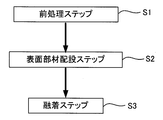
- the manufacturing method of the composite member 1 according to the present invention includes a pretreatment step S1, a surface member disposition step S2 that is a post process of the pretreatment step S1, and the surface member disposition step S2. And a fusion step S3, which is a subsequent process.
- the composite member 1 manufactured by the manufacturing method according to the present invention includes a core material 11 that becomes a core, and a surface member 12 that is fixed to the outer peripheral surface of the core material 11.
- the core material 11 is a member made of a conductive material.
- the shape of the core material 11 is not particularly limited, and various shapes such as a rod shape, a wire shape, a columnar shape, and a hollow cylindrical shape can be adopted.
- the core material 11 it may be comprised from a single material according to the function, or may be comprised from several materials.
- the core material 11 composed of a plurality of materials, for example, two types of wire-like metal members twisted, one obtained by twisting a wire-like metal member and a wire-like resin member, Various materials such as those formed from a material different from the surface part (two-layer structure, for example, a member in which the outer surface of the central part made of metal is coated with a thermosetting resin to form the surface part) The configuration can be adopted.
- the core material 11 is composed of a plurality of materials, at least one kind of material is made easy to conduct electricity, and the core material 11 as a whole is configured to have conductivity.
- the surface member 12 is made of a material having lower magnetism than the core material 11.
- the material having lower magnetism than the core material 11 is a concept including a material having no magnetism in addition to a material having weaker magnetism than the core material 11.
- the surface member 12 may be formed of a material that can easily conduct electricity, or may be formed of a material that does not conduct electricity.
- the surface member 12 may be formed of a metal material such as iron or stainless steel, or may be formed of a synthetic resin material.
- Preferred examples of the synthetic resin material include a fluorine resin, a polyester resin, a polyamide resin, and a polyolefin resin.
- the shape of the surface member 12 is not particularly limited as long as it can be disposed on the outer peripheral surface of the core material 11.
- various shapes such as a wire shape, a granular shape, a belt shape, and a fiber shape can be adopted. What is necessary is just to select suitably as a material of the surface member 12 according to the function (corrosion resistance function, lubricity function, heat insulation function, fatigue resistance function) provided to the composite member 1.
- a material suitable for giving a desired function is selected as the surface member 12. That's fine.
- a plurality of materials each exhibiting a desired function may be selected as the surface member 12.
- Pre-processing step S1 is a foreign matter removing process for removing dirt and dust attached to the outer peripheral surface of the core material 11, a degreasing process for removing oil and fat components such as mineral oil attached to the outer peripheral surface of the core material 11, or This is a process of performing various processes such as a surface processing performed to improve the adhesion between the outer peripheral surface of the core material 11 and the surface member 12.
- pre-processing step S1 you may comprise so that the single process selected from the foreign material removal process, the degreasing process, and the surface processing process may be performed, or you may comprise so that a several process may be performed.
- the foreign matter removing process for example, air is blown to the core material 11 to remove dirt and dust adhering to the outer peripheral surface, water washing process to remove the dirt by washing, and on the outer peripheral surface of the core material 11
- a wiping process or the like for wiping off dirt or the like with a waste cloth or the like can be exemplified.
- the degreasing treatment for example, the core material 11 is immersed in a degreasing solution such as alcohol, acetone, thinner, etc. in a degreasing treatment tank or the like, and the oil and fat components such as mineral oil and dirt adhered to the core material 11 Solvent degreasing which removes can be illustrated.
- heat degreasing to remove oil and fat components on the surface of the core material 11 by applying heat, or ultrasonic waves using a shock wave when a vacuum bubble generated in the liquid by ultrasonic waves bursts In addition to such solvent degreasing, heat degreasing to remove oil and fat components on the surface of the core material 11 by applying heat, or ultrasonic waves using a shock wave when a vacuum bubble generated in the liquid by ultrasonic waves bursts.
- Various degreasing methods such as degreasing and alkaline electrolytic degreasing by immersing the core material 11 in an alkaline cleaning solution and performing electrolysis at a predetermined current density to remove oil and fat components such as mineral oil adhering to the surface of the core material 11 can be applied.
- corrugation of the outer peripheral surface of the core material 11 can be illustrated, for example.
- pre-processing step S1 is a process for improving the adhesive strength of the core material 11 and the surface member 12 in surface member arrangement
- the pretreatment step 12 can be omitted to constitute the present manufacturing method.
- the surface member disposing step S2 is a step of disposing the surface member 12 having lower magnetism than the core material 11 on the outer peripheral surface of the core material 11 made of a conductive material, and is performed after the preprocessing step S1.
- this surface member disposing step S2 various methods for disposing the surface member 12 on the outer peripheral surface of the core member 11 can be adopted.
- the surface member 12 made of a wire is used as the core member 11.
- a method (coating step) for covering the outer peripheral surface of the core material 11 with the surface member 12 by spirally winding the outer peripheral surface of the core member 11 will be described below. This covering step is performed using a covering device 2 as shown in FIG.
- the covering device 2 includes a spool 21 around which a wire is wound around an axis, and a drive device (not shown) that rotates the spool 21 around the axis.
- the axial center of the spool 21 is formed so as to be hollow, and the core material 11 can be inserted into the hollow portion.
- the operation of the covering device 2 will be described. First, the wire (surface member 12) wound around the spool 21 is pulled out, and the tip of the wire (surface member 12) is fixed to the surface of the core material 11. Next, while rotating the spool 21 by the driving device, the core material 11 is moved at a predetermined speed (moved in the direction along the axis of the spool 21) by a separately provided conveying means (not shown).
- the wire material which is the surface member 12 is spirally wound on the outer peripheral surface of the material 11, and the outer peripheral surface of the core material 11 is covered with the surface member 12 made of the wire material as shown in FIG.
- the surface member 12 made of a wire wound around the outer peripheral surface of the core material 11 is appropriately adjusted by adjusting the conveyance speed (movement speed) of the core material 11 by the conveying means and the rotation speed of the spool 21 as appropriate.
- the number of windings of the wire per unit length of the material 11) can be adjusted.
- the surface member 12 and the core material 11 are subjected to electromagnetic induction heating from the outside of the surface member 12 disposed on the outer peripheral surface of the core material 11, so that the surface member is heated by the heat of the heated core material 11.
- electromagnetic induction heating is a kind of heating method that is also used in electromagnetic cookers (IH cooking heaters), high-frequency welding, and the like, and changes in magnetic field (magnetic flux density) are caused by passing an alternating current through the coil.
- an induced current (eddy current) is generated in the conductive material placed in the magnetic field, and the conductive material itself generates heat by its resistance.
- the core material 11 in the composite member 1 manufactured by the manufacturing method according to the present embodiment is a member having higher magnetism than the surface member 12, the core material is higher than the surface member 12 by electromagnetic induction heating by an electromagnetic induction heating device. 11 generates a larger amount of heat, and the temperature of the core material 11 becomes higher than the temperature of the surface member 12. As a result, it is possible to melt at least one of the facing regions 13a and 13b between the surface member 12 and the core material 11.
- the melting point of the surface member 12 when the melting point of the surface member 12 is lower than the melting point of the core material 11, the heat generated by the core material 11 is transmitted to the surface member 12, and the surface member 12 is opposed to the core material 11 (contact region). 13a will melt. Further, since the density of the induced current generated in the electromagnetically heated core material 11 increases from the center of the core material 11 toward the surface thereof, the surface is heated faster than the inside of the core material 11 ( Will be heated in a concentrated manner). Therefore, when the melting point of the core member 11 is lower than the melting point of the surface member 12, the surface of the core member 11 heated in a concentrated manner (the region (contact region) 13b facing the surface member 12 in the core member 11)). Will melt.
- the frequency of the current flowing in the electromagnetic induction heating device (AC current flowing in the coil) high, the heat generating parts in the core material 11 can be collected on the surface, and conversely, the current frequency is lowered. Since the inside of the core material 11 can be uniformly heated by setting, it is preferable to configure the electromagnetic induction heating device so that the frequency of the current flowing through the electromagnetic induction heating device can be changed as appropriate.
- Electromagnetic induction heating is performed by placing the core material 11 having the surface member 12 disposed on the outer peripheral surface in the space 31 at the center of the hollow cylindrical electromagnetic induction heating device 3. After completion of the electromagnetic induction heating for a predetermined time, the core material 11 having the surface member 12 disposed on the outer peripheral surface is taken out from the space portion 31 in the central portion of the hollow cylindrical electromagnetic induction heating device 3, or electromagnetic By stopping the induction heating device, the temperature of the surface member 12 and the core material 11 is lowered, the dissolved region is solidified, and the surface member 12 and the core material 11 are fixed to each other.
- the core material is formed from the outside of the surface member 12. 11 is heated by electromagnetic induction, and at least one of the facing regions 13a and 13b of the surface member 12 and the core material 11 by the heat of the heated core material 11 (the facing region 13a of the surface member 12 facing the core material 11; Or, the region 13b facing the surface member 12 in the core member 11 or both of them is melted, and the fusion step S3 for fusing the surface member 12 to the core member 11 is provided.
- the composite member 1 manufactured by spirally winding a wire made of a corrosion-resistant material as the surface member 12 around the outer peripheral surface of the core 11 made of a long metal wire by the above manufacturing method
- the corrosion resistance which is a material characteristic of the member 12
- it has an excellent flexibility function obtained from the shape characteristics of the outer surface of the composite member 1. That is, it is more excellent in flexibility than the composite member 1 manufactured by simply applying the corrosion-resistant coating to the outer peripheral surface of the core material 11.
- the lubricating oil enters the recess 14 (see FIG. 2) on the outer surface of the composite member 1, This composite member 1 can exhibit the function of being able to hold the lubricating oil for a long period of time.
- the shape such as a wire shape or a particle shape is used.
- a surface member 12 By forming the surface member 12 on the surface, such a surface member 12 can be fused and fixed onto the outer peripheral surface of the core material 11.
- the electromagnetic induction heating device 3 used in the fusion step S3 is a hollow cylindrical type (in the form of a cross-section ring), and the surface member 12 is arranged on the outer peripheral surface.
- the provided core member 11 is arranged in the central space 31 to perform electromagnetic induction heating. That is, since it is configured to surround the periphery of the surface member 12 disposed on the outer peripheral surface of the core material 11 and to perform electromagnetic induction heating, heat is uniformly emitted from the entire outer peripheral surface of the core material 11, The entire region to be dissolved (the facing region 13a of the surface member 12 facing the core member 11 or the facing region 13b of the core member 11 facing the surface member 12 or both) can be uniformly thermally melted. It becomes possible. As a result, the surface member 12 and the core material 11 disposed on the outer peripheral surface of the core material 11 can be bonded with a uniform fixing force without unevenness.
- electromagnetic induction heating is performed by selecting the material of the surface member 12 and the core material 11 so that the melting point of the surface member 12 is lower than the melting point of the core material 11.
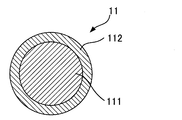
- the heat of the core material 11 allows the facing region (contact region) 13a of the surface member 12 with the core material 11 to be melted before the core material 11, so that the shape of the core material 11 is melted by heat. Therefore, only the surface member 12 can be surely dissolved and the surface member 12 can be fused and fixed on the outer peripheral surface of the core member 11 without being damaged by the above.
- the core material 11 is formed so that the center portion 111 and the surface portion 112 are made of different materials, and the surface member in the core material 11 is formed.
- the surface portion 112 of the core material 11 corresponding to the region (contact region) 13b facing the surface 12 may be configured to be thermally melted by electromagnetic induction heating. Even in such a configuration, the surface portion 112 of the heat-dissolved core material 11 is solidified by being cooled, so that the surface member 12 and the core material 11 can be firmly fused (fixed). .
- the central portion 111 of the core material 11 is formed of a material having a relatively high melting point, such as iron or stainless steel, and the surface portion 112 of the core material 11 is made of zinc or tin having a lower melting point than the central portion 111. It forms with metal materials, such as.
- a core material 11 is heated by electromagnetic induction in the fusion step S3
- the surface portion 112 having a melting point lower than that of the central portion 111 is first melted by heat, and the material of the surface portion 112 is cooled.
- the surface member 12 surface member 12 disposed on the surface portion 112 of the core material 11
- the outer peripheral surface of the core material 11 is fixed to the core material 11.
- the material of the surface member 12 may be selected so that the facing region 13a of the surface member 12 facing the core member 11 is thermally melted.
- the surface member 12 may be selected such that the region 13a facing the core material 11 is not thermally melted, and the range of material selection for the surface member 12 is widened.
- the central portion 111 is composed of different materials.
- the core material 11 may be configured to include a plurality of layers 111a, 111b, and 111c. Further, as the core material 11, the material of the surface portion 112 is configured to have a lower melting point than the center portion 111, and the core material 11 may be configured to have conductivity as a whole.
- the surface portion 112 may be composed of a conductive material, or the center portion 111 may be composed of a conductive material, and the surface portion 112 may be composed of a material that is difficult to conduct electricity. Good.
- the core material 11 in which the surface member 12 is disposed on the outer peripheral surface by electromagnetic induction heating, it is necessary to heat the core material 11 more preferentially than the surface member 12. It is formed from a material having lower magnetism than the core material 11.
- the manufacturing method of the composite member 1 which concerns on this invention was demonstrated, a specific structure is not limited to the said embodiment.
- the composite member 1 is manufactured so as to include the adhesive layer forming step S4 between the pretreatment step S1 and the surface member disposing step S2. May be.
- This adhesive layer forming step S4 includes a coating step S41 and a drying step S42.
- the application step S ⁇ b> 41 is a process of applying an adhesive having a melting point lower than the melting point of the core material 11 to the outer peripheral surface of the core material 11.
- an adhesive layer is formed on the outer peripheral surface of the core material 11 by spraying the adhesive atomized by a spray gun or the like onto the outer peripheral surface of the core material 11.
- a method (spray method) or a method (dipping method) in which the core material 11 is immersed in a storage tank in which the adhesive is stored to form an adhesive layer on the outer peripheral surface (outer surface) of the core material 11 is employed. be able to.
- the adhesive used in the adhesive layer forming step S4 is not particularly limited as long as the surface member 12 can be maintained at a desired position on the outer peripheral surface of the core material 11 by the adhesive force.
- the melting point of the agent may be approximately equal to or lower than the melting point of the surface member 12, or the melting point of the adhesive may be higher than the melting point of the surface member 12.
- the adhesive having high thermal conductivity capable of efficiently transmitting the heat of the heated core material 11 to the surface member 12. Is preferably selected.
- what has various functions can be selected as an adhesive agent.
- a composite member further having a heat insulating function exhibited by the adhesive can be manufactured. It becomes possible.
- a hot melt adhesive mainly composed of a thermoplastic resin can also be used. When this hot melt adhesive is used, the hot melt adhesive is heated and melted and then applied to the outer peripheral surface of the core material 11.
- the drying step S42 is a process of drying the adhesive applied to the outer peripheral surface of the core material 11 and, for example, applies a predetermined amount of air to the core material 11 to which the adhesive has been applied by an air blowing means. Dry the agent.
- a ventilation means may be provided with a heat generating body, and it may comprise so that a warm air may be sprayed with respect to the core material 11 with which the adhesive agent was apply
- the adhesive layer forming step S4 (application step S41) in which an adhesive having a melting point lower than the melting point of the core material 11 is applied to the outer peripheral surface of the core material 11 as a previous stage of the surface member disposing step S2.
- a member having a melting point lower than the melting point of the core material 11 is used as the surface member 12 and the adhesive used in the adhesive layer forming unit 5 has a melting point of the surface.
- the core member 11 is heated by electromagnetic induction, thereby causing the surface member 12 to face the core member 11 and between the surface member 12 and the core member 11.
- the intervening adhesive can be dissolved, and the surface member 12 can be more firmly fixed to the core material 11.
- the melted adhesive enters the gap between the adjacently disposed wire rod and granular member (surface member 12). It can be fixed.
- an adhesive interposed between the surface member 12 and the core material 11 is obtained by heating the core material 11.
- dissolved adhesive approachs the clearance gap between the surface members 12 arrange
- the adhesive layer forming step S4 which is the previous stage of disposing the surface member 12 on the outer peripheral surface of the core material 11, includes a drying step S42 for drying the adhesive applied to the outer peripheral surface of the core material 11. Since it comprises, the surface member 12 can be arrange
- the adhesive may remain on the outer surface of the composite member 1 finally obtained.
- the liquid (or semi-liquid) adhesive may flow along the outer peripheral surface of the core material 11, and the adhesive may not be distributed with a uniform thickness on the outer peripheral surface of the core material 11.
- electromagnetic induction heating is performed in such a case, for example, the adhesive and / or the surface member 12 is melted in the facing region 13a of the core member 11 to fix the surface member 12 to the core member 11.
- the adhesion force between the surface member 12 and the core material 11 may be reduced in a portion where the surface material 12 is thinly applied to the surface of the core material 11.
- the adhesive applied to the outer peripheral surface of the core material 11 is dried, and then the surface member 12 is applied to the outer peripheral surface of the core material 11.
- the adhesive applied to the outer peripheral surface of the core material 11 is dried, and then the surface member 12 is applied to the outer peripheral surface of the core material 11.
- mold shown in FIG. 4 is employ
- the structure can change the magnetic field (magnetic flux density) to the core member 11 on which the surface member 12 is disposed in the surface member disposing step S2 and generate an eddy current in the core member 11, whichever The thing of such a shape may be sufficient.
- a core material in which a plate-like one used for an electromagnetic cooker (IH cooking heater) is adopted as the electromagnetic induction heating device 3 and the surface member 12 is disposed in the vicinity of the plate-like electromagnetic induction heating device 3. You may comprise so that the core material 11 may be heated by arrange
- the surface member 12 which consists of a wire is used for the outer peripheral surface of the core material 11 as the arrangement
- the method of covering the outer peripheral surface of the core material 11 with the surface member 12 by winding in a spiral manner has been described, the surface member 12 is disposed on the outer peripheral surface of the core material 11
- the method (coating step) to be performed is not particularly limited to such a method.
- the surface member 12 may or may not overlap with the winding pitch.
- the belt-shaped surface member 12 is spirally wound on the outer peripheral surface of the core material 11 while rotating the core material 11 in this way.
- the outer peripheral surface of the core material 11 may be covered with the surface member 12 by spraying a granular or fibrous surface member 12 on the outer peripheral surface of the core material 11.
- the granular or fibrous surface member 12 is sprayed and disposed on the outer peripheral surface of the core material 11, for example, the outer surface of the core material 11 is charged so as to have a positive charge, and the granular or fibrous surface is used. It is preferable that the member 12 is charged so as to have a negative charge so that the granular or fibrous surface member 12 adheres to the outer peripheral surface of the core material 11.
- the coating step S41 in the adhesive layer forming step S4 is provided (by omitting the drying step S42) to constitute the method for manufacturing the composite member 1, and toward the adhesive layer that is not dried. It is preferable that the granular or fibrous surface member 12 be sprayed.
Landscapes
- Engineering & Computer Science (AREA)
- Mechanical Engineering (AREA)
- Chemical & Material Sciences (AREA)
- Organic Chemistry (AREA)
- Health & Medical Sciences (AREA)
- General Health & Medical Sciences (AREA)
- Heart & Thoracic Surgery (AREA)
- Vascular Medicine (AREA)
- Physics & Mathematics (AREA)
- Plasma & Fusion (AREA)
- Thermal Sciences (AREA)
- Lining Or Joining Of Plastics Or The Like (AREA)
- Powder Metallurgy (AREA)
- Wire Processing (AREA)
- Laminated Bodies (AREA)
- General Induction Heating (AREA)
Description
本発明は、複合部材の製造方法に関する。特に芯材の外周面に表面部材を固着して製造される複合部材の製造方法に関する。
従来、芯材となる部材の外表面に、芯材とは異なる材料により形成される被覆層を施して製造される種々の複合部材からなる器具が知られている。例えば、血管内治療に使用される医療用ガイドワイヤーや、放電加工に用いられる電極線、断熱配管等種々のものが知られている。
血管内治療に使用される医療用ガイドワイヤーは、金属製の線状芯材の表面を樹脂によって被覆し、かつ樹脂の表面には親水性処理を施して製造される(例えば特許文献1)。芯材の表面を樹脂で被覆する手法としては種々のものを採用することができるが、例えば、高温下で液体状に生成した樹脂が貯留される貯留槽内に線状芯材を浸漬した後、冷却することにより線状芯材の表面に樹脂層を形成する方法が知られている。
ワイヤ放電加工用電極線は、例えば、Cu合金からなる芯材の周りに、Cu-Zn合金層を被覆して製造される(例えば特許文献2)。芯材の表面にCu-Zn合金層を形成する手法としては、芯材の表面にZnメッキを施す方法が知られている。
断熱配管としては、種々の形態のものが存在するが、例えば、放熱を防止しつつ液体を供給する際に用いられる断熱配管は、金属製の配管の外周面にシート状の断熱材を巻き付けて製造される。
上述のように、芯材となる部材の外表面に、芯材とは異なる材料により形成される被覆層を施して所望の複合部材を製造する方法は種々案出されている。本発明は、これらのような製造方法とは全く異なる新規な製造方法、特に、芯材の外周面に表面部材を固着して製造される複合部材の新規な製造方法を提供することを目的とする。
本発明の上記目的は、芯材の外周面に表面部材が固着された複合部材の製造方法であって、導電性材料からなる芯材の外周面に、前記芯材よりも磁性が低い表面部材を配設する表面部材配設ステップと、前記表面部材の外側から前記芯材を電磁誘導加熱し、加熱された前記芯材の熱によって前記表面部材と前記芯材との対向領域の少なくともいずれか一方を溶融させて、前記表面部材を前記芯材に融着させる融着ステップとを備える複合部材の製造方法より達成される。
このような複合部材の製造方法によれば、溶融させる部分が、前記表面部材と前記芯材との対向領域の少なくともいずれか一方(表面部材における芯材との対向領域、又は、芯材における表面部材との対向領域、或いは、その両方)であるため、表面部材の外表面の形状を熱溶解によって損なうこと無く当該表面部材を芯材の外周面上に確実に融着固定させることが可能となる。また、芯材の外周面上に表面部材を配置する段階において、液体状に生成することが困難な材料を表面部材として選択する場合であっても、線材状或いは粒子状等の形態に表面部材を形成することにより、このような表面部材を芯材の外周面上に融着させることが可能となる。
この複合部材の製造方法において、前記表面部材の融点は、前記芯材の融点よりも低いことが好ましい。
このように、芯材の外周面に配設される表面部材を、芯材に用いられる材料の融点よりも低い材料により構成することにより、電磁誘導加熱される芯材の熱によって、前記表面部材における前記芯材との対向領域を芯材よりも先に溶融させることが可能となるため、芯材の形状を熱溶解によって損なうことなく、表面部材のみを確実に溶解させて、当該表面部材を芯材の外周面上に融着固定させることが可能となる。
また、本発明の上記目的は、前記芯材が、中心部分と表面部分とを備えており、電磁誘導加熱された前記芯材の熱によって前記芯材の前記表面部分を溶融させて、前記表面部材を前記芯材に融着させることが好ましい。
このような複合部材の製造方法によれば、熱溶解させる部分が、芯材における表面部材との対向領域に相当する芯材の表面部分であるため、表面部材の外表面の形状を熱溶解によって損なうこと無く当該表面部材を芯材の外周面上に確実に融着固定させることが可能となる。
また、前記表面部材配設ステップの前段階として、前記芯材の融点よりも低い融点を有する接着剤を前記芯材の外周面に塗布する接着剤層形成ステップを備えることが好ましい。
このように、芯材の融点よりも低い融点を有する接着剤を芯材の外周面に塗布した後に、表面部材を芯材の外周面に配設して、表面部材の外側から芯材を電磁誘導加熱することにより、例えば、表面部材として、芯材の融点よりも低い融点を有する部材を用いると共に、接着剤層形成手段において用いられる接着剤として、接着剤の融点が、表面部材の融点と略同等以下のものを採用した場合、芯材を加熱することにより、表面部材における芯材との対向領域及び表面部材と芯材との間に介在する接着剤を溶解させることができ、表面部材をより一層強固に芯材に固着することができる。具体的に説明すると、表面部材として、芯材の外周面に螺旋状に巻回して配置される線材や、或いは、吹き付けることにより芯材の外周面に配置される粒状或いは繊維状の部材を使用する場合には、溶解した接着剤が、隣接して配置される線材や粒状の部材の隙間に進入することになるため、確実に表面部材を芯材に固着させることが可能となる。
また、前記接着剤層形成ステップは、前記芯材の外周面に塗布された接着剤を乾燥させる乾燥ステップを備えることが好ましい。
このように、表面部材を芯材の外周面に配設する前段階において、芯材の外周面に塗布した接着剤を乾燥させることにより、接着剤の接着力が失われた状態で表面部材を芯材の外周面に配設することが可能となる。接着剤の接着力が存在する状況下、つまり、接着剤が乾燥していない状態でも表面部材を芯材の外周面上に配設してもよいが、接着剤が乾燥しておらず、接着剤が液体状或いは半液体状の状態で表面部材を芯材の外周面に配設する場合、配設された表面部材の周りから液体状(或いは半液体状)の接着剤が浸み出て、最終的に得られる複合部材の外表面に接着剤が残ってしまうおそれがある。或いは、液体状(或いは半液体状)の接着剤が芯材の外周面上に沿って流動し、接着剤が芯材の外周面上に均一に分布しなくなるおそれがある。このような場合に電磁誘導加熱を行うと、例えば、接着剤及び/又は表面部材における芯材との対向領域を溶融させて、表面部材を芯材に固着する際に、接着剤が薄く芯材表面に塗布されている部分における表面部材と芯材との固着力が低下する恐れがある。一方、表面部材を芯材の外周面に配設する前段階において、芯材の外周面に塗布した接着剤を乾燥させた後に、表面部材を芯材の外周面に配設する場合には、上述したような事態(接着剤の浸出や、接着剤の不均一分布)が発生することを効果的に防止することができ、最終的に得られる複合部材の外表面に接着剤が残ってしまったり、表面部材と芯材との固着力が低下する部分が発生することを確実に防止することができる。
また、前記表面部材配設ステップは、線材からなる表面部材を前記芯材の外周面に巻回することにより、前記芯材の外周面を前記表面部材で被覆する被覆ステップを備えることが好ましい。また、前記表面部材配設ステップは、粒状或いは繊維状の表面部材を前記芯材の外周面に吹き付けることにより、前記芯材の外周面を前記表面部材で被覆する被覆ステップを備えることが好ましい。
本発明によれば、芯材の外周面に表面部材を固着して製造される複合部材の新規な製造方法を提供することができる。
以下、本発明の実施形態にかかる芯材の外周面に表面部材を固着して製造される複合部材の製造方法について添付図面を参照して説明する。図1は、本発明の一実施形態に係る複合部材1の製造方法の工程を示すブロック図である。図1に示すように、本発明に係る複合部材1の製造方法は、前処理ステップS1と、当該前処理ステップS1の後工程である表面部材配設ステップS2と、当該表面部材配設ステップS2の後工程である融着ステップS3とを備えている。
ここで、本発明に係る製造方法により製造される複合部材1は、図2の断面図に示すように、コアとなる芯材11と、芯材11の外周面に固着される表面部材12とを備えている。なお、図2の断面図は、複合部材1の軸心に沿って切断した断面図を表している。芯材11は、導電性材料からなる部材である。芯材11の形状には特に限定はなく、棒状や線材状、円柱状、中空円筒状等、種々の形状を採用することができる。また、芯材11としては、その機能に応じて単一の材料から構成されるものであってもよく、或いは、複数の材料から構成されるものであってもよい。複数の材料から構成される芯材11としては、例えば、2種類の線材状の金属部材を撚ったものや、線材状の金属部材及び線材状の樹脂部材を撚ったもの、中心部分と表面部分とが異なる材料から形成されているもの(二層構造のもの、例えば、金属からなる中心部分の外表面に熱硬化性樹脂をコーティングして表面部分を構成したような部材)等、種々の構成を採用することができる。芯材11を複数の材料から構成する場合には、少なくとも一種類の材料が電気を通しやすい材料とし、芯材11全体として導電性を備えるように構成する。
表面部材12は、芯材11よりも磁性が低い材料から形成されている。芯材11よりも磁性が低い材料とは、芯材11よりも磁性が弱い材料の他、磁性が無い材料を含む概念である。この表面部材12は、電気を通しやすい材料によって形成してもよく、あるいは、電気を通さない材料によって形成してもよい。表面部材12としては、例えば、鉄やステンレス等の金属材料から形成してもよく、或いは、合成樹脂材料から形成してもよい。合成樹脂材料としては、フッ素系樹脂、ポリエステル系樹脂、ポリアミド系樹脂、ポリオレフィン系樹脂等を好適に例示できる。表面部材12の形状も特に限定はなく、芯材11の外周面に配置可能であればよい。例えば、線材状や粒状、帯状、繊維状等、種々の形状を採用可能である。表面部材12の材料としては、複合部材1に付与する機能(耐食性機能、潤滑性機能、断熱性機能、耐疲労性機能)に応じて適宜選択すればよい。例えば、耐食性機能、潤滑性機能、断熱性機能、耐疲労性機能といった各種機能から選択した1つの機能を付与する場合には、所望する機能を付与するに適した材料を表面部材12として選択すればよい。或いは、複数の機能を同時に付与するような場合には、所望の機能をそれぞれ発揮する複数の材料を表面部材12として選択すればよい。
前処理ステップS1は、芯材11の外周面に付着する汚れや埃などを除去する異物除去処理や、芯材11の外周面に付着する鉱物油等の油脂成分を除去する脱脂処理、或いは、芯材11の外周面と表面部材12との密着性を向上させるために行われる表面加工処理等の各種処理を行う工程である。前処理ステップS1としては、異物除去処理、脱脂処理及び表面加工処理から選択した単一の処理を行うように構成してもよく、或いは、複数の処理を行うように構成してもよい。ここで、異物除去処理としては、例えば、芯材11にエアーを吹き付けて外周面に付着する汚れや埃を除去するエアー処理や、水洗いにより汚れを除去する水洗い処理、芯材11の外周面上の汚れ等をウエス等により拭き取る拭き取り処理等を例示することができる。また、脱脂処理としては、例えば、脱脂用の処理槽等にアルコールやアセトン、シンナー等の脱脂処理液内に芯材11を浸漬させて、芯材11に付着した鉱物油等の油脂成分や汚れを取り除く溶媒脱脂を例示することができる。また、このような溶媒脱脂の他、熱を加えて芯材11表面の油脂成分を除去する加熱脱脂、或いは、超音波によって液体に生じた真空の気泡が破裂する際の衝撃波を利用した超音波脱脂、芯材11をアルカリ洗浄液中に浸漬しつつ、所定の電流密度の電解をかけて芯材11表面に付着している鉱物油等の油脂成分を除去するアルカリ電解脱脂等、種々の脱脂手法を適用することができる。また、表面加工処理としては、例えば、芯材11の外周面の凹凸性を向上させるためのブラスト加工を例示することができる。なお、前処理ステップS1は、後述する表面部材配設ステップS2において、芯材11と表面部材12との密着強度を高めるための工程であるため、かかる前処理ステップS1を備えなくても十分な芯材11と表面部材12との密着強度を得られるような場合には、前処理ステップ12を省略して本製造方法を構成することができる。
表面部材配設ステップS2は、導電性材料からなる芯材11の外周面に、芯材11よりも磁性が低い表面部材12を配設する工程であり、前処理ステップS1の後に行われる。この表面部材配設ステップS2は、芯材11の外周面上に表面部材12を配設するための種々の方法を採用することができるが、一例として、線材からなる表面部材12を芯材11の外周面に螺旋状に巻回することにより、芯材11の外周面を表面部材12で被覆する方法(被覆ステップ)について以下説明する。この被覆ステップは、図3に示すようなカバリング装置2を用いて行われる。このカバリング装置2は、線材が軸心に巻かれたスプール21と、当該スプール21をその軸心を中心として回転させる駆動装置(図示せず)とを備えている。スプール21の軸心は中空となるように形成されており、この中空部内に芯材11が挿入可能となるように構成されている。このカバリング装置2の作動について説明すると、まず、スプール21に巻かれた線材(表面部材12)を引き出して、線材(表面部材12)の先端を芯材11表面に固定する。次いで、駆動装置によってスプール21を回転させつつ、別途設けられる搬送手段(図示せず)により芯材11を所定の速度で移動(スプール21の軸心に沿った方向へ移動)させることにより、芯材11の外周面上に表面部材12である線材が螺旋状に巻回されて、図2に示すように芯材11の外周面が線材からなる表面部材12で被覆されることとなる。なお、搬送手段による芯材11の搬送速度(移動速度)や、スプール21の回転数を適宜調整することにより、芯材11の外周面に巻回される線材からなる表面部材12の粗密(芯材11単位長さ当たりの線材の巻回数)を調整することが可能となる。
融着ステップS3は、芯材11の外周面に配設された表面部材12の外側から表面部材12及び芯材11を電磁誘導加熱することにより、加熱された芯材11の熱によって、表面部材12と芯材11との対向領域13a,13bの少なくともいずれか一方を溶融させて、表面部材12を芯材11に融着させる工程である。ここで、電磁誘導加熱とは、電磁調理器(IHクッキングヒーター)や高周波溶接等にも利用されている加熱方式の一種であり、コイルに交流電流を流すことにより磁界(磁束密度)の変化を生じさせ、その磁界内に置いた導電性物質に誘導電流(渦電流)を発生させて、その抵抗により導電性物質自体を発熱させる原理を利用した加熱方式である。本実施形態に係る製造方法により製造される複合部材1における芯材11は、表面部材12よりも磁性が高い部材であるため、電磁誘導加熱装置による電磁誘導加熱によって、表面部材12よりも芯材11の方の発熱量が大きくなり、表面部材12の温度よりも芯材11の温度の方が高くなる。これにより、表面部材12と芯材11との対向領域13a,13bの少なくともいずれか一方を溶融させることが可能となる。例えば、表面部材12の融点が芯材11の融点よりも低い場合には、芯材11が発した熱が表面部材12に伝わって、表面部材12における芯材11との対向領域(接触領域)13aが溶融することとなる。また、電磁誘導加熱された芯材11に生じる誘導電流の密度は、芯材11の中心からその表面に近いほど高くなることから、芯材11の内部に比べてその表面の方が早く加熱(集中して加熱)されることとなる。したがって、芯材11の融点が表面部材12の融点よりも低い場合には、集中して加熱される芯材11の表面(芯材11における表面部材12との対向領域(接触領域)13bが)が溶融することとなる。ここで、電磁誘導加熱装置に流れる電流(コイルに流れる交流電流)の周波数を高く設定することにより、芯材11において発熱する部位をその表面に集めることができ、逆に、電流の周波数を低く設定することにより芯材11の内部も均一に発熱させることができるため、電磁誘導加熱装置に流れる電流の周波数を適宜変更できるように、電磁誘導加熱装置を構成することが好ましい。
この融着ステップS3において使用される電磁誘導加熱装置としては、例えば、図4に示すように、中空筒状型の形状のものを好適に使用することができる。中空筒状型電磁誘導加熱装置3の中央部における空間部31に、外周面上に表面部材12が配設された芯材11を配置して電磁誘導加熱を行う。所定時間の電磁誘導加熱が終了した後、中空筒状型電磁誘導加熱装置3の中央部における空間部31から、外周面上に表面部材12が配設された芯材11を取り出す、或いは、電磁誘導加熱装置を停止させることにより、表面部材12や芯材11の温度が低下し、溶解していた領域が固化して、表面部材12と芯材11とが互いに固着される。
上記実施形態に係る複合部材1の製造方法は、導電性材料からなる芯材11の外周面に芯材11よりも磁性が低い表面部材12を配設した後、表面部材12の外側から芯材11を電磁誘導加熱して、加熱された芯材11の熱によって表面部材12と芯材11との対向領域13a,13bの少なくともいずれか一方(表面部材12における芯材11との対向領域13a、又は、芯材11における表面部材12との対向領域13b、或いは、その両方)を溶融させて、表面部材12を芯材11に融着させる融着ステップS3を備えるように構成しているため、芯材11の表面に配設された表面部材12の外表面の形状を熱溶解によって損なうこと無く当該表面部材12を芯材11の外周面上に確実に融着固定させることが可能となる。従って、複合部材1の外側に配設される部材(芯材11の外周面上に固着される表面部材12)の材料的特性と、複合部材1の外表面の形状的特性とを組み合わせた機能を複合部材1に付与することが可能となる。例えば、上記製造方法により、長尺状の金属製線材からなる芯材11の外周面に、表面部材12として耐食性のある材料からなる線材を螺旋状に巻回して製造した複合部材1は、表面部材12の材料的特性である耐食性に加えて、複合部材1の外表面の形状的特性から得られる優れた可撓性機能を有するものとなる。つまり、単に芯材11の外周面に耐食性コーティングを施して製造した複合部材1よりも、より一層可撓性に優れたものとなる。また、このようにして得られる複合部材1の外表面に潤滑油を浸潤させるような場合には、複合部材1の外表面の凹部14(図2参照)に潤滑油が入り込むことになるため、この複合部材1は、潤滑油を長期間保持することができるという機能を発揮することができる。
また、芯材11の外周面上に表面部材12を配置する段階において、液体状に生成することが困難な材料を表面部材12として選択する場合であっても、線材状或いは粒子状等の形態に表面部材12を形成することにより、このような表面部材12を芯材11の外周面上に融着させて固着することが可能となる。
また、上記実施形態においては、融着ステップS3にて使用する電磁誘導加熱装置3として中空筒状型のもの(断面リング状の形態のもの)を採用し、表面部材12が外周面上に配設された芯材11を中央部の空間部31に配置して電磁誘導加熱を行うように構成している。つまり、芯材11の外周面上に配設された表面部材12の周囲を取り囲んで電磁誘導加熱するように構成しているため、芯材11の外周面全域から均一に熱が発せられ、熱溶解させようとする領域(表面部材12における芯材11との対向領域13a、又は、芯材11における表面部材12との対向領域13b、或いは、その両方)の全体を均一に熱溶解させることが可能となる。この結果、芯材11の外周面に配設される表面部材12と芯材11とをムラなく均一な固着力でもって結合することができる。
また、このような複合部材1の製造方法において、表面部材12の融点が、芯材11の融点よりも低くなるように、表面部材12及び芯材11の材料を選定することにより、電磁誘導加熱される芯材11の熱によって、表面部材12における芯材11との対向領域(接触領域)13aを芯材11よりも先に溶融させることが可能となるため、芯材11の形状を熱溶解によって損なうことなく、表面部材12のみを確実に溶解させて、当該表面部材12を芯材11の外周面上に融着固定させることが可能となる。
また、このような複合部材1の製造方法において、例えば、図5に示すように、中心部分111と表面部分112とが異なる材料となるように芯材11を形成し、芯材11における表面部材12との対向領域(接触領域)13bに相当する芯材11の表面部分112が、電磁誘導加熱によって熱溶解するように構成してもよい。このような構成であっても、熱溶解した芯材11の表面部分112が、冷却されることにより固化する結果、表面部材12と芯材11とを強固に融着(固着)させることができる。
具体的には、例えば、芯材11の中心部分111を鉄やステンレス等の比較的融点が高い材料により形成すると共に、芯材11の表面部分112を中心部分111よりも融点の低い亜鉛や錫等の金属材料により形成する。このような芯材11を、融着ステップS3において電磁誘導加熱した場合に、中心部分111よりも融点の低い表面部分112が先に熱溶解することとなり、この表面部分112の材料が冷却されて固化することによって、芯材11の外周面に配設されている表面部材12(芯材11の表面部分112上に配設された表面部材12)が、芯材11と固着することとなる。複合部材の製造方法をこのような構成とする場合、表面部材12における芯材11との対向領域13aが熱溶解するように表面部材12の材料を選定してもよく、或いは、表面部材12における芯材11との対向領域13aが熱溶解しないような表面部材12を選定してもよく、表面部材12の材料選択の幅が広がることとなる。
また、図5に示す芯材11は、中心部分111と表面部分112とを備える2層構造を有するものであるが、例えば、図6に示すように、中心部分111が、それぞれ異なる材料により構成される複数の層111a,111b,111cを備えるように芯材11を構成してもよい。また、芯材11としては、表面部分112の材料が中心部分111よりも融点が低くなるように構成すると共に、芯材11全体として導電性を備えるように構成すればよいため、中心部分111を電気を通しにくい材料により構成し、表面部分112を導電性材料により構成してもよく、或いは、中心部分111を導電性材料により構成し、表面部分112を電気を通しにくい材料により構成してもよい。なお、電磁誘導加熱により表面部材12が外周面に配設された芯材11を加熱する際に、表面部材12よりも優先的に芯材11を加熱する必要があることから、表面部材12は、芯材11よりも磁性が低い材料から形成されている。
以上、本発明に係る複合部材1の製造方法について説明したが、具体的構成は、上記実施形態に限定されない。例えば、上記実施形態において、図7のブロック図に示すように、前処理ステップS1と表面部材配設ステップS2との間に、接着剤層形成ステップS4を備えるようにして複合部材1を製造してもよい。
この接着剤層形成ステップS4は、塗布ステップS41と乾燥ステップS42とを備えている。塗布ステップS41は、芯材11の融点よりも低い融点を有する接着剤を芯材11の外周面に塗布する工程である。芯材11の外周面に接着剤を塗布する方法としては、スプレーガン等により霧化した接着剤を芯材11の外周面に吹き付けることにより芯材11の外周面上に接着剤層を形成する方法(スプレー方式)や、接着剤が貯留される貯留槽内に芯材11を浸漬させて芯材11の外周面(外表面)に接着剤層を形成する方法(ディッピング方式)等を採用することができる。なお、接着剤層形成ステップS4において用いられる接着剤としては、その接着力により、芯材11の外周面の所望位置に表面部材12を配設した状態を維持できれば特に限定されず、例えば、接着剤の融点が、表面部材12の融点と略同等以下のものを採用してもよく、或いは、接着剤の融点が、表面部材12の融点以上のものを採用してもよい。ここで、接着剤として、その融点が表面部材12の融点よりも大きいものを採用する場合、加熱された芯材11の熱を、効率よく表面部材12に伝えることができる熱伝導性の高いものを選定することが好ましい。また、接着剤としては、種々の機能を有するものを選択することができる。例えば、接着剤として断熱性に富むものを採用した場合には、芯材が発揮する機能及び表面部材が発揮する機能の他、接着剤が発揮する断熱機能を更に有する複合部材を製造することが可能となる。また、接着剤としては、熱可塑性樹脂を主成分としたホットメルト接着剤を使用することもできる。このホットメルト接着剤を使用する場合には、当該ホットメルト接着剤を加熱溶融させた後、芯材11の外周面に塗布する。
乾燥ステップS42は、芯材11の外周面に塗布された接着剤を乾燥させる工程であり、例えば、送風手段により、接着剤が塗布された芯材11に対して所定風量の風を当てて接着剤の乾燥を行う。なお、送風手段が発熱体を備えるように構成し、接着剤が塗布された芯材11に対して温風を吹き付けるように構成してもよく、或いは、風を吹き付けずに自然乾燥によって接着剤を乾燥させてもよい。
このように、表面部材配設ステップS2の前段階として、芯材11の融点よりも低い融点を有する接着剤を芯材11の外周面に塗布する接着剤層形成ステップS4(塗布ステップS41)を備えるように構成する場合、例えば、表面部材12として、芯材11の融点よりも低い融点を有する部材を用いると共に、接着剤層形成手段5において用いられる接着剤として、接着剤の融点が、表面部材12の融点と略同等以下のものを採用した場合、芯材11を電磁誘導加熱することにより、表面部材12における芯材11との対向領域13a及び表面部材12と芯材11との間に介在する接着剤を溶解させることができ、表面部材12をより一層強固に芯材11に固着することができる。具体的に説明すると、表面部材12として、芯材11の外周面に螺旋状に巻回して配置される線材や、或いは、吹き付けることにより芯材11の外周面に配置される粒状或いは繊維状の部材を使用する場合には、溶解した接着剤が、隣接して配置される線材や粒状の部材(表面部材12)の隙間に進入することになるため、確実に表面部材12を芯材11に固着させることが可能となる。また、表面部材12として、芯材11の融点よりも高い融点を有する部材を用いた場合には、芯材11を加熱することにより表面部材12と芯材11との間に介在する接着剤が溶解し、この溶解した接着剤が、隣接して配置される表面部材12の隙間に進入して、表面部材12と芯材11とを確実に固着させることが可能となる。また、接着剤として、表面部材12の融点よりも高い融点を有するものを用いた場合であっても、芯材11の熱が、接着剤層を介して表面部材12に伝わることにより、表面部材12における芯材11との対向領域13aを溶解させることが可能であり、この溶解した対向領域13aが冷却されることにより、接着剤層を介して、表面部材12を芯材11上に固着させることができる。
また、表面部材12を芯材11の外周面に配設する前段階である接着剤層形成ステップS4が、芯材11の外周面に塗布された接着剤を乾燥させる乾燥ステップS42を備えるように構成しているため、接着剤の接着力が失われた状態で表面部材12を芯材11の外周面に配設することが可能となる。接着剤の接着力が存在する状況下、つまり、接着剤が乾燥していない状態でも表面部材12を芯材11の外周面上に配設してもよいが、接着剤が乾燥しておらず、接着剤が液体状或いは半液体状の状態で表面部材12を芯材11の外周面に配設する場合、配設された表面部材12の周りから液体状(或いは半液体状)の接着剤が浸み出て、最終的に得られる複合部材1の外表面に接着剤が残ってしまうおそれがある。或いは、液体状(或いは半液体状)の接着剤が芯材11の外周面上に沿って流動し、接着剤が芯材11の外周面上に均一の厚さで分布しなくなるおそれがある。このような場合に電磁誘導加熱を行うと、例えば、接着剤及び/又は表面部材12における芯材11との対向領域13aを溶融させて表面部材12を芯材11に固着する際に、接着剤が薄く芯材11表面に塗布されている部分において表面部材12と芯材11との固着力が低下する恐れがある。これに対し、表面部材12を芯材11の外周面に配設する前段階において、芯材11の外周面に塗布した接着剤を乾燥させ、その後に表面部材12を芯材11の外周面に配設する場合には、上述したような接着剤の浸出や接着剤の厚み分布が不均一になることを効果的に防止することができ、最終的に得られる複合部材1の外表面に接着剤が残留することや、表面部材12と芯材11との固着力が低下する部分が発生することを確実に防止することができる。
また、上記実施形態においては、融着ステップS3において使用される電磁誘導加熱装置3として、図4に示す中空筒状型の形状のものを採用しているが、このような構成に特に限定されず、表面部材配設ステップS2により表面部材12が配設された芯材11に対して磁界(磁束密度)を変化させて芯材11に渦電流を発生させることができる構成であれば、どのような形状のものであってもよい。例えば、電磁調理器(IHクッキングヒーター)に用いられるような、プレート状のものを電磁誘導加熱装置3として採用し、当該プレート状電磁誘導加熱装置3の近傍に表面部材12が配設された芯材11を配置することにより芯材11を加熱するように構成してもよい。
また、上記実施形態においては、表面部材配設ステップS2における芯材11の外周面への表面部材12の配設方法(被覆ステップ)として、線材からなる表面部材12を芯材11の外周面に螺旋状に巻回することにより、芯材11の外周面を表面部材12で被覆する方法(カバリング装置2を用いた方法)について説明したが、芯材11の外周面に表面部材12を配設する方法(被覆ステップ)はこのような方法に特に限定されない。例えば、芯材11を回転させることにより、線材状或いは帯状の表面部材12を芯材11の外周面上に螺旋状に巻回して、芯材11の外周面を表面部材12で被覆する方法を採用してもよい。なお、帯状の表面部材12を芯材11上に巻回して配設する場合、巻回するピッチについては、表面部材12が重なってもよく、或いは重ならなくてもよい。ここで、芯材11の径が比較的太い棒状の形状を有する場合、このように芯材11を回転させながら帯状等の表面部材12を芯材11の外周面上に螺旋状に巻回する方法を採用することにより、効率よく表面部材12を芯材11上に配設することができる。また、芯材11の外周面に、粒状或いは繊維状の表面部材12を吹き付けることにより、芯材11の外周面を表面部材12で被覆するようにしてもよい。粒状或いは繊維状の表面部材12を吹き付けて芯材11の外周面上に配設する場合、例えば、芯材11の外表面がプラスの電荷を有するように帯電させると共に、粒状或いは繊維状の表面部材12がマイナスの電荷を有するように帯電させて、当該粒状或いは繊維状の表面部材12を芯材11の外周面に付着させるようにすることが好ましい。或いは、上記接着剤層形成ステップS4における塗布ステップS41のみを備えるようにして(乾燥ステップS42を省略するようにして)複合部材1の製造方法を構成し、乾燥していない接着剤層に向けて粒状或いは繊維状の表面部材12を吹き付けるように構成することが好ましい。
S1 前処理ステップ
S2 表面部材配設ステップ
S3 融着ステップ
S4 接着剤層形成ステップ
S41 塗布ステップ
S42 乾燥ステップ
1 複合部材
11 芯材
111 芯材の中心部分
112 芯材の表面部分
12 表面部材
13a 表面部材における芯材との対向領域
13b 芯材における表面部材との対向領域
14 凹部
2 カバリング装置
21 スプール
3 電磁誘導加熱装置
31 空間部
S2 表面部材配設ステップ
S3 融着ステップ
S4 接着剤層形成ステップ
S41 塗布ステップ
S42 乾燥ステップ
1 複合部材
11 芯材
111 芯材の中心部分
112 芯材の表面部分
12 表面部材
13a 表面部材における芯材との対向領域
13b 芯材における表面部材との対向領域
14 凹部
2 カバリング装置
21 スプール
3 電磁誘導加熱装置
31 空間部
Claims (7)
- 芯材の外周面に表面部材が固着された複合部材の製造方法であって、
導電性材料からなる芯材の外周面に、前記芯材よりも磁性が低い表面部材を配設する表面部材配設ステップと、
前記表面部材の外側から前記芯材を電磁誘導加熱し、加熱された前記芯材の熱によって前記表面部材と前記芯材との対向領域の少なくともいずれか一方を溶融させて、前記表面部材を前記芯材に融着させる融着ステップとを備える複合部材の製造方法。 - 前記表面部材の融点は、前記芯材の融点よりも低いことを特徴とする請求項1に記載の複合部材の製造方法。
- 前記芯材は、中心部分と表面部分とを備えており、電磁誘導加熱された前記芯材の熱によって前記芯材の前記表面部分を溶融させて、前記表面部材を前記芯材に融着させることを特徴とする請求項1に記載の複合部材の製造方法。
- 前記表面部材配設ステップの前段階として、前記芯材の融点よりも低い融点を有する接着剤を前記芯材の外周面に塗布する接着剤層形成ステップを備える請求項1から3のいずれかに記載の複合部材の製造方法。
- 前記接着剤層形成ステップは、前記芯材の外周面に塗布された接着剤を乾燥させる乾燥ステップを備える請求項4に記載の複合部材の製造方法。
- 前記表面部材配設ステップは、線材からなる表面部材を前記芯材の外周面に巻回することにより、前記芯材の外周面を前記表面部材で被覆する被覆ステップを備える請求項1から5のいずれかに記載の複合部材の製造方法。
- 前記表面部材配設ステップは、粒状或いは繊維状の表面部材を前記芯材の外周面に吹き付けることにより、前記芯材の外周面を前記表面部材で被覆する被覆ステップを備える請求項1から5のいずれかに記載の複合部材の製造方法。
Priority Applications (2)
| Application Number | Priority Date | Filing Date | Title |
|---|---|---|---|
| US14/386,915 US9944018B2 (en) | 2012-03-23 | 2013-02-25 | Method for producing composite member |
| CN201380014820.XA CN104203448B (zh) | 2012-03-23 | 2013-02-25 | 复合构件的制造方法 |
Applications Claiming Priority (2)
| Application Number | Priority Date | Filing Date | Title |
|---|---|---|---|
| JP2012-068305 | 2012-03-23 | ||
| JP2012068305A JP5909823B2 (ja) | 2012-03-23 | 2012-03-23 | 複合部材の製造方法 |
Publications (1)
| Publication Number | Publication Date |
|---|---|
| WO2013140944A1 true WO2013140944A1 (ja) | 2013-09-26 |
Family
ID=49222407
Family Applications (1)
| Application Number | Title | Priority Date | Filing Date |
|---|---|---|---|
| PCT/JP2013/054676 Ceased WO2013140944A1 (ja) | 2012-03-23 | 2013-02-25 | 複合部材の製造方法 |
Country Status (5)
| Country | Link |
|---|---|
| US (1) | US9944018B2 (ja) |
| JP (1) | JP5909823B2 (ja) |
| CN (1) | CN104203448B (ja) |
| TW (1) | TWI566258B (ja) |
| WO (1) | WO2013140944A1 (ja) |
Families Citing this family (6)
| Publication number | Priority date | Publication date | Assignee | Title |
|---|---|---|---|---|
| JP6199822B2 (ja) * | 2014-07-09 | 2017-09-20 | グンゼ株式会社 | ワイヤ部材及びその製造方法 |
| JP1535576S (ja) | 2014-08-06 | 2015-10-19 | ||
| JP1527098S (ja) | 2014-08-06 | 2015-06-22 | ||
| DE102015219580B4 (de) * | 2015-10-09 | 2019-02-21 | Lisa Dräxlmaier GmbH | Verfahren und Vorrichtung zum Kaschieren einer Dekorschicht |
| CN107320838B (zh) * | 2017-07-17 | 2023-10-13 | 佛山市迪华科技有限公司 | 一种介入治疗导丝的成型方法及设备 |
| CN111547570B (zh) * | 2020-06-09 | 2021-10-19 | 山东省科学院海洋仪器仪表研究所 | 一种用于收割海带的收割平台的拉绳设备 |
Citations (3)
| Publication number | Priority date | Publication date | Assignee | Title |
|---|---|---|---|---|
| JPH04126561A (ja) * | 1990-07-12 | 1992-04-27 | Daido Kikai Seisakusho:Kk | 線材の潤滑被膜形成方法 |
| JP2003148454A (ja) * | 2001-11-12 | 2003-05-21 | Canon Chemicals Inc | ゴムローラーの製造方法、その加熱接着装置及びゴムローラー |
| JP2003289616A (ja) * | 2002-03-28 | 2003-10-10 | Dainichi Seikan Kk | 撚り線およびコイル状ケーブルハンガーならびにそれらの製造方法 |
Family Cites Families (14)
| Publication number | Priority date | Publication date | Assignee | Title |
|---|---|---|---|---|
| BE759781A (fr) * | 1969-12-02 | 1971-05-17 | Royston Lab | Procede d'enrobage des tuyaux |
| JPS5184082A (ja) * | 1975-01-21 | 1976-07-23 | Kikunami Koiru Kk | Hifukudensen |
| DE69118601T2 (de) | 1990-07-12 | 1996-09-19 | Daido Machinery | Schmiedeschmiermittel und Verfahren zur Herstellung einer Beschichtung aus Schmiermittel auf der Oberfläche eines linearen Materials |
| JP3389612B2 (ja) | 1992-06-11 | 2003-03-24 | 住友電気工業株式会社 | ワイヤカット放電加工用電極線 |
| GB9322092D0 (en) * | 1993-10-27 | 1993-12-15 | Raychem Sa Nv | Article and method for protecting substrates |
| JP3989570B2 (ja) * | 1996-04-19 | 2007-10-10 | 住友ベークライト株式会社 | 循環器用被覆ステント及びその製造方法 |
| JP3903275B2 (ja) * | 2000-12-25 | 2007-04-11 | トキワケミカル工業株式会社 | ケーブル架設用コイル及びその製造方法 |
| TW200706658A (en) * | 2005-04-28 | 2007-02-16 | Showa Denko Kk | Clad member and printed-circuit board |
| US20080028592A1 (en) * | 2005-09-30 | 2008-02-07 | Stieler David C | Method of coupling plastic components to metal tubing |
| JP4942588B2 (ja) * | 2006-09-26 | 2012-05-30 | 三菱レイヨン株式会社 | 中空多孔質体の接続方法 |
| JP2008116607A (ja) * | 2006-11-02 | 2008-05-22 | Konica Minolta Business Technologies Inc | トナー供給ローラ |
| JP5030546B2 (ja) | 2006-11-17 | 2012-09-19 | メディキット株式会社 | 医療用ガイドワイヤー |
| GB0716074D0 (en) * | 2007-08-17 | 2007-09-26 | Pipeline Induction Heat Ltd | Apparatus for coating pipes |
| CN201262983Y (zh) * | 2008-08-12 | 2009-06-24 | 上海安岗通讯电子有限公司 | 内置天线 |
-
2012
- 2012-03-23 JP JP2012068305A patent/JP5909823B2/ja not_active Expired - Fee Related
-
2013
- 2013-02-25 US US14/386,915 patent/US9944018B2/en active Active
- 2013-02-25 CN CN201380014820.XA patent/CN104203448B/zh active Active
- 2013-02-25 WO PCT/JP2013/054676 patent/WO2013140944A1/ja not_active Ceased
- 2013-03-06 TW TW102107817A patent/TWI566258B/zh active
Patent Citations (3)
| Publication number | Priority date | Publication date | Assignee | Title |
|---|---|---|---|---|
| JPH04126561A (ja) * | 1990-07-12 | 1992-04-27 | Daido Kikai Seisakusho:Kk | 線材の潤滑被膜形成方法 |
| JP2003148454A (ja) * | 2001-11-12 | 2003-05-21 | Canon Chemicals Inc | ゴムローラーの製造方法、その加熱接着装置及びゴムローラー |
| JP2003289616A (ja) * | 2002-03-28 | 2003-10-10 | Dainichi Seikan Kk | 撚り線およびコイル状ケーブルハンガーならびにそれらの製造方法 |
Also Published As
| Publication number | Publication date |
|---|---|
| CN104203448B (zh) | 2016-06-08 |
| TW201346940A (zh) | 2013-11-16 |
| JP5909823B2 (ja) | 2016-04-27 |
| US20150136310A1 (en) | 2015-05-21 |
| US9944018B2 (en) | 2018-04-17 |
| CN104203448A (zh) | 2014-12-10 |
| JP2013198922A (ja) | 2013-10-03 |
| TWI566258B (zh) | 2017-01-11 |
Similar Documents
| Publication | Publication Date | Title |
|---|---|---|
| JP5909823B2 (ja) | 複合部材の製造方法 | |
| CN104284737B (zh) | 制造特别用于大型滚动轴承的滚动轴承保持架的方法及装置 | |
| JP5909824B2 (ja) | 複合部材の製造装置 | |
| CN110919179A (zh) | 金属-聚合物复合接头的激光诱导抗腐蚀微锚结构层及其制造方法 | |
| WO2006054350A1 (ja) | 溶射金属めっき鋼管の製造方法 | |
| KR20040077470A (ko) | Pc 강연선의 방청 피막 형성 방법 | |
| JP2008226530A (ja) | シールドパイプ | |
| KR100312859B1 (ko) | 폴리에틸렌시트를 고주파 유도가열에 의하여 철판에 용착하는 공법 및 그 장치 | |
| CN101409390B (zh) | 锌包钢接地极连续制造方法 | |
| TWI477674B (zh) | 雙重防鏽pc鋼絞線 | |
| JP6732455B2 (ja) | 加熱方法及び被覆方法 | |
| CN113037034B (zh) | 一种铁芯热浸涂敷工装、系统及方法 | |
| JPWO2019087648A1 (ja) | 鋼管及び鋼管の製造方法 | |
| CN104726812B (zh) | 一种钢铁线材表面镀铜方法 | |
| JP2007018732A (ja) | 線材、コイル、ステータコイル、ロータコイル、変成器、及び線材の製造方法 | |
| WO2020261829A1 (ja) | 電子写真機器用定着部材 | |
| CN109093218B (zh) | 一种靶材组件的制造方法 | |
| JP2015096008A (ja) | 粉体塗装装置 | |
| JP5724153B1 (ja) | アウターチューブ及びその製造方法 | |
| CN202584772U (zh) | 一种尼龙复合聚酯漆包线 | |
| JP2010135157A (ja) | 誘導加熱調理器 | |
| JP3566437B2 (ja) | スチールコード用素線の製造方法 | |
| JP2023548222A (ja) | 機能ファブリック、機能ファブリックを形成するための方法及び機能ファブリックの使用 | |
| JPH0611916B2 (ja) | 金属物品の有機ライニング方法 | |
| JP2014184057A (ja) | ブラシの製造方法及びブラシ |
Legal Events
| Date | Code | Title | Description |
|---|---|---|---|
| 121 | Ep: the epo has been informed by wipo that ep was designated in this application |
Ref document number: 13764690 Country of ref document: EP Kind code of ref document: A1 |
|
| NENP | Non-entry into the national phase |
Ref country code: DE |
|
| WWE | Wipo information: entry into national phase |
Ref document number: 14386915 Country of ref document: US |
|
| 122 | Ep: pct application non-entry in european phase |
Ref document number: 13764690 Country of ref document: EP Kind code of ref document: A1 |