WO2013140783A1 - Courroie trapézoïdale permettant de transmettre de hautes charges - Google Patents
Courroie trapézoïdale permettant de transmettre de hautes charges Download PDFInfo
- Publication number
- WO2013140783A1 WO2013140783A1 PCT/JP2013/001846 JP2013001846W WO2013140783A1 WO 2013140783 A1 WO2013140783 A1 WO 2013140783A1 JP 2013001846 W JP2013001846 W JP 2013001846W WO 2013140783 A1 WO2013140783 A1 WO 2013140783A1
- Authority
- WO
- WIPO (PCT)
- Prior art keywords
- tension band
- belt
- thickness
- meshing
- tension
- Prior art date
Links
Images


Classifications
-
- F—MECHANICAL ENGINEERING; LIGHTING; HEATING; WEAPONS; BLASTING
- F16—ENGINEERING ELEMENTS AND UNITS; GENERAL MEASURES FOR PRODUCING AND MAINTAINING EFFECTIVE FUNCTIONING OF MACHINES OR INSTALLATIONS; THERMAL INSULATION IN GENERAL
- F16G—BELTS, CABLES, OR ROPES, PREDOMINANTLY USED FOR DRIVING PURPOSES; CHAINS; FITTINGS PREDOMINANTLY USED THEREFOR
- F16G5/00—V-belts, i.e. belts of tapered cross-section
- F16G5/20—V-belts, i.e. belts of tapered cross-section with a contact surface of special shape, e.g. toothed
-
- F—MECHANICAL ENGINEERING; LIGHTING; HEATING; WEAPONS; BLASTING
- F16—ENGINEERING ELEMENTS AND UNITS; GENERAL MEASURES FOR PRODUCING AND MAINTAINING EFFECTIVE FUNCTIONING OF MACHINES OR INSTALLATIONS; THERMAL INSULATION IN GENERAL
- F16G—BELTS, CABLES, OR ROPES, PREDOMINANTLY USED FOR DRIVING PURPOSES; CHAINS; FITTINGS PREDOMINANTLY USED THEREFOR
- F16G5/00—V-belts, i.e. belts of tapered cross-section
- F16G5/16—V-belts, i.e. belts of tapered cross-section consisting of several parts
- F16G5/166—V-belts, i.e. belts of tapered cross-section consisting of several parts with non-metallic rings
-
- F—MECHANICAL ENGINEERING; LIGHTING; HEATING; WEAPONS; BLASTING
- F16—ENGINEERING ELEMENTS AND UNITS; GENERAL MEASURES FOR PRODUCING AND MAINTAINING EFFECTIVE FUNCTIONING OF MACHINES OR INSTALLATIONS; THERMAL INSULATION IN GENERAL
- F16G—BELTS, CABLES, OR ROPES, PREDOMINANTLY USED FOR DRIVING PURPOSES; CHAINS; FITTINGS PREDOMINANTLY USED THEREFOR
- F16G1/00—Driving-belts
- F16G1/28—Driving-belts with a contact surface of special shape, e.g. toothed
Definitions
- the present invention relates to a V-belt for high load transmission, and more particularly to a belt suitable for use in a belt-type continuously variable transmission.
- this type of high-load transmission V-belt is well known, and is used, for example, by being wound between transmission pulleys of a belt-type continuously variable transmission.
- This high load transmission V-belt has a number of upper and lower meshed portions made up of, for example, concave stripes arranged at regular intervals in the belt length direction on the upper surface of the belt rear side and the lower surface of the bottom surface.
- a tension band provided correspondingly and a fitting portion into which the tension band is press-fitted and fitted, and the upper surface of the fitting portion is made of, for example, a ridge that meshes with the upper meshed portion of the tension band.
- the meshing portion is also provided with a number of blocks each formed with a lower meshing portion made of, for example, a ridge that meshes with the lower meshed portion of the tension band on the lower surface, and is also called a block belt.
- the tension band consists of a core wire that suppresses belt elongation and enables power transmission, a shape-retaining rubber layer, and a canvas for suppressing wear between the belt and the like.
- Each block is made of, for example, a resin such as phenol resin, and has an upper beam portion arranged on the belt rear surface side and a lower beam portion arranged on the belt bottom surface side. A tension band fitting portion is formed.
- each block and the tension band are meshed by the concave and convex meshing parts and the meshed parts at regular intervals in the belt length direction.
- Engaged, and the engagement between the engagement portion of the block and the engagement portion of the tension band integrates the two to perform power transmission / reception.
- the block meshing thickness which is the height of the gap between the lower end of the upper meshing portion of the block and the upper end of the lower meshing portion
- the tension band engagement thickness which is the thickness between the lower end of the upper meshed portion of the band and the upper end of the lower meshed portion, is set to be the difference between the two, and the outer end surface of the tension band It has been proposed to set an allowance for projecting the block from the pulley contact surface of the block and to optimize the tightening allowance and the allowance.
- Patent Document 2 restricts the holding force of the block and the width direction of the tension band
- Patent Document 3 and Patent Document 4 reduce the wear of the rubber and canvas of the tension band to reduce the tightening margin. It is shown to suppress the change of each.
- the block width which is the width in the belt width direction of each block, is set to 25 mm, for example.
- the block meshing thickness is, for example, 3 mm
- the tension band meshing thickness is, for example, 3.03 to 3.15 mm
- the tightening margin is 0.03 to 0.15 mm.
- the total thickness of the tension band which is the thickness of the portion excluding the upper and lower meshed portions (cogs) in the tension band, is, for example, 4.6 to 4.7 mm, and the outer end surface of the tension band is connected to the block pulley.
- the allowance to protrude from the contact surface is set to 0.05 to 0.15 mm, for example.
- the lower beam portion of the block is restrained by the tension band, so it cannot be pushed up.
- the upper beam portion on the belt back side is pushed up so that both beam portions expand, and the bottom contact where the side surface of the lower beam portion mainly contacts the pulley groove surface is dominant.
- the thrust / tension conversion ratio in which the belt tension is generated by the thrust that presses the side surface in the width direction of the belt from the pulley groove surface of the transmission pulley decreases, and the belt tension decreases.
- the thrust / tension conversion ratio varies depending on factors such as the radial position where the block fits in the pulley groove of the transmission pulley and the friction coefficient between the belt and the pulley groove surface. Then, overthrust setting is performed in which a certain degree of safety factor is provided and the thrust is set large. This increases the load condition applied to the belt, which causes deterioration in durability and noise. Therefore, development of a V-belt for high load transmission in which the contact state between the upper and lower beam portions of the block and the pulley groove surface does not change with time is desired.
- Patent Document 1 the change in the thrust / tension conversion ratio cannot be reliably suppressed due to the effects of thermal expansion or permanent distortion of rubber. However, it is difficult to reliably suppress changes in the allowance.
- the tension band meshing thickness (the thickness between the lower end of the upper meshed part and the upper end of the lower meshed part of the tension band) ) Is effective.
- the tension band engagement thickness is reduced, the distance between the action point and the fulcrum when the block swings so that the upper and lower beam portions move in opposite directions in the belt length direction is shortened. There is a possibility that the block may be broken due to the swing easily.
- An object of the present invention is to specify a dimensional ratio of a predetermined portion in a high-load transmission V-belt, thereby suppressing a change in belt tension with time due to a change in thrust / tension conversion ratio from the initial running of the belt, and a drive unit This is to reduce the initial thrust of the belt, to suppress the initial heat generation of the belt, to improve the efficiency, and to improve the durability.
- a number of upper meshed parts are embedded in the shape-retaining rubber layer and aligned in the belt length direction on the upper surface on the belt rear side and the lower surface on the bottom surface side, respectively.
- a tension band in which the lower meshed part is provided corresponding to the upper and lower sides, and a fitting part into which the tension band is press-fitted and fitted, and the upper cover of the tension band is formed on the upper surface of the fitting part.
- a plurality of blocks each having an upper meshing portion that meshes with the meshing portion and a lower meshing portion that meshes with the lower meshed portion of the tension band on the lower surface, and a tension band is provided at the fitting portion of each block.
- the premise is a high-load transmission V-belt in which each block is engaged and fixed to the tension band by fitting, and power is transmitted and received by meshing between the meshing part of the block and the meshed part of the tension band.
- the tension band meshing thickness which is the thickness between the belt pitch width a which is the belt width at the position of the core of the tension band and the lower end of the upper meshed portion and the upper end of the lower meshed portion in the tension band B / a ⁇ 0.08 (the tension band engagement thickness b is 8% or less of the belt pitch width a), and the tension band engagement thickness b and the upper and lower sides of the tension band
- the tension band total thickness c which is the thickness of the cog portion excluding the side meshing part, is in the relationship of c / b ⁇ 2.0 (the tension band total thickness c is more than twice the tension band meshing thickness b). It is characterized by being.
- the tension band engagement thickness b is sufficiently smaller than the belt pitch width a, and the tension band is The upper beam portion of the block is not pushed up due to thermal expansion, and the change in the belt tension is not caused by the change of the thrust / tension conversion ratio with the passage of the belt running time.
- the thrust of the drive unit can be set low, and the initial heat generation of the belt can be suppressed, the efficiency can be improved, and the durability can be improved.
- the tension band becomes thinner and the holding force of the block becomes smaller.
- the total tension band thickness c is in the relationship of the meshing thickness b and c / b ⁇ 2.0, and the total tension band thickness c at the cog is increased, the block is thicker than the tension band. It is also supported by the large cog portion, and the holding force of the tension band on the block does not decrease, and the swinging can be reliably suppressed.
- the belt pitch width a and the tension band engagement thickness b are b / a> 0.08 (the tension band engagement thickness b is larger than 8% of the belt pitch width a), or the total tension band
- the thickness c and the meshing thickness b are c / b ⁇ 2.0 (the total tension band thickness c is less than twice the tension band meshing thickness b)
- the belt pitch width a and the tension band engagement thickness b may be in a relationship of b / a ⁇ 0.05 (the tension band engagement thickness b is 5% or less of the belt pitch width a).
- This configuration makes it possible to more effectively suppress changes in the thrust / tension conversion ratio due to changes over time during belt running.
- the high load transmission V-belt may be wound around a transmission pulley of a belt type continuously variable transmission.
- the belt pitch width a and the tension band engagement thickness b of the high load transmission V-belt are set to b / a ⁇ 0.08, and the tension band engagement thickness b and the total thickness c are set to c /
- b ⁇ 2.0 the change in the belt tension with time due to the change in the thrust / tension conversion ratio from the beginning of belt travel is suppressed, the unit thrust is lowered, the initial heat generation of the belt is suppressed, and the efficiency is high. And durability can be improved.
- FIG. 1 is a perspective view of a high load transmission V-belt according to an embodiment of the present invention.
- FIG. 2 is a side view of the high load transmission V-belt.
- 3 is a cross-sectional view taken along line III-III in FIG.
- FIG. 4 is an enlarged side view of the tension band.
- FIG. 5 is an enlarged side view of the block.
- FIG. 6 is a diagram showing a belt tension measurement test apparatus.
- FIG. 7 is a diagram showing a high-speed durability test apparatus.
- FIG. 8 is a diagram showing a transmission capability test apparatus.
- FIG. 9 is a diagram showing one half of the test results of the example and the comparative example.
- FIG. 10 is a diagram illustrating the other half of the test results of the example and the comparative example.
- FIG. 9 is a diagram showing one half of the test results of the example and the comparative example.
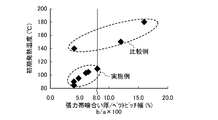
- FIG. 11 is a diagram illustrating the relationship between the ratio of the belt pitch width and the tension band meshing thickness and the change in belt tension (interaxial force) for the examples and comparative examples.
- FIG. 12 is a diagram showing the relationship between the ratio of the belt pitch width and the tension band meshing thickness and the high-speed durability for the examples and comparative examples.
- FIG. 13 is a diagram showing the relationship between the ratio of the belt pitch width and the tension band meshing thickness and the initial heat generation temperature for Examples and Comparative Examples.
- FIG. 14 is a diagram illustrating the relationship between the ratio of the belt pitch width and the tension band meshing thickness and the tightening allowance for the examples and comparative examples.
- FIG. 15 is a diagram illustrating the relationship between the ratio of the belt pitch width and the tension band meshing thickness and the transmission torque at the time of 2% slip for the example and the comparative example.
- FIG. 16 is a diagram illustrating the relationship between the ratio of the belt pitch width and the tension band meshing thickness and the belt efficiency in Examples and Comparative Examples.
- FIG. 17 is a diagram illustrating the relationship between the ratio of the belt pitch width and the tension band engagement thickness, the tension band engagement thickness, and the total thickness with respect to the change in belt tension (interaxial force).
- FIG. 18 is a diagram showing the relationship between the ratio of the belt pitch width and the tension band meshing thickness and the tension band meshing thickness and the total thickness with respect to the change in the tightening allowance.
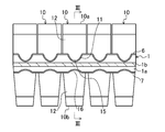
- FIG. 1 to 3 show a high load transmission V-belt B according to an embodiment of the present invention.
- this belt B is used by being wound around a plurality of transmission pulleys of a belt type continuously variable transmission, for example.
- the belt B is composed of a pair of left and right endless tension bands 1, 1 and a number of blocks 10, 10,... That are continuously locked and fixed to the tension bands 1, 1 in the belt length direction.
- each of the tension bands 1 includes a plurality of core wires 1 b, 1 b,... (Core body) having high strength and high elastic modulus such as aramid fibers inside a shape-retaining rubber layer 1 a made of hard rubber. Are embedded in a spiral shape.
- the upper surface of each tension band 1 has groove-shaped upper concave portions 2, 2,... As upper meshed portions extending in the belt width direction corresponding to the respective blocks 10, and the upper concave portion 2 on the lower surface. , 2,... Are formed as lower meshing portions 3, 3,.
- the portion between the upper recesses 2, 2,... Is in the upper cog portion 4, and the portion between the lower recesses 3, 3,. Each is composed.
- the hard rubber forming the shape retaining rubber layer 1a is excellent in heat resistance and permanently deformed by, for example, reinforcing H-NBR rubber reinforced with zinc methacrylate with short fibers such as aramid fiber and nylon fiber. Hard rubber that is difficult is used.
- the hardness of this hard rubber requires a rubber hardness of 75 ° or more when measured with a JIS-C hardness meter.
- the upper and lower canvas layers 6 and 7 are formed on the upper and lower surfaces of the tension band 1 by integrally bonding canvases treated with glue rubber, respectively.
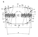
- each block 10 has a notch slit-like fitting portion 11 for fitting each tension band 1 detachably from the width direction on the left and right side portions in the belt width direction. , 11.
- the left and right side surfaces excluding the fitting portion 11 are configured as contact portions 12 and 12 that contact a pulley groove surface (not shown) such as a transmission pulley.
- the belt angle ⁇ formed by the left and right contact portions 12, 12 of the block 10 is the same as the angle of the pulley groove surface.
- the block 10 is composed of upper and lower beam portions 10a and 10b extending in the belt width direction (left and right direction), and a pillar portion 10c that vertically connects the left and right central portions of the beam portions 10a and 10b. It is formed in an H shape.
- the tension bands 1, 1 are press-fitted into the fitting portions 11, 11 between the upper and lower beam portions 10 a, 10 b of each block 10, so that the blocks 10, 10,. It is continuously fixed in the vertical direction.
- the upper convex portion 15 made of a ridge as an upper meshing portion meshing with each upper concave portion 2 on the upper surface of the tension band 1 is formed on the upper wall surface of each fitting portion 11 in each block 10.
- lower convex portions 16 formed of convex strips as lower meshing portions meshing with the respective lower concave portions 3 on the lower surface of the tension band 1 are formed in parallel with each other. ing.
- the contact portion 12 (the outer side surface of each tension band 1 may be in contact with each other) that is the side surface of each block 10 contacts the pulley groove surface, and the upper and lower convex portions 15 and 16 of the block 10.
- the (meshing portion) and the upper and lower concave portions 2 and 3 (meshed portions) of each tension band 1 are engaged with each other, power is exchanged with the pulley.
- each of the blocks 10 includes a reinforcing material 18 such as a lightweight aluminum alloy, which is a higher elastic modulus material, in a hard resin such as a phenol resin reinforced with short carbon fibers. It is assumed that it is embedded so as to be located in the center.
- the block 10 is constituted by a hard resin portion that forms the peripheral portion of the fitting portion 11 and the contact portions 12 and 12 and a reinforcing member 18 that forms the remaining portion.
- the reinforcing member 18 may be prevented from appearing on the surface of the block 10 at the peripheral portion of the fitting portion 11 and the contact portions 12 and 12 on the left and right side surfaces (sliding contact portions with the pulley groove surface). In this part, the surface of the block 10 may be exposed.
- the distance between the bottom surface of the lower recess 3 corresponding to the upper recess 2 (the lower surface of the lower canvas layer 7) is the block engagement thickness d, which is the engagement gap of the block 10, that is, as shown in FIG.
- the distance between the lower end of the upper convex portion 15 and the upper end of the lower convex portion 16 of each block 10 is set slightly larger (b> d).
- the belt pitch width which is the belt width at the position of the core wire 1b of the tension band 1
- b / a 0.08 (1)
- the tension band meshing thickness b is 8% or less of the belt pitch width a.
- b / a 0.04 to 0.08.
- the total tension band is the thickness of the upper and lower side cog parts 4 and 5 excluding the upper concave part 2 and the lower concave part 3 (upper and lower meshed parts).
- the belt pitch width a is related to the holding area where the tension band 1 holds the block 10 depending on the length thereof. Therefore, it is essential not only to reduce the tension band engagement thickness b, but also to associate the tension band engagement thickness b and the belt pitch width a as in the above formula (1) or (2).
- 1 to 5 may not accurately describe the relationship between the belt pitch width a, the tension band meshing thickness b, the tension band total thickness c, and the block meshing thickness d.
- the belt pitch width a and the tension band engagement thickness b of the high load transmission V-belt B are b / a ⁇ 0.08 (the tension band engagement thickness b is the belt pitch width a). 8% or less), the tension band meshing thickness b is sufficiently smaller than the belt pitch width a, and the tension band 1 is thinned. Therefore, when this belt B is run around the transmission pulley of the continuously variable transmission, the upper beam portion 10a of the block 10 is pushed up by the thermal expansion of the tension band 1, and the upper and lower beam portions 10a, 10b are expanded. Even if the running time of the belt B elapses, a change in the thrust / tension conversion ratio and a change in the belt tension associated therewith are suppressed.
- the thrust of the drive unit for driving the transmission pulley of the transmission to open and close and changing the gear ratio force for thrusting the movable sheave of the transmission pulley in the axial direction
- the thrust of the drive unit for driving the transmission pulley of the transmission to open and close and changing the gear ratio can be set low, suppressing the initial heat generation of the belt B, high efficiency And durability can be improved.
- the belt pitch width a and the tension band engagement thickness b are in a relationship of b / a ⁇ 0.05 (the tension band engagement thickness b is 5% or less of the belt pitch width a), the belt B travels. Changes in the thrust / tension conversion ratio over time can be further effectively suppressed.
- the tension band 1 becomes thin, and the upper concave portion 2 and the upper convex portion 15 of the block 10
- the holding force of the block 10 due to the engagement and the engagement between the lower concave portion 3 and the lower convex portion 16 of the block 10 is reduced.
- the total tension band thickness c between the cog parts 4 and 5 on the upper and lower surfaces of the tension band 1 is in the relationship of meshing thickness b and c / b ⁇ 2.0, and the tension at the cog parts 4 and 5 is Since the total band thickness c is increased, the block 10 is also supported by the cog portions 4 and 5 having a larger thickness than the tension band 1. As a result, the holding force of the tension band 1 on the block 10 does not decrease, and the swinging can be reliably suppressed.
- the reinforcing material 18 is inserted into each block 10.
- the reinforcing material 18 may be used and a block made of resin may be used. The effect is obtained.
- the high load transmission V-belt B is not only used by being wound around a transmission pulley of a belt type continuously variable transmission, but also a belt transmission having a constant speed pulley (V pulley). It can also be used in devices.
- Each block used was formed by inserting a reinforcing material made of a lightweight high-strength aluminum alloy having a thickness of 2 mm into a phenol resin. The same effect can be obtained even if the block is made entirely of resin without using the reinforcing material made of the aluminum alloy.
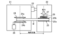
- the driving pulley 24 is drivingly connected to the driving motor 26, and a DC motor for loading (not shown) is also drivingly connected to the driven pulley 25 so that a constant load torque of 60 N ⁇ m is applied.
- the high load transmission V-belt B of each embodiment and each comparative example is wound between the drive and driven pulleys 24 and 25, the speed ratio is fixed to 1.8, and the movable sheave 25b of the driven pulley 25 is fixed.
- an axial thrust toward the fixed sheave 25 a was applied by the torque cam 27 and the spring 28. In this state, the drive pulley 24 was rotated at a constant rotational speed of 3000 rpm by the drive motor 26 to run the belt B.
- the axial force detected by the load cell 23 during the running is measured as the belt tension, and the initial value of the running of the belt B (after 0 to 24 hours from the start of running), the middle (after 24 to 48 hours after the start of running), and the measured value are Changes in the belt tension with time were confirmed from the measured values after the stable middle period (after 48 hours from the start of running).
- the temperature of the belt B was 120 ° C. The results are shown in FIGS. 9 to 11 and FIG.
- the belt tension change width is 100 N or less, and the change with time is small.
- the tension band meshing thickness b is 8% or less of the belt pitch width a
- the belt tension change width is 0 N, and there is no change over time.
- the tension band meshing thickness b exceeds 8% of the belt pitch width a, and thus the variation width is large.
- the tension band meshing thickness b is 4% (8% or less) of the belt pitch width a, but the change width is as large as 900N.
- Examples 1 to 6 in which the tension band engagement thickness b is 8% or less of the belt pitch width a and the tension band total thickness c is more than twice the tension band engagement thickness b are high-speed durability and initial heat generation characteristics.
- the change in the fastening allowance, the transmission capability, and the belt efficiency are also dramatically improved, and there are significant differences compared to Comparative Examples 1 to 3.
- the present invention is a high load transmission V-belt in which a resin block is locked and fixed to a tension band containing rubber, and there is little change with time in tension during belt running, and each performance of heat generation, running durability and belt efficiency is achieved. Since it is significantly higher than conventional ones, it is extremely useful and has high industrial applicability.
- Tension band 1 A Shape-retaining rubber layer 1b Core wire 2 Upper concave portion (upper meshed portion) 3 Lower concave part (lower meshed part) 4 Upper cog part 5 Lower cog part 10 Block 10a Upper beam part 10b Lower beam part 11 Fitting part 12 Contact part 15 Upper convex part (upper meshing part) 16 Lower convex part (lower meshing part) a Belt pitch width b Tension band meshing thickness c Total tension band thickness
Abstract
Priority Applications (5)
| Application Number | Priority Date | Filing Date | Title |
|---|---|---|---|
| JP2014506035A JP6122838B2 (ja) | 2012-03-19 | 2013-03-18 | 高負荷伝動用vベルト |
| DE112013001552.8T DE112013001552T5 (de) | 2012-03-19 | 2013-03-18 | Keilriemen für hohe Lastübertragung |
| CN201380014529.2A CN104246289B (zh) | 2012-03-19 | 2013-03-18 | 高负荷传动用v型带 |
| US14/486,839 US20150005121A1 (en) | 2012-03-19 | 2014-09-15 | V-belt for high load transmission |
| IN8492DEN2014 IN2014DN08492A (fr) | 2012-03-19 | 2014-10-10 |
Applications Claiming Priority (2)
| Application Number | Priority Date | Filing Date | Title |
|---|---|---|---|
| JP2012061605 | 2012-03-19 | ||
| JP2012-061605 | 2012-03-19 |
Related Child Applications (1)
| Application Number | Title | Priority Date | Filing Date |
|---|---|---|---|
| US14/486,839 Continuation US20150005121A1 (en) | 2012-03-19 | 2014-09-15 | V-belt for high load transmission |
Publications (1)
| Publication Number | Publication Date |
|---|---|
| WO2013140783A1 true WO2013140783A1 (fr) | 2013-09-26 |
Family
ID=49222262
Family Applications (1)
| Application Number | Title | Priority Date | Filing Date |
|---|---|---|---|
| PCT/JP2013/001846 WO2013140783A1 (fr) | 2012-03-19 | 2013-03-18 | Courroie trapézoïdale permettant de transmettre de hautes charges |
Country Status (6)
| Country | Link |
|---|---|
| US (1) | US20150005121A1 (fr) |
| JP (1) | JP6122838B2 (fr) |
| CN (1) | CN104246289B (fr) |
| DE (1) | DE112013001552T5 (fr) |
| IN (1) | IN2014DN08492A (fr) |
| WO (1) | WO2013140783A1 (fr) |
Families Citing this family (1)
| Publication number | Priority date | Publication date | Assignee | Title |
|---|---|---|---|---|
| DE112013001542T5 (de) * | 2012-03-19 | 2015-03-05 | Bando Chemical Industries, Ltd. | Keilriemen für hohe Lastübertragung |
Citations (2)
| Publication number | Priority date | Publication date | Assignee | Title |
|---|---|---|---|---|
| JPH0577650U (ja) * | 1992-03-23 | 1993-10-22 | 愛知機械工業株式会社 | 無段変速機のvベルト |
| JP2005155682A (ja) * | 2003-11-20 | 2005-06-16 | Bando Chem Ind Ltd | 伝動ベルト帆布用処理液、伝動ベルト用帆布及び伝動ベルト |
Family Cites Families (16)
| Publication number | Priority date | Publication date | Assignee | Title |
|---|---|---|---|---|
| JPS61127948A (ja) * | 1984-12-22 | 1986-06-16 | Honda Motor Co Ltd | 伝動vベルト |
| EP0213627B1 (fr) * | 1985-09-04 | 1989-10-04 | Bando Chemical Industries, Ltd. | Courroie trapézoidale |
| US4861120A (en) * | 1987-05-14 | 1989-08-29 | Edwards, Harper, Mcnew & Company | Modular endless track drive system and methods of making, installing and repairing same |
| JPH0510396A (ja) * | 1990-11-09 | 1993-01-19 | Bando Chem Ind Ltd | 高負荷伝動用vベルト及びその製造方法 |
| JPH08303529A (ja) * | 1995-05-01 | 1996-11-19 | Bando Chem Ind Ltd | コグドvベルト |
| JP3044212B2 (ja) * | 1998-10-13 | 2000-05-22 | バンドー化学株式会社 | 高負荷伝動用vベルト |
| JP2992022B1 (ja) * | 1998-10-16 | 1999-12-20 | バンドー化学株式会社 | 高負荷伝動用vベルト |
| KR100500501B1 (ko) * | 2000-05-09 | 2005-07-14 | 더 게이츠 코포레이션 | 블록식 무단 변속기용 벨트 |
| DE10026877A1 (de) * | 2000-06-02 | 2001-12-06 | Contitech Antriebssysteme Gmbh | Keilriemen zur verlustarmen Leistungsübertragung |
| US7070529B2 (en) * | 2001-05-30 | 2006-07-04 | Mitsuboshi Belting Ltd. | Power transmission belt |
| DE10127092A1 (de) * | 2001-06-02 | 2002-12-05 | Contitech Antriebssysteme Gmbh | Schwingungsarmer Hybridkeilriemen |
| JP3496830B2 (ja) * | 2001-06-28 | 2004-02-16 | バンドー化学株式会社 | 高負荷伝動用vベルト |
| JP3907456B2 (ja) * | 2001-11-29 | 2007-04-18 | バンドー化学株式会社 | 高負荷伝動用vベルト |
| JP3780237B2 (ja) * | 2002-08-19 | 2006-05-31 | バンドー化学株式会社 | 高負荷伝動用vベルト |
| JP2004076875A (ja) * | 2002-08-20 | 2004-03-11 | Bando Chem Ind Ltd | 高負荷伝動用vベルト |
| JP2005069358A (ja) * | 2003-08-25 | 2005-03-17 | Bando Chem Ind Ltd | 摩擦伝動ベルト及びその製造方法 |
-
2013
- 2013-03-18 WO PCT/JP2013/001846 patent/WO2013140783A1/fr active Application Filing
- 2013-03-18 JP JP2014506035A patent/JP6122838B2/ja active Active
- 2013-03-18 DE DE112013001552.8T patent/DE112013001552T5/de not_active Withdrawn
- 2013-03-18 CN CN201380014529.2A patent/CN104246289B/zh not_active Expired - Fee Related
-
2014
- 2014-09-15 US US14/486,839 patent/US20150005121A1/en not_active Abandoned
- 2014-10-10 IN IN8492DEN2014 patent/IN2014DN08492A/en unknown
Patent Citations (2)
| Publication number | Priority date | Publication date | Assignee | Title |
|---|---|---|---|---|
| JPH0577650U (ja) * | 1992-03-23 | 1993-10-22 | 愛知機械工業株式会社 | 無段変速機のvベルト |
| JP2005155682A (ja) * | 2003-11-20 | 2005-06-16 | Bando Chem Ind Ltd | 伝動ベルト帆布用処理液、伝動ベルト用帆布及び伝動ベルト |
Also Published As
| Publication number | Publication date |
|---|---|
| CN104246289B (zh) | 2016-01-13 |
| IN2014DN08492A (fr) | 2015-05-08 |
| JP6122838B2 (ja) | 2017-04-26 |
| US20150005121A1 (en) | 2015-01-01 |
| CN104246289A (zh) | 2014-12-24 |
| JPWO2013140783A1 (ja) | 2015-08-03 |
| DE112013001552T5 (de) | 2015-02-19 |
Similar Documents
| Publication | Publication Date | Title |
|---|---|---|
| WO2010023893A1 (fr) | Dispositif de transmission de puissance à courroie et courroie de transmission de puissance utilisée pour celui-ci | |
| US20100004084A1 (en) | Variable speed belt | |
| JP2009115209A (ja) | 湿式ベルト伝動装置 | |
| US3151491A (en) | Belt and belt-pulley drive | |
| US9677643B2 (en) | Notched transmission belt | |
| JP6122838B2 (ja) | 高負荷伝動用vベルト | |
| US6293886B1 (en) | Heavy-duty power transmission V-belt | |
| US8740738B2 (en) | High load transmission V-belt | |
| JP6109148B2 (ja) | 高負荷伝動用vベルト | |
| JP5325889B2 (ja) | 高負荷伝動用vベルト | |
| JP4525204B2 (ja) | 伝動用無端ベルト | |
| JP5014196B2 (ja) | プーリ構造体、及び、これを用いた補機駆動システム | |
| JP4893562B2 (ja) | 動力伝達チェーンおよび動力伝達装置 | |
| JP4893561B2 (ja) | 動力伝達チェーンおよび動力伝達装置 | |
| JP2001159453A (ja) | ベルト式伝動装置 | |
| JP2004076875A (ja) | 高負荷伝動用vベルト | |
| JP5762894B2 (ja) | 伝動用ベルト | |
| JP2000120794A (ja) | 高負荷伝動用vベルト | |
| JP5017292B2 (ja) | コグドvベルト | |
| JP2005226669A (ja) | ベルト伝動装置 | |
| JP2002070992A (ja) | ベルト伝動装置 | |
| JP2003166597A (ja) | 高負荷伝動用vベルト | |
| JP2010060068A (ja) | ベルトシステムおよびベルトシステムの歯付きベルトとプーリ |
Legal Events
| Date | Code | Title | Description |
|---|---|---|---|
| 121 | Ep: the epo has been informed by wipo that ep was designated in this application |
Ref document number: 13764008 Country of ref document: EP Kind code of ref document: A1 |
|
| ENP | Entry into the national phase |
Ref document number: 2014506035 Country of ref document: JP Kind code of ref document: A |
|
| WWE | Wipo information: entry into national phase |
Ref document number: 1120130015528 Country of ref document: DE Ref document number: 112013001552 Country of ref document: DE |
|
| 122 | Ep: pct application non-entry in european phase |
Ref document number: 13764008 Country of ref document: EP Kind code of ref document: A1 |