WO2013111619A1 - センサ - Google Patents
センサ Download PDFInfo
- Publication number
- WO2013111619A1 WO2013111619A1 PCT/JP2013/050316 JP2013050316W WO2013111619A1 WO 2013111619 A1 WO2013111619 A1 WO 2013111619A1 JP 2013050316 W JP2013050316 W JP 2013050316W WO 2013111619 A1 WO2013111619 A1 WO 2013111619A1
- Authority
- WO
- WIPO (PCT)
- Prior art keywords
- case
- sensor element
- holder
- sensor
- resin
- Prior art date
- Legal status (The legal status is an assumption and is not a legal conclusion. Google has not performed a legal analysis and makes no representation as to the accuracy of the status listed.)
- Ceased
Links
Images


Classifications
-
- G—PHYSICS
- G01—MEASURING; TESTING
- G01B—MEASURING LENGTH, THICKNESS OR SIMILAR LINEAR DIMENSIONS; MEASURING ANGLES; MEASURING AREAS; MEASURING IRREGULARITIES OF SURFACES OR CONTOURS
- G01B7/00—Measuring arrangements characterised by the use of electric or magnetic techniques
- G01B7/003—Measuring arrangements characterised by the use of electric or magnetic techniques for measuring position, not involving coordinate determination
-
- G—PHYSICS
- G01—MEASURING; TESTING
- G01P—MEASURING LINEAR OR ANGULAR SPEED, ACCELERATION, DECELERATION, OR SHOCK; INDICATING PRESENCE, ABSENCE, OR DIRECTION, OF MOVEMENT
- G01P1/00—Details of instruments
- G01P1/02—Housings
- G01P1/026—Housings for speed measuring devices, e.g. pulse generator
-
- G—PHYSICS
- G01—MEASURING; TESTING
- G01D—MEASURING NOT SPECIALLY ADAPTED FOR A SPECIFIC VARIABLE; ARRANGEMENTS FOR MEASURING TWO OR MORE VARIABLES NOT COVERED IN A SINGLE OTHER SUBCLASS; TARIFF METERING APPARATUS; MEASURING OR TESTING NOT OTHERWISE PROVIDED FOR
- G01D11/00—Component parts of measuring arrangements not specially adapted for a specific variable
- G01D11/24—Housings ; Casings for instruments
- G01D11/245—Housings for sensors
-
- G—PHYSICS
- G01—MEASURING; TESTING
- G01P—MEASURING LINEAR OR ANGULAR SPEED, ACCELERATION, DECELERATION, OR SHOCK; INDICATING PRESENCE, ABSENCE, OR DIRECTION, OF MOVEMENT
- G01P1/00—Details of instruments
-
- G—PHYSICS
- G01—MEASURING; TESTING
- G01P—MEASURING LINEAR OR ANGULAR SPEED, ACCELERATION, DECELERATION, OR SHOCK; INDICATING PRESENCE, ABSENCE, OR DIRECTION, OF MOVEMENT
- G01P3/00—Measuring linear or angular speed; Measuring differences of linear or angular speeds
- G01P3/42—Devices characterised by the use of electric or magnetic means
- G01P3/44—Devices characterised by the use of electric or magnetic means for measuring angular speed
- G01P3/48—Devices characterised by the use of electric or magnetic means for measuring angular speed by measuring frequency of generated current or voltage
- G01P3/481—Devices characterised by the use of electric or magnetic means for measuring angular speed by measuring frequency of generated current or voltage of pulse signals
- G01P3/487—Devices characterised by the use of electric or magnetic means for measuring angular speed by measuring frequency of generated current or voltage of pulse signals delivered by rotating magnets
-
- G—PHYSICS
- G01—MEASURING; TESTING
- G01D—MEASURING NOT SPECIALLY ADAPTED FOR A SPECIFIC VARIABLE; ARRANGEMENTS FOR MEASURING TWO OR MORE VARIABLES NOT COVERED IN A SINGLE OTHER SUBCLASS; TARIFF METERING APPARATUS; MEASURING OR TESTING NOT OTHERWISE PROVIDED FOR
- G01D5/00—Mechanical means for transferring the output of a sensing member; Means for converting the output of a sensing member to another variable where the form or nature of the sensing member does not constrain the means for converting; Transducers not specially adapted for a specific variable
- G01D5/12—Mechanical means for transferring the output of a sensing member; Means for converting the output of a sensing member to another variable where the form or nature of the sensing member does not constrain the means for converting; Transducers not specially adapted for a specific variable using electric or magnetic means
- G01D5/244—Mechanical means for transferring the output of a sensing member; Means for converting the output of a sensing member to another variable where the form or nature of the sensing member does not constrain the means for converting; Transducers not specially adapted for a specific variable using electric or magnetic means influencing characteristics of pulses or pulse trains; generating pulses or pulse trains
- G01D5/245—Mechanical means for transferring the output of a sensing member; Means for converting the output of a sensing member to another variable where the form or nature of the sensing member does not constrain the means for converting; Transducers not specially adapted for a specific variable using electric or magnetic means influencing characteristics of pulses or pulse trains; generating pulses or pulse trains using a variable number of pulses in a train
- G01D5/2451—Incremental encoders
Definitions
- the present invention relates to a sensor in which a sensor element housed in a case is held in a positioned state.
- a rotation detection sensor used to detect a vehicle speed includes a sensor element which is formed of a resin or the like and housed in a case fixed to the vehicle side.
- the sensor element is attached to a detection target such as an inner ring of a bearing and disposed to face a detected portion that rotates integrally with the detection target.
- the sensor element detects the amount of magnetic flux that changes as the magnetized detection target rotates, thereby detecting the rotational speed of the axle. Therefore, in the rotation detection sensor, it is necessary to accurately position the sensor element with respect to the detected portion.
- the rotation detection sensor disclosed in Patent Document 1 is configured to include a fixing member, a holder (detection unit) including a sensor element (Hall IC), and a case that covers the sensor element (Hall IC).
- a detection surface is provided on the outer surface of the case, and a sensor element (Hall IC) is positioned on the back side of the detection surface by inserting a part of the holder into the inside of the case.
- the movement of the case in the longitudinal direction (proximal direction) is restricted at the time of resin molding of the fixing portion, thereby positioning the sensor element at a position facing the detected portion.
- the sensor element is inserted and disposed inside the case via the holder, and a space is usually present between the back surface of the detection surface and the sensor element.
- the sensor element be in close proximity to the back surface of the detection surface as much as possible.
- the sensor element can be pressed against the back surface of the detection surface by filling the case with a molding resin.
- the molding resin is filled in the case, the sensor element may be damaged by receiving stress or heat from the molding resin.
- the case is formed in a bag shape, the case itself may be inflated by filling the case with the molding resin, and the detection sensitivity of the sensor element may be unstable.
- An object of the present invention is to provide a sensor capable of holding a sensor element at a position with good detection sensitivity without filling the case with resin.
- a sensor element a case having the sensor element internally mounted, and a case having a detection surface of the sensor element on an outer surface, and the sensor element internally provided with the sensor element
- the sensor element is mounted in the case, and the sensor element is positioned by being pressed to the side of the detection surface of the case outer surface by the holder.
- the contact portion provided on at least one of the holder and the case is configured to be deformable by the pressing force when the sensor element is pressed toward the detection surface, the sensor element is a holder.
- the contact portion is deformed by the reaction force received from the detection surface when being pressed by the force sensor.
- the sensor element can be held in a state where the pressing force on the sensor element is appropriately reduced. As a result, the sensor element can be reliably positioned on the side of the detection surface without injecting resin into the housed case.
- a second characterizing feature of the sensor according to the present invention is that the case and the cable electrically connected to the sensor element are integrated by a molded part using a resin.
- the case and the cable electrically connected to the sensor element are integrated by a resin molded part, the posture of the case for housing the sensor element and the sensor element are electrically connected.
- the sensor's detection sensitivity can be maintained because the cable's posture is stable together.
- a third characterizing feature of the sensor according to the present invention is that the outer surface of the case and the cable is made of resin, and the case and the cable are adhered by melting the resin portion in contact with the molded portion. .
- the step of applying the adhesive material to the case and the cable is unnecessary.
- the sensor can be easily manufactured.
- a fourth characterizing feature of the sensor of the present invention is that the holder is provided with a lid that closes the insertion opening of the case.
- the lid prevents the resin from entering the case. Thereby, the influence of the pressure and heat of the molding resin on the sensor element can be suppressed. In addition, the resin intrusion into the case is prevented, so that the case in which the case in which the sensor element is accommodated is expanded by the resin is also prevented.
- the case is formed in a bag shape, and the sensor element and the holder are held between the opposed inner surfaces of the case.
- the holder presses the sensor element to the detection surface side only by inserting and arranging the sensor element and the holder in the case. Accordingly, alignment and position holding of the sensor element on the detection surface are facilitated.
- a sixth characterizing feature of the sensor of the present invention is that the contact portion is a convex portion extending along the insertion direction of the holder.
- the contact portion is a convex portion extending along the insertion direction of the holder
- the convex portion presses and guides the holder toward the detection surface when inserting the holder into the case. Work as it is. As a result, the holder can be easily inserted into the case.
- a seventh characterizing feature of the sensor of the present invention is that the contact portion is formed on the holder.
- the contact portion is formed on the inner surface of the case.
- the case in which the sensor element is disposed may be elongated in shape, and in such a case, it is difficult to form an abutment on the inner surface of the case.
- the contact portion is formed on the holder as in the present configuration, the contact portion is formed on the outer surface of the holder.
- the contact portion formed on the outer surface of the holder is a portion which can be formed by a mold when resin-molded, and it is possible to form a contact portion of various shapes. Therefore, the contact portion can be easily formed by forming the contact portion on the holder.
- the sensor according to the present invention is applied to, for example, a rotation detection sensor that detects the rotation state of a wheel of a vehicle or the like.
- the rotation detection sensor detects the rotational state of the wheel by detecting the amount of change in magnetic flux generated from the integrally mounted rotor attached to the axle as the detection target.
- the rotation detection sensor 1 is disposed opposite to the end face of the magnetizing rotor 3 disposed coaxially with the axle 2.
- the end face of the magnetizing rotor 3 is alternately magnetized in the circumferential direction with the N pole and the S pole.
- the rotation detection sensor 1 detects a change in the magnetic flux, whereby the rotational speed of the axle 2, that is, the speed of the vehicle is detected.
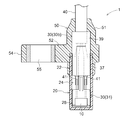
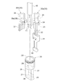
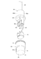
- the rotation detection sensor 1 includes a sensor element 10, a case 20 in which the sensor element 10 is installed, a holder 30 installed in the case 20 together with the sensor element 10, and a sensor element 10 and a cable 40 electrically connected to it.
- the case 20 has the detection surface 21 of the sensor element 10 on the outer surface.
- the holder 30 is arranged to press the sensor element 10 on the side of the detection surface 21.
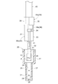
- the case 20 is formed in a sack shape, and includes a cylindrical portion 22 having a cylindrical outer shape and having openings at the top and bottom, and a sensor element housing portion 24 formed in a rectangular shape continuously provided below the cylindrical portion 22. ing.
- the sensor element housing 24 has a front surface 26 on which the detection surface 21 facing the magnetized rotor 3 is located, and a back surface 27 facing the front surface 26. At a lower portion of the back surface portion 27, a convex surface portion 29 projecting inward over the bottom portion 28 is provided. Therefore, in the sensor element housing portion 24, the narrowest region is between the front surface portion 26 and the convex surface portion 29 of the back surface portion 27.
- the holder 30 is formed to extend in a substantially rod-like shape, and a Hall IC as a sensor element 10 that holds a signal according to a change in the magnetic flux generated by the rotation of the magnetized rotor 3 is held at the tip end side.
- the holder 30 is inserted into the case 20 such that the Hall IC 10 is accommodated in the case 20 at the tip end portion.
- the case 20, the holder 30, and the cable 40 are covered with a resin molded part 50.
- the molded portion 50 includes a main covering portion 51 covering the case 20, the holder 30, and the cable 40, and a fixed support portion 52 attached to a vehicle or the like.
- the main cover 51 and the fixed support 52 are integrally formed of resin such as plastic.
- the fixed support portion 52 is formed so as to protrude outward in the circumferential direction of the main covering portion 51 located on the outer periphery of the holder 30, and is bolted so as to extend along one direction perpendicular to the radial direction of the main covering portion 51
- a unit 54 is provided.
- the bolt fixing portion 54 is formed with a through hole 55 through which a fixing member (for example, a bolt) (not shown) for fixing the rotation detection sensor 1 to the outer ring 3b is inserted.
- the case 20 and the holder 30 are reliably positioned by attaching the fixed support 52 to a vehicle or the like.
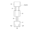
- the holder 30 has a first holder portion 30 a and a second holder portion 30 b.
- the first holder portion 30a includes a sensor holding portion 31 for holding the Hall IC 10, a half first wire holding portion 33 for holding the wire 41 of the cable 40, and a first half cable holding portion for holding the cable 40. 35 and equipped with.
- a first connection portion 32 is provided between the sensor holding portion 31 and the first wire holding portion 33, and a second connection portion 34 is provided between the first wire holding portion 33 and the first cable holding portion 35. Is provided.
- the wire 41 of the cable 40 is electrically connected to the Hall IC 10.
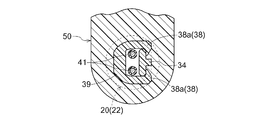
- a deformable abutment portion 36 is provided on the outer surface of the sensor holding portion 31 at a position facing the back surface portion 27 of the case 20.
- the contact portion 36 provided on the holder 30 is a convex portion extended and formed along the insertion direction of the holder 30 into the case 20.
- the convex portion (contact portion) 36 acts so as to guide the holder 30 while pressing the holder 30 to the detection surface 21 side. This facilitates the insertion of the holder 30 into the case 20.
- the second holder portion 30 b includes a half second wire holding portion 37 and a half second cable holding portion 39. Between the second wire holding portion 37 and the second cable holding portion 39, there is provided a third connection portion 38 having claw portions 38a, 38a formed to protrude toward the second connection portion 34.
- the holder 30 is configured by snap-fitting the claws 38 a and 38 a to the second connection portion 34 of the first holder 30 a, and the wire 41 is held by the holder 30.
- the sensor holding portion 31 of the holder 30 is inserted and arranged in the case 20 in a state where the sensor element 10 is mounted on the sensor holding portion 31 of the first holder portion 30 a Configured
- the sensor element 10 is pressed by the holder 30 toward the detection surface 21 (the outer surface of the front surface 26) of the case 20 and positioned.
- the width A of the end of the sensor holding portion 31 to which the sensor element 10 is attached is larger than the width B of the portion of the end of the case 20 where the sensor element 10 is disposed. Therefore, when the holder 30 is inserted into the case 20, the convex portion 29 formed on the back surface 27 and the contact portion 36 of the holder 30 are in contact with each other.
- the contact portion 36 is configured to be deformable by a pressing force when the sensor element 10 is pressed toward the detection surface 21. Therefore, the contact portion 36 is deformed by the reaction force received from the detection surface 21 when the sensor element 10 is pressed by the holder 30. As described above, the deformation of the contact portion 36 can hold the sensor element 10 on the detection surface 21 while appropriately reducing the pressure on the sensor element 10. As a result, the sensor element 10 can be reliably positioned on the side of the detection surface 21 without injecting resin into the housed case 20.
- the insertion opening of the case 20 is a cylindrical portion of the holder 30, the wire holding portions 33 and 37 and the connection portion 34, Blocked by 38. That is, the holder 30 is provided with wire holding portions 33 and 39 and connection portions 34 and 38 as lids for closing the insertion opening of the case 20.
- the case 20, the holder 30, and the cable 40 are disposed in a mold, and a resin is poured into the mold to form the molded portion 50. Since the holder 30 is provided with lids (wire holding portions 33 and 37 and connection portions 34 and 38) for closing the insertion opening of the case 20, the lid (wire holding portion) can be molded when the molded portion 50 is resin-molded. The portions 33 and 37 and the connection portions 34 and 38) prevent the resin from entering the case 20. Thereby, the influence of the pressure and the heat of the molding resin on the sensor element 10 can be suppressed. In addition, since the intrusion of the resin into the case 20 is prevented, the problem that the sensor element accommodating portion 24 of the case 20 is expanded by the resin is also prevented.
- the outer surfaces of the case 20 and the cable 40 are made of resin.
- the molded part 50 is resin-molded, the case 20 and the cable 40 and the molded part 50 are bonded by melting the resin parts that are in contact with each other. As a result, the process of applying the adhesive material to the case 20 and the cable 40 becomes unnecessary, and the sensor 1 can be manufactured easily.
- the case 20 is formed in a bag shape, and the sensor element 10 and the holder 30 are held between the opposed inner surfaces (the front portion 26 and the back portion 27) of the sensor element receiving portion 24 of the case 20. Therefore, the holder 30 presses the sensor element 10 toward the detection surface 21 only by inserting and arranging the sensor element 10 and the holder 30 in the sensor element housing 24. As a result, alignment and holding of the sensor element 10 on the detection surface 21 can be facilitated.
- the sensor element 10 is disposed at the bottom 28 of the case 20.
- the rotation detection sensor 1 is disposed to face, for example, a gear member (magnetic metal material or the like) that rotates in conjunction with an output side of a vehicle wheel, an engine, a transmission, or the like.
- a gear member magnetic metal material or the like
- the sensor element 10 detects a change in the magnetic field of the gear member at the time of driving the vehicle, it is possible to detect, for example, the speed of the wheel and the number of rotations of the engine, transmission, and the like.
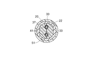
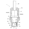
- the rotation detection sensor 1 includes a sensor element 10, a case 20 in which the sensor element 10 is installed, a holder 60 installed in the case 20 together with the sensor element 10, and a cable 40 electrically connected to the sensor element 10.
- the case 20 has the detection surface 21 of the sensor element 10 on the outer surface.
- the holder 60 is arranged to press the sensor element 10 on the detection surface 21 side.
- the case 20 has a cylindrical outer shape, and is constituted by a cylindrical portion 22 having an opening at the top and bottom and a bottomed sensor element housing portion 24 continuously provided below.
- the sensor element housing portion 24 has a cylindrical outer shape, and is formed with a flat portion 24 a chamfered on the outer peripheral surface.
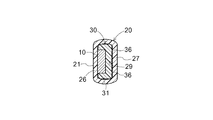
- the detection surface 21 of the sensor element 10 is provided at the bottom 28 of the case 20.
- the holder 60 is configured by joining a first half holder portion 60a and a second half holder portion 60b, and a flange portion 61 is provided at an intermediate position in the longitudinal direction.
- the first leg 62 and the second leg 63 for holding the sensor element 10 are disposed opposite to each other.
- a contact portion 64 that can be deformed to abut the sensor element 10 at a position between the first leg portion 62 and the second leg portion 63 of the holder 60 is provided, and the contact portion 64 is formed in a cross shape. It projects towards the sensor element 10.
- the sensor element 10 is mounted on the holder 60 by holding the sensor element 10 between the first leg 62 and the second leg 63 of the holder 60. Thereafter, by inserting the tip end side of the holder 60 into the case 20, the sensor element 10 is inserted into the case 20 and disposed. The sensor element 10 is pressed toward the detection surface 21 of the bottom portion 28 of the case 20 with the sensor element 10 in contact with the contact portion 64 by the holder 60. The contact portion 64 is deformed by a reaction force received from the detection surface 21 when the sensor element 10 is pressed by the holder 60. By deforming the contact portion 64, the sensor element 10 is held in contact with the detection surface 21 in a state where the pressing force on the sensor element 10 is appropriately reduced.
- the first leg 62 and the second leg 63 of the holder 60 holding the sensor element 10 are configured to be in contact with opposing positions on the inner surface of the case 20.
- the outer surface of the second leg 63 is formed with a deformable protrusion 66 extending along the insertion direction of the holder 60 into the case 20.
- the convex portion 66 serves to guide the holder 60. Further, rattling of the sensor element 10 in the horizontal direction (direction parallel to the detection surface 21) in the case 20 is also suppressed by the first leg portion 62 and the second leg portion 63.
- the contact portion 36 is formed on the outer surface of the holder 30, but the contact portion 36 may be formed on the inner surface of the case 20. However, when the contact portion 36 is formed on the case 20, the contact portion 36 is formed on the inner surface of the case 20.
- the case 20 in which the sensor element 10 is disposed may have an elongated shape, and in such a case, it is difficult to form the contact portion 36 on the inner surface of the case 20.
- the contact portion 36 formed on the outer surface of the holder 30 is a portion which can be formed by a mold when resin-molded, and the contact portion 36 having various shapes can be formed.
- the contact portion 64 of the holder 60 facing the sensor element 10 is formed in a cross shape, but even if the contact portion 64 is formed in a planar shape Good.
- the sensor according to the present invention can be widely used for various sensors.
Landscapes
- Physics & Mathematics (AREA)
- General Physics & Mathematics (AREA)
- Transmission And Conversion Of Sensor Element Output (AREA)
- Measuring Fluid Pressure (AREA)
Priority Applications (3)
| Application Number | Priority Date | Filing Date | Title |
|---|---|---|---|
| BR112014016224A BR112014016224A8 (pt) | 2012-01-23 | 2013-01-10 | sensor |
| CN201390000219.0U CN204115745U (zh) | 2012-01-23 | 2013-01-10 | 传感器 |
| US14/360,478 US9618315B2 (en) | 2012-01-23 | 2013-01-10 | Sensor |
Applications Claiming Priority (2)
| Application Number | Priority Date | Filing Date | Title |
|---|---|---|---|
| JP2012-011369 | 2012-01-23 | ||
| JP2012011369A JP6015008B2 (ja) | 2012-01-23 | 2012-01-23 | センサ |
Publications (1)
| Publication Number | Publication Date |
|---|---|
| WO2013111619A1 true WO2013111619A1 (ja) | 2013-08-01 |
Family
ID=48873341
Family Applications (1)
| Application Number | Title | Priority Date | Filing Date |
|---|---|---|---|
| PCT/JP2013/050316 Ceased WO2013111619A1 (ja) | 2012-01-23 | 2013-01-10 | センサ |
Country Status (5)
| Country | Link |
|---|---|
| US (1) | US9618315B2 (enExample) |
| JP (1) | JP6015008B2 (enExample) |
| CN (1) | CN204115745U (enExample) |
| BR (1) | BR112014016224A8 (enExample) |
| WO (1) | WO2013111619A1 (enExample) |
Cited By (3)
| Publication number | Priority date | Publication date | Assignee | Title |
|---|---|---|---|---|
| DE102014013312A1 (de) * | 2014-09-08 | 2016-03-10 | Wabco Gmbh | Träger für ein Sensorelement, Bauteilgruppe und Drehzahlsensor |
| JP2017526917A (ja) * | 2014-09-08 | 2017-09-14 | ヴアブコ・ゲゼルシヤフト・ミツト・ベシユレンクテル・ハフツングWABCO GmbH | センサ素子のための保持体、部品集合体及び回転数センサ |
| JP2021156730A (ja) * | 2020-03-27 | 2021-10-07 | 日立金属株式会社 | 温度検出装置及び配線部品 |
Families Citing this family (4)
| Publication number | Priority date | Publication date | Assignee | Title |
|---|---|---|---|---|
| CN103528824B (zh) * | 2013-10-31 | 2015-09-30 | 华中科技大学 | 基于弹性基础的内外双转子故障模拟实验台 |
| JP6403088B2 (ja) * | 2014-06-17 | 2018-10-10 | 日立金属株式会社 | モールド樹脂付きケーブル |
| JP6281461B2 (ja) * | 2014-09-30 | 2018-02-21 | 日立金属株式会社 | 樹脂モールド付きケーブルの製造方法 |
| JP6838306B2 (ja) * | 2016-07-08 | 2021-03-03 | 日立金属株式会社 | 車載用検出装置 |
Citations (5)
| Publication number | Priority date | Publication date | Assignee | Title |
|---|---|---|---|---|
| JPH11295331A (ja) * | 1998-04-10 | 1999-10-29 | Matsushita Electric Ind Co Ltd | 回転数センサあるいは回転角度センサ |
| JP2000164267A (ja) * | 1998-11-27 | 2000-06-16 | Ins:Kk | ケーブル接続部形成方法 |
| JP2003198093A (ja) * | 2001-12-21 | 2003-07-11 | Aisin Seiki Co Ltd | 電子回路 |
| JP2005227095A (ja) * | 2004-02-12 | 2005-08-25 | Sumiden Electronics Kk | 磁気変量センサ |
| JP2007121109A (ja) * | 2005-10-27 | 2007-05-17 | Aisin Seiki Co Ltd | センサ装置 |
Family Cites Families (8)
| Publication number | Priority date | Publication date | Assignee | Title |
|---|---|---|---|---|
| JP3056674B2 (ja) * | 1995-10-12 | 2000-06-26 | 株式会社三協精機製作所 | 回転検出装置 |
| JPH11120830A (ja) * | 1997-10-09 | 1999-04-30 | Hitachi Ltd | 平形多芯ケーブル接続構造 |
| JP2004264213A (ja) | 2003-03-03 | 2004-09-24 | Hitachi Unisia Automotive Ltd | 回転検出装置 |
| JP5146711B2 (ja) | 2003-05-29 | 2013-02-20 | アイシン精機株式会社 | 樹脂封止品製造方法及びケース |
| EP1718937B1 (de) | 2004-02-24 | 2012-06-13 | Prettl, Rolf | Sensorhalter und verfahren zu dessen herstellung |
| JP4543751B2 (ja) | 2004-05-27 | 2010-09-15 | アイシン精機株式会社 | 回転センサ |
| JP4661236B2 (ja) | 2005-01-28 | 2011-03-30 | アイシン精機株式会社 | 回転検出センサ |
| JP4640590B2 (ja) * | 2005-05-30 | 2011-03-02 | アイシン精機株式会社 | センサ装置 |
-
2012
- 2012-01-23 JP JP2012011369A patent/JP6015008B2/ja not_active Expired - Fee Related
-
2013
- 2013-01-10 US US14/360,478 patent/US9618315B2/en active Active
- 2013-01-10 CN CN201390000219.0U patent/CN204115745U/zh not_active Expired - Lifetime
- 2013-01-10 WO PCT/JP2013/050316 patent/WO2013111619A1/ja not_active Ceased
- 2013-01-10 BR BR112014016224A patent/BR112014016224A8/pt active Search and Examination
Patent Citations (5)
| Publication number | Priority date | Publication date | Assignee | Title |
|---|---|---|---|---|
| JPH11295331A (ja) * | 1998-04-10 | 1999-10-29 | Matsushita Electric Ind Co Ltd | 回転数センサあるいは回転角度センサ |
| JP2000164267A (ja) * | 1998-11-27 | 2000-06-16 | Ins:Kk | ケーブル接続部形成方法 |
| JP2003198093A (ja) * | 2001-12-21 | 2003-07-11 | Aisin Seiki Co Ltd | 電子回路 |
| JP2005227095A (ja) * | 2004-02-12 | 2005-08-25 | Sumiden Electronics Kk | 磁気変量センサ |
| JP2007121109A (ja) * | 2005-10-27 | 2007-05-17 | Aisin Seiki Co Ltd | センサ装置 |
Cited By (4)
| Publication number | Priority date | Publication date | Assignee | Title |
|---|---|---|---|---|
| DE102014013312A1 (de) * | 2014-09-08 | 2016-03-10 | Wabco Gmbh | Träger für ein Sensorelement, Bauteilgruppe und Drehzahlsensor |
| EP3192131A1 (de) * | 2014-09-08 | 2017-07-19 | WABCO GmbH | Träger für ein sensorelement, bauteilgruppe und drehzahlsensor |
| JP2017526917A (ja) * | 2014-09-08 | 2017-09-14 | ヴアブコ・ゲゼルシヤフト・ミツト・ベシユレンクテル・ハフツングWABCO GmbH | センサ素子のための保持体、部品集合体及び回転数センサ |
| JP2021156730A (ja) * | 2020-03-27 | 2021-10-07 | 日立金属株式会社 | 温度検出装置及び配線部品 |
Also Published As
| Publication number | Publication date |
|---|---|
| CN204115745U (zh) | 2015-01-21 |
| BR112014016224A2 (pt) | 2017-06-13 |
| JP6015008B2 (ja) | 2016-10-26 |
| US9618315B2 (en) | 2017-04-11 |
| JP2013148556A (ja) | 2013-08-01 |
| BR112014016224A8 (pt) | 2017-07-04 |
| US20140320113A1 (en) | 2014-10-30 |
Similar Documents
| Publication | Publication Date | Title |
|---|---|---|
| WO2013111619A1 (ja) | センサ | |
| JP2013148556A5 (enExample) | ||
| US9273947B2 (en) | Sensing magnet apparatus for motor | |
| CN104884962B (zh) | 轮速传感器及线束 | |
| EP3816599B1 (en) | Magnetic detection module, detection device, case assembly, and production method for magnetic detection module | |
| US8779759B2 (en) | Sensor device for detecting the rotational position of a rotating shaft | |
| US10209094B2 (en) | Rotation detection sensor and resin molding die for the sensor | |
| JP5491275B2 (ja) | 減速機付きモータ | |
| JP6673788B2 (ja) | 回転角検出装置 | |
| JP2011510310A (ja) | 磁界センサ | |
| EP1686381B1 (en) | Rotational speed detecting sensor | |
| US10101412B2 (en) | Sensing device and method for manufacturing sensing device | |
| US6903546B2 (en) | Rotation detection sensor | |
| US20110273854A1 (en) | Magnetic Field Sensor | |
| US10641623B2 (en) | Onboard detector including cable and sensor module including sensor, housing member and molded article | |
| CN107560532B (zh) | 行程传感器以及骑乘型车辆 | |
| EP3620754B1 (en) | A magnet holder and stroke sensor with the magnet holder | |
| EP1950570B1 (en) | Rotation detector | |
| EP4109064B1 (en) | Magnetic detection module, detection device, case assembly, and production method for magnetic detection module | |
| KR101770195B1 (ko) | 휠 속도 센서 | |
| JP7256974B2 (ja) | 移動体検出装置 | |
| JP2000171476A (ja) | 電磁ピックアップセンサおよびその製造方法 | |
| JP6969355B2 (ja) | 回転角度検出装置 | |
| JP6431466B2 (ja) | 回転検出装置 | |
| US11567098B2 (en) | Sensor assembly and method for producing a sensor assembly |
Legal Events
| Date | Code | Title | Description |
|---|---|---|---|
| WWE | Wipo information: entry into national phase |
Ref document number: 201390000219.0 Country of ref document: CN |
|
| 121 | Ep: the epo has been informed by wipo that ep was designated in this application |
Ref document number: 13741577 Country of ref document: EP Kind code of ref document: A1 |
|
| WWE | Wipo information: entry into national phase |
Ref document number: 14360478 Country of ref document: US |
|
| NENP | Non-entry into the national phase |
Ref country code: DE |
|
| REG | Reference to national code |
Ref country code: BR Ref legal event code: B01A Ref document number: 112014016224 Country of ref document: BR |
|
| 122 | Ep: pct application non-entry in european phase |
Ref document number: 13741577 Country of ref document: EP Kind code of ref document: A1 |
|
| ENP | Entry into the national phase |
Ref document number: 112014016224 Country of ref document: BR Kind code of ref document: A2 Effective date: 20140630 |