WO2013111256A1 - 二次電池 - Google Patents
二次電池 Download PDFInfo
- Publication number
- WO2013111256A1 WO2013111256A1 PCT/JP2012/051298 JP2012051298W WO2013111256A1 WO 2013111256 A1 WO2013111256 A1 WO 2013111256A1 JP 2012051298 W JP2012051298 W JP 2012051298W WO 2013111256 A1 WO2013111256 A1 WO 2013111256A1
- Authority
- WO
- WIPO (PCT)
- Prior art keywords
- battery
- electrode group
- insulating
- metal foil
- insulating sheet
- Prior art date
Links
Images


Classifications
-
- H—ELECTRICITY
- H01—ELECTRIC ELEMENTS
- H01M—PROCESSES OR MEANS, e.g. BATTERIES, FOR THE DIRECT CONVERSION OF CHEMICAL ENERGY INTO ELECTRICAL ENERGY
- H01M10/00—Secondary cells; Manufacture thereof
- H01M10/04—Construction or manufacture in general
- H01M10/0431—Cells with wound or folded electrodes
-
- H—ELECTRICITY
- H01—ELECTRIC ELEMENTS
- H01M—PROCESSES OR MEANS, e.g. BATTERIES, FOR THE DIRECT CONVERSION OF CHEMICAL ENERGY INTO ELECTRICAL ENERGY
- H01M50/00—Constructional details or processes of manufacture of the non-active parts of electrochemical cells other than fuel cells, e.g. hybrid cells
- H01M50/10—Primary casings, jackets or wrappings of a single cell or a single battery
- H01M50/116—Primary casings, jackets or wrappings of a single cell or a single battery characterised by the material
- H01M50/117—Inorganic material
- H01M50/119—Metals
-
- H—ELECTRICITY
- H01—ELECTRIC ELEMENTS
- H01M—PROCESSES OR MEANS, e.g. BATTERIES, FOR THE DIRECT CONVERSION OF CHEMICAL ENERGY INTO ELECTRICAL ENERGY
- H01M50/00—Constructional details or processes of manufacture of the non-active parts of electrochemical cells other than fuel cells, e.g. hybrid cells
- H01M50/10—Primary casings, jackets or wrappings of a single cell or a single battery
- H01M50/147—Lids or covers
- H01M50/155—Lids or covers characterised by the material
- H01M50/157—Inorganic material
- H01M50/159—Metals
-
- H—ELECTRICITY
- H01—ELECTRIC ELEMENTS
- H01M—PROCESSES OR MEANS, e.g. BATTERIES, FOR THE DIRECT CONVERSION OF CHEMICAL ENERGY INTO ELECTRICAL ENERGY
- H01M10/00—Secondary cells; Manufacture thereof
- H01M10/05—Accumulators with non-aqueous electrolyte
- H01M10/052—Li-accumulators
- H01M10/0525—Rocking-chair batteries, i.e. batteries with lithium insertion or intercalation in both electrodes; Lithium-ion batteries
-
- H—ELECTRICITY
- H01—ELECTRIC ELEMENTS
- H01M—PROCESSES OR MEANS, e.g. BATTERIES, FOR THE DIRECT CONVERSION OF CHEMICAL ENERGY INTO ELECTRICAL ENERGY
- H01M10/00—Secondary cells; Manufacture thereof
- H01M10/05—Accumulators with non-aqueous electrolyte
- H01M10/058—Construction or manufacture
- H01M10/0587—Construction or manufacture of accumulators having only wound construction elements, i.e. wound positive electrodes, wound negative electrodes and wound separators
-
- H—ELECTRICITY
- H01—ELECTRIC ELEMENTS
- H01M—PROCESSES OR MEANS, e.g. BATTERIES, FOR THE DIRECT CONVERSION OF CHEMICAL ENERGY INTO ELECTRICAL ENERGY
- H01M2220/00—Batteries for particular applications
- H01M2220/20—Batteries in motive systems, e.g. vehicle, ship, plane
-
- Y—GENERAL TAGGING OF NEW TECHNOLOGICAL DEVELOPMENTS; GENERAL TAGGING OF CROSS-SECTIONAL TECHNOLOGIES SPANNING OVER SEVERAL SECTIONS OF THE IPC; TECHNICAL SUBJECTS COVERED BY FORMER USPC CROSS-REFERENCE ART COLLECTIONS [XRACs] AND DIGESTS
- Y02—TECHNOLOGIES OR APPLICATIONS FOR MITIGATION OR ADAPTATION AGAINST CLIMATE CHANGE
- Y02E—REDUCTION OF GREENHOUSE GAS [GHG] EMISSIONS, RELATED TO ENERGY GENERATION, TRANSMISSION OR DISTRIBUTION
- Y02E60/00—Enabling technologies; Technologies with a potential or indirect contribution to GHG emissions mitigation
- Y02E60/10—Energy storage using batteries
-
- Y—GENERAL TAGGING OF NEW TECHNOLOGICAL DEVELOPMENTS; GENERAL TAGGING OF CROSS-SECTIONAL TECHNOLOGIES SPANNING OVER SEVERAL SECTIONS OF THE IPC; TECHNICAL SUBJECTS COVERED BY FORMER USPC CROSS-REFERENCE ART COLLECTIONS [XRACs] AND DIGESTS
- Y02—TECHNOLOGIES OR APPLICATIONS FOR MITIGATION OR ADAPTATION AGAINST CLIMATE CHANGE
- Y02P—CLIMATE CHANGE MITIGATION TECHNOLOGIES IN THE PRODUCTION OR PROCESSING OF GOODS
- Y02P70/00—Climate change mitigation technologies in the production process for final industrial or consumer products
- Y02P70/50—Manufacturing or production processes characterised by the final manufactured product
-
- Y—GENERAL TAGGING OF NEW TECHNOLOGICAL DEVELOPMENTS; GENERAL TAGGING OF CROSS-SECTIONAL TECHNOLOGIES SPANNING OVER SEVERAL SECTIONS OF THE IPC; TECHNICAL SUBJECTS COVERED BY FORMER USPC CROSS-REFERENCE ART COLLECTIONS [XRACs] AND DIGESTS
- Y02—TECHNOLOGIES OR APPLICATIONS FOR MITIGATION OR ADAPTATION AGAINST CLIMATE CHANGE
- Y02T—CLIMATE CHANGE MITIGATION TECHNOLOGIES RELATED TO TRANSPORTATION
- Y02T10/00—Road transport of goods or passengers
- Y02T10/60—Other road transportation technologies with climate change mitigation effect
- Y02T10/70—Energy storage systems for electromobility, e.g. batteries
Definitions
- the present invention relates to a secondary battery used for in-vehicle use.
- lithium ion secondary batteries with high energy density have been developed as power sources for electric vehicles and the like.
- external forces such as various impacts and loads may act on an electrode group housed in a battery can. Therefore, it is necessary to prevent a short circuit in the secondary battery.
- Patent Document 1 a technique of disposing a foldable insulating sheet between an electrode group and a battery can is disclosed.
- positioned so that a current collecting plate may be covered is disclosed (patent document 2).
- the outermost periphery of the electrode group is insulated with an insulating tape, the portion facing the inner surface of the outer can on the positive electrode lead and the positive electrode current collecting tab is covered with the first insulating cover, and the outer can of the negative electrode lead and the negative electrode current collecting tab is A technique of covering a portion facing the inner surface with a second insulating cover is also disclosed (Patent Document 3).
- the thickness of the insulating sheet is larger in consideration of the action of external force.
- the battery can has a preset size, the thickness of the insulating sheet If the thickness of the electrode is increased, the size of the electrode group needs to be reduced accordingly, and the battery capacity may be reduced.
- the region where the active material of the electrode group is coated is insulated from the battery can by the separator, but the separator has micropores, so Insulation may not be sufficient.
- the relationship between the thicknesses of the insulating tape and the first and second insulating covers is not defined.
- the present invention has been made in view of the above points, and an object thereof is a secondary battery capable of improving the insulation between the electrode group and the battery can against external force without reducing the battery capacity. Is to provide.
- the secondary battery of the present invention that solves the above problems is a wound electrode group obtained by winding an electrode in which a mixture layer is formed on a metal foil, a battery can that accommodates the wound electrode group, a wound electrode group, A secondary battery having an insulator interposed between the battery can, and the insulator is a mixture layer stack region formed at the center of the winding electrode group in the winding axis direction and the battery can.
- the portion interposed between the pair of exposed metal foil portions formed on both sides in the winding axis direction of the wound electrode group and the battery can is thicker than the portion interposed therebetween. It is said.
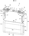
- FIG. 1 is an external perspective view of a secondary battery according to a first embodiment.
- the exploded perspective view of a secondary battery The exploded perspective view of a battery lid assembly and a winding electrode group.
- the external appearance perspective view which shows the state which expand
- FIG. 6 is an exploded perspective view of FIG. 5.
- FIG. 6 is an exploded perspective view of FIG. 5.
- FIG. 1 is an external perspective view of a secondary battery according to the present embodiment
- FIG. 2 is an exploded perspective view thereof
- FIG. 3 is an exploded perspective view of a battery lid assembly and a wound electrode group.
- a wound electrode group (power generation element) 40 is accommodated in a thin, substantially rectangular parallelepiped battery container 2 composed of a battery lid 3 and a battery can 4.
- the liquid is injected and configured.
- the battery lid 3 and the battery can 4 are formed of a conductive metal material such as aluminum, iron, and stainless steel, for example.
- the battery lid 3 is integrally assembled with a positive electrode current collector plate 21, a negative electrode current collector plate 31, and the like to constitute a battery lid unit 10.
- the positive electrode current collecting plate 21 and the negative electrode current collecting plate 31 of the battery lid unit 10 are respectively joined to the positive electrode metal foil or the negative electrode metal foil of the electrode group 40 by, for example, ultrasonic welding, so that the battery lid / power generation element 50 and is accommodated from the opening at the upper end of the battery can 4.
- the wound electrode group 40 is insulated by the insulating sheet 5 so as not to directly touch the battery can 4 by being covered with the insulating sheet 5, and is accommodated in the battery can 4. ing.
- the configuration of the insulating sheet 5 will be described later in detail.
- the battery lid 3 is provided with a liquid injection port 3a for injecting a non-aqueous electrolyte and a safety valve 13 for releasing the pressure when the internal pressure rises above a reference value due to overcharging or the like. .
- the liquid injection port 3a is closed by laser welding after the liquid injection stopper 11 is fitted after the injection of the electrolytic solution.
- the battery lid 3 is joined to the battery can 4 by laser welding and sealed.
- lithium hexafluorophosphate LiPF 6
- ethylene carbonate and dimethyl carbonate are mixed at a volume ratio of 1: 2.
- FIG. 4 is an external perspective view showing a state in which the winding end side of the electrode group 40 is developed.
- the wound electrode group 40 is formed by winding a positive electrode 41 and a negative electrode 42 in a flat shape around a shaft core (not shown) with the first and second separators 43 and 44 interposed therebetween.
- Reference numeral 40 a is a hollow portion having a width corresponding to the thickness of the axis of the wound electrode group 40.
- the wound electrode group 40 includes a flat surface portion 40b and a pair of curved portions 40c formed continuously on both sides of the flat surface portion 40b.
- the positive electrode 41 is obtained by forming a positive electrode mixture layer 41b on both front and back surfaces of a positive metal foil 41a made of, for example, aluminum foil.
- the positive electrode mixture layer 41b is coated with the positive electrode metal foil 41a so that a positive electrode metal foil exposed portion (positive electrode mixture untreated portion) 41c with the positive electrode metal foil 41a exposed on one side edge is formed. To be formed.
- the negative electrode 42 is obtained by coating a negative electrode mixture layer 42b on both front and back surfaces of a negative electrode metal foil 42a made of, for example, copper foil.
- the negative electrode mixture layer 42b is a negative electrode metal foil exposed portion (negative electrode mixture untreated) where the negative electrode metal foil 42a is exposed on the other side edge that is the side edge opposite to the side edge where the positive electrode metal foil exposed portion 41c is disposed.
- Part) 42c is formed by coating the negative electrode metal foil 42a with the positive electrode mixture.
- the positive electrode mixture layer 41b is composed of 10 parts by weight of scaly graphite as a conductive material and 10 parts by weight of polyvinylidene fluoride (binder) as a conductive material with respect to 100 parts by weight of lithium manganate (chemical formula LiMn 2 O 4 ) as a positive electrode active material.
- PVDF polyvinylidene fluoride
- NMP N-methyl pyrrolidone
- This positive electrode mixture is applied to both surfaces of an aluminum foil having a thickness of 20 ⁇ m, leaving the positive metal foil exposed portions 41c. Thereafter, drying, pressing, and cutting are performed to obtain a positive electrode 41 having a thickness of 90 ⁇ m (total of both front and back surfaces) of the positive electrode active material application portion not including the aluminum foil.
- the negative electrode mixture layer 42b is prepared by adding 10 parts by weight of PVDF as a binder to 100 parts by weight of amorphous carbon powder as a negative electrode active material, and adding and kneading NMP as a dispersion solvent thereto. .
- This negative electrode mixture is applied to both surfaces of a 10 ⁇ m thick copper foil leaving the negative metal foil exposed portions 42c. Thereafter, drying, pressing, and cutting are performed to obtain a negative electrode 42 having a thickness of 70 ⁇ m (total on both front and back surfaces) of the negative electrode active material coating portion not including the copper foil.
- the tip portions of the first and second separators 43 and 44 are welded to a shaft core (not shown), and the negative electrode is interposed between the first and second separators 43 and 44, respectively.
- the winding start side end portion of 42 is arranged so as to be located inside the winding start side end portion of the positive electrode 41 and wound.
- the positive electrode metal foil exposed portion 41c and the negative electrode metal foil exposed portion 42c are arranged so as to be located on the side edges opposite to the width direction (winding axis direction).
- the width of the negative electrode mixture layer 42b in other words, the length in the winding axis direction is formed wider than the width of the positive electrode mixture layer 41b.
- the width of the first separator 43 is such that the positive metal foil exposed portion 41c of the positive electrode 41 is exposed to the outside on one side edge side.
- the width of the second separator 44 is such that the negative electrode metal foil exposed portion 42c of the negative electrode 42 is exposed to the outside on the other side edge side.
- a hollow portion 40a (see FIGS. 3 and 4) is formed on the winding start side of the electrode group 40, in other words, on the axial core side. Further, the winding electrode group 40 has a winding end side in which the outermost periphery is the second separator 44 and the inner side thereof is the negative electrode 42. Therefore, the positive electrode mixture layer 41b covers the entire length from the winding start side to the winding end side, and all portions thereof are covered with the negative electrode mixture layer 42b also in the width direction.
- the wound electrode group 40 is a mixture layer lamination region in which the positive electrode mixture layer 41b of the positive electrode 41 and the negative electrode mixture layer 42b of the negative electrode 42 are laminated at the center position in the winding axis direction. 40d is formed.
- the positive electrode metal foil exposed portion 41c of the positive electrode metal foil 41a is arranged on one side of the winding axis direction and exposed to the outside, and the negative electrode metal foil exposed portion 42c of the negative electrode metal foil 42a is exposed on the other side of the winding axis direction. Arranged and exposed to the outside.
- the battery lid assembly 10 includes a battery lid 3, a positive electrode side terminal component 60, and a negative electrode side terminal component 70.
- the positive electrode side terminal component 60 includes an external positive electrode terminal 61, a positive electrode connection terminal 62, a positive electrode terminal plate 63, an insulating plate 64, and a positive electrode current collector plate 21.
- the external positive electrode terminal 61, the positive electrode terminal plate 63, the positive electrode connection terminal 62, and the positive electrode current collector plate 21 are fixed integrally and attached to the battery lid 3.
- the positive electrode side terminal component 60 is produced as follows. In advance, the positive electrode current collecting plate 21 is caulked to the positive electrode connection terminal 62. Then, the insulating plate 64 is disposed in the through hole of the battery cover 3 with the through hole of the battery cover 3 and the through hole of the insulating plate 64 aligned. Next, the external positive terminal 61 is fitted into a through hole provided in the positive terminal plate 63 and fixed to the positive terminal plate 63 on the insulating plate 64. The external positive terminal 61 and the positive terminal plate 63 may be caulked.
- the positive electrode connection terminal 62 on which the positive electrode current collector plate 21 is caulked is inserted into the through hole of the insulating plate 64 from the back side of the battery lid 3.
- the tip end side of the positive electrode connection terminal 62 has a cylindrical shape that is slightly smaller than the through hole of the positive electrode terminal plate 63.
- the positive electrode current collector plate 21, the positive electrode connection terminal 62, the positive electrode terminal plate 63, and the external positive electrode terminal 61 are electrically connected. Further, the positive electrode current collector plate 21, the positive electrode connection terminal 62, the positive electrode terminal plate 63, and the external positive electrode terminal 61 are insulated from the battery lid 3 by the insulating plate 64.
- the negative electrode side terminal component 70 includes an external negative electrode terminal 71, a negative electrode connection terminal 72, a negative electrode terminal plate 73, an insulating plate 74, and a negative electrode current collector plate 31.
- the negative electrode side terminal component 70 has the same structure as the positive electrode side terminal component 60, and the external negative electrode terminal 71, the negative electrode terminal plate 73, the negative electrode connection terminal 72, and the negative electrode current collector plate 31 are integrally fixed, and the battery It is attached to the lid 3.
- the negative electrode current collector plate 31, the negative electrode connection terminal 72, the negative electrode terminal plate 73, and the external negative electrode terminal 71 are electrically connected. Further, the negative electrode current collector plate 31, the negative electrode connection terminal 72, the negative electrode terminal plate 73, and the external negative electrode terminal 71 are insulated from the battery lid 3 by the insulating plate 74.
- the secondary battery 1 charges and discharges external electronic devices connected to the external positive electrode terminal 61 and the external negative electrode terminal 71 by joining the positive and negative current collector plates 21 and 31 to the wound electrode group 40. Is possible.
- the positive electrode current collector plate 21 is made of aluminum or an aluminum alloy.
- the positive electrode current collector plate 21 includes a flat plate-like main body portion 22 attached along the lower surface of the battery lid 3 and a pair of support portions 22a bent at approximately 90 ° downward at both ends in the width direction of the main body portion 22.
- Have Flat joint pieces 23 are formed at the tips of the pair of support portions 22a.
- Each joining piece 23 is joined to the wound electrode group 40 by ultrasonic welding.
- Each of the joining pieces 23 is bent at an angle inclined with respect to the support portion 22a.
- the pair of joining pieces 23 are inclined so as to be separated from each other in the short side direction of the battery lid 3 as it moves from the center side in the long side direction of the battery lid 3 toward the outside, and the inclination directions are opposite to each other.
- the positive electrode metal foil exposed portion 41 c of the electrode group 40 is inserted therebetween, and the positive electrode metal foil exposed portion 41 c of the electrode group 40 is opened in a letter C shape. Are joined by ultrasonic welding.
- the negative electrode current collecting plate 31 is made of copper or a copper alloy, but has the same structure as the positive electrode current collecting plate 21.
- the negative electrode current collecting plate 31 includes a flat plate-like main body portion 32 attached along the lower surface of the battery lid 3, and a pair of support portions 32a bent downward at approximately 90 ° at both ends in the width direction of the main body portion 32.
- Have Flat joint pieces 33 are formed at the ends of the pair of support portions 32a.
- Each joining piece 33 is joined to the wound electrode group 40 by ultrasonic welding.
- Each of the joining pieces 33 is bent at an angle inclined with respect to the support portion 32a.
- the pair of joining pieces 33 are inclined so as to be separated from each other in the short side direction of the battery lid 3 as it moves from the central side in the long side direction of the battery lid 3 toward the outside, and the inclination directions are opposite to each other. However, it is the same angle with respect to the center plane and is line symmetric.
- the negative electrode metal foil exposed portion 42c of the electrode group 40 is inserted between them, and the negative electrode metal foil exposed portion 42c of the electrode group 40 is opened in a letter C shape. Are joined by ultrasonic welding.
- FIG. 2 is an exploded perspective view showing a state in which the secondary battery of FIG. 1 is taken out from the battery can 4.
- the insulating sheet 5 is housed in the battery can 4 so as to cover the periphery of the wound electrode group 40, and is interposed between the wound electrode group 40 and the inner wall of the battery can 4.
- the battery can 4 is electrically isolated.
- the insulating sheet 5 has a portion interposed between the mixture layer stacking region 40 d of the wound electrode group 40 and the battery can 4 and a part between the current collector plates 21 and 31 and the battery can 4. Sites interposed between the first insulating sheet 14, the metal foil exposed portions 41 c and 42 c of the wound electrode group 40 and the battery can 4, and between the current collector plates 21 and 31 and the battery can 4 It has the 2nd insulating sheets 15 and 16 which have.
- the second insulating sheets 15 and 16 are thicker than the first insulating sheet 14.
- the first insulating sheet 14 is made of an insulating synthetic resin material having flexibility. As shown in FIG. 2, the first insulating sheet 14 is formed by folding a single rectangular sheet member in two and covering the wound electrode group 40 from below the battery lid / power generation element 50.
- the wound electrode group 6 is configured to cover between the ends on both sides in the winding axis direction.
- the first insulating sheet 14 has a lateral width extending across both ends of the wound electrode group 40 in the winding axis direction. Then, it extends downward from the vicinity of the lower surface of the battery lid 3 so as to face one surface of the flat portion 40b of the wound electrode group 40, and to make a U-turn along the lower curved portion 40c of the wound electrode group 40. And has a length that opposes the other surface of the flat portion 40 b and extends to the vicinity of the lower surface of the battery lid 3.
- the first insulating sheet 14 is fixed to the wound electrode group 40 by attaching the second insulating sheets 15 and 16 to the wound electrode group 40.
- the first insulating sheet 14 accommodates the wound electrode group 40 in the battery can 4 while being fixed to the wound electrode group 40, whereby the mixture layer stacking region 40 d of the wound electrode group 40 and the battery can 4 It is interposed between.
- the first insulating sheet 14 has to reduce the total thickness (number of turns) of the mixture layer stacking region 40d of the wound electrode group 40 as the sheet thickness increases. Therefore, reducing the sheet thickness of the first insulating sheet 14 as much as possible leads to an increase in battery capacity. Further, the active material layer of the wound electrode group 40 expands and contracts due to charging / discharging of the battery, and the expansion also leads to the swelling of the battery can 4. Therefore, in this respect as well, the battery thickness can be prevented by reducing the sheet thickness as much as possible.
- the separator 44 when the separator 44 is wound around the outermost periphery of the wound electrode group 40 to insulate the battery can 4 and the insulating sheet 14 is not installed, the separator 44 is a porous, thin and soft resin. Since it is a film, when inserting the wound electrode group 40 into the battery can 4, the outermost peripheral separator 44 may be torn or scratched, leading to problems such as an internal short circuit. Furthermore, a large sliding friction between the outermost separator 44 and the battery can 4 during insertion also causes the separator 44 to be broken, leading to a decrease in productivity.
- the insulating sheet 14 is required between the mixture layer laminated region 40d of the wound electrode group 40 and the battery can 4, and the sheet thickness is made as thin as possible so as not to reduce the battery capacity. Is preferred.
- the insulating sheet 14 having a thickness of 20 ⁇ m to 80 ⁇ m can be suitably used, but may be changed depending on the battery configuration conditions.
- the second insulating sheets 15 and 16 have a three-dimensional shape with a U-shaped cross-section covering the metal foil exposed portions 41c and 42c.
- the second insulating sheets 15 and 16 are made of a synthetic resin having a thicker sheet thickness than the first insulating sheet 14, and may be formed by bending a sheet member, or by injection molding or vacuum molding. It may be formed.
- the second insulating sheet 15 faces the end face of the wound electrode group 40 in a state where the second insulating sheet 15 is attached to the end of the wound electrode group 40 on the positive electrode side (one side in the wound axis direction). It has a pair of side parts 15b, 15b facing each other with the facing surface part 15a and the wound electrode group 40 therebetween, and the cross section is U-shaped. And between the lower end part of a pair of side part 15b, 15b, the bottom face part 15c facing the curved part 40c by the side of the bottom part of the winding electrode group 40 is provided. In addition, the battery lid 3 side is opened in order to avoid interference with the main body portion 22 and the pair of support portions 22a of the positive electrode current collector plate 21.
- the facing surface portion 15a has a rectangular flat plate shape extending with a constant width from the curved portion 40c on the battery lid 3 side to the curved portion 40c on the bottom side.
- the pair of side surface portions 15b and 15b are formed by being bent on both sides in the width direction of the facing surface portion 15a.
- the edge part of the plane part 40b of the winding electrode group 40 ie, the part where the positive electrode metal foil exposed part 41c is laminated in a planar shape, or the support part 22a joined to the positive electrode metal foil exposed part 41c and both sides thereof.
- Each side part 15b, 15b has substantially the same width dimension as the positive electrode metal foil exposed part 41c, and with the second insulating sheet 15 attached to the wound electrode group 40, the positive electrode metal foil exposed part 41c. The outermost periphery of the cover is covered.
- the second insulating sheet 16 faces the end face of the wound electrode group 40 in a state where the second insulating sheet 16 is attached to the end of the wound electrode group 40 on the negative electrode side (the other side in the winding axis direction). It has a pair of side surfaces 16b, 16b facing each other with the facing surface portion 16a and the wound electrode group 40 therebetween, and the cross section is U-shaped. And between the lower end part of a pair of side part 16b, 16b, the bottom face part 16c facing the curved part 40c by the side of the bottom part of the winding electrode group 40 is provided. In addition, the battery lid 3 side is opened to avoid interference with the main body portion 32 and the pair of support portions 32a of the negative electrode current collector plate 31.
- the facing surface portion 16a has a rectangular flat plate shape extending at a constant width from the curved portion 40c on the battery lid 3 side to the curved portion 40c on the bottom side.
- the pair of side surface portions 16b and 16b are formed by being bent on both sides in the width direction of the opposing surface portion 16a.
- the edge part of the plane part 40b of the winding electrode group 40 ie, the part by which the negative electrode metal foil exposure part 42c was laminated
- the first insulating sheet 14 disposed between the two is sandwiched between them.
- Each side surface portion 16b, 16b has substantially the same width dimension as the negative electrode metal foil exposed portion 42c. With the second insulating sheet 16 attached to the wound electrode group 40, the negative electrode metal foil exposed portion 42c. The outermost periphery of the cover is covered.
- the second insulating sheets 15 and 16 are accommodated in the battery can 4 while the wound electrode group 40 is accommodated in the battery can 4 while being fixed to the wound electrode group 40, and the metal foil exposed portions 41c and 42c of the wound electrode group 40 It is interposed between the battery cans 4 and between the current collecting plates 21 and 31 and the battery cans 4.
- the second insulating sheets 15 and 16 are interposed between the metal foil exposed portions 41c and 42c and the battery can 4, when the external force is applied to the battery body or the terminal portion, the current collecting plates 21 and 31 are There is a possibility that it is deformed and sandwiched between the current collector plates 21 and 31 and the battery can 4 and strongly pressed. Further, when the wound electrode group 40 is inserted into the battery can 4 together with the insulating sheets 15 and 16, the current collector plates 21 and 31 may come into contact with the battery can 4 via the insulating sheets 15 and 16 and rub. Furthermore, the current collector plates 21 and 31 may become hot when a large current flows. Therefore, the second insulating sheets 15 and 16 need to be able to withstand the external force and high temperature as described above.
- the insulating sheets 15 and 16 are preferably as thick as possible. As the thickness of the insulating sheets 15 and 16, a thickness of 100 to 300 ⁇ m can be preferably used, but may be changed depending on the battery configuration conditions and the like.
- the insulating sheet 5 is made of a sheet-like insulating material and is folded.
- a suitable sheet-like insulating material used for the insulating sheet 5 is preferably a synthetic resin material that has good insulation properties, is difficult to wrinkle, and has high heat resistance.
- polyolefin-based materials such as polypropylene and polyethylene Resin materials, polyester, polyphenylene sulfide, polyimide and the like can be preferably used.
- a second insulating sheet 15 between the exposed portion of the metal foil and the battery can, 16 need not be the same material, and combinations of the different materials described above are possible.
- Assembling the secondary battery 1 having the insulating sheet 5 described above first covers the wound electrode group 40 from below the battery lid / power generation element 50 so that the first insulating sheet 14 is folded in two. Thereby, the wound electrode group 6 is covered by the first insulating sheet 14 between both end portions in the winding axis direction.
- the second insulating sheets 15 and 16 are approached from both sides in the winding axis direction of the wound electrode group 40, and the metal foil of the wound electrode group 40 is interposed between the pair of side surface portions 15b, 15b, 16b and 16b.
- the first insulating sheet 14 and the second insulating sheets 15 and 16 are fixed to the wound electrode group 40 by sandwiching the exposed portions 41 c and 42 c and the end of the first insulating sheet 14. Thereby, the wound electrode group 40 is in a state in which the outer side is covered with the insulating sheet 5.
- the wound electrode group 40 is inserted into the battery can 4 from above the battery can 4, the opening of the battery can 4 is closed with the battery lid 3, and laser welding is performed between the battery can 4 and the battery lid 3. To weld and seal. And after inject
- the first insulating sheet 14 is interposed between the mixture layer stacking region 40 d of the wound electrode group 40 and the battery can 4, and the wound electrode group 40.
- Second insulating sheets 15 and 16 are interposed between the metal foil exposed portions 41c and 42c and the battery can 4 and between the current collector plates 21 and 31 and the battery can 4, so that the first insulation is provided.
- the second insulating sheets 15 and 16 are configured to be thicker than the sheet 14.
- the first insulating sheet 14 can increase the total thickness (number of turns) of the mixture layer stacking region 40d of the wound electrode group 40 by reducing the sheet thickness as much as possible. Therefore, it leads to the expansion of the battery capacity, and the volume energy density can be increased.
- the clearance between the battery can 4 can be increased, and the expansion of the active material layer accompanying the charge / discharge of the battery prevents the battery can 4 from bulging. be able to.
- the separator 44 is damaged when the wound electrode group 40 is inserted into the battery can 4 by disposing the thin insulating sheet 14 between the mixture layer laminated region 40 d of the wound electrode group 40 and the battery can 4. It can be inserted smoothly without any problems.
- the strength of the second insulating sheets 15 and 16 can be improved by increasing the sheet thickness. Therefore, for example, even when an external force is applied to the battery body or the terminal portion and the current collecting plates 21 and 31 are deformed and strongly pressed against the battery can 4 via the insulating sheets 15 and 16, the second The insulating sheets 15 and 16 are not torn, and maintain insulation between the metal foil exposed portions 41 c and 42 c of the wound electrode group 40 and the battery can 4, or between the current collector plates 21 and 31 and the battery can 4. can do.
- the insulating sheets 15 and 16 are thick as possible.
- the wound electrode group 40 is inserted into the battery can 4 together with the insulating sheets 15 and 16
- the current collector plates 21 and 31 are in contact with the battery can 4 through the insulating sheets 15 and 16 and rubbed. Even when a large current flows through the current collector plates 21 and 31 and becomes high temperature, the insulating sheets 15 and 16 are thick, and thus can withstand the external force and high temperature as described above.
- the insulation between the wound electrode group 40 and the battery can 4 against external force can be enhanced without reducing the battery capacity.
- the first insulating sheet 14 has a size that extends to the metal foil exposed portions 41 c and 42 c of the wound electrode group 40, and the metal foil exposed of the wound electrode group 40 is exposed.
- the portions 41c and 42c the case where the pair of side surface portions 15b, 15b, 16b, and 16b of the second insulating sheets 15 and 16 overlap with the end portion of the first insulating sheet 14 has been described as an example.
- the size of the sheet 14 may be the same as the size of the mixture layer stacking region 40d. Thereby, the magnitude
- the case where the outermost periphery of the wound electrode group 40 is the separator 44 has been described as an example.
- the outermost periphery of the wound electrode group 40 is covered with the first insulating sheet 14. Therefore, the outermost periphery can be the positive electrode 41 or the negative electrode 42 instead of the separator. Thereby, the winding length of the separator in the winding electrode group 40 can be shortened, and the cost can be reduced.
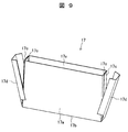
- FIG. 5 is an exploded perspective view illustrating the configuration of the insulating sheet according to the second embodiment
- FIG. 6 is an exploded perspective view of FIG. 5
- FIG. 7 is an exploded perspective view of FIG. It is a perspective view from which an inclination angle differs.
- the second insulating sheets 15 and 16 are interposed between the wound electrode group 40 and the current collecting plates 21 and 31, and the first insulating portions 15d and 16d, and the current collecting plate. 21 and 31 and the 2nd insulation parts 15e and 16e interposed between the battery cover 3 are.
- the second insulating sheets 15 and 16 are bent at the upper end portion of the facing surface portion 15a and protrude in the same direction as the pair of side surface portions 15b and 16b, and the pair of side surface portions 15b and 16b.
- the second insulating portions 15e and 16e are bent and overlapped with each other at the upper end portions thereof.
- the first insulating portion 15d is located between the curved portion 40c of the wound electrode group 40 and the main body portion 22 of the current collector plate 21.
- the second insulating portion 15 e is interposed between the main body portion 22 of the current collector plate 21 and the back surface of the battery lid 3.
- the first insulating portion 16 d becomes the curved portion 40 c of the wound electrode group 40 and the main body portion 32 of the current collector plate 31.
- the second insulating portion 16e is interposed between the main body portion 32 of the current collector plate 31 and the back surface of the battery lid 3.
- the first insulating portions 15d and 16d collect the current collected from the wound electrode group 40.
- a short circuit between the plates 21 and 31 can be prevented, and a short circuit between the current collector plates 21 and 31 and the battery cover 3 can be prevented by the second insulating portions 15e and 16e.
- first insulating portions 15d and 16d are provided with cutout portions 15f and 16f with the central portion cut out in a concave shape at the tips of the first insulating portions 15d and 16d.
- the notches 15f and 16f facilitate the operation of inserting the tips of the first insulating portions 15d and 16d between the curved portion 40c of the wound electrode group 40 and the main body portions 22 and 32 of the current collector plates 21 and 31. It is for making.
- the gap between the curved portion 40c of the wound electrode group 40 and the main body portions 22 and 32 of the current collector plates 21 and 31 is narrowest at the central portion, and from the central portion. The further away, the larger the gap. Therefore, when the first insulating portions 15d and 16d are to be inserted between the curved portion 40c of the wound electrode group 40 and the main body portions 22 and 32 of the current collector plates 21 and 31, the first insulating portions 15d and 16d If the tip has a simple linear shape, there is a possibility that it will be difficult to insert due to contact with the narrow central part of the gap.
- the wound electrode group 40 by providing notches 15f and 16f at the tips of the first insulating portions 15d and 16d and forming a double mountain shape in which both end portions in the width direction protrude from the central portion, first, the wound electrode group 40 and The tips of the first insulating portions 15d and 16d can be inserted where the gaps between the current collector plates 21 and 31 and the main body portions 22 and 32 are wide. If the tips of the first insulating portions 15d and 16d can be inserted, the first insulating portions 15d and 16d are smoothly inserted into the central portion where the gap is narrow, after that, by being pushed forward as it is. can do.
- the second insulating sheets 15 and 16 are thicker than the first insulating sheet 14 as in the first embodiment. Therefore, for example, when external pressure is applied to the battery container 2, the wound electrode group 40 and the current collector plates 21 and 31, and the current collector plates 21 and 31 and the battery cover 3 are brought into close contact with each other. Even if a flattened deformation occurs, sufficient insulation can be ensured.
- FIG. 8 is an exploded perspective view illustrating the configuration of the insulating sheet according to the third embodiment. What is characteristic in the present embodiment is that the pair of left and right second insulating sheets 15 and 16 are connected to each other by a connecting portion 111 and are integrally formed.
- the second insulating sheets 15 and 16 are thicker than the first insulating sheet 14 as in the first embodiment.
- the connection portion 111 is provided with an opening 111a.
- the opening 111a is formed so as to extend at a constant width in the left-right direction at the center in the width direction of the connecting portion 111.
- the wound electrode group 40 is covered with a total of three insulating sheets, but in the third embodiment, it is covered with a total of two insulating sheets.
- the conveyance and position designation of the insulating sheet at the time of assembling becomes easier, and the assembling work can be facilitated.
- FIG. 9 is a perspective view illustrating the configuration of the insulating sheet according to the fourth embodiment, and shows a state in which a part of the insulating sheet is developed.
- the first insulating sheet 14 and the second insulating sheets 15 and 16 are formed by bending a single insulating sheet 17 having a predetermined constant thickness. Between the mixture layer stacking region 40d of the rotating electrode group 40 and the battery can 4, only one insulating sheet 17 is interposed to reduce the sheet thickness as much as possible, while the metal foil exposed portions 41c and 42c and the battery are removed. That is, between the can 4 and between the current collector plates 21, 31 and the battery can 4, the insulating sheet 17 is partially folded and overlapped to increase the thickness and ensure the necessary strength. .
- the insulating sheet 17 has substantially the same thickness as the first insulating sheet 14 of the first to third embodiments described above.
- the insulating sheet 17 is formed in a flat box shape capable of accommodating the wound electrode group 40 by bending one sheet, and a pair of wide surface portions 17a facing the mixture layer stacking region 40d of the wound electrode group 40. , 17a and a bottom surface portion 17b.
- the 1st side wall surface part 17c is provided in the both ends of each wide surface part 17a.
- the first side wall surface portion 17c is formed by being bent at both ends of each wide surface portion 17a so as to face the end surface of the wound electrode group 40 on the outer side in the winding axis direction.
- the 2nd side wall surface part 17d is provided in the both ends of the bottom face part 17b.
- the second side wall surface portion 17d has a U-shaped cross section that covers the outside of the first side wall surface portion 17c, and is formed by being bent at both ends of the bottom surface portion 17b.
- the second side wall surface portion 17d has a size interposed between the metal foil exposed portions 41c and 42c of the wound electrode group 40 and the battery can 4 and between the current collecting plates 21 and 31 and the battery can 4. Have.
- the sheet thickness of the insulating sheet 17 interposed between the mixture layer stacking region 40d of the wound electrode group 40 and the battery can is set to the thickness of one insulating sheet 17.
- the thickness of the insulating sheet 17 can be two sheets or three sheets.
- the total thickness (number of windings) of the mixture layer stacking region 40d of the wound electrode group 40 is limited, so that the battery capacity can be prevented from decreasing and sufficient insulation can be ensured.
- the insulation between the wound electrode group 40 and the battery can 4 can be formed with only one thin insulating sheet 17. Therefore, the part cost can be suppressed and the assemblability can be improved.
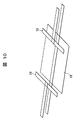
- FIG. 10 is a perspective view for explaining the configuration of the insulating sheet in the fifth embodiment, and shows a developed state of the insulating sheet.
- What is characteristic in the present embodiment is that, for one insulating sheet 18 having a predetermined constant thickness, between the metal foil exposed portions 41c and 42c and the battery can 4 and current collection.
- another insulating sheet 19 is further bonded to a portion interposed between the plates 21 and 31 and the battery can 4 to increase the thickness and secure the necessary strength.
- Insulation is performed in a thin state without attaching the insulating sheet 19 to the portion of the wound electrode group 40 facing the mixture layer stacking region 40d, which leads to an increase in battery capacity and a high volume energy density. In addition, battery swelling can be prevented.
- the insulating sheet 19 may be one sheet or a plurality of sheets. By pasting together in advance, the shape of the insulating sheet can be simplified, and assemblability can be improved.
- the present invention is not limited to the above-described embodiments, and various designs can be made without departing from the spirit of the present invention described in the claims. It can be changed.
- the above-described embodiment has been described in detail for easy understanding of the present invention, and is not necessarily limited to one having all the configurations described.
- a part of the configuration of an embodiment can be replaced with the configuration of another embodiment, and the configuration of another embodiment can be added to the configuration of an embodiment.
Abstract
Description
[全体構造]
本発明の二次電池を、角形のリチウムイオン二次電池に適用した場合について、図面と共に説明する。
次に、絶縁シート5の構成について図2を参照して説明する。
次に、本発明の二次電池が適用される第2実施形態について以下に説明する。なお、第1実施形態と同様の構成要素には同一の符号を付することでその詳細な説明を省略する。
次に、第3実施形態について以下に説明する。なお、上述の第1、第2実施形態と同様の構成要素には、同一の符号を付することでその詳細な説明を省略する。
次に、第4実施形態について以下に説明する。なお、第1~第3実施形態と同様の構成要素には同一の符号を付することでその詳細な説明を省略する。
次に、第5実施形態について以下に説明する。上述の第1~第4実施形態と同様の構成要素には、同一の符号を付することでその詳細な説明を省略する。
2 電池容器
3 電池蓋
4 電池缶
5 絶縁シート
11 注液栓
13 安全弁
14 第1の絶縁シート
15、16 第2の絶縁シート
21 正極側集電板
31 負極側集電板
40 捲回電極群
41 正極電極
41b 正極合剤層
41c 正極金属箔露出部(正極合剤未処理部)
42 負極電極
42b 負極合剤層
42c 負極金属箔露出部(負極合剤未処理部)
Claims (7)
- 金属箔に合剤層が形成された電極を捲回した捲回電極群と、前記捲回電極群を収容する電池缶と、前記捲回電極群と前記電池缶との間に介在される絶縁体とを有する二次電池であって、
前記絶縁体は、前記捲回電極群の捲回軸方向中央に形成された合剤層積層領域と前記電池缶との間に介在される部位よりも、前記捲回電極群の捲回軸方向両側に形成された一対の金属箔露出部と前記電池缶との間に介在される部位の方が厚さが厚いことを特徴とする二次電池。 - 前記合剤層積層領域を覆う第1の絶縁シートと、
前記一対の金属箔露出部を覆う一対の第2の絶縁シートと、を有し、
前記一対の第2の絶縁シートは、前記第1の絶縁シートよりもシート厚みが厚いことを特徴とする請求項1に記載の二次電池。 - 前記金属箔露出部に接続される集電板を有し、
前記一対の第2の絶縁シートは、前記金属箔露出部と前記集電板を覆う構成を有することを特徴とする請求項2に記載の二次電池。 - 前記集電板が取り付けられる電池蓋を有し、
前記集電板は、前記電池蓋と前記金属箔露出部との間に介在される本体部を有し、
前記一対の第2の絶縁シートは、前記金属箔露出部と前記本体部との間に介在される第1絶縁部と、前記本体部と前記電池蓋との間に介在される第2絶縁部を有することを特徴とする請求項3に記載の二次電池。 - 前記一対の第2の絶縁シートは、接続部で互いに接続されており、
該接続部は、前記捲回電極群と対向する位置に開口部が設けられていることを特徴とする請求項3に記載の二次電池。 - 予め設定された一定の厚さを有する1枚の絶縁シートを折り曲げることによって、前記第1の絶縁シートと前記第2の絶縁シートを構成したことを特徴とする請求項2に記載の二次電池。
- 前記金属箔露出部に接続される集電板を有し、
予め設定された一定の厚さを有する1枚の絶縁シートに対して、前記金属箔露出部と前記電池缶との間、及び、前記集電板と前記電池缶との間に介在される部分にさらに1枚以上の他の絶縁シートを貼り合わせて前記第1の絶縁シートと前記第2の絶縁シートを構成したことを特徴とする請求項2に記載の二次電池。
Priority Applications (5)
| Application Number | Priority Date | Filing Date | Title |
|---|---|---|---|
| JP2013523432A JP5336024B1 (ja) | 2012-01-23 | 2012-01-23 | 二次電池 |
| CN201280067872.9A CN104067411A (zh) | 2012-01-23 | 2012-01-23 | 二次电池 |
| PCT/JP2012/051298 WO2013111256A1 (ja) | 2012-01-23 | 2012-01-23 | 二次電池 |
| US14/373,453 US20140377607A1 (en) | 2012-01-23 | 2012-01-23 | Secondary battery |
| EP12866530.4A EP2808925A4 (en) | 2012-01-23 | 2012-01-23 | SECONDARY BATTERY |
Applications Claiming Priority (1)
| Application Number | Priority Date | Filing Date | Title |
|---|---|---|---|
| PCT/JP2012/051298 WO2013111256A1 (ja) | 2012-01-23 | 2012-01-23 | 二次電池 |
Publications (1)
| Publication Number | Publication Date |
|---|---|
| WO2013111256A1 true WO2013111256A1 (ja) | 2013-08-01 |
Family
ID=48873029
Family Applications (1)
| Application Number | Title | Priority Date | Filing Date |
|---|---|---|---|
| PCT/JP2012/051298 WO2013111256A1 (ja) | 2012-01-23 | 2012-01-23 | 二次電池 |
Country Status (5)
| Country | Link |
|---|---|
| US (1) | US20140377607A1 (ja) |
| EP (1) | EP2808925A4 (ja) |
| JP (1) | JP5336024B1 (ja) |
| CN (1) | CN104067411A (ja) |
| WO (1) | WO2013111256A1 (ja) |
Cited By (15)
| Publication number | Priority date | Publication date | Assignee | Title |
|---|---|---|---|---|
| JP2014038736A (ja) * | 2012-08-13 | 2014-02-27 | Toyota Industries Corp | 蓄電装置 |
| JP2015032549A (ja) * | 2013-08-06 | 2015-02-16 | 株式会社豊田自動織機 | 蓄電装置 |
| JP2015046319A (ja) * | 2013-08-28 | 2015-03-12 | 株式会社豊田自動織機 | 蓄電装置 |
| JP2015060712A (ja) * | 2013-09-18 | 2015-03-30 | 株式会社東芝 | 二次電池 |
| KR20150105849A (ko) * | 2014-03-10 | 2015-09-18 | 삼성에스디아이 주식회사 | 절연부재를 갖는 이차 전지 |
| CN106104880A (zh) * | 2014-03-18 | 2016-11-09 | 大众汽车有限公司 | 具有吹扫气体路径的燃料电池装置 |
| JP2016197555A (ja) * | 2015-04-03 | 2016-11-24 | トヨタ自動車株式会社 | 電池 |
| KR20170034122A (ko) * | 2015-09-18 | 2017-03-28 | 삼성에스디아이 주식회사 | 이차전지 |
| WO2017158704A1 (ja) * | 2016-03-14 | 2017-09-21 | 株式会社村田製作所 | 蓄電デバイス |
| WO2017158702A1 (ja) * | 2016-03-14 | 2017-09-21 | 株式会社村田製作所 | 蓄電デバイス |
| JP2018503959A (ja) * | 2015-01-30 | 2018-02-08 | ローベルト ボッシュ ゲゼルシャフト ミット ベシュレンクテル ハフツング | バッテリセル、及び、バッテリシステム |
| JP2018056085A (ja) * | 2016-09-30 | 2018-04-05 | 日立オートモティブシステムズ株式会社 | 二次電池 |
| WO2018159581A1 (ja) * | 2017-03-03 | 2018-09-07 | 株式会社Gsユアサ | 蓄電素子 |
| JP2018147618A (ja) * | 2017-03-02 | 2018-09-20 | 株式会社Gsユアサ | 蓄電素子 |
| CN113287222A (zh) * | 2019-03-20 | 2021-08-20 | 日本汽车能源株式会社 | 二次电池 |
Families Citing this family (7)
| Publication number | Priority date | Publication date | Assignee | Title |
|---|---|---|---|---|
| CN106098979B (zh) | 2009-05-20 | 2020-01-17 | 江森自控帅福得先进能源动力系统有限责任公司 | 锂离子电池模块 |
| JP5925142B2 (ja) * | 2013-02-21 | 2016-05-25 | 日立オートモティブシステムズ株式会社 | 二次電池 |
| DE102014202348A1 (de) * | 2014-02-10 | 2015-08-13 | Robert Bosch Gmbh | Vorrichtung und Verfahren zur Erhöhung der Sicherheit beim Gebrauch von Batteriesystemen |
| JP6208708B2 (ja) * | 2015-03-31 | 2017-10-04 | トヨタ自動車株式会社 | リチウムイオン二次電池およびそれを用いたシステム |
| JP6521779B2 (ja) * | 2015-07-23 | 2019-05-29 | 日立オートモティブシステムズ株式会社 | 二次電池 |
| CN109196702A (zh) * | 2016-06-24 | 2019-01-11 | 株式会社杰士汤浅国际 | 蓄电元件 |
| JP7230537B2 (ja) | 2018-01-31 | 2023-03-01 | 株式会社Gsユアサ | 蓄電素子 |
Citations (7)
| Publication number | Priority date | Publication date | Assignee | Title |
|---|---|---|---|---|
| JPH09120842A (ja) * | 1995-10-26 | 1997-05-06 | Sony Corp | リチウムイオン二次電池 |
| JP2007226989A (ja) | 2006-02-21 | 2007-09-06 | Sanyo Electric Co Ltd | 角形電池 |
| JP2009170137A (ja) * | 2008-01-11 | 2009-07-30 | Sanyo Electric Co Ltd | 角形電池 |
| JP2010287456A (ja) | 2009-06-12 | 2010-12-24 | Toyota Motor Corp | 電池 |
| JP2011049066A (ja) | 2009-08-27 | 2011-03-10 | Toshiba Corp | 電池 |
| JP2011181485A (ja) * | 2010-02-05 | 2011-09-15 | Sanyo Electric Co Ltd | 角形電池及びその製造方法ならびにこれを用いてなる組電池 |
| JP2011198663A (ja) * | 2010-03-23 | 2011-10-06 | Hitachi Vehicle Energy Ltd | 二次電池とその製造方法 |
Family Cites Families (5)
| Publication number | Priority date | Publication date | Assignee | Title |
|---|---|---|---|---|
| KR100599709B1 (ko) * | 2004-07-28 | 2006-07-12 | 삼성에스디아이 주식회사 | 이차 전지 |
| KR100807029B1 (ko) * | 2006-03-28 | 2008-02-25 | 삼성에스디아이 주식회사 | 이차전지 |
| US8574753B2 (en) * | 2009-08-27 | 2013-11-05 | Kabushiki Kaisha Toshiba | Battery comprising a conductive nipping member |
| KR101137363B1 (ko) * | 2009-11-16 | 2012-04-23 | 에스비리모티브 주식회사 | 이차전지 |
| CN102290550B (zh) * | 2010-06-21 | 2015-05-13 | 株式会社东芝 | 电池 |
-
2012
- 2012-01-23 US US14/373,453 patent/US20140377607A1/en not_active Abandoned
- 2012-01-23 JP JP2013523432A patent/JP5336024B1/ja active Active
- 2012-01-23 CN CN201280067872.9A patent/CN104067411A/zh active Pending
- 2012-01-23 WO PCT/JP2012/051298 patent/WO2013111256A1/ja active Application Filing
- 2012-01-23 EP EP12866530.4A patent/EP2808925A4/en not_active Withdrawn
Patent Citations (7)
| Publication number | Priority date | Publication date | Assignee | Title |
|---|---|---|---|---|
| JPH09120842A (ja) * | 1995-10-26 | 1997-05-06 | Sony Corp | リチウムイオン二次電池 |
| JP2007226989A (ja) | 2006-02-21 | 2007-09-06 | Sanyo Electric Co Ltd | 角形電池 |
| JP2009170137A (ja) * | 2008-01-11 | 2009-07-30 | Sanyo Electric Co Ltd | 角形電池 |
| JP2010287456A (ja) | 2009-06-12 | 2010-12-24 | Toyota Motor Corp | 電池 |
| JP2011049066A (ja) | 2009-08-27 | 2011-03-10 | Toshiba Corp | 電池 |
| JP2011181485A (ja) * | 2010-02-05 | 2011-09-15 | Sanyo Electric Co Ltd | 角形電池及びその製造方法ならびにこれを用いてなる組電池 |
| JP2011198663A (ja) * | 2010-03-23 | 2011-10-06 | Hitachi Vehicle Energy Ltd | 二次電池とその製造方法 |
Non-Patent Citations (1)
| Title |
|---|
| See also references of EP2808925A4 |
Cited By (20)
| Publication number | Priority date | Publication date | Assignee | Title |
|---|---|---|---|---|
| JP2014038736A (ja) * | 2012-08-13 | 2014-02-27 | Toyota Industries Corp | 蓄電装置 |
| JP2015032549A (ja) * | 2013-08-06 | 2015-02-16 | 株式会社豊田自動織機 | 蓄電装置 |
| JP2015046319A (ja) * | 2013-08-28 | 2015-03-12 | 株式会社豊田自動織機 | 蓄電装置 |
| JP2015060712A (ja) * | 2013-09-18 | 2015-03-30 | 株式会社東芝 | 二次電池 |
| KR20150105849A (ko) * | 2014-03-10 | 2015-09-18 | 삼성에스디아이 주식회사 | 절연부재를 갖는 이차 전지 |
| KR102197407B1 (ko) * | 2014-03-10 | 2020-12-31 | 삼성에스디아이 주식회사 | 절연부재를 갖는 이차 전지 |
| US10673083B2 (en) | 2014-03-18 | 2020-06-02 | Audi Ag | Fuel cell device with a flushing gas path |
| CN106104880A (zh) * | 2014-03-18 | 2016-11-09 | 大众汽车有限公司 | 具有吹扫气体路径的燃料电池装置 |
| JP2018503959A (ja) * | 2015-01-30 | 2018-02-08 | ローベルト ボッシュ ゲゼルシャフト ミット ベシュレンクテル ハフツング | バッテリセル、及び、バッテリシステム |
| US10158107B2 (en) | 2015-04-03 | 2018-12-18 | Toyota Jidosha Kabushiki Kaisha | Battery comprising insulative films |
| JP2016197555A (ja) * | 2015-04-03 | 2016-11-24 | トヨタ自動車株式会社 | 電池 |
| KR20170034122A (ko) * | 2015-09-18 | 2017-03-28 | 삼성에스디아이 주식회사 | 이차전지 |
| KR102524471B1 (ko) * | 2015-09-18 | 2023-04-24 | 삼성에스디아이 주식회사 | 이차전지 |
| WO2017158702A1 (ja) * | 2016-03-14 | 2017-09-21 | 株式会社村田製作所 | 蓄電デバイス |
| WO2017158704A1 (ja) * | 2016-03-14 | 2017-09-21 | 株式会社村田製作所 | 蓄電デバイス |
| JP2018056085A (ja) * | 2016-09-30 | 2018-04-05 | 日立オートモティブシステムズ株式会社 | 二次電池 |
| JP2018147618A (ja) * | 2017-03-02 | 2018-09-20 | 株式会社Gsユアサ | 蓄電素子 |
| WO2018159581A1 (ja) * | 2017-03-03 | 2018-09-07 | 株式会社Gsユアサ | 蓄電素子 |
| CN113287222A (zh) * | 2019-03-20 | 2021-08-20 | 日本汽车能源株式会社 | 二次电池 |
| CN113287222B (zh) * | 2019-03-20 | 2024-03-19 | 日本汽车能源株式会社 | 二次电池 |
Also Published As
| Publication number | Publication date |
|---|---|
| JPWO2013111256A1 (ja) | 2015-05-11 |
| CN104067411A (zh) | 2014-09-24 |
| EP2808925A1 (en) | 2014-12-03 |
| EP2808925A4 (en) | 2015-10-21 |
| US20140377607A1 (en) | 2014-12-25 |
| JP5336024B1 (ja) | 2013-11-06 |
Similar Documents
| Publication | Publication Date | Title |
|---|---|---|
| JP5336024B1 (ja) | 二次電池 | |
| JP5841571B2 (ja) | 二次電池 | |
| CN107710459B (zh) | 电池及电池包 | |
| JP5452303B2 (ja) | 二次電池とその製造方法 | |
| CN108028348B (zh) | 蓄电元件以及蓄电元件的制造方法 | |
| JP6270613B2 (ja) | 角形二次電池 | |
| JP2011049065A (ja) | 非水電解質電池およびその製造方法 | |
| JP2011049064A (ja) | 電池 | |
| WO2013176183A1 (ja) | リチウムイオン電池 | |
| JP5779562B2 (ja) | 角形電池 | |
| WO2013027296A1 (ja) | リチウムイオン二次電池およびその製造方法 | |
| JP2018534726A (ja) | 蓄電素子及び蓄電素子の製造方法 | |
| JP6045987B2 (ja) | 角形二次電池 | |
| JP7118242B2 (ja) | 二次電池 | |
| JP2016100046A (ja) | 角形二次電池 | |
| JP5925142B2 (ja) | 二次電池 | |
| CN108140794B (zh) | 蓄电元件以及蓄电元件的制造方法 | |
| JP6232213B2 (ja) | 二次電池及びその製造方法 | |
| JP2018060599A (ja) | 角形二次電池 | |
| JP2015125840A (ja) | 二次電池 | |
| US20130323557A1 (en) | Secondary battery and method for manufacturing same | |
| JP6718985B2 (ja) | 角形二次電池 | |
| JP6715936B2 (ja) | 角形二次電池 | |
| JP6752691B2 (ja) | 二次電池 | |
| JP2019087418A (ja) | 電池 |
Legal Events
| Date | Code | Title | Description |
|---|---|---|---|
| ENP | Entry into the national phase |
Ref document number: 2013523432 Country of ref document: JP Kind code of ref document: A |
|
| 121 | Ep: the epo has been informed by wipo that ep was designated in this application |
Ref document number: 12866530 Country of ref document: EP Kind code of ref document: A1 |
|
| REEP | Request for entry into the european phase |
Ref document number: 2012866530 Country of ref document: EP |
|
| WWE | Wipo information: entry into national phase |
Ref document number: 2012866530 Country of ref document: EP Ref document number: 14373453 Country of ref document: US |
|
| NENP | Non-entry into the national phase |
Ref country code: DE |