WO2013094564A1 - 載置台及びプラズマ処理装置 - Google Patents
載置台及びプラズマ処理装置 Download PDFInfo
- Publication number
- WO2013094564A1 WO2013094564A1 PCT/JP2012/082681 JP2012082681W WO2013094564A1 WO 2013094564 A1 WO2013094564 A1 WO 2013094564A1 JP 2012082681 W JP2012082681 W JP 2012082681W WO 2013094564 A1 WO2013094564 A1 WO 2013094564A1
- Authority
- WO
- WIPO (PCT)
- Prior art keywords
- adhesive
- hole
- electrostatic chuck
- mounting table
- base
- Prior art date
- Legal status (The legal status is an assumption and is not a legal conclusion. Google has not performed a legal analysis and makes no representation as to the accuracy of the status listed.)
- Ceased
Links
Images


Classifications
-
- H—ELECTRICITY
- H10—SEMICONDUCTOR DEVICES; ELECTRIC SOLID-STATE DEVICES NOT OTHERWISE PROVIDED FOR
- H10P—GENERIC PROCESSES OR APPARATUS FOR THE MANUFACTURE OR TREATMENT OF DEVICES COVERED BY CLASS H10
- H10P72/00—Handling or holding of wafers, substrates or devices during manufacture or treatment thereof
- H10P72/70—Handling or holding of wafers, substrates or devices during manufacture or treatment thereof for supporting or gripping
- H10P72/72—Handling or holding of wafers, substrates or devices during manufacture or treatment thereof for supporting or gripping using electrostatic chucks
- H10P72/722—Details of electrostatic chucks
-
- H—ELECTRICITY
- H10—SEMICONDUCTOR DEVICES; ELECTRIC SOLID-STATE DEVICES NOT OTHERWISE PROVIDED FOR
- H10P—GENERIC PROCESSES OR APPARATUS FOR THE MANUFACTURE OR TREATMENT OF DEVICES COVERED BY CLASS H10
- H10P72/00—Handling or holding of wafers, substrates or devices during manufacture or treatment thereof
- H10P72/70—Handling or holding of wafers, substrates or devices during manufacture or treatment thereof for supporting or gripping
- H10P72/72—Handling or holding of wafers, substrates or devices during manufacture or treatment thereof for supporting or gripping using electrostatic chucks
-
- H—ELECTRICITY
- H01—ELECTRIC ELEMENTS
- H01J—ELECTRIC DISCHARGE TUBES OR DISCHARGE LAMPS
- H01J37/00—Discharge tubes with provision for introducing objects or material to be exposed to the discharge, e.g. for the purpose of examination or processing thereof
- H01J37/32—Gas-filled discharge tubes
- H01J37/32009—Arrangements for generation of plasma specially adapted for examination or treatment of objects, e.g. plasma sources
- H01J37/32082—Radio frequency generated discharge
- H01J37/32091—Radio frequency generated discharge the radio frequency energy being capacitively coupled to the plasma
-
- H—ELECTRICITY
- H01—ELECTRIC ELEMENTS
- H01J—ELECTRIC DISCHARGE TUBES OR DISCHARGE LAMPS
- H01J37/00—Discharge tubes with provision for introducing objects or material to be exposed to the discharge, e.g. for the purpose of examination or processing thereof
- H01J37/32—Gas-filled discharge tubes
- H01J37/32431—Constructional details of the reactor
- H01J37/32715—Workpiece holder
-
- H—ELECTRICITY
- H10—SEMICONDUCTOR DEVICES; ELECTRIC SOLID-STATE DEVICES NOT OTHERWISE PROVIDED FOR
- H10P—GENERIC PROCESSES OR APPARATUS FOR THE MANUFACTURE OR TREATMENT OF DEVICES COVERED BY CLASS H10
- H10P50/00—Etching of wafers, substrates or parts of devices
- H10P50/20—Dry etching; Plasma etching; Reactive-ion etching
- H10P50/24—Dry etching; Plasma etching; Reactive-ion etching of semiconductor materials
- H10P50/242—Dry etching; Plasma etching; Reactive-ion etching of semiconductor materials of Group IV materials
-
- H—ELECTRICITY
- H10—SEMICONDUCTOR DEVICES; ELECTRIC SOLID-STATE DEVICES NOT OTHERWISE PROVIDED FOR
- H10P—GENERIC PROCESSES OR APPARATUS FOR THE MANUFACTURE OR TREATMENT OF DEVICES COVERED BY CLASS H10
- H10P72/00—Handling or holding of wafers, substrates or devices during manufacture or treatment thereof
- H10P72/70—Handling or holding of wafers, substrates or devices during manufacture or treatment thereof for supporting or gripping
Definitions
- Various aspects and embodiments of the present invention relate to a mounting table and a plasma processing apparatus.
- the plasma processing apparatus includes a processing container that can maintain a vacuum environment, and generally has a configuration in which a substrate to be processed is disposed below the processing container (processing space) and plasma processing is performed by supplying RF power. It is. Therefore, the plasma processing apparatus is configured to satisfy various functions such as a function of supplying power to the substrate to be processed as well as a function of holding the substrate to be processed in the processing space.
- Patent Document 1 as a configuration satisfying various functions as described above, a processing container in which a conductive material, for example, the surface is formed into a cylinder or a rectangle by anodized aluminum or the like, and a processing space is formed therein. And a cylindrical base fixed on an insulating member, for example, an insulating plate such as ceramics, on the bottom of the processing container, and a disk-shaped heater fixing base placed on the upper surface of the base.
- a multiple structure including a mounting table that also serves as an electrode for supplying RF power from the lower part so as to include the heater fixing table from above.
- the diameter is substantially the same as the substrate to be processed, preferably slightly smaller than the diameter of the substrate to be processed.
- a structure comprising an electrostatic chuck is also described.
- Patent Document 2 incorporates a support base that can be controlled to a desired first set temperature, and one or more heating elements provided to heat to a second set temperature that is higher than the first set temperature.
- a structure is described in which the substrate support is integrally bonded and bonded with an erosion-resistant heat insulating material made of an acrylic material.
- Patent Document 3 a through-hole that penetrates the base and the electrostatic chuck is formed between the upper surface of the mounting table and the back surface of the substrate, and an insulating sleeve is formed on the side wall of the through-hole. A structure in which is adhered is described.
- JP-A-7-183279 JP 2008-85329 A Japanese Patent No. 4095842
- the mounting table incorporates structural members for realizing various functions and is directly exposed to plasma or radicals generated by plasma processing.
- an adhesive for adhesively bonding a member such as an erosion-resistant heat insulating material made of an acrylic material is exposed to plasma or radicals, so that its composition components are damaged, etc.
- the adhesive used for adhesive bonding of the electrostatic chuck is consumed or deteriorated, it becomes difficult to control the heat conduction to the member coupled to the electrostatic chuck. As a result, uniform and accurate process processing over the substrate surface cannot be performed.
- the mounting table includes an electrostatic chuck, a base, and a cylindrical sleeve.
- the electrostatic chuck has a surface exposed to plasma and a back surface facing the surface, and a first through hole is formed.
- the base is joined to the back surface of the electrostatic chuck by a first adhesive, and communicates with the first through hole to form a second through hole having a larger diameter than the first through hole.
- the sleeve is joined to the back surface of the electrostatic chuck in a state of communicating with the first through hole by the second adhesive.
- the second through hole formed in the base has a larger diameter than the first through hole formed in the electrostatic chuck, and thus communicates with the first through hole.
- the cylindrical sleeve can be bonded to the back surface of the electrostatic chuck with an adhesive.
- the electrostatic chuck and the base are bonded by the first adhesive, and the electrostatic chuck and the sleeve are bonded by the second adhesive. That is, since the plasma or radicals flowing from the first through hole or the second through hole are blocked by the sleeve, the first adhesive, that is, the adhesive used for adhesive bonding of the electrostatic chuck is directly exposed to the plasma or radical. Can be prevented.
- the second adhesive is used for joining the sleeve, it is possible to prevent the first adhesive joining the electrostatic chuck and the sleeve from being directly exposed to plasma or radicals. . Therefore, according to the mounting table which concerns on 1 side of this invention, deterioration of the adhesive agent used for the adhesive bond of an electrostatic chuck can be prevented.
- the sleeve may be joined to the back surface of the electrostatic chuck so as to have the same inner diameter as the first through hole and to be coaxial with the first through hole.
- the first through hole and the sleeve can form a continuous through hole in the joint portion.
- the through hole can be configured as a gas flow path with less resistance loss. Become.
- the first adhesive may be provided only at the contact portion between the electrostatic chuck and the base. With this configuration, since the first adhesive is not provided on the back surface portion of the electrostatic chuck that faces the second through hole, the degree of freedom in the joining position of the sleeve to be joined to the back surface of the electrostatic chuck In addition, the first adhesive can be further prevented from being directly exposed to plasma or radicals.
- the sleeve may have a smaller outer diameter than the second through hole.
- a sleeve can be appropriately arrange
- a sealant filled in a space region defined by the sleeve and the second through hole may be further provided.
- the sealant may be filled into the space region by being poured into the space region defined by the sleeve and the second through hole and then cured. In this case, the sealant can be easily filled into the space region.
- the sealant may be an adhesive having a viscosity of 20000 cps or less before curing and a Young's modulus of 1 MPa or less after curing.
- the sealant can be easily filled in the space region defined by the sleeve and the second through hole before curing.
- the sealing material can reliably remain in the space region while being deformed following the thermal expansion of the base and the sleeve.
- the sleeve may be formed of the same insulator as that constituting the electrostatic chuck. By comprising in this way, it can be set as the structure which has high tolerance with respect to a plasma or a radical in a sleeve similarly to an electrostatic chuck.
- the sleeve may be formed of ceramic.
- the first adhesive may be an organic adhesive.
- the second adhesive may be an inorganic adhesive. Since the inorganic adhesive has heat resistance, deterioration of the adhesive used for adhesive bonding of the insulating sleeve can be prevented.
- the second adhesive may be an adhesive having higher resistance to plasma or radicals than the first adhesive.
- a plasma processing apparatus includes a processing container, a gas supply unit, a first electrode, and a mounting table.
- the processing container defines a processing space in which plasma is generated.
- the gas supply unit supplies a processing gas into the processing space.
- the first electrode is provided in the processing space.
- the mounting table is accommodated in the processing container and mounts the substrate.
- the mounting table includes an electrostatic chuck, a base, and a cylindrical sleeve.
- the electrostatic chuck has a surface exposed to plasma and a back surface facing the surface, and a first through hole is formed.
- the base is joined to the back surface of the electrostatic chuck by a first adhesive, and communicates with the first through hole to form a second through hole having a larger diameter than the first through hole.
- the sleeve is joined to the back surface of the electrostatic chuck in a state of communicating with the first through hole by the second adhesive.
- this plasma processing apparatus since the mounting table that can prevent the deterioration of the adhesive used for adhesive bonding of the electrostatic chuck is provided, it is possible to realize a plasma processing apparatus that operates stably. it can.
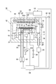
- FIG. 1 is a diagram schematically showing a plasma processing apparatus according to an embodiment.
- FIG. 1 shows a cross section of a plasma processing apparatus according to an embodiment.
- a plasma processing apparatus 10 shown in FIG. 1 is a parallel plate type plasma processing apparatus.
- the plasma processing apparatus 10 includes a processing container 12.
- the processing container 12 has a substantially cylindrical shape and defines a processing space S as its internal space.
- the plasma processing apparatus 10 includes a substantially disk-shaped base 14 in a processing container 12.
- the base 14 is provided below the processing space S.
- the base 14 is made of aluminum, for example, and constitutes a second electrode.
- the base 14 has a function of absorbing the heat of the electrostatic chuck 50 described later in the process and cooling the electrostatic chuck 50.
- a refrigerant flow path 15 is formed inside the base 14, and a refrigerant inlet pipe and a refrigerant outlet pipe are connected to the refrigerant flow path 15.
- the base 14 and the electrostatic chuck 50 can be controlled to a predetermined temperature by circulating an appropriate refrigerant such as cooling water in the refrigerant flow path 15.
- the plasma processing apparatus 10 further includes a cylindrical holding portion 16 and a cylindrical support portion 17.
- the cylindrical holding portion 16 holds the base 14 in contact with the side and bottom edges of the base 14.
- the cylindrical support portion 17 extends in the vertical direction from the bottom portion of the processing container 12 and supports the base 14 via the cylindrical holding portion 16.
- the plasma processing apparatus 10 further includes a focus ring 18 placed on the upper surface of the cylindrical holder 16.
- the focus ring 18 can be made of, for example, silicon or quartz.
- an exhaust path 20 is formed between the side wall of the processing vessel 12 and the cylindrical support portion 17.
- a baffle plate 22 is attached to the inlet of the exhaust passage 20 or in the middle thereof.
- An exhaust port 24 is provided at the bottom of the exhaust path 20.
- the exhaust port 24 is defined by an exhaust pipe 28 fitted in the bottom of the processing container 12.
- An exhaust device 26 is connected to the exhaust pipe 28.
- the exhaust device 26 has a vacuum pump and can depressurize the processing space S in the processing container 12 to a predetermined degree of vacuum.
- a gate valve 30 that opens and closes a loading / unloading port for a substrate (substrate) W to be processed is attached to the side wall of the processing container 12.
- the base 14 is electrically connected to a high-frequency power source 32 for plasma generation via a matching unit 34.
- the high frequency power supply 32 applies high frequency power of a predetermined high frequency (for example, 27 MHz or more) to the second electrode, that is, the base 14.
- the plasma processing apparatus 10 further includes a shower head 38 in the processing container 12.
- the shower head 38 is provided above the processing space S.
- the shower head 38 includes an electrode plate 40 and an electrode support 42.
- the electrode plate 40 is a conductive plate having a substantially disc shape and constitutes a first electrode.
- a high frequency power source 35 for plasma generation is electrically connected to the electrode plate 40 via a matching unit 36.
- the high frequency power supply 35 applies high frequency power of a predetermined high frequency (for example, 27 MHz or more) to the electrode plate 40.
- a high frequency electric field is formed in the space between the base 14 and the electrode plate 40, that is, the processing space S.
- the electrode plate 40 has a plurality of gas vent holes 40h.
- the electrode plate 40 is detachably supported by an electrode support 42.
- a buffer chamber 42 a is provided inside the electrode support 42.
- the plasma processing apparatus 10 further includes a gas supply unit 44, and the gas supply unit 44 is connected to the gas introduction port 25 of the buffer chamber 42 a through a gas supply conduit 46.
- the gas supply unit 44 supplies a processing gas to the processing space S.
- the gas supply unit 44 can supply, for example, a CF-based etching gas.
- the electrode support 42 is formed with a plurality of holes each continuous with the plurality of gas vent holes 40h, and the plurality of holes communicate with the buffer chamber 42a. Therefore, the gas supplied from the gas supply unit 44 is supplied to the processing space S via the buffer chamber 42a and the gas vent 40h.
- a magnetic field forming mechanism 48 extending annularly or concentrically is provided on the ceiling of the processing vessel 12.
- the magnetic field forming mechanism 48 functions to facilitate the start of high-frequency discharge (plasma ignition) in the processing space S and maintain stable discharge.
- an electrostatic chuck 50 is provided on the upper surface of the base 14.
- the electrostatic chuck 50 is a substantially disk-shaped member, and has a surface exposed to plasma and a back surface facing the surface.
- the electrostatic chuck 50 includes an electrode 52 and a pair of insulating films 54a and 54b.
- the insulating films 54a and 54b are films formed of an insulator such as ceramic.
- the electrode 52 is a conductive film and is provided between the insulating film 54a and the insulating film 54b.
- a direct current power source 56 is connected to the electrode 52 via a switch SW.
- a heater 53 which is a heating element, is embedded inside the electrostatic chuck 50 so that the substrate W to be processed can be heated to a predetermined temperature.
- the heater 53 is connected to a heater power supply via wiring.
- the base 14 and the electrostatic chuck 50 constitute a mounting table 70.
- the plasma processing apparatus 10 further includes gas supply lines 58 and 60 and heat transfer gas supply units 62 and 64.
- the heat transfer gas supply unit 62 is connected to a gas supply line 58.
- the gas supply line 58 extends to the upper surface of the electrostatic chuck 50 and extends in an annular shape at the central portion of the upper surface.
- the heat transfer gas supply unit 62 supplies a heat transfer gas such as He gas between the upper surface of the electrostatic chuck 50 and the substrate W to be processed.
- the heat transfer gas supply unit 64 is connected to the gas supply line 60.
- the gas supply line 60 extends to the upper surface of the electrostatic chuck 50 and extends in an annular shape so as to surround the gas supply line 58 on the upper surface.
- the heat transfer gas supply unit 64 supplies a heat transfer gas such as He gas between the upper surface of the electrostatic chuck 50 and the substrate W to be processed.
- the plasma processing apparatus 10 further includes a control unit 66.
- the control unit 66 is connected to the exhaust device 26, the switch SW, the high frequency power source 32, the matching unit 34, the high frequency power source 35, the matching unit 36, the gas supply unit 44, and the heat transfer gas supply units 62 and 64.
- the control unit 66 sends control signals to the exhaust device 26, the switch SW, the high frequency power supply 32, the matching unit 34, the high frequency power source 35, the matching unit 36, the gas supply unit 44, and the heat transfer gas supply units 62 and 64, respectively. To do.
- control unit 66 exhaust by the exhaust device 26, opening / closing of the switch SW, power supply from the high frequency power source 32, impedance adjustment of the matching unit 34, power supply from the high frequency power source 35, impedance adjustment of the matching unit 36,
- the supply of the processing gas by the gas supply unit 44 and the supply of the heat transfer gas by the heat transfer gas supply units 62 and 64 are controlled.
- the processing gas is supplied from the gas supply unit 44 to the processing space S. Further, a high frequency electric field is formed between the electrode plate 40 and the base 14, that is, in the processing space S. As a result, plasma is generated in the processing space S, and the substrate W to be processed is etched by radicals or the like of elements contained in the processing gas (for example, oxygen radicals).
- FIG. 2 is a partial end view of a position where the gas supply line 58 of the mounting table 70 shown in FIG. 1 is formed.
- the lower surface of the electrostatic chuck 50 is bonded and bonded to the upper surface of the base 14 with a first adhesive 71.
- the first adhesive 71 may be provided only on the contact portion (contact surface) between the electrostatic chuck 50 and the base 14.
- the first adhesive 71 has a function of absorbing a difference in deformation amount between the base 14 and the electrostatic chuck 50 having different linear expansion coefficients. For this reason, the 1st adhesive agent 71 has high elasticity.
- the first adhesive 71 has a function of conducting heat of the electrostatic chuck 50 to the base 14 and a function of electrically insulating the electrostatic chuck 50 and the base 14. For this reason, the first adhesive 71 has high thermal conductivity and electrical resistivity.
- an organic adhesive including a silicone material, an acrylic base or an acrylate base acrylic material, or a polyimide silica material can be used.
- the 1st adhesive agent 71 is good also as having the physical-property value shown below.
- Adhesive strength about 1 to 10 MPa (room temperature), about 0.5 to 5 MPa (150 ° C.)
- Elastic modulus about 100 to 300 MPa (room temperature), 0.1 to 2 MPa (150 ° C.)
- Thermal conductivity 0.2 W / m ⁇ K or more
- Volume resistivity 1 e + 13 ⁇ ⁇ cm or more (room temperature), 1e + 8 ⁇ ⁇ cm or more (150 ° C.)
- the gas supply line 58 includes an upper gas supply line 58a and a lower gas supply line 58b penetrating in the thickness direction of the electrostatic chuck 50 in the mounting table 70.
- the electrostatic chuck 50 is formed with a first through hole having a diameter R1 penetrating in the thickness direction, and the first through hole constitutes an upper gas supply line 58a.
- the base 14 is formed with a second through hole having a diameter R2 penetrating in the thickness direction, and the second through hole constitutes a lower gas supply line 58b.
- the electrostatic chuck 50 and the base 14 are disposed so that the first through hole and the second through hole communicate with each other.
- the upper gas supply line 58a and the lower gas supply line 58b constitute a through hole.
- the electrostatic chuck 50 and the base 14 are arranged so that the axis M1 (center axis) of the first through hole and the axis M2 (center axis) of the second through hole coincide with each other, that is, are coaxial.
- the diameter R1 of the first through hole is formed slightly smaller than the diameter R2 of the second through hole. That is, the diameter of the upper gas supply line 58a is slightly smaller than the diameter of the lower gas supply line 58b.
- An insulating sleeve 80 extending in the direction of the side wall 14A of the base 14 is provided in the lower gas supply line 58b. That is, the insulating sleeve 80 is accommodated in the second through hole of the base 14.
- the insulating sleeve 80 may be made of the same insulator as that constituting the electrostatic chuck, and is made of an insulator such as ceramic.
- the insulating sleeve 80 has a cylindrical shape, and a substantially cylindrical member is used here.
- the inner diameter R4 of the insulating sleeve 80 may be the same as the diameter R1 of the first through hole.
- the outer diameter R3 of the insulating sleeve 80 may be the same as or smaller than the diameter R2 of the second through hole.
- the length of the insulating sleeve 80 in the axial direction is formed to be substantially equal to the thickness of the base 14.
- One end of the insulating sleeve 80 is attached to the lower surface of the electrostatic chuck 50 and bonded to the peripheral edge of the upper gas supply line 58a by the second adhesive 72.
- the axis M3 of the insulating sleeve 80 and the axis M1 (center axis) of the first through hole coincide, that is, the insulating sleeve 80 and the first through hole are coaxial. It may be attached to.
- the second adhesive 72 has higher resistance to plasma or radicals than the first adhesive 71. Specifically, the second adhesive 72 has plasma wear resistance and radical (for example, oxygen radical) wear resistance comparable to ceramics, and has plasma permeability resistance and radical penetration resistance comparable to ceramics. It has sex.
- the second adhesive 72 for example, an inorganic adhesive containing a ceramic material can be used.
- an adhesive containing an inorganic oxide or an inorganic fluoride can be used.
- the space region G is defined by the insulating sleeve 80 and the inner wall of the second through hole (the side wall 14A of the base 14). Defined. That is, the insulating sleeve 80 is configured to be spaced apart from the side wall (inner wall of the second through hole) 14A of the base 14 by a predetermined distance. The size of the space region G is determined according to the linear expansion coefficient of the material constituting the insulating sleeve 80 and the material constituting the base 14 and the process temperature.
- the insulating sleeve 80 is made of ceramic, and the process temperature is 150 ° C., a deformation difference due to thermal expansion of about 0.3 mm occurs between the base 14 and the insulating sleeve 80. .
- the insulating sleeve 80 is arranged to be separated from the side wall 14A of the base 14 by 0.3 mm or more.
- a sealant 73 may be interposed between the side wall 14A of the base 14 and the insulating sleeve 80, that is, in the space region G.
- the sealing agent 73 blocks the first adhesive 71 from the atmosphere by sealing the space region G. That is, the sealant 73 functions to block radicals that deteriorate from the first adhesive 71 by flowing into the processing space S, wrapping around the insulating sleeve 80, and contacting the first adhesive 71. To do.
- the sealant 73 has such fluidity that it can be poured between the side wall 14A of the base 14 and the insulating sleeve 80 when the space region G is filled (that is, before curing).
- the sealing agent 73 is then cured to remain between the side wall 14A of the base 14 and the insulating sleeve 80, and seals the space region G between the side wall 14A of the base 14 and the insulating sleeve 80.
- the sealant 73 has higher elasticity than the second adhesive 72 and deforms following the thermal expansion of the base 14 and the insulating sleeve 80.
- the sealant 73 desirably has a viscosity of 20000 cps or less before curing, and desirably has a Young's modulus of 1 MPa or less after curing.
- an organic adhesive having an acrylic vinyl material, an acrylate ester material, or a styrene butadiene rubber material is used.
- a thermosetting resin, a casting resin that is, an injectable plastic or an elastomer compound), an elastomer, or the like may be used.
- FIG. 3 shows a general configuration of a conventional mounting table.
- the conventional mounting table 90 includes a base 92, an electrostatic chuck 94, and an insulating sleeve 96, and the base 92, the electrostatic chuck 94, and the insulating sleeve 96 are bonded with an organic adhesive 98.
- a heater 95 that is a heating element is embedded in the electrostatic chuck 94.
- a refrigerant flow path 93 through which the refrigerant circulates is formed.
- an upper gas supply line 99a that penetrates in the thickness direction of the electrostatic chuck 94 and a lower gas supply line 99b that penetrates in the thickness direction of the base 92 are formed.
- the electrostatic chuck 94 is formed with a through-hole having a diameter P1 penetrating in the thickness direction, and the through-hole forms an upper gas supply line 99a.
- the base 92 is formed with a through hole having a diameter P2 penetrating in the thickness direction, and the through hole constitutes the lower gas supply line 99b.
- the electrostatic chuck 94 and the base 92 are disposed so that the respective through holes communicate with each other.
- the electrostatic chuck 94 and the base 92 are arranged so that the axis M1 (center axis) of the through-hole having the diameter P1 and the axis M2 (center axis) of the through-hole having the diameter P2 are coincident with each other. Is done.
- the diameter P1 of the upper gas supply line 99a is slightly smaller than the diameter P2 of the lower gas supply line 99b.
- An insulating sleeve 96 extending in the direction of the side wall of the base 92 is provided in the lower gas supply line 99b.
- the inner diameter P4 of the insulating sleeve 96 is larger than the diameter R1
- the outer diameter P3 of the insulating sleeve 96 is smaller than the diameter R2.
- One end of the insulating sleeve 96 is attached so that the axis M3 of the insulating sleeve 96 and the axis M1 (center axis) of the through hole having the diameter P1 coincide.
- the organic adhesive 98 is exposed to the inside of the through hole in the vicinity of the upper gas supply line 99a and the lower end of the insulating sleeve 96.
- the substrate W to be processed is removed for the purpose of removing deposits of by-products on the inner wall of the processing vessel and the periphery of the electrostatic chuck 94.
- Perform waferless dry cleaning generally about 1 to 3 minutes to generate plasma.
- the mounting table 90 is directly exposed to plasma, and plasma and radicals flow into the through holes.
- the organic adhesive 98 will be damaged by the inflowing plasma and radical. In particular, in a process under a high temperature environment, deterioration and consumption of the organic adhesive 98 are promoted. As shown in FIG.
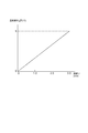
- FIG. 5 is a graph showing the relationship between the consumption amount of the organic adhesive 98 and the temperature change ⁇ T of the electrostatic chuck 94 when a silicone adhesive is used as the organic adhesive 98.
- the horizontal axis represents the amount of consumption of the organic adhesive 98 in the radial direction of the electrostatic chuck 94
- the vertical axis represents the temperature change ⁇ T of the electrostatic chuck 94.
- the consumption amount is evaluated by the length (mm) from the inner wall of the insulating sleeve 96 to the outer edge of the organic adhesive 98 in the radial direction of the electrostatic chuck 94.
- the temperature of the electrostatic chuck 94 increases.
- the temperature of the electrostatic chuck rises by 5 ° C. This is because the heat conduction from the electrostatic chuck 94 to the base 92 is hindered by the consumption of the organic adhesive 98, and the heat radiation amount of the base 92 is reduced.
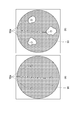
- FIG. 6 schematically shows the temperature distribution of the electrostatic chuck 94 when the heater 95 is heated to generate heat during the process steps.
- a silicone adhesive was used as the organic adhesive 98.
- FIG. 6A shows the temperature distribution of the electrostatic chuck 94 when the unused mounting table 90 is used
- FIG. 6B shows the plasma in which the total execution time of waferless dry cleaning is 120 hours. It is a temperature distribution of the electrostatic chuck 94 when the mounting table 90 that has been processed is used.
- the unused mounting table 90 shown in FIG. 6A.
- the temperature of the electrostatic chuck 94 is increased at the peripheral edge of the upper gas supply line 99a. This is because the organic adhesive 98 is exposed to plasma and radicals flowing from the processing space S through the upper gas supply line 99a, so that the organic adhesive 98 at the periphery of the upper gas supply line 99a is consumed and bonded. This is because the agent consumption region K is formed.
- the cooling performance around the through hole may be lowered depending on use.
- the insulating sleeve 80 is disposed inside the through-hole penetrating the base 14 and the electrostatic chuck 50 and separated from the side wall 14A of the base 14.
- the insulating sleeve 80 is bonded to the lower surface of the electrostatic chuck 50 with a second adhesive 72 having higher resistance to plasma or radicals than the first adhesive 71. That is, since the insulating sleeve 80 is disposed inside the through hole with respect to the side wall 14A of the base 14, plasma or radicals flowing from the through hole are blocked by the insulating sleeve 80, and the first adhesive 71 is directly applied to the plasma or Exposure to radicals is prevented.
- the second adhesive 72 used for the insulating sleeve 80 has high resistance to plasma or radicals, the influence of deterioration due to plasma or radicals is small. Therefore, according to the mounting table 70 according to the present embodiment, deterioration of the first adhesive 71 and the second adhesive 72 can be prevented. Further, even in a process under a high temperature environment (for example, 150 ° C. or higher), it is possible to appropriately prevent the first adhesive 71 and the second adhesive 72 from being deteriorated.
- a high temperature environment for example, 150 ° C. or higher
- the mounting table 70 includes a sealing agent 73 interposed between the side wall 14A of the base 14 and the insulating sleeve 80. For this reason, since the radical entering the insulating sleeve 80 and entering between the side wall 14A of the base 14 and the insulating sleeve 80 can be blocked by the sealing agent 73, the deterioration of the first adhesive 71 due to the radical is ensured. Can be prevented.
- the first adhesive 71 is not exposed to plasma or radicals by the sealant 73, so that the first adhesive 71 is not required to be resistant to plasma or radicals. That is, in the mounting table 70 according to the present embodiment, it is not necessary to select an adhesive material in consideration of resistance to plasma or radicals, and thus the degree of freedom in selecting the material of the first adhesive 71 can be increased. . That is, it is possible to employ, as the first adhesive 71, a material excellent in other physical property values (adhesive force, elastic modulus, thermal conductivity, or volume resistivity) regardless of resistance to plasma or radicals. It becomes. In addition, when the material excellent in thermoelasticity is employ
- the sealing agent 73 is poured between the side wall 14A of the base 14 and the insulating sleeve 80, and then cured, whereby the side wall 14A of the base 14 and the insulating sleeve 80 are fixed. Seal between. For this reason, the sealant 73 can be easily filled in the gap formed between the side wall 14 ⁇ / b> A of the base 14 and the insulating sleeve 80. Thereafter, even when the sealant 73 is consumed due to the influence of radicals, the sealant 73 can be easily refilled.
- the sealant 73 is an adhesive having a viscosity of 20000 cps or less before curing and a Young's modulus of 1 MPa or less after curing. For this reason, before hardening, the sealing agent 73 can be easily filled in the gap formed between the side wall 14A of the base 14 and the insulating sleeve 80. In addition, after curing, the sealant 73 is surely retained in the gap formed between the side wall 14A of the base 14 and the insulating sleeve 80 while deforming following the thermal expansion of the base 14 and the insulating sleeve 80. Can do.
- the plasma processing apparatus 10 since the plasma processing apparatus 10 according to the present embodiment includes the mounting table 70 that can prevent the first adhesive 71 from being deteriorated, a plasma processing apparatus that operates stably can be realized. In addition, the lifetime of the plasma processing apparatus 10 can be increased.
- the present invention is not limited to the above embodiment.
- the sealant 73, the insulating sleeve 80, and the like are supplied to the gas supply line 58 that is a through hole for supplying the heat transfer gas between the upper surface of the electrostatic chuck 50 and the substrate to be processed W.
- the sealant 73, the insulating sleeve 80, and the like may be installed in the gas supply line 60.
- the sealant 73, the insulating sleeve 80, and the like may be installed in a through hole different from the gas supply lines 58 and 60.
- a sealant 73, an insulating sleeve 80, and the like may be installed in a through hole for inserting a lift pin for lifting the substrate W to be processed from the mounting table 70.
- the length of the insulating sleeve 80 is formed to be substantially equal to the thickness of the base 14, but the length of the insulating sleeve 80 is arbitrary.
- the insulating sleeve 80 may be formed so as to extend below the inflow depth of the plasma flowing from the processing space S side.
- SYMBOLS 10 Plasma processing apparatus, 12 ... Processing container, 14 ... Base, 14A ... Side wall, Refrigerant flow path ... 15, 50 ... Electrostatic chuck, 52 ... Electrode, 53 ... Heater, 54a, 54b ... Insulating film, 56 ... DC power supply 58 ... Gas supply line, 58a ... Upper gas supply line, 58b ... Lower gas supply line, 60 ... Gas supply line, 62 ... Heat transfer gas supply unit, 64 ... Heat transfer gas supply unit, 66 ... Control unit, 70 ... Mounting table 71... First adhesive 72. Second adhesive 73. Sealant 80. Insulating sleeve (sleeve) S. Processing space W W W Substrate (substrate)
Landscapes
- Physics & Mathematics (AREA)
- Engineering & Computer Science (AREA)
- Plasma & Fusion (AREA)
- Chemical & Material Sciences (AREA)
- Analytical Chemistry (AREA)
- Drying Of Semiconductors (AREA)
- Container, Conveyance, Adherence, Positioning, Of Wafer (AREA)
- Jigs For Machine Tools (AREA)
- Adhesives Or Adhesive Processes (AREA)
Abstract
Description
(1)接着力:1~10MPa程度(室温)、0.5~5MPa程度(150℃)
(2)弾性率:100~300MPa程度(室温)、0.1~2MPa(150℃)
(3)熱伝導率:0.2W/m・K以上
(4)体積抵抗率:1e+13Ω・cm以上(室温)、1e+8Ω・cm以上(150℃)
Claims (13)
- プラズマに曝される表面及び該表面と対向する裏面を有し、第1貫通孔が形成された静電チャックと、
前記静電チャックの裏面に第1の接着剤によって接合され、前記第1貫通孔に連通され前記第1貫通孔の口径よりも大きい口径の第2貫通孔が形成されたベースと、
筒状のスリーブと、
を備え、
前記スリーブが、第2の接着剤によって、前記第1貫通孔と連通した状態で前記静電チャックの裏面に接合された載置台。 - 前記スリーブが、前記第1貫通孔の口径と同一の内径を有し、前記第1貫通孔と同軸となるように前記静電チャックの裏面に接合された請求項1に記載の載置台。
- 前記第1の接着剤が、前記静電チャックと前記ベースとの接触部分のみに設けられる請求項1又は2に記載の載置台。
- 前記スリーブが、前記第2の貫通孔よりも小さい外径を有する請求項1~3の何れか一項に記載の載置台。
- 前記スリーブ及び前記第2貫通孔によって画成された空間領域に充填された封止剤をさらに備える請求項4に記載の載置台。
- 前記封止剤は、前記空間領域に流し込まれ、その後硬化することにより、前記空間領域に充填される請求項5に記載の載置台。
- 前記封止剤は、硬化前に20000cps以下の粘度を有し、硬化後に1MPa以下のヤング率を有する接着剤である、請求項6に記載の載置台。
- 前記スリーブが、前記静電チャックを構成する絶縁体と同一の絶縁体によって形成された請求項1~7の何れか一項に記載の載置台。
- 前記スリーブが、セラミックにより形成された請求項8に記載の載置台。
- 前記第1の接着剤が、有機系接着剤である請求項1~9の何れか一項に記載の載置台。
- 前記第2の接着剤が、無機系接着剤である請求項1~10の何れか一項に記載の載置台。
- 前記第2の接着剤が、プラズマ又はラジカルに対して前記第1の接着剤よりも高い耐性を有する接着剤である請求項1~11の何れか一項に記載の載置台。
- プラズマが生成される処理空間を画成する処理容器と、
前記処理空間内に処理ガスを供給するガス供給部と、
前記処理空間に設けられた第1の電極と、
前記処理容器内に収容され、基板を載置する載置台と、
を備え、
前記載置台は、
プラズマに曝される表面及び該表面と対向する裏面を有し、第1貫通孔が形成された静電チャックと、
前記静電チャックの裏面に第1の接着剤によって接合され、前記第1貫通孔に連通され前記第1貫通孔の口径よりも大きい口径の第2貫通孔が形成されたベースと、
筒状のスリーブと、
を有し、
前記ベースが、第2の電極を構成し、
前記スリーブが、第2の接着剤によって、前記第1貫通孔と連通した状態で前記静電チャックの裏面に接合されたプラズマ処理装置。
Priority Applications (2)
| Application Number | Priority Date | Filing Date | Title |
|---|---|---|---|
| KR1020147016724A KR102147551B1 (ko) | 2011-12-20 | 2012-12-17 | 탑재대 및 플라즈마 처리 장치 |
| US14/367,058 US9589823B2 (en) | 2011-12-20 | 2012-12-17 | Mounting table and plasma processing apparatus |
Applications Claiming Priority (4)
| Application Number | Priority Date | Filing Date | Title |
|---|---|---|---|
| JP2011-278411 | 2011-12-20 | ||
| JP2011278411A JP5829509B2 (ja) | 2011-12-20 | 2011-12-20 | 載置台及びプラズマ処理装置 |
| US201161580855P | 2011-12-28 | 2011-12-28 | |
| US61/580855 | 2011-12-28 |
Publications (1)
| Publication Number | Publication Date |
|---|---|
| WO2013094564A1 true WO2013094564A1 (ja) | 2013-06-27 |
Family
ID=48668454
Family Applications (1)
| Application Number | Title | Priority Date | Filing Date |
|---|---|---|---|
| PCT/JP2012/082681 Ceased WO2013094564A1 (ja) | 2011-12-20 | 2012-12-17 | 載置台及びプラズマ処理装置 |
Country Status (5)
| Country | Link |
|---|---|
| US (1) | US9589823B2 (ja) |
| JP (1) | JP5829509B2 (ja) |
| KR (1) | KR102147551B1 (ja) |
| TW (1) | TWI552258B (ja) |
| WO (1) | WO2013094564A1 (ja) |
Families Citing this family (34)
| Publication number | Priority date | Publication date | Assignee | Title |
|---|---|---|---|---|
| JP6432474B2 (ja) * | 2014-03-27 | 2018-12-05 | Toto株式会社 | 静電チャック |
| JP5811513B2 (ja) * | 2014-03-27 | 2015-11-11 | Toto株式会社 | 静電チャック |
| JP6469985B2 (ja) * | 2014-07-28 | 2019-02-13 | 株式会社日立ハイテクノロジーズ | プラズマ処理装置 |
| KR101670457B1 (ko) * | 2014-11-28 | 2016-10-31 | 세메스 주식회사 | 지지 유닛 및 이를 포함하는 기판 처리 장치 |
| JP6658509B2 (ja) * | 2015-02-18 | 2020-03-04 | 住友大阪セメント株式会社 | 静電チャック装置及び半導体製造装置 |
| JP6525793B2 (ja) * | 2015-07-29 | 2019-06-05 | 京セラ株式会社 | 試料保持具 |
| US10515786B2 (en) * | 2015-09-25 | 2019-12-24 | Tokyo Electron Limited | Mounting table and plasma processing apparatus |
| JP6541565B2 (ja) * | 2015-09-25 | 2019-07-10 | 東京エレクトロン株式会社 | 載置台及びプラズマ処理装置 |
| US10596653B2 (en) * | 2015-10-20 | 2020-03-24 | Richard Keeton | Cutting water table and methods of use |
| CN108475658B (zh) * | 2016-01-19 | 2023-12-22 | 住友大阪水泥股份有限公司 | 静电卡盘装置 |
| JP6215426B1 (ja) * | 2016-09-21 | 2017-10-18 | オリジン電気株式会社 | 加熱装置及び板状部材の製造方法 |
| JP6948822B2 (ja) * | 2017-04-25 | 2021-10-13 | 東京エレクトロン株式会社 | 基板処理装置及び基板取り外し方法 |
| KR102445612B1 (ko) * | 2017-05-25 | 2022-09-20 | 엔지케이 인슐레이터 엘티디 | 웨이퍼용 서셉터 |
| WO2018230446A1 (ja) * | 2017-06-13 | 2018-12-20 | 日本碍子株式会社 | 半導体製造装置用部材 |
| CN111512428A (zh) * | 2017-12-28 | 2020-08-07 | 住友大阪水泥股份有限公司 | 静电卡盘装置 |
| JP7064895B2 (ja) * | 2018-02-05 | 2022-05-11 | 株式会社日立ハイテク | プラズマ処理装置 |
| US10490435B2 (en) * | 2018-02-07 | 2019-11-26 | Applied Materials, Inc. | Cooling element for an electrostatic chuck assembly |
| JP6995016B2 (ja) * | 2018-05-30 | 2022-01-14 | 京セラ株式会社 | 試料保持具 |
| US11456161B2 (en) | 2018-06-04 | 2022-09-27 | Applied Materials, Inc. | Substrate support pedestal |
| US11367597B2 (en) * | 2018-07-05 | 2022-06-21 | Samsung Electronics Co., Ltd. | Electrostatic chuck and plasma processing apparatus including the same |
| WO2020111194A1 (ja) * | 2018-11-30 | 2020-06-04 | 京セラ株式会社 | 試料保持具 |
| TWI684241B (zh) * | 2019-01-31 | 2020-02-01 | 台灣積體電路製造股份有限公司 | 靜電吸盤及其製造方法 |
| CN111508883B (zh) * | 2019-01-31 | 2024-02-13 | 台湾积体电路制造股份有限公司 | 静电吸盘及其制造方法 |
| JP2020145281A (ja) * | 2019-03-05 | 2020-09-10 | Toto株式会社 | 静電チャック |
| JP7387764B2 (ja) * | 2019-05-24 | 2023-11-28 | アプライド マテリアルズ インコーポレイテッド | 結合層の保護が改善された基板支持キャリア |
| JP7339062B2 (ja) * | 2019-08-09 | 2023-09-05 | 東京エレクトロン株式会社 | 載置台及び基板処理装置 |
| WO2021049342A1 (ja) * | 2019-09-11 | 2021-03-18 | 株式会社クリエイティブテクノロジー | 着脱装置 |
| JP7521903B2 (ja) | 2020-02-21 | 2024-07-24 | 株式会社巴川コーポレーション | 静電チャック装置 |
| JP7710891B2 (ja) * | 2021-05-21 | 2025-07-22 | 日本特殊陶業株式会社 | 保持装置 |
| JP7578642B2 (ja) * | 2022-06-14 | 2024-11-06 | 日本特殊陶業株式会社 | 保持装置 |
| KR102694098B1 (ko) | 2022-07-26 | 2024-08-09 | 엔지케이 인슐레이터 엘티디 | 반도체 제조 장치용 부재 |
| KR102642523B1 (ko) * | 2023-06-07 | 2024-03-04 | 주식회사 미코세라믹스 | 서셉터 제조 방법 및 그 방법에 의해 제조된 서셉터 |
| KR102685150B1 (ko) * | 2023-10-12 | 2024-07-16 | 주식회사 미코세라믹스 | 세라믹 서셉터 및 그 제조 방법 |
| WO2025188090A1 (ko) * | 2024-03-06 | 2025-09-12 | 주식회사 미코세라믹스 | 서셉터 제조 방법 및 그 방법에 의해 제조된 서셉터 |
Citations (4)
| Publication number | Priority date | Publication date | Assignee | Title |
|---|---|---|---|---|
| JP2006344955A (ja) * | 2005-06-09 | 2006-12-21 | Ngk Insulators Ltd | 静電チャック |
| JP2008235430A (ja) * | 2007-03-19 | 2008-10-02 | Tokyo Electron Ltd | プラズマ処理装置内構造体及びプラズマ処理装置 |
| JP3154629U (ja) * | 2009-08-04 | 2009-10-22 | 日本碍子株式会社 | 静電チャック |
| JP2011151336A (ja) * | 2009-12-21 | 2011-08-04 | Sumitomo Osaka Cement Co Ltd | 静電チャック、その製造方法及び静電チャック装置 |
Family Cites Families (14)
| Publication number | Priority date | Publication date | Assignee | Title |
|---|---|---|---|---|
| JPH03217043A (ja) * | 1990-01-22 | 1991-09-24 | Ngk Spark Plug Co Ltd | 静電チャック装置 |
| KR100260587B1 (ko) * | 1993-06-01 | 2000-08-01 | 히가시 데쓰로 | 정전척 및 그의 제조방법 |
| JPH07183279A (ja) | 1993-12-24 | 1995-07-21 | Tokyo Electron Ltd | 処理装置 |
| JP3911787B2 (ja) * | 1996-09-19 | 2007-05-09 | 株式会社日立製作所 | 試料処理装置及び試料処理方法 |
| JP4033508B2 (ja) * | 1996-11-14 | 2008-01-16 | 富士通株式会社 | 静電チャック |
| JP4095842B2 (ja) | 2002-06-26 | 2008-06-04 | 日本特殊陶業株式会社 | 静電チャック |
| US20060175772A1 (en) * | 2003-03-19 | 2006-08-10 | Tokyo Electron Limited | Substrate holding mechanism using electrostaic chuck and method of manufacturing the same |
| US8440049B2 (en) * | 2006-05-03 | 2013-05-14 | Applied Materials, Inc. | Apparatus for etching high aspect ratio features |
| US7838800B2 (en) | 2006-09-25 | 2010-11-23 | Tokyo Electron Limited | Temperature controlled substrate holder having erosion resistant insulating layer for a substrate processing system |
| KR101553423B1 (ko) * | 2007-12-19 | 2015-09-15 | 램 리써치 코포레이션 | 반도체 진공 프로세싱 장치용 필름 점착제 |
| JP4450106B1 (ja) * | 2008-03-11 | 2010-04-14 | 東京エレクトロン株式会社 | 載置台構造及び処理装置 |
| JP5049891B2 (ja) * | 2008-06-13 | 2012-10-17 | 新光電気工業株式会社 | 基板温調固定装置 |
| JP5513104B2 (ja) * | 2009-12-28 | 2014-06-04 | 東京エレクトロン株式会社 | プラズマ処理装置 |
| JP6006972B2 (ja) * | 2012-04-26 | 2016-10-12 | 新光電気工業株式会社 | 静電チャック |
-
2011
- 2011-12-20 JP JP2011278411A patent/JP5829509B2/ja active Active
-
2012
- 2012-12-17 US US14/367,058 patent/US9589823B2/en active Active
- 2012-12-17 WO PCT/JP2012/082681 patent/WO2013094564A1/ja not_active Ceased
- 2012-12-17 KR KR1020147016724A patent/KR102147551B1/ko active Active
- 2012-12-18 TW TW101148114A patent/TWI552258B/zh active
Patent Citations (4)
| Publication number | Priority date | Publication date | Assignee | Title |
|---|---|---|---|---|
| JP2006344955A (ja) * | 2005-06-09 | 2006-12-21 | Ngk Insulators Ltd | 静電チャック |
| JP2008235430A (ja) * | 2007-03-19 | 2008-10-02 | Tokyo Electron Ltd | プラズマ処理装置内構造体及びプラズマ処理装置 |
| JP3154629U (ja) * | 2009-08-04 | 2009-10-22 | 日本碍子株式会社 | 静電チャック |
| JP2011151336A (ja) * | 2009-12-21 | 2011-08-04 | Sumitomo Osaka Cement Co Ltd | 静電チャック、その製造方法及び静電チャック装置 |
Also Published As
| Publication number | Publication date |
|---|---|
| TW201344838A (zh) | 2013-11-01 |
| KR20140107279A (ko) | 2014-09-04 |
| US9589823B2 (en) | 2017-03-07 |
| US20140346152A1 (en) | 2014-11-27 |
| TWI552258B (zh) | 2016-10-01 |
| JP5829509B2 (ja) | 2015-12-09 |
| KR102147551B1 (ko) | 2020-08-24 |
| JP2013131541A (ja) | 2013-07-04 |
Similar Documents
| Publication | Publication Date | Title |
|---|---|---|
| JP5829509B2 (ja) | 載置台及びプラズマ処理装置 | |
| JP6026620B2 (ja) | 載置台、プラズマ処理装置及び載置台の製造方法 | |
| TWI728707B (zh) | 具有可拆卸式氣體分配板之噴淋頭 | |
| JP6108051B1 (ja) | 静電チャック装置 | |
| JP5815703B2 (ja) | プラズマ処理チャンバ、プラズマ処理チャンバの部品及びその製造方法 | |
| KR101598463B1 (ko) | 기판 처리 장치 및 기판 처리 방법 | |
| JP7064895B2 (ja) | プラズマ処理装置 | |
| JP6442296B2 (ja) | 載置台及びプラズマ処理装置 | |
| JP4364667B2 (ja) | 溶射部材、電極、およびプラズマ処理装置 | |
| TWI521589B (zh) | An electrode unit, a substrate processing device, and an electrode unit | |
| US20150116689A1 (en) | Support unit and substrate treating device including the same | |
| CN101276734B (zh) | 等离子体处理装置 | |
| KR102604063B1 (ko) | 정전 척 어셈블리 및 이를 포함하는 기판 처리 장치 | |
| JP7052847B1 (ja) | 静電チャック装置の補修方法 | |
| CN102110632A (zh) | 基板处理装置的基板载置台 | |
| JP6413646B2 (ja) | 静電チャック装置 | |
| TW201135834A (en) | Plasma processing apparatus and electrode used therein | |
| JP6469985B2 (ja) | プラズマ処理装置 | |
| JP2016143760A (ja) | 静電チャック装置 | |
| KR101791871B1 (ko) | 정전 척 및 이를 포함하는 기판 처리 장치 | |
| JP2021057468A (ja) | 保持装置 | |
| JP2015088745A (ja) | 静電チャック装置 | |
| KR20160078220A (ko) | 지지 유닛 및 이를 포함하는 기판 처리 장치 |
Legal Events
| Date | Code | Title | Description |
|---|---|---|---|
| 121 | Ep: the epo has been informed by wipo that ep was designated in this application |
Ref document number: 12859434 Country of ref document: EP Kind code of ref document: A1 |
|
| ENP | Entry into the national phase |
Ref document number: 20147016724 Country of ref document: KR Kind code of ref document: A |
|
| WWE | Wipo information: entry into national phase |
Ref document number: 14367058 Country of ref document: US |
|
| NENP | Non-entry into the national phase |
Ref country code: DE |
|
| 122 | Ep: pct application non-entry in european phase |
Ref document number: 12859434 Country of ref document: EP Kind code of ref document: A1 |