WO2013094553A1 - 焼成炉 - Google Patents
焼成炉 Download PDFInfo
- Publication number
- WO2013094553A1 WO2013094553A1 PCT/JP2012/082632 JP2012082632W WO2013094553A1 WO 2013094553 A1 WO2013094553 A1 WO 2013094553A1 JP 2012082632 W JP2012082632 W JP 2012082632W WO 2013094553 A1 WO2013094553 A1 WO 2013094553A1
- Authority
- WO
- WIPO (PCT)
- Prior art keywords
- zone
- firing furnace
- firing
- stirling engine
- furnace
- Prior art date
- Legal status (The legal status is an assumption and is not a legal conclusion. Google has not performed a legal analysis and makes no representation as to the accuracy of the status listed.)
- Ceased
Links
Images



Classifications
-
- F—MECHANICAL ENGINEERING; LIGHTING; HEATING; WEAPONS; BLASTING
- F27—FURNACES; KILNS; OVENS; RETORTS
- F27B—FURNACES, KILNS, OVENS OR RETORTS IN GENERAL; OPEN SINTERING OR LIKE APPARATUS
- F27B9/00—Furnaces through which the charge is moved mechanically, e.g. of tunnel type; Similar furnaces in which the charge moves by gravity
- F27B9/14—Furnaces through which the charge is moved mechanically, e.g. of tunnel type; Similar furnaces in which the charge moves by gravity characterised by the path of the charge during treatment; characterised by the means by which the charge is moved during treatment
- F27B9/20—Furnaces through which the charge is moved mechanically, e.g. of tunnel type; Similar furnaces in which the charge moves by gravity characterised by the path of the charge during treatment; characterised by the means by which the charge is moved during treatment the charge moving in a substantially straight path
- F27B9/24—Furnaces through which the charge is moved mechanically, e.g. of tunnel type; Similar furnaces in which the charge moves by gravity characterised by the path of the charge during treatment; characterised by the means by which the charge is moved during treatment the charge moving in a substantially straight path being carried by a conveyor
- F27B9/2407—Furnaces through which the charge is moved mechanically, e.g. of tunnel type; Similar furnaces in which the charge moves by gravity characterised by the path of the charge during treatment; characterised by the means by which the charge is moved during treatment the charge moving in a substantially straight path being carried by a conveyor the conveyor being constituted by rollers (roller hearth furnace)
-
- F—MECHANICAL ENGINEERING; LIGHTING; HEATING; WEAPONS; BLASTING
- F27—FURNACES; KILNS; OVENS; RETORTS
- F27B—FURNACES, KILNS, OVENS OR RETORTS IN GENERAL; OPEN SINTERING OR LIKE APPARATUS
- F27B9/00—Furnaces through which the charge is moved mechanically, e.g. of tunnel type; Similar furnaces in which the charge moves by gravity
- F27B9/30—Details, accessories or equipment specially adapted for furnaces of these types
-
- F—MECHANICAL ENGINEERING; LIGHTING; HEATING; WEAPONS; BLASTING
- F27—FURNACES; KILNS; OVENS; RETORTS
- F27D—DETAILS OR ACCESSORIES OF FURNACES, KILNS, OVENS OR RETORTS, IN SO FAR AS THEY ARE OF KINDS OCCURRING IN MORE THAN ONE KIND OF FURNACE
- F27D17/00—Arrangements for using waste heat; Arrangements for using, or disposing of, waste gases
- F27D17/10—Arrangements for using waste heat
- F27D17/12—Arrangements for using waste heat using heat storage
-
- F—MECHANICAL ENGINEERING; LIGHTING; HEATING; WEAPONS; BLASTING
- F27—FURNACES; KILNS; OVENS; RETORTS
- F27B—FURNACES, KILNS, OVENS OR RETORTS IN GENERAL; OPEN SINTERING OR LIKE APPARATUS
- F27B9/00—Furnaces through which the charge is moved mechanically, e.g. of tunnel type; Similar furnaces in which the charge moves by gravity
- F27B9/30—Details, accessories or equipment specially adapted for furnaces of these types
- F27B9/36—Arrangements of heating devices
- F27B2009/3607—Heaters located above the track of the charge
- F27B2009/3615—Burner in the ceiling directed vertically downwards
-
- Y—GENERAL TAGGING OF NEW TECHNOLOGICAL DEVELOPMENTS; GENERAL TAGGING OF CROSS-SECTIONAL TECHNOLOGIES SPANNING OVER SEVERAL SECTIONS OF THE IPC; TECHNICAL SUBJECTS COVERED BY FORMER USPC CROSS-REFERENCE ART COLLECTIONS [XRACs] AND DIGESTS
- Y02—TECHNOLOGIES OR APPLICATIONS FOR MITIGATION OR ADAPTATION AGAINST CLIMATE CHANGE
- Y02P—CLIMATE CHANGE MITIGATION TECHNOLOGIES IN THE PRODUCTION OR PROCESSING OF GOODS
- Y02P40/00—Technologies relating to the processing of minerals
- Y02P40/60—Production of ceramic materials or ceramic elements, e.g. substitution of clay or shale by alternative raw materials, e.g. ashes
-
- Y—GENERAL TAGGING OF NEW TECHNOLOGICAL DEVELOPMENTS; GENERAL TAGGING OF CROSS-SECTIONAL TECHNOLOGIES SPANNING OVER SEVERAL SECTIONS OF THE IPC; TECHNICAL SUBJECTS COVERED BY FORMER USPC CROSS-REFERENCE ART COLLECTIONS [XRACs] AND DIGESTS
- Y02—TECHNOLOGIES OR APPLICATIONS FOR MITIGATION OR ADAPTATION AGAINST CLIMATE CHANGE
- Y02P—CLIMATE CHANGE MITIGATION TECHNOLOGIES IN THE PRODUCTION OR PROCESSING OF GOODS
- Y02P80/00—Climate change mitigation technologies for sector-wide applications
- Y02P80/10—Efficient use of energy, e.g. using compressed air or pressurized fluid as energy carrier
- Y02P80/15—On-site combined power, heat or cool generation or distribution, e.g. combined heat and power [CHP] supply
Definitions
- the present invention relates to a firing furnace suitable for firing ceramic products such as tiles, and more particularly to a firing furnace configured to recover waste heat energy by a Stirling engine.
- Patent Document 1 describes that the high temperature side heat exchange part of the Stirling engine is arranged in the exhaust gas duct of the melting furnace.
- Patent Document 2 describes that the Stirling engine is arranged so that the high temperature side heat exchange section is exposed to the atmosphere of the melting chamber of the aluminum melting furnace.
- JP 2002-61540 A JP2011-169255A
- the combustion The gas contains a lot of corrosive components (for example, sulfur oxide, molten or semi-molten fly ash particles, alkali metal oxide vapor, etc.), and the heat exchange part corrodes early. Further, the gas temperature in the duct is usually 300 ° C. or less, and even if a Stirling engine is arranged in this duct, the exhaust heat energy cannot be efficiently recovered.
- corrosive components for example, sulfur oxide, molten or semi-molten fly ash particles, alkali metal oxide vapor, etc.
- An object of the present invention is to provide a firing furnace capable of stably recovering exhaust heat energy by a Stirling engine over a long period of time.
- the firing furnace of the present invention has a pre-tropical zone, a firing zone, a cooling zone, and a Stirling engine, and a heat exchanging portion on the high temperature side of the Stirling engine is arranged in the cooling zone.
- a roller hearth kiln, a tunnel kiln, a shuttle kiln or the like is suitable.
- the heat exchange part of the roller hearth kiln is preferably arranged below the roller.
- the heat exchange part is preferably inserted into the furnace through a through hole provided in the furnace body.
- a fireproof heat insulating material for example, fireproof heat insulating fiber
- the heat exchanging section is preferably installed in a zone where the ambient temperature is 300 to 800 ° C.
- the high temperature side heat exchange part of the Stirling engine is disposed in the cooling zone, and the exhaust heat energy is recovered as, for example, electric power.
- This cooling zone is a continuation of the firing zone, but since the atmosphere is supplied to cool the object to be fired, no or little combustion exhaust gas flows from the firing zone. Therefore, the heat exchange part of the Stirling engine does not come into contact with the high-temperature corrosive combustion exhaust gas, corrosion of the heat exchange part is prevented, and the exhaust heat energy can be recovered stably over a long period of time. It also contributes to reducing CO 2 emissions.
- the present invention is particularly suitable for application to a roller hearth kiln.
- the roller hearth kiln is configured so that a large number of rollers are arranged horizontally, and the object to be fired is conveyed on the rollers and fired during this time.
- This roller hearth kiln has a space above and below the roller, and this space is suitable for arranging the heat exchange part of the Stirling engine.
- this heat exchanging part is placed under the roller of the roller hearth kiln, even if the dust component deposited and deposited on the heat exchanging part falls, it will not fall on the object to be fired (product), preventing the occurrence of defective products. can do.
- the heat exchanging part When the heat exchanging part is inserted into the lower side of the roller through the side wall of the roller hearth kiln, the heat exchanging part can be arranged in a wide range of the lower space of the roller, and the exhaust heat energy can be efficiently recovered.
- the air to be cooled is supplied to the cooling zone (so-called “driving air” to cool the object to be fired, but the fired product is rapidly cooled by this air supply and cracked into the fired object, Although distortion may occur, when heat is absorbed by a Stirling engine, rapid cooling can be prevented, the temperature drop curve can be made gentle, and cracking, distortion, etc. of the fired product can also be prevented.
- the high temperature side heat exchange part of the Stirling engine in a band of 800 ° C. or lower, for example, 300 to 800 ° C.
- the reason is as follows. Ceramic products such as tiles are fired at a temperature higher than 800 ° C., and a part of the ceramic product (for example, the glaze layer) is in a molten or semi-molten glass state. Alternatively, non-uniform deformation may occur in the semi-molten glassy portion. When the fired product is cooled down to a temperature lower than 800 ° C., the glassy part is also cooled to below the glass transition point and becomes a solid state, and uneven deformation occurs even if some vibration is applied. Absent. Thereby, ceramic products having a good appearance can be obtained with a good yield.
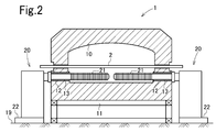
- FIG. 2 is a sectional view taken along line II-II in FIG. It is sectional drawing of the baking furnace which concerns on another embodiment.
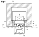
- FIG. 5 is a cross-sectional view taken along line VV in FIG. 4.
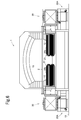
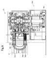
- FIG. 9 is a sectional view taken along line IX-IX in FIG. 8.
- FIG. 1 and 2 show a firing furnace according to an embodiment of the present invention.
- This firing furnace is a roller hearth kiln 1, and a large number of rollers 2 are arranged horizontally, in parallel and at the same height so that a fired article such as a tile raw material is conveyed above the roller group. It is configured.
- a pre-tropical zone 3 Inside the roller hearth kiln 1 is a pre-tropical zone 3, a firing zone 4, and a cooling zone 5 from the entrance side.
- a plurality of burners 6 are installed in the firing zone 4.
- the burner 6 may be provided in a kiln ceiling part, and may be provided in a side wall part.
- a cooling air supply port 7 is provided in the cooling zone 5, and an exhaust port 8 is provided closer to the firing zone 4 than the supply port 7.
- a plurality of exhaust ports 8 may be provided.
- an exhaust port 9 is provided on the kiln entrance side, but exhaust may be performed from the kiln entrance.
- the furnace body 10 of this roller hearth kiln 1 is installed on a gantry 11.
- Each roller 2 penetrates the left and right side walls of the furnace body 10, and both ends thereof are supported by bearing members (not shown) and are rotated around the axis of each roller 2 by a rotation drive device (not shown). Is done.
- the roller 2 is made of a high heat resistant ceramic material such as alumina, but is not limited thereto.
- the Stirling engine 20 is installed so that the high temperature side heat exchange part 21 is inserted under the roller 2 of the cooling zone 5.
- the Stirling engine 20 is disposed on both the left and right sides of the furnace body 10, and the heat exchanging portion 21 extends from the left and right side walls to the vicinity of the central portion in the left and right direction of the furnace body 10.
- through holes 12 are provided in the left and right side walls of the furnace body 10, and the high temperature side heat exchange section 21 is inserted into the furnace through the through holes 12.
- a fireproof heat insulating fiber 13 such as rock wool is filled in order to reduce the propagation of vibration of the Stirling engine 20 to the furnace body 10. Has been.
- the Stirling engine 20 has its machine base 22 fixed to the floor 19 of the factory. Although the furnace body 10 of the roller hearth kiln 1 expands and contracts in the longitudinal direction of the furnace body due to thermal expansion, a refractory heat insulating fiber 13 is filled between the inner peripheral surface of the through hole 12 and the outer peripheral surface of the Stirling engine insertion portion. Therefore, even if the Stirling engine 20 is fixed to the floor 19, the expansion and contraction of the furnace body 10 is not restricted by the Stirling engine 20. Further, the presence of the refractory heat insulating fiber 13 prevents the vibration of the Stirling engine 20 from propagating to the furnace body 10.
- a plurality of Stirling engines 20 are arranged on the firing zone 4 side with respect to the portion where the air supply port 7 is installed.
- the number and position of the Stirling engines 20 are preferably selected so as to have an optimal cooling curve (temperature distribution in the cooling zone in the furnace).
- the low temperature side heat exchange part of the Stirling engine 20 is naturally arranged outside the furnace.
- the cold heat source of the low temperature side heat exchanging section is industrial water. However, when a large amount of cold water is obtained, cold water may be used as the cold heat source, or other low temperature fluid may be used. .
- a fired object such as a tile is transported from the left side to the right side of FIG. 1 by the roller 2, preheated in the pretropical zone 3, fired in the firing zone 4, and cooled. It is cooled in the belt 5 and sent out of the furnace body 10.
- fuel and air are supplied to the burner 6, and the object to be fired is fired by high-temperature combustion gas.
- the maximum temperature of the firing zone 4 is, for example, about 1100 to 1250 ° C.
- the lower limit temperature of the firing zone 4 is about 900 to 1050 ° C.
- An induction fan (attracting exhaust fan) is connected to the exhaust port 9 of the pre-tropical zone 3 through a duct, and almost all of the exhaust gas from the firing zone 4 flows into the pre-tropical region 3 to preheat the object to be fired. It is discharged from the chimney through the exhaust port 9, the duct and the exhaust gas treatment facility. The fired product that has passed through the firing zone 4 is cooled in the cooling zone 5 and falls in temperature.
- the retained heat and radiant heat of the gas in the cooling zone 5 are absorbed by the high temperature side heat exchanging portion 21 of the Stirling engine 20, the Stirling engine 20 is driven, and power is generated by the generator connected to the Stirling engine 20. In this way, the exhaust heat energy of the roller hearth kiln 1 can be recovered as electric power. If necessary, cooling air is supplied from the supply port 7 and high-temperature air is discharged from the exhaust port 8. This high-temperature air is guided to the chimney after exchanging heat with the combustion air to the burner 6.
- the high temperature side heat exchanging section 21 is installed in a zone where the temperature is 800 ° C. or less in the cooling zone 5. At 800 ° C. or lower, tile glaze and the like are in a solid state, so that even if the vibration of Stirling engine 20 propagates to the fired product, the product appearance of the fired product is prevented or suppressed.
- the Stirling engine is preferably installed in the cooling zone 5 where the temperature is 300 ° C. or higher, particularly 500 ° C. or higher.
- the fired product is cooled exclusively by the air supplied from the supply port 7, but in this embodiment, the heat is absorbed by the Stirling engine 20, so the supply port The amount of air supplied from the air supply 7 can be reduced. In some cases, the air supply from the supply port 7 can be stopped. Further, when the fired product is cooled by the endothermic heat of the Stirling engine 20, it is possible to prevent the fired product from being rapidly cooled as compared with the case where the fired product is cooled only by air supply from the supply port 7. Is also prevented.
- the high temperature side heat exchanging portion 21 of the Stirling engine 20 is arranged in the cooling zone 5. Since the combustion exhaust gas from the firing zone 4 hardly flows into the cooling zone 5, there is no fear that the high temperature side heat exchange section 21 is corroded by the combustion exhaust gas, and the Stirling engine 20 can be stably operated over a long period of time.
- the dust or the like that adheres to and accumulates on the high temperature side heat exchanging portion 21 falls and adheres to the object to be fired (product). There is nothing to do.
- the high temperature side heat exchange part of the Stirling engine 20 is inserted into the lower side of the roller 2 from the left and right side walls of the furnace body 10, and the exhaust gas holding heat, radiant heat, etc. from a wide range of the lower side space of the roller 2.
- the exhaust heat energy can be recovered.
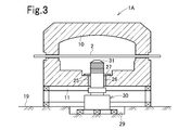
- the high temperature side heat exchanging portion 31 of the Stirling engine 30 may be inserted into the lower space of the roller 2 from the bottom of the furnace body 10 as shown in FIG.
- a through hole 25 is provided in the bottom surface portion of the furnace body 10, and the high temperature side heat exchange unit 31 is inserted into the furnace through the through hole 25.
- a fireproof and heat insulating fiber 26 is filled.
- the upper surface side of the filling layer of the refractory heat insulating fiber 26 is covered with a ceramic plate 27.
- a recess 29 is provided in the floor 19 of the factory, and the Stirling engine 30 is installed.
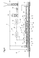
- 20 a is an expansion space of the Stirling engine 20.
- Reference numeral 20 b denotes a heater tube
- 20 c denotes a heater, which constitutes the high temperature side heat exchanging unit 21.
- 20d is a regenerator
- 20e is a cooler
- 20f is a displacer
- 20g is a compression space
- 20h is a power piston
- 20i is a buffer space
- 20p bypass piping
- 20j represents a cooling water inlet (or outlet)
- 20k represents a cooling water outlet (or inlet).
- 20m is a cooling water inlet of the generator 20A
- 20n is a cooling water outlet of the generator 20A
- 20r is a stator core
- 20s is a rotor core.
- FIG. 4 is a cross-sectional view schematically showing a cart type tunnel kiln 40 according to an embodiment of the present invention
- FIG. 5 is a cross-sectional view taken along line VV of FIG.
- An entrance replacement chamber 44 is connected to the entrance side of the furnace body 42 of the cart type tunnel kiln 40 and an exit replacement chamber 47 is connected to the exit side.
- the furnace body 42 is pre-tropical in order along the traveling direction of the carriage. 46, a firing zone 48, and a cooling zone 50 are provided.
- the pre-tropical zone 46 and the firing zone 48 are provided with a muffle 56 that partitions the internal space of the furnace body 42 into a heating region 52 and a heat treatment region 54.
- a plurality of heaters H are installed in the pre-tropical zone 46 of the heating area 52 and a plurality of burners B are installed in the firing zone 48, so that the object to be heated M is indirectly heated via the muffle 56. ing.
- a rail 58 for trolley traveling is laid on the floor of the furnace body 42.
- the heated object M loaded on the trolley D is heated by moving a plurality of trolleys D in the furnace body 42 as a trolley train connected in the furnace length direction. ing.
- Shield plates 62 are attached to the left and right side edges of the carriage D over the entire length of the carriage.
- a receiving rod 64 is extended from the inlet to the left and right sides of the furnace wall 42a in the furnace body 42, and the receiving rod 64 is filled with seal sand.
- the tip of the shielding plate 62 sinks into the sand seal and moves in the furnace. This prevents the air from flowing into the lower part of the carriage and the entry of cooling air, which will be described later, into the furnace.
- the front and rear edges of the carriage D are fitted with adjacent carriages so as to prevent the hot air in the furnace from flowing into the lower part of the carriage and the entry of cooling air into the furnace (see FIG. (Not shown) is formed. Further, cooling air is introduced into the lower portion of the carriage D to prevent the wheels and the carriage frame from being deformed or melted.
- the muffle 56 is formed of a heat resistant metal plate such as stainless steel in a channel shape having a concave cross section, and accommodates a plurality of carriages having the above-described configuration as a carriage train. For this reason, the muffle 56 forms a heat treatment region 54 that is substantially sealed between the hearth 60 and the upper surface of the carriage D, and at the same time forms a heating region 52 between the furnace wall 42 a of the furnace body 42 and the muffle 56.
- the heat treatment region 54 communicates with the cooling space of the cooling zone 50.
- Symbols P and Q are units constituting the furnace body.
- the first exhaust path I mainly includes in-muffle exhaust passages 72 and 74 that open to the heat treatment region 54, a cooling zone exhaust passage 68, and exhaust gas treatment devices 82 and 84.
- Heating region 54 and the preheating region 54a corresponding to the preheat zone 46 which consists of the firing region 54b corresponding to the firing zone 48, evaporant G 1 generated from the heated object M in the preheating region 54a in the arrow A
- the harmful substances in the evaporated product G 1 are burned by the first exhaust gas treatment device 82.
- the firing evaporant G 2 generated from the object to be heated M in region 54b is fluidized along the arrow b, the second muffle the exhaust passage 54 provided on the hot side of the firing region 54b (near the cooling zone 50) harmful substances in the evaporant G 2 is introduced into the second exhaust gas treating apparatus 84 through is adapted to be combusted.
- the exhaust gas treatment apparatus 82 and 84 is an exhaust gas treatment apparatus of the direct combustion type, or decompose harmful substances than 800 ° C. high temperatures, such as dioxins and unburned carbon monoxide gas in the evaporant G 1 Or, it is an apparatus for detoxifying as a stable oxide by burning.
- the first exhaust gas treatment device 82 and the second exhaust gas treatment device 84 are connected in series by an exhaust passage 92. Therefore, the evaporants G 1 and G 2 treated by the second exhaust gas treatment device 84 are completely incinerated, and are made harmless by removing the ash with a dust collector 86 such as a bag filter or a cyclone. Only exhaust gas (for example, moisture or carbon dioxide) can be discharged from the chimney 88 to the outside.
- a dust collector 86 such as a bag filter or a cyclone. Only exhaust gas (for example, moisture or carbon dioxide) can be discharged from the chimney 88 to the outside.
- the object to be heated M is indirectly heated via the muffle 56 by the heater H in the pre-tropical zone 46 and by the burner B in the calcining zone 48 while being loaded on the carriage D and moving through the heat treatment region 54.
- the evaporant contained in the article to be heated M increases in evaporation amount as the temperature rises and fills the preheating region 54a. Since the first muffle the exhaust passage 72 is open to the high temperature portion of the preheating region 54a, it is possible to feed the evaporant G 1 are efficiently collected into the first exhaust gas treatment device 82. Most of the vapors G 1 is processed by the first exhaust gas treatment device 82 occurs while the object to be heated M is moved preheating region 54a.
- the evaporant that does not generate (evaporate) unless it is higher than the preheating temperature is generated in the firing region 54b, but is not trapped in the first muffle exhaust passage 72 and enters the firing region 54b from the preheating region 54a.
- the majority are harmless or oxidized or decomposed in the firing region 54b.
- the amount of the evaporated G 2 fed to the second exhaust gas treatment device 84 through the second muffle exhaust passage 74 provided in the high temperature portion of the firing region 54b is small and a considerable amount is made harmless. Therefore, the second exhaust gas treatment device 84 may be simple and have a small capacity.
- cooling zone 50 provided with the evaporant G 2 entering from the firing region 54b to the cooling space without being caught by the second muffle the exhaust passage 74 to the hot side of the cooling zone 50 together with the cooling air (arrow c) You may make it introduce
- the second exhaust path II is mainly composed of exhaust passages 76 and 78 that open to the heating region 52.
- Exhaust gas g 1 (only heated air) generated in the pre-tropical zone 46 of the heating region 52 is sucked by the blower 90 through the exhaust passage 76 opened to the low temperature side (near the inlet) of the heating region 52 and is discharged from the chimney 88. Discharge.
- the combustion gas g 2 generated in the calcining zone 48 of the heating zone 52 is similarly discharged from the chimney 88 via the exhaust passage 78 provided in the heating zone 52 on the low temperature side (near the pre-tropical zone) of the calcining zone 48.
- one or a plurality of Stirling engines 30 are installed in the cooling zone 50 at intervals in the longitudinal direction.
- a through hole 102 is provided in the bottom plate 100 of the furnace body 42, and the high temperature side heat exchange unit 31 is inserted into the furnace through the through hole 102.
- a refractory heat insulating fiber 104 is filled.
- the Stirling engine 30 is installed by providing a recess 112 in the floor 110 of the factory.
- the above embodiment is an example of the present invention, and the present invention may be other than illustrated.
- the present invention can be used in a firing furnace for firing various products other than tiles.
- the high temperature side heat exchange part of a Stirling engine may be arrange
- the present invention can also be applied to continuous firing furnaces other than tunnel kilns and roller hearth kilns such as shuttle kilns.
- the generator is driven by the Stirling engine.
- the generator may be used for driving a rotating device such as a pump or a compressor.
Landscapes
- Engineering & Computer Science (AREA)
- Mechanical Engineering (AREA)
- General Engineering & Computer Science (AREA)
- Environmental & Geological Engineering (AREA)
- Waste-Gas Treatment And Other Accessory Devices For Furnaces (AREA)
- Tunnel Furnaces (AREA)
Abstract
長期にわたりスターリングエンジンによって排熱エネルギーを安定して回収することができる焼成炉。ローラーハースキルン1の冷却帯5にスターリングエンジン20が設置されている。炉体10の左右側壁に設けた貫通孔12を通してスターリングエンジン20の高温側熱交換部21がローラー2の下側に差し込まれている。スターリングエンジン20によって発電機を駆動し、排熱エネルギーを電力として回収する。
Description
本発明は、タイル等の窯業製品を焼成するのに好適な焼成炉に係り、特にスターリングエンジンにより排熱エネルギーを回収するように構成された焼成炉に関する。
スターリングエンジンによって炉の排熱エネルギーを回収するものとして、特許文献1には溶融炉の排ガスダクトにスターリングエンジンの高温側熱交換部を配置することが記載されている。また、特許文献2には、アルミニウム溶解炉の溶解室の雰囲気に高温側熱交換部を晒すようにスターリングエンジンを配置することが記載されている。
上記特許文献1,2のように、スターリングエンジンの高温側熱交換部を炉の排ガスダクトや、溶解室に、高温燃焼ガス雰囲気に晒すように設置して排熱エネルギーの回収を行う場合、燃焼ガスは腐食性成分(例えば硫黄酸化物や、溶融又は半溶融状態の飛灰粒子、アルカリ金属酸化物の蒸気など)を多く含んでおり、熱交換部が早期に腐食する。また、ダクト内のガス温度は通常は300℃以下であり、このダクトにスターリングエンジンを配置しても排熱エネルギーを効率よく回収することはできない。
本発明は、長期にわたりスターリングエンジンによって排熱エネルギーを安定して回収することができる焼成炉を提供することを目的とする。
本発明の焼成炉は、予熱帯、焼成帯、冷却帯及びスターリングエンジンを有し、スターリングエンジンの高温側の熱交換部が前記冷却帯に配置されている。
該焼成炉としてはローラーハースキルン、トンネルキルン、シャトルキルンなどが好適である。
該ローラーハースキルンの熱交換部は、ローラーの下側に配置されることが好ましい。
前記熱交換部は、炉体に設けられた貫通孔を通って炉内に差し込まれることが好ましい。この場合、貫通孔とスターリングエンジンとの間に振動吸収性を有した耐火性断熱材(例えば耐火断熱繊維)を介在させることが望ましい。
前記熱交換部は、雰囲気温度が300~800℃の帯域に設置されることが好ましい。
本発明の焼成炉は、スターリングエンジンの高温側熱交換部を冷却帯に配置し、排熱エネルギーを例えば電力として回収するものである。この冷却帯は、焼成帯に続くものであるが、被焼成物の冷却を行うために大気が供給されるので、焼成帯から燃焼排ガスは全く又は殆ど流れ込まない。そのため、スターリングエンジンの熱交換部が高温の腐食性燃焼排ガスと接触することはなく、熱交換部の腐食が防止され、長期にわたって安定して排熱エネルギーを回収することができる。また、CO2排出量削減にも寄与する。
本発明は、特にローラーハースキルンに適用するのに好適である。ローラーハースキルンは、多数のローラーを水平に配列し、被焼成物はローラーの上を搬送され、この間に焼成されるように構成されている。このローラーハースキルンは、ローラーの上側及び下側にスペースがあいており、このスペースはスターリングエンジンの熱交換部を配置するのに好適である。
この熱交換部をローラーハースキルンのローラーの下側に配置すると、熱交換部に付着堆積したダスト成分が落下しても被焼成物(製品)上に落下することがなく、不良品発生を防止することができる。
熱交換部をローラーハースキルンの側壁を通してローラー下側に差し込んだ場合、ローラー下側スペースの広い範囲に熱交換部を配置することができ、排熱エネルギーを効率よく回収することができる。
なお、従来のローラーハースキルンでは、冷却帯に冷却用空気(いわゆる「打ち込み空気」を供給して被焼成物を冷却していたが、この空気供給により焼成品が急冷されて焼成物に割れ、歪などが生じることがあったが、スターリングエンジンによって熱を吸収する場合、急冷を防止し、降温曲線をなだらかなものとし、焼成された製品の割れ、歪等を防止することもできる。
本発明では、スターリングエンジンの高温側熱交換部を800℃以下、例えば300~800℃の帯域に設置することが好ましい。この理由は次の通りである。タイル等の窯業製品は、800℃よりも高い温度で焼成され、その一部(例えば釉薬層部分)が溶融又は半溶融状態のガラス状となっているので、スターリングエンジンの振動が作用するとこの溶融又は半溶融状態のガラス状部分に不均一な変形が生じるおそれがある。焼成品が800℃よりも低温にまで降温していると、ガラス状部分もガラス転移点以下にまで降温して固体状態となっており、多少の振動が加えられても不均一な変形が生じない。これにより、外観の良好な窯業製品を歩留りよく得ることができる。
以下、本発明について図面を参照してさらに詳細に説明する。図1,2は本発明の実施の形態に係る焼成炉を示すものである。この焼成炉はローラーハースキルン1であり、多数のローラー2が水平、平行かつ同一高さに配列されており、タイル原料の成形体等の被焼成物がローラー群の上側を搬送されるように構成されている。ローラーハースキルン1内は入口側から予熱帯3、焼成帯4、冷却帯5となっている。焼成帯4には複数のバーナー6が設置されている。バーナー6は、キルン天井部に設けられてもよく、側壁部に設けられてもよい。
冷却帯5には冷却用空気の供給口7が設けられるとともに、該供給口7よりも焼成帯4側に排気口8が設けられている。排気口8は複数個設けられてもよい。予熱帯3には、キルン入口側に排気口9が設けられているが、キルン入口から排気してもよい。
図2の通り、このローラーハースキルン1の炉体10は架台11上に設置されている。各ローラー2は炉体10の左右の側壁を貫通しており、その両端が軸受部材(図示略)によって支持されると共に、回転駆動装置(図示略)によって各ローラー2の軸心回りに回転駆動される。ローラー2は、アルミナ等の高耐熱性セラミック材料にて構成されているが、これに限定されない。
冷却帯5のローラー2の下側に高温側熱交換部21を差し込むようにしてスターリングエンジン20が設置されている。この実施の形態では、スターリングエンジン20は炉体10の左右両側に配置されており、熱交換部21は左右の両側壁から炉体10の左右方向中央部近傍にまで延在している。この実施の形態では、炉体10の左右の側壁にそれぞれ貫通孔12が設けられ、この貫通孔12を通して高温側熱交換部21が炉内に挿入されている。貫通孔12の内周面とスターリングエンジン差込部外周面との間には、スターリングエンジン20の振動が炉体10に伝播することを緩和するために、ロックウール等の耐火断熱繊維13が充填されている。
スターリングエンジン20は、そのマシンベース22が工場の床19に固定されている。なお、ローラーハースキルン1の炉体10は熱膨張によって炉体長手方向に伸縮するが、貫通孔12の内周面とスターリングエンジン差込部外周面との間に耐火断熱繊維13を充填してあるので、スターリングエンジン20が床19に固定されていても、炉体10の伸縮はスターリングエンジン20に拘束されない。また、耐火断熱繊維13を介在させたことにより、スターリングエンジン20の振動が炉体10に伝播することも抑制される。
スターリングエンジン20は、空気供給口7を設置した部分よりも焼成帯4側に間隔をおいて複数台配置されている。スターリングエンジン20の設置台数及び位置は、最適な冷却曲線(炉内の冷却帯の温度分布)となるように選定されるのが好ましい。スターリングエンジン20の低温側熱交換部は当然ながら炉外に配置されている。この実施の形態では、低温側熱交換部の冷熱源は工業用水となっているが、大量の冷水が得られる場合には冷水を冷熱源としてもよく、またその他の低温流体を用いてもよい。
このように構成されたローラーハースキルン1においては、タイル等の被焼成物はローラー2によって図1の左側から右側に向って搬送され、予熱帯3で予熱され、焼成帯4で焼成され、冷却帯5で冷却され、炉体10外に送り出される。焼成帯4では、バーナー6に燃料及び空気が供給され、高温の燃焼ガスによって被焼成物が焼成される。被焼成物がタイルの場合、焼成帯4の最高温度は例えば1100~1250℃程度とされる。焼成帯4の下限温度は900~1050℃程度である。
前記予熱帯3の排気口9にダクトを介してインダクションファン(誘引排風機)が接続されており、焼成帯4からの排ガスのほぼ全量が予熱帯3に流れ込み、被焼成物を予熱した後、排気口9、ダクト及び排ガス処理設備を介して煙突から排出される。焼成帯4を通った焼成品は、冷却帯5において冷却されて降温する。
この冷却帯5内のガスの保有熱や輻射熱がスターリングエンジン20の高温側熱交換部21に吸収され、スターリングエンジン20が駆動し、スターリングエンジン20に接続された発電機によって発電が行われる。このようにしてローラーハースキルン1の排熱エネルギーを電力として回収することができる。なお、必要に応じ、供給口7から冷却用空気を供給し、排気口8から高温空気を排出する。この高温空気は、バーナー6への燃焼用空気と熱交換した後、煙突へ導かれる。
この実施の形態では、高温側熱交換部21は冷却帯5のうちでも温度が800℃以下となる帯域に設置されている。800℃以下では、タイル釉薬等も固体状態となっているので、スターリングエンジン20の振動が焼成品に伝播しても焼成品の製品外観が損なわれることが防止ないし抑制される。
スターリングエンジンは冷却帯5のうち温度が300℃以上特に500℃以上の帯域に設置されるのが好ましい。なお、従来の焼成炉の冷却帯では、専ら供給口7から供給される空気によって焼成品の冷却が行われていたが、この実施の形態では、スターリングエンジン20によって熱を吸収するので、供給口7からの空気供給量を減少させることができ、場合によっては供給口7からの空気供給を停止することも可能である。また、このスターリングエンジン20の吸熱によって焼成品を冷却する場合、供給口7からの空気供給のみによって冷却を行う場合に比べて焼成品の急激な冷却を防止することができ、製品の割れや歪も防止される。
冷却用空気を吹き込まない場合、スターリングエンジン20によってより多くの排熱を回収することができる。なお、この実施の形態のように複数のスターリングエンジン20を冷却帯の長手方向に配列設置した場合、各スターリングエンジンの排熱回収量を制御することにより冷却帯の温度分布を制御することも可能である。
このローラーハースキルン1では、冷却帯5にスターリングエンジン20の高温側熱交換部21を配置している。この冷却帯5には焼成帯4からの燃焼排ガスが殆ど流れ込まないので、燃焼排ガスによって高温側熱交換部21が腐食するおそれがなく、スターリングエンジン20を長期にわたって安定して運転することができる。
この実施の形態では、高温側熱交換部21をローラー2の下側に配置しているので、高温側熱交換部21に付着、堆積したダスト等が落下して被焼成物(製品)に付着することがない。
この実施の形態では、スターリングエンジン20の高温側熱交換部を炉体10の左右両側壁からローラー2の下側に差し込んでおり、ローラー2の下側スペースの広い範囲から排ガス保有熱や輻射熱などの排熱エネルギーを回収することができる。
ただし、本発明では、図3のように炉体10の底部からスターリングエンジン30の高温側熱交換部31をローラー2の下側スペースに差し込んでもよい。図3のローラーハースキルン1Aでは、炉体10の底面部に貫通孔25が設けられ、この貫通孔25を通して高温側熱交換部31が炉内に差し込まれている。スターリングエンジン30の差込部と貫通孔25の内周面との間には、耐火断熱繊維26が充填されている。この耐火断熱繊維26の充填層の上面側はセラミックプレート27で覆われている。この実施の形態では、工場の床19に凹所29を設けてスターリングエンジン30を設置している。このように、キルン底面を貫通させて、スターリングエンジンを設置することは、既設のキルンに対しても容易に適用することができる。
図6~図9にスターリングエンジン設置部付近の詳細な構成の一例を示す。20aはスターリングエンジン20の膨張空間である。20bはヒータ管、20cはヒータであり、高温側熱交換部21を構成している。20dは再生器、20eはクーラ、20fはディスプレーサ、20gは圧縮空間、20hはパワーピストン、20iはバッファ空間、20pのバイパス配管を示す。20jは冷却水入口(又は出口)、20kは冷却水出口(又は入口)を示す。20mは発電機20Aの冷却水入口、20nは発電機20Aの冷却水出口、20rは固定子鉄心、20sは回転子鉄心を示す。
図4は、本発明の実施の形態に係わる台車式トンネルキルン40を模式的に示す断面図、図5は図4のV-V線断面図である。
台車式トンネルキルン40の炉本体42の入口側には入口置換室44が、また、出口側には出口置換室47が接続されており、炉本体42は台車の進行方向に沿って順に予熱帯46、焼成帯48、冷却帯50が設けられている。予熱帯46と焼成帯48には炉本体42の内部空間を加熱領域52と加熱処理領域54とに区画するマッフル56が設けられている。加熱領域52の予熱帯46には複数個のヒータHが、また、焼成帯48には複数個のバーナBが設置されており、被加熱物Mをマッフル56を介して間接加熱するようになっている。
炉本体42の床部には台車走行用のレール58が敷設されている。この台車式トンネル炉40では、複数台の台車Dを炉長方向に連なった台車列として炉本体42内を移動させることにより、台車D上に積載した被加熱物Mを加熱処理するようになっている。
台車Dの左右の両側縁部には遮蔽板62が台車の全長にわたって付設されている。一方、炉本体42には受け樋64が炉壁42aの左右両側に入口から出口まで延設されており、受け樋64にはシールサンドが満たされている。台車Dが炉本体42に装入されると遮蔽板62の先端がサンドシールの中に沈潜して炉内を移動することになるので、遮蔽板62は炉内の熱気が台車Dの側縁部から台車の下部へ流入することと、後述する冷却空気の炉内への侵入を防止している。また、台車Dの前後の縁部には隣接する台車と嵌合して炉内の熱気が台車の下部へ流入することと、冷却空気の炉内への侵入とを防止する当接部(図示せず)が形成されている。さらに台車Dの下部には冷却用の空気が導入されて車輪や台車フレームの変形や溶損を防止するようになっている。
マッフル56はステンレスなどの耐熱性金属板で断面凹型のチャンネル状に形成されており、上記のような構成を有する複数台の台車を台車列として収容している。このためマッフル56は炉床60と台車Dの上面とでほぼ密閉された加熱処理領域54を形成すると同時に、炉本体42の炉壁42aとマッフル56との間に加熱領域52を形成する。なお、加熱処理領域54は冷却帯50の冷却空間に連通している。記号P,Qは炉体を構成するユニットである。
次に各領域で発生する蒸発物などの排気経路について説明する。
第1の排気経路Iは、主として加熱処理領域54に開口するマッフル内排気通路72、74および冷却帯排気通路68、排ガス処理装置82、84とから構成されている。加熱処理領域54は予熱帯46に対応する予熱領域54aと、焼成帯48に対応する焼成領域54bとからなっており、予熱領域54aで被加熱物Mから発生する蒸発物G1は矢印アに沿って流動し、予熱領域54aの高温側(焼成帯48の近傍)に設けた第1のマッフル内排気通路72を通って第1の排ガス処理装置82へ導入される。そして蒸発物G1中の有害物質は第1の排ガス処理装置82で燃焼処理される。また、焼成領域54bで被加熱物Mから発生する蒸発物G2は矢印イに沿って流動し、焼成領域54bの高温側(冷却帯50の近傍)に設けた第2のマッフル内排気通路54を介して第2の排ガス処理装置84へ導入されて蒸発物G2中の有害物質が燃焼処理されるようになっている。
ここで、排ガス処理装置82、84は、直接燃焼タイプの排ガス処理装置であり、蒸発物G1中のダイオキシンや未燃焼の一酸化炭素ガスなどの有害物質を800℃以上の高温で分解したり、あるいは燃焼させて安定した酸化物などとして無害化する装置である。
第1の排ガス処理装置82と第2の排ガス処理装置84とは排気通路92によって直列に連通されている。従って、第2の排ガス処理装置84で処理された蒸発物G1とG2とは完全に灰化しており、バグフィルタあるいはサイクロンなどの集塵装置86で灰分を除去することにより、無害化された排気(例えば、水分や炭酸ガス)のみを煙突88から外部へ放出することができる。
被加熱物Mは台車Dに積載されてこの加熱処理領域54を移動する間に予熱帯46ではヒータHにより、また、焼成帯48ではバーナBによりマッフル56を介して間接的に加熱される。被加熱物Mに含有される蒸発物は、温度の上昇に伴って蒸発量を増し予熱領域54a内に充満する。第1のマッフル内排気通路72は予熱領域54aの高温部に開口しているので、蒸発物G1を効率よく捕集して第1の排ガス処理装置82へ送給することができる。蒸発物G1の大半は被加熱物Mが予熱領域54aを移動する間に発生して第1の排ガス処理装置82で処理される。また、予熱温度よりも更に高温でなければ発生(蒸発)しない蒸発物は焼成領域54bで発生するが、第1のマッフル内排気通路72で捕捉されずに予熱領域54aから焼成領域54bへ侵入した蒸発物G1とともに、その大半は焼成領域54bで分解したり酸化したりして無害化される。このように焼成領域54bの高温部に設けた第2のマッフル内排気通路74を通って第2の排ガス処理装置84へ送給される蒸発物G2は少量でありかつ相当量が無害化されているので、第2の排ガス処理装置84は簡便で小容量のものでよい。
なお、冷却帯50では、第2のマッフル内排気通路74で捕捉されずに焼成領域54bから冷却空間へ侵入した蒸発物G2を冷却空気(矢印ウ)とともに冷却帯50の高温側に設けた排気通路68から第2の排ガス処理装置84へ導入するようにしてもよい。このような排気経路とすることで蒸発物をより完全に処理することができる。
第2の排気経路IIは、主として加熱領域52に開口している排気通路76、78から構成されている。加熱領域52の予熱帯46で発生する排気ガスg1(加熱空気のみ)は加熱領域52の低温側(入口近傍)に開口している排気通路76を介してブロワ90で吸引して煙突88から排出する。また、加熱領域52の焼成帯48で発生する燃焼ガスg2は、焼成帯48の低温側(予熱帯近傍)の加熱領域52に設けた排気通路78を介して同様に煙突88から排出する。
このトンネルキルン40では、冷却帯50に、1台又は長手方向に間隔をおいて複数台のスターリングエンジン30が設置されている。この実施の形態では、炉体42の底版100に貫通孔102が設けられ、この貫通孔102を通して高温側熱交換部31が炉内に差し込まれている。スターリングエンジン30の差込部と貫通孔102の内周面との間には、耐火断熱繊維104が充填されている。この実施の形態では、工場の床110に凹所112を設けてスターリングエンジン30を設置している。
上記実施の形態は本発明の一例であり、本発明は図示以外の形態とされてもよい。本発明はタイル以外の各種被焼成物の焼成用の焼成炉に利用することができる。また、スターリングエンジンの高温側熱交換部は図示以外の箇所に配置されてもよい。
本発明は、シャトルキルンなど、トンネルキルン及びローラーハースキルン以外の連続式焼成炉にも適用することができる。上記実施の形態では、スターリングエンジンによって発電機を駆動しているが、ポンプやコンプレッサーなどの回転機器の駆動に用いてもよい。
本発明を特定の態様を用いて詳細に説明したが、本発明の意図と範囲を離れることなく様々な変更が可能であることは当業者に明らかである。
なお、本出願は、2011年12月22日付で出願された日本特許出願(特願2011-281581)に基づいており、その全体が引用により援用される。
なお、本出願は、2011年12月22日付で出願された日本特許出願(特願2011-281581)に基づいており、その全体が引用により援用される。
Claims (9)
- 予熱帯、焼成帯及び冷却帯を有する焼成炉において、スターリングエンジンを、その高温側の熱交換部を前記冷却帯に配置させて設置したことを特徴とする焼成炉。
- 請求項1において、該焼成炉はローラーハースキルン、トンネルキルン又はシャトルキルンであることを特徴とする焼成炉。
- 請求項1において、該焼成炉はローラーハースキルンであり、前記熱交換部が該ローラーハースキルンのローラーの下側に配置されていることを特徴とする焼成炉。
- 請求項1において、該焼成炉は、被焼成物を載せて該炉内を移動する台車を有したトンネルキルンであり、前記熱交換部は、該台車の下側に配置されていることを特徴とする焼成炉。
- 請求項1ないし4のいずれか1項において、前記熱交換部が炉体に設けられた貫通孔を通って炉内に差し込まれていることを特徴とする焼成炉。
- 請求項5において、該貫通孔とスターリングエンジンとの間に振動吸収性を有した耐火断熱材を介在させたことを特徴とする焼成炉。
- 請求項1ないし6のいずれか1項において、前記熱交換部は雰囲気温度が300~800℃の帯域に設置されていることを特徴とする焼成炉。
- 請求項1ないし7のいずれか1項において、前記冷却帯は、冷却用空気の吹き込みなしにスターリングエンジンによって冷却が行われることを特徴とする焼成炉。
- 請求項1ないし8のいずれか1項において、複数の前記スターリングエンジンが前記冷却帯の長手方向に配列されていることを特徴とする焼成炉。
Priority Applications (1)
| Application Number | Priority Date | Filing Date | Title |
|---|---|---|---|
| CN201280062643.8A CN103998887A (zh) | 2011-12-22 | 2012-12-17 | 烧成炉 |
Applications Claiming Priority (2)
| Application Number | Priority Date | Filing Date | Title |
|---|---|---|---|
| JP2011281581A JP5862277B2 (ja) | 2011-12-22 | 2011-12-22 | 焼成炉 |
| JP2011-281581 | 2011-12-22 |
Publications (1)
| Publication Number | Publication Date |
|---|---|
| WO2013094553A1 true WO2013094553A1 (ja) | 2013-06-27 |
Family
ID=48668443
Family Applications (1)
| Application Number | Title | Priority Date | Filing Date |
|---|---|---|---|
| PCT/JP2012/082632 Ceased WO2013094553A1 (ja) | 2011-12-22 | 2012-12-17 | 焼成炉 |
Country Status (3)
| Country | Link |
|---|---|
| JP (1) | JP5862277B2 (ja) |
| CN (1) | CN103998887A (ja) |
| WO (1) | WO2013094553A1 (ja) |
Cited By (6)
| Publication number | Priority date | Publication date | Assignee | Title |
|---|---|---|---|---|
| US20160320133A1 (en) * | 2013-12-20 | 2016-11-03 | Cosimo RUSCE | Plant and method for the recovery of heat from a firing kiln |
| CN106949733A (zh) * | 2017-04-20 | 2017-07-14 | 广东中鹏热能科技有限公司 | 一种新型窑炉高温取热方法及其高温取热节能窑炉 |
| CN107314670A (zh) * | 2017-08-15 | 2017-11-03 | 大石桥市宝鼎耐火材料有限公司 | 垂直气流耐火材料烧成隧道窑及其烧成方法 |
| CN108195193A (zh) * | 2018-02-02 | 2018-06-22 | 佛山高砂工业窑炉有限公司 | 一种气密式辊道窑用置换室加热和排水构造 |
| CN112944903A (zh) * | 2021-02-23 | 2021-06-11 | 廖朝鲜 | 循环烧制的装配结构梭式窑系统 |
| CN116254407A (zh) * | 2023-03-21 | 2023-06-13 | 昆明华信金属材料制造有限公司 | 一种风冷式钢带冷却装置 |
Families Citing this family (7)
| Publication number | Priority date | Publication date | Assignee | Title |
|---|---|---|---|---|
| CN104457227B (zh) * | 2014-10-29 | 2016-07-27 | 彭州市半陶陶瓷有限公司 | 一种分体式隧道窑 |
| JP6507006B2 (ja) * | 2015-03-26 | 2019-04-24 | 月島機械株式会社 | 流動層焼却設備 |
| CN105234339B (zh) * | 2015-10-26 | 2017-09-05 | 杭州盈发炉窑科技有限公司 | 一种环保型生物质颗粒锻造炉 |
| CN105403061B (zh) * | 2015-12-14 | 2017-07-25 | 广东摩德娜科技股份有限公司 | 一种循环利用冷却余热提高助燃风温度的节能窑炉 |
| CN105823333A (zh) * | 2016-05-24 | 2016-08-03 | 北京工业大学 | 分段式隧道窑 |
| CN109307412B (zh) * | 2018-09-17 | 2023-09-05 | 湖南星华能源科技服务有限公司 | 一种均匀透风均匀出料防尘节能立式烘焙窑 |
| JP7546807B1 (ja) | 2024-03-25 | 2024-09-06 | ノリタケ株式会社 | 冷却炉 |
Citations (6)
| Publication number | Priority date | Publication date | Assignee | Title |
|---|---|---|---|---|
| JPH0348697U (ja) * | 1989-09-19 | 1991-05-10 | ||
| JPH0443286A (ja) * | 1990-06-06 | 1992-02-13 | Murata Mfg Co Ltd | 連続式焼成炉 |
| JP2001330371A (ja) * | 2000-05-23 | 2001-11-30 | Ngk Insulators Ltd | 連続式焼成炉 |
| JP2002061540A (ja) * | 2000-08-22 | 2002-02-28 | Kangen Yoyu Gijutsu Kenkyusho:Kk | 溶融炉の高温な排ガス系統を利用した直接的発電法 |
| JP2011169255A (ja) * | 2010-02-19 | 2011-09-01 | Gunma-Gohkin Co Ltd | 溶解炉廃熱利用スターリングエンジン発電給湯システム |
| JP2012241200A (ja) * | 2011-05-16 | 2012-12-10 | Nippon Steel Engineering Co Ltd | 炉内熱の利用装置 |
Family Cites Families (11)
| Publication number | Priority date | Publication date | Assignee | Title |
|---|---|---|---|---|
| JPS5810671B2 (ja) * | 1979-10-08 | 1983-02-26 | 高砂工業株式会社 | 燻瓦焼成炉の冷却装置 |
| JPS6086375A (ja) * | 1983-10-15 | 1985-05-15 | 株式会社ノリタケカンパニーリミテド | ロ−ラ−ハ−スキルンの冷却帯に於ける陶磁器製品の急冷方法および装置 |
| JPH04124585A (ja) * | 1990-09-14 | 1992-04-24 | Ngk Insulators Ltd | 連続炉の窒素ガス利用冷却装置 |
| JPH04288478A (ja) * | 1991-03-15 | 1992-10-13 | Murata Mfg Co Ltd | 連続焼成炉 |
| JPH0894050A (ja) * | 1994-09-29 | 1996-04-12 | Hitachi Eng Co Ltd | 排熱利用発電装置 |
| JP2003314364A (ja) * | 2002-04-19 | 2003-11-06 | Katsuhiro Ito | 廃熱利用スターリングエンジン発電装置 |
| JP2003020993A (ja) * | 2002-05-28 | 2003-01-24 | Katsuhiro Ito | 排熱利用組込式熱交換器を用いたスターリングエンジン発電システム |
| JP4210833B2 (ja) * | 2002-10-07 | 2009-01-21 | 光洋サーモシステム株式会社 | 連続焼成炉 |
| JP2010169343A (ja) * | 2009-01-24 | 2010-08-05 | Yuji Ikedo | 往復形熱交換器 |
| CN101556112B (zh) * | 2009-05-21 | 2010-12-29 | 岳阳市巴陵节能炉窑工程有限公司 | 物理热循环利用高温节能隧道窑 |
| CN201583131U (zh) * | 2009-11-09 | 2010-09-15 | 寿阳县明鑫铝矾耐火材料有限公司 | 隧道窑余热利用系统 |
-
2011
- 2011-12-22 JP JP2011281581A patent/JP5862277B2/ja not_active Expired - Fee Related
-
2012
- 2012-12-17 CN CN201280062643.8A patent/CN103998887A/zh active Pending
- 2012-12-17 WO PCT/JP2012/082632 patent/WO2013094553A1/ja not_active Ceased
Patent Citations (6)
| Publication number | Priority date | Publication date | Assignee | Title |
|---|---|---|---|---|
| JPH0348697U (ja) * | 1989-09-19 | 1991-05-10 | ||
| JPH0443286A (ja) * | 1990-06-06 | 1992-02-13 | Murata Mfg Co Ltd | 連続式焼成炉 |
| JP2001330371A (ja) * | 2000-05-23 | 2001-11-30 | Ngk Insulators Ltd | 連続式焼成炉 |
| JP2002061540A (ja) * | 2000-08-22 | 2002-02-28 | Kangen Yoyu Gijutsu Kenkyusho:Kk | 溶融炉の高温な排ガス系統を利用した直接的発電法 |
| JP2011169255A (ja) * | 2010-02-19 | 2011-09-01 | Gunma-Gohkin Co Ltd | 溶解炉廃熱利用スターリングエンジン発電給湯システム |
| JP2012241200A (ja) * | 2011-05-16 | 2012-12-10 | Nippon Steel Engineering Co Ltd | 炉内熱の利用装置 |
Cited By (9)
| Publication number | Priority date | Publication date | Assignee | Title |
|---|---|---|---|---|
| US20160320133A1 (en) * | 2013-12-20 | 2016-11-03 | Cosimo RUSCE | Plant and method for the recovery of heat from a firing kiln |
| CN106949733A (zh) * | 2017-04-20 | 2017-07-14 | 广东中鹏热能科技有限公司 | 一种新型窑炉高温取热方法及其高温取热节能窑炉 |
| CN106949733B (zh) * | 2017-04-20 | 2023-06-06 | 广东中鹏热能科技有限公司 | 一种新型窑炉高温取热方法及其高温取热节能窑炉 |
| CN107314670A (zh) * | 2017-08-15 | 2017-11-03 | 大石桥市宝鼎耐火材料有限公司 | 垂直气流耐火材料烧成隧道窑及其烧成方法 |
| CN108195193A (zh) * | 2018-02-02 | 2018-06-22 | 佛山高砂工业窑炉有限公司 | 一种气密式辊道窑用置换室加热和排水构造 |
| CN108195193B (zh) * | 2018-02-02 | 2024-02-13 | 佛山高砂工业窑炉有限公司 | 一种气密式辊道窑用置换室加热和排水构造 |
| CN112944903A (zh) * | 2021-02-23 | 2021-06-11 | 廖朝鲜 | 循环烧制的装配结构梭式窑系统 |
| CN116254407A (zh) * | 2023-03-21 | 2023-06-13 | 昆明华信金属材料制造有限公司 | 一种风冷式钢带冷却装置 |
| CN116254407B (zh) * | 2023-03-21 | 2024-01-30 | 昆明华信金属材料制造有限公司 | 一种风冷式钢带冷却装置 |
Also Published As
| Publication number | Publication date |
|---|---|
| JP5862277B2 (ja) | 2016-02-16 |
| JP2013130366A (ja) | 2013-07-04 |
| CN103998887A (zh) | 2014-08-20 |
Similar Documents
| Publication | Publication Date | Title |
|---|---|---|
| JP5862277B2 (ja) | 焼成炉 | |
| CN106017072B (zh) | 节能型热风循环隧道窑及隧道窑余热回用方法 | |
| WO2012128172A1 (ja) | セラミック多孔体焼成用トンネルキルン | |
| CN108779959B (zh) | 工业炉及其热利用方法 | |
| JP2002243368A (ja) | 平面ガラス基板用連続式焼成炉 | |
| EP1029625A2 (en) | Muffle convection brazing and annealing system and method | |
| WO2017048323A1 (en) | Multi-hearth roasters for use in metal recycling processes | |
| RU2606671C2 (ru) | Устройство для транспортирования металлургического материала | |
| CN110260650A (zh) | 一种环保型隧道窑 | |
| US4069008A (en) | Method and apparatus for heating a workpiece | |
| JP4387326B2 (ja) | 台車式トンネル炉 | |
| JPH11311484A (ja) | 炉内雰囲気循環型ローラハース式連続焼成炉 | |
| CN202393206U (zh) | 一种新型坑道式折叠轨道连续烧成窑炉 | |
| CN213357638U (zh) | 一种电弧炉三段式废钢预热装置 | |
| JP4465702B2 (ja) | 加熱装置及び加熱方法 | |
| RU2111933C1 (ru) | Способ обжига керамических изделий и устройство для его осуществления | |
| US4846678A (en) | Means and method for heat treatment of green bodies | |
| RU2008101200A (ru) | Способ термической обработки сыпучих материалов в печи шахтного типа и печь для его осуществления | |
| CN112229207A (zh) | 新型气氛保护窑炉 | |
| GB902674A (en) | System for baking carbonaceous products or the like | |
| JPS5941519Y2 (ja) | トンネルキルンの熱回収装置 | |
| EP3027991A2 (en) | A radiating heating module for continuous-cycle firing kilns of ceramic products | |
| RU2015477C1 (ru) | Печь для обжига углеродных изделий | |
| JP2014219139A (ja) | 被加熱材の予熱方法および予熱装置 | |
| JP2013096660A (ja) | 火葬炉 |
Legal Events
| Date | Code | Title | Description |
|---|---|---|---|
| 121 | Ep: the epo has been informed by wipo that ep was designated in this application |
Ref document number: 12859306 Country of ref document: EP Kind code of ref document: A1 |
|
| NENP | Non-entry into the national phase |
Ref country code: DE |
|
| 122 | Ep: pct application non-entry in european phase |
Ref document number: 12859306 Country of ref document: EP Kind code of ref document: A1 |