WO2013094457A1 - 撮影補助光装置およびこれを備えたデジタルカメラ - Google Patents
撮影補助光装置およびこれを備えたデジタルカメラ Download PDFInfo
- Publication number
- WO2013094457A1 WO2013094457A1 PCT/JP2012/081929 JP2012081929W WO2013094457A1 WO 2013094457 A1 WO2013094457 A1 WO 2013094457A1 JP 2012081929 W JP2012081929 W JP 2012081929W WO 2013094457 A1 WO2013094457 A1 WO 2013094457A1
- Authority
- WO
- WIPO (PCT)
- Prior art keywords
- light
- emitting diode
- light emitting
- double layer
- layer capacitor
- Prior art date
- Legal status (The legal status is an assumption and is not a legal conclusion. Google has not performed a legal analysis and makes no representation as to the accuracy of the status listed.)
- Ceased
Links
Images


Classifications
-
- G—PHYSICS
- G03—PHOTOGRAPHY; CINEMATOGRAPHY; ANALOGOUS TECHNIQUES USING WAVES OTHER THAN OPTICAL WAVES; ELECTROGRAPHY; HOLOGRAPHY
- G03B—APPARATUS OR ARRANGEMENTS FOR TAKING PHOTOGRAPHS OR FOR PROJECTING OR VIEWING THEM; APPARATUS OR ARRANGEMENTS EMPLOYING ANALOGOUS TECHNIQUES USING WAVES OTHER THAN OPTICAL WAVES; ACCESSORIES THEREFOR
- G03B7/00—Control of exposure by setting shutters, diaphragms or filters, separately or conjointly
- G03B7/08—Control effected solely on the basis of the response, to the intensity of the light received by the camera, of a built-in light-sensitive device
-
- G—PHYSICS
- G03—PHOTOGRAPHY; CINEMATOGRAPHY; ANALOGOUS TECHNIQUES USING WAVES OTHER THAN OPTICAL WAVES; ELECTROGRAPHY; HOLOGRAPHY
- G03B—APPARATUS OR ARRANGEMENTS FOR TAKING PHOTOGRAPHS OR FOR PROJECTING OR VIEWING THEM; APPARATUS OR ARRANGEMENTS EMPLOYING ANALOGOUS TECHNIQUES USING WAVES OTHER THAN OPTICAL WAVES; ACCESSORIES THEREFOR
- G03B15/00—Special procedures for taking photographs; Apparatus therefor
- G03B15/02—Illuminating scene
- G03B15/03—Combinations of cameras with lighting apparatus; Flash units
- G03B15/05—Combinations of cameras with electronic flash apparatus; Electronic flash units
-
- H—ELECTRICITY
- H04—ELECTRIC COMMUNICATION TECHNIQUE
- H04N—PICTORIAL COMMUNICATION, e.g. TELEVISION
- H04N23/00—Cameras or camera modules comprising electronic image sensors; Control thereof
-
- H—ELECTRICITY
- H04—ELECTRIC COMMUNICATION TECHNIQUE
- H04N—PICTORIAL COMMUNICATION, e.g. TELEVISION
- H04N23/00—Cameras or camera modules comprising electronic image sensors; Control thereof
- H04N23/56—Cameras or camera modules comprising electronic image sensors; Control thereof provided with illuminating means
-
- H—ELECTRICITY
- H04—ELECTRIC COMMUNICATION TECHNIQUE
- H04N—PICTORIAL COMMUNICATION, e.g. TELEVISION
- H04N23/00—Cameras or camera modules comprising electronic image sensors; Control thereof
- H04N23/60—Control of cameras or camera modules
- H04N23/65—Control of camera operation in relation to power supply
-
- H—ELECTRICITY
- H04—ELECTRIC COMMUNICATION TECHNIQUE
- H04N—PICTORIAL COMMUNICATION, e.g. TELEVISION
- H04N23/00—Cameras or camera modules comprising electronic image sensors; Control thereof
- H04N23/60—Control of cameras or camera modules
- H04N23/67—Focus control based on electronic image sensor signals
- H04N23/671—Focus control based on electronic image sensor signals in combination with active ranging signals, e.g. using light or sound signals emitted toward objects
-
- H—ELECTRICITY
- H04—ELECTRIC COMMUNICATION TECHNIQUE
- H04N—PICTORIAL COMMUNICATION, e.g. TELEVISION
- H04N23/00—Cameras or camera modules comprising electronic image sensors; Control thereof
- H04N23/60—Control of cameras or camera modules
- H04N23/69—Control of means for changing angle of the field of view, e.g. optical zoom objectives or electronic zooming
-
- H—ELECTRICITY
- H04—ELECTRIC COMMUNICATION TECHNIQUE
- H04N—PICTORIAL COMMUNICATION, e.g. TELEVISION
- H04N23/00—Cameras or camera modules comprising electronic image sensors; Control thereof
- H04N23/70—Circuitry for compensating brightness variation in the scene
- H04N23/74—Circuitry for compensating brightness variation in the scene by influencing the scene brightness using illuminating means
-
- H—ELECTRICITY
- H05—ELECTRIC TECHNIQUES NOT OTHERWISE PROVIDED FOR
- H05B—ELECTRIC HEATING; ELECTRIC LIGHT SOURCES NOT OTHERWISE PROVIDED FOR; CIRCUIT ARRANGEMENTS FOR ELECTRIC LIGHT SOURCES, IN GENERAL
- H05B45/00—Circuit arrangements for operating light-emitting diodes [LED]
- H05B45/10—Controlling the intensity of the light
- H05B45/12—Controlling the intensity of the light using optical feedback
-
- G—PHYSICS
- G03—PHOTOGRAPHY; CINEMATOGRAPHY; ANALOGOUS TECHNIQUES USING WAVES OTHER THAN OPTICAL WAVES; ELECTROGRAPHY; HOLOGRAPHY
- G03B—APPARATUS OR ARRANGEMENTS FOR TAKING PHOTOGRAPHS OR FOR PROJECTING OR VIEWING THEM; APPARATUS OR ARRANGEMENTS EMPLOYING ANALOGOUS TECHNIQUES USING WAVES OTHER THAN OPTICAL WAVES; ACCESSORIES THEREFOR
- G03B17/00—Details of cameras or camera bodies; Accessories therefor
- G03B17/18—Signals indicating condition of a camera member or suitability of light
-
- G—PHYSICS
- G03—PHOTOGRAPHY; CINEMATOGRAPHY; ANALOGOUS TECHNIQUES USING WAVES OTHER THAN OPTICAL WAVES; ELECTROGRAPHY; HOLOGRAPHY
- G03B—APPARATUS OR ARRANGEMENTS FOR TAKING PHOTOGRAPHS OR FOR PROJECTING OR VIEWING THEM; APPARATUS OR ARRANGEMENTS EMPLOYING ANALOGOUS TECHNIQUES USING WAVES OTHER THAN OPTICAL WAVES; ACCESSORIES THEREFOR
- G03B2215/00—Special procedures for taking photographs; Apparatus therefor
- G03B2215/05—Combinations of cameras with electronic flash units
- G03B2215/0564—Combinations of cameras with electronic flash units characterised by the type of light source
- G03B2215/0567—Solid-state light source, e.g. LED, laser
-
- G—PHYSICS
- G03—PHOTOGRAPHY; CINEMATOGRAPHY; ANALOGOUS TECHNIQUES USING WAVES OTHER THAN OPTICAL WAVES; ELECTROGRAPHY; HOLOGRAPHY
- G03B—APPARATUS OR ARRANGEMENTS FOR TAKING PHOTOGRAPHS OR FOR PROJECTING OR VIEWING THEM; APPARATUS OR ARRANGEMENTS EMPLOYING ANALOGOUS TECHNIQUES USING WAVES OTHER THAN OPTICAL WAVES; ACCESSORIES THEREFOR
- G03B2215/00—Special procedures for taking photographs; Apparatus therefor
- G03B2215/05—Combinations of cameras with electronic flash units
- G03B2215/0564—Combinations of cameras with electronic flash units characterised by the type of light source
- G03B2215/0575—Ring shaped lighting arrangements
Definitions
- the present invention provides a photographing auxiliary light device having a light emitting diode, an electric double layer capacitor for supplying power to the light emitting diode, and a nonvolatile memory storing light emission color information of the light emitting diode. This facilitates management of important colors in auxiliary light photography.
- the photographing auxiliary light device includes a plurality of light emitting diodes, and the plurality of light emitting diodes include light emitting diodes having different light distributions. Accordingly, the light distribution of the photographing auxiliary light device can be changed by selecting the light emitting diode.
- a digital camera including the above-described photographing auxiliary light device.
- the digital camera has a light emission control unit that causes the light emitting diode to continuously emit light over a plurality of exposure times in continuous shooting.
- the light emission control unit for emitting light from the light emitting diode in synchronization with a plurality of exposure times in continuous shooting is provided.
- a photographing auxiliary light source having a light emitting diode, an electric double layer capacitor for feeding the light emitting diode to generate photographing auxiliary light, and gradually increasing the light emission intensity of the light emitting diode during the exposure time.
- a light emission control unit that rapidly decreases from the peak of the digital camera.
- a light emitting diode an electric double layer capacitor that is powered by a rechargeable power supply battery, a power supply from the electric double layer capacitor to the light emitting diode to generate photographing auxiliary light
- a digital camera having a light emission control unit for supplying light from a power supply battery to a light emitting diode without using a multilayer capacitor and performing self-timer display light emission.
- the light emitting diode can be used in various ways.
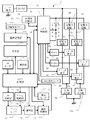
- LEDs 14 a to 14 l Light emitting diodes (hereinafter referred to as “LEDs”) 14 a to 14 l are arranged concentrically around the optical axis of the zoom lens 6 on the front surface of the zoom lens 6, and a photographing auxiliary light device for the digital camera 2 is provided. Forming. With such an arrangement, the LEDs 14a to 14l constitute a so-called ring flash, and illumination with a three-dimensional effect is possible without a bias of shadows. Further, using the fact that the photographing auxiliary light device source of Example 1 is constituted by a plurality of LEDs, as will be described later, the LEDs 14a, 14d, 14g and 14j (hereinafter referred to as “wide-angle LED group”) are referred to as the wide-angle LEDs 14a.
- the camera control unit 16 causes the image processing unit 28 to perform processing such as image compression from the imaging unit 26, and stores it in the image storage unit 34.
- the compressed image is transferred to a storage medium slot into which a memory card or the like is inserted, and stored in the memory card or the like.
- the compressed image stored in the image storage unit 34 or the memory card is decompressed and reproduced on the display unit 30 when the reproduction mode is selected by the operation of the operation unit 18. Electric power necessary for the operation of the digital camera described above is supplied by a power supply circuit (not shown) connected to the rechargeable lithium ion battery 38.
- the color temperature storage unit 68 is composed of a nonvolatile memory, and stores actual measurement values of color temperature information of the wide-angle LED group 14a and the narrow-angle LED group 14b that are important for photography.
- the stored color temperature information is sent from the LED control unit 42 to the camera control 16 when the LEDs 14a to 14l are incorporated in the digital camera, and is reflected in the color correction of the image processing by the image processing unit 28.
- a xenon lamp is generally used as a photographing auxiliary light device for a digital camera, but the xenon gas enclosed in the xenon lamp is white light close to sunlight and has a high color temperature of 6000 K, and the ultraviolet to infrared region (184 nm to 2000 nm). ) Have a wide continuous spectrum.
- the irradiation range is set based on the short-distance virtual subject, but the far field within the angle of view is set. Naturally, the distance virtual subject 70b is also illuminated.
- FIG. 3C shows an illumination situation when all of the wide-angle LED group and the narrow-angle LED group emit light at the telephoto end.
- numbers are not shown for the same individual LEDs as in FIGS. 3A and 3B, but in the state of FIG.
- the wide-angle ELD group also contributes and the absolute illuminance is increasing.
- the illumination efficiency is worse than when only the narrow-angle LED as shown in FIG.
- the reflected light from the object reaches the long distance virtual object 70b within the angle of view, so-called bounce. It is in a shooting state and is not necessarily useless.
- FIG. 4B is a full-lamp mode at all times, and does not change the mixing ratio of the illumination light from the wide-angle LED 14a and the illumination light from the narrow-angle LED group 14b regardless of the focal length.
- This is a mode in which zooming is performed while maintaining the state in which all of the wide-angle LED group 14a and the narrow-angle LED group 14b emit light regardless of zooming as shown in FIG.
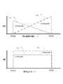
- FIG. 5 is a graph for explaining the overall intensity change of the wide-angle LED group 14a and the narrow-angle LED group 14b according to the distance in Example 1 of FIG. 1, and the horizontal axis indicates the focus distance of the zoom lens 6,
- the vertical axis shows the average light emission intensity of the wide-angle LED group 14a and the narrow-angle LED group 14b.
- the light emission intensity change in this case is also realized by changing the duty of the PWMs 54 and 56 in FIG. 2 in accordance with the focus distance of the zoom lens 6. Specifically, the duty is changed according to distance information to the subject detected during autofocus. Thereby, it is possible to prevent the image from being blown out due to excessive illumination particularly in close-up photography.
- FIG. 8C shows a synchronized continuous shooting mode in which flash emission is performed in synchronization with each exposure time.
- the above-described LED control shown in FIGS. 4 to 8 is all the light emission using the electric charge charged in the EDLC 44 of FIG. 2, but the LED emission is not limited to this route, as described above, as shown in FIG.
- Direct power is supplied from the DC / DC converter 40 to the wide-angle LED group 14a via the constant current circuit 58 and the switch element 60, and to the narrow-angle LED group 14b via the constant current circuit 62 and the switch element 64, respectively. Can be supplied.
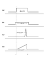
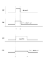
- FIG. 9 is a graph for explaining the proper use of power supply via the EDLC 44 and direct power supply not via the EDLC 44 in the first embodiment of FIG. 1 as described above.
- time is taken on the horizontal axis, and the vertical axis is exposed between t1 and t2 as in FIG. 6A.
- FIG. 9B, FIG. 9E, and FIG. 9H also take time corresponding to the horizontal axis, and the vertical axis represents the wide-angle LED group 14a and the narrow-angle LEDs as in FIG. 6B.
- the average light emission intensity of the group 14b is shown, and the flat light emission is shown.
- 9B, 9E, and 9H are the same, but FIG. 9A, FIG. 9D, and FIG. 9 are used to explain three cases in which power is directly supplied. Each is illustrated in the same manner as 9 (G).
- torch illumination is performed by direct power supply prior to light emission via the EDLC 44 during the exposure time as shown in FIGS. 9A and 9B. It shows how it is. As described above, this torch illumination is useful for determining the composition during autofocus by operating the zoom up / down buttons 8 and 10 and by half-pressing the release button 12, and for providing auxiliary light for autofocus.
- FIG. 9 (F) rapidly contracts the pupil for red-eye reduction prior to light emission via the EDLC 44 during the exposure time as shown in FIGS. 9 (D) and 9 (E).
- a state in which flicker lighting is performed is shown. Such flicker lighting is possible by controlling the switch elements 60 and 64 by the LED control unit 42 of FIG.
- FIG. 9 (I) shows that when the self-timer is used, the LED is blinked prior to light emission via the EDLC 44 during the exposure time as shown in FIGS. 9 (G) and 9 (H). A state in which the self-timer is operating is shown. Such blinking lighting is also possible by controlling the switch elements 60 and 64 by the LED control unit 42 of FIG.
- the various direct lighting shown in FIGS. 9C, 9F, and 9I are not performed separately, but may be combined as appropriate.
- notification display during the timer operation as shown in FIG. 9 (I) may be performed first, and switching to red-eye reduction flicker lighting as shown in FIG. 9 (F) may be performed immediately before exposure.
- torch illumination as shown in FIG. 9C may be performed and switched to red-eye reduction flicker lighting as shown in FIG. 9F immediately before exposure.
- the direct power supply not via the EDLC 44 is not limited to being used in combination with the power supply via the EDLC 44 as shown in FIG. 9, but can be used alone.
- the torch illumination of FIG. 9C can be used alone in moving image shooting that does not require flash emission.
- the blinking lighting for the self-timer display as shown in FIG. 9I can be used alone under bright ambient light that does not require photographing auxiliary light.
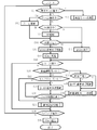
- FIG. 10 is a flowchart of the operation of the camera control unit 16 in the first embodiment of FIGS. 1 and 2.
- step S2 it is checked whether the digital camera 2 is set to the reproduction mode by the GUI of the operation unit 18 and the display unit 30. If the playback mode setting is not detected, the shooting mode is set, and the process proceeds to step S4 to check whether the zoom operation is being performed. If the zoom operation is not being performed, it is checked in step S6 whether the AF operation is being performed. If the AF operation is being performed, the process proceeds to step S8, AF driving is performed, and the process proceeds to step S10.
- step S4 when it is detected in step S4 that the zoom operation is being performed, the process proceeds to step S12, the zoom drive is performed, and the process proceeds to step S10.
- step S10 it is checked whether or not an illuminance deficiency is detected by a photometric sensor or the like. If the illuminance is deficient, the process proceeds to step S13 to instruct the normal lighting drive of all LEDs to start torch illumination. If it is already in torch lighting, continue this. This corresponds to the driving shown in FIG.
- “normal” in lighting in the flow after FIG. 10 means direct driving without passing through the EDLC.
- step S14 charging of EDLC is instructed, and the process proceeds to step S16 in preparation for lighting of the photographing auxiliary light.
- step S6 it is checked whether or not a release operation has been performed by fully pressing the release button.
- step S20 it is checked whether or not it is a moving image shooting mode. If not, the process proceeds to step S22 to check whether or not the self-timer mode is set. If it is the self-timer mode, all the LEDs are normally blinked in step S24, and the process proceeds to step S26. If it is already blinking, this is continued.
- step S26 it is checked whether or not the timer time has elapsed. If it has not yet elapsed, the process returns to step S24, and thereafter, steps S24 and S26 are repeated until the timer time elapses, and the normal blinking drive of the LED is continued. On the other hand, when the elapse of the timer time is detected in step S26, the process proceeds to the imaging recording process in step S28. If it is detected in step S22 that the mode is not the self-timer mode, the process directly proceeds to the imaging recording process in step S28. Details of the imaging recording process will be described later.
- step S30 When the imaging recording process in step S28 is completed, the process proceeds to step S30, and it is checked whether or not an operation for turning off the main switch of the camera has been performed by the operation unit 18. If no camera-off operation is detected, the flow returns to step S2, and thereafter, step S2 to step S30 are repeated unless a playback mode operation is detected in step S2 or a release operation is not detected in step S30. This repetition is sufficiently fast. Therefore, the process based on the operation or the change in the situation is changed in response to the change in the detection result based on Step S4, Step S6, Step S10, Step S16 and Step S22.
- step S2 When a playback mode setting operation using the GUI of the operation unit 18 and the display unit 30 is detected in step S2, the process proceeds to a playback mode process in step S32.
- the shooting mode is selected by the function in the playback mode process, the flow returns to step S4.
- a camera-off operation is detected by a function within the playback mode process, the flow ends.
- step S34 detects whether the illuminance is insufficient. If the illuminance is insufficient, in step S36, normal lighting drive is instructed for all LEDs to start torch illumination, and the process proceeds to the moving image shooting mode in step S38. On the other hand, when lack of illuminance is not detected in step S34, the process directly proceeds to step S38.
- the torch illumination instructed in step S36 corresponds to the driving in FIG.
- step S30 when a camera-off operation by the operation unit 18 is detected in step S30, the process proceeds to step S40.
- step S40 if the charge charged in the EDLC 44 remains unused or partially used, it is regenerated, returned to the lithium ion battery of FIG. 2, and the flow is terminated.
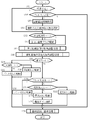
- FIG. 11 is a flowchart showing details of the imaging recording process of FIG.
- step S52 it is checked in step S52 whether the illuminance is insufficient. If the illuminance is not insufficient, the process proceeds to step S54, and it is checked whether or not the fill-in auxiliary light photographing mode is set by the GUI of the operation unit 18 and the display unit 30. If it is the fill-in setting, the process proceeds to step S56, and exposure time data automatically determined by the illuminance sensor 32 or the like in the photographing is acquired.
- step S58 the light emission intensity of the LED is adjusted so that the ratio of the auxiliary light added to the ambient light is maintained, and the process proceeds to step S60.
- the operations in steps S56 and S58 correspond to the functions described in FIG. On the other hand, when it is detected in step S52 that the illuminance is insufficient, the process directly proceeds to step S60.
- step S60 it is checked whether the red-eye reduction mode is set by the GUI of the operation unit 18 and the display unit 30. If applicable, the LED is normally flickered to reduce red-eye in step S62. This corresponds to the function of FIG. Then, when the flicker driving in FIG. 62 ends, the process proceeds to step S64. On the other hand, if it is confirmed in step S that the red-eye reduction mode has not been set, the process directly proceeds to step S64.
- step S64 a focal length-dependent irradiation angle adjustment process is performed. This corresponds to the function described in FIGS. 3A, 3B, and 4A. Further, in step S666, a light emission intensity adjustment process depending on the shooting distance is performed. This corresponds to the function described in FIG.
- step S68 it is checked whether or not the continuous shooting mode is set by the GUI. If the continuous shooting mode setting is not detected, the process proceeds to step S70 to check whether the flat light emission mode setting by the GUI is performed. If not, it is checked in step S72 whether the tail light emission mode is set by the GUI. If this is not the case, it means that the flash emission mode is set, and therefore the process proceeds to step S74, and the flash emission via exposure and EDLC is performed. Then, the process proceeds to step S76, exposure gain adjustment for covering the shortage of light emission is performed, and the process proceeds to step S78. This corresponds to the function described in relation to FIGS. 6 (A) and 6 (C).
- step S70 when it is confirmed in step S70 that the flat light emission mode is set, the process proceeds to step S80, where flat light emission via EDLC and exposure during light emission are performed, and the process proceeds to step S78.
- step S80 flat light emission via EDLC and exposure during light emission are performed
- step S78 This corresponds to the function described in FIGS. 6A and 6B.
- step S82 when it is confirmed in step S72 that the tail light emission mode has been set, the process proceeds to step S82, the tail light emission via exposure and EDLC is performed, and the process proceeds to step S78. This corresponds to the function described in FIG. 6 (A) and FIG. 6 (D). If no fill-in setting is detected in step S54, the shooting is not accompanied by auxiliary light, and the process directly proceeds to step S78.
- step S84 the process proceeds to step S84 to check whether or not the synchronized continuous shooting mode is set. If not in the tuning mode, the process proceeds to step S86, where flat light emission via EDLC during continuous exposure is instructed, and the process proceeds to step S78. This corresponds to the function described in FIGS. 8A and 8B. On the other hand, when it is confirmed in step S84 that the tuning mode is set, the process proceeds to step S88, instructing light emission synchronized with each exposure time during continuous shooting via EDLC, and proceeds to step S78. This corresponds to the function described in FIGS. 8A and 8C.
- step S78 recording of an image detected by the imaging unit 26 during the exposure time and image processing by the image processing unit 28 are performed. As a result, the flow of FIG. 11 ends, and the process proceeds to step S30 of FIG.
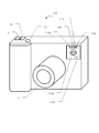
- FIG. 12 is a perspective view showing Example 2 of the digital camera according to the embodiment of the present invention.
- the configuration is the same as that of the first embodiment shown in FIG. 1 except for the arrangement of the photographing auxiliary light device and the like, so that the corresponding parts are denoted by the same reference numerals and description thereof is omitted.
- LEDs 114 a to 114 c are arranged in parallel on the front surface of the camera body 4 to form the photographing auxiliary light device 114.
- the light distribution of the LEDs 114a to 114c may be the same, LEDs having different irradiation angles may be mixed in this arrangement as in the first embodiment of FIG.
- the block diagram of the first embodiment shown in FIG. 2 and the details of the functions shown in FIGS. 4 to 11 can also be adopted in the second embodiment of FIG.
- the photographing auxiliary light device 114 of the second embodiment shown in FIG. 12 is provided with the “LED” character notation 114n indicating that it is a safe LED flash and a safety mark 114p symbolizing a newborn. Yes. As a result, it is possible to widen the shooting scene with the auxiliary shooting light and to prevent troubles with the surroundings.
- the present invention can be applied to a photographing auxiliary light device and a digital camera equipped with the same.
Landscapes
- Engineering & Computer Science (AREA)
- Multimedia (AREA)
- Signal Processing (AREA)
- Physics & Mathematics (AREA)
- General Physics & Mathematics (AREA)
- Studio Devices (AREA)
- Stroboscope Apparatuses (AREA)
- Exposure Control For Cameras (AREA)
- Indication In Cameras, And Counting Of Exposures (AREA)
Priority Applications (1)
| Application Number | Priority Date | Filing Date | Title |
|---|---|---|---|
| US14/365,716 US9451665B2 (en) | 2011-12-20 | 2012-12-10 | Image pickup auxiliary light source device and digital camera provided with same |
Applications Claiming Priority (2)
| Application Number | Priority Date | Filing Date | Title |
|---|---|---|---|
| JP2011278423A JP5948050B2 (ja) | 2011-12-20 | 2011-12-20 | 撮影補助光装置およびこれを備えたデジタルカメラ |
| JP2011-278423 | 2011-12-20 |
Publications (1)
| Publication Number | Publication Date |
|---|---|
| WO2013094457A1 true WO2013094457A1 (ja) | 2013-06-27 |
Family
ID=48668351
Family Applications (1)
| Application Number | Title | Priority Date | Filing Date |
|---|---|---|---|
| PCT/JP2012/081929 Ceased WO2013094457A1 (ja) | 2011-12-20 | 2012-12-10 | 撮影補助光装置およびこれを備えたデジタルカメラ |
Country Status (3)
| Country | Link |
|---|---|
| US (1) | US9451665B2 (enExample) |
| JP (1) | JP5948050B2 (enExample) |
| WO (1) | WO2013094457A1 (enExample) |
Cited By (2)
| Publication number | Priority date | Publication date | Assignee | Title |
|---|---|---|---|---|
| CN106455960A (zh) * | 2014-10-10 | 2017-02-22 | 奥林巴斯株式会社 | 光源装置和光源装置的控制方法 |
| CN110278362A (zh) * | 2019-06-30 | 2019-09-24 | Oppo广东移动通信有限公司 | 电子设备及电子设备的控制方法 |
Families Citing this family (24)
| Publication number | Priority date | Publication date | Assignee | Title |
|---|---|---|---|---|
| WO2014110655A1 (en) * | 2013-01-15 | 2014-07-24 | Avigilon Corporation | Method and apparatus for generating an infrared illumination beam with a variable illumination pattern |
| CN104349072A (zh) * | 2013-08-09 | 2015-02-11 | 联想(北京)有限公司 | 一种控制方法、装置和电子设备 |
| US9237275B2 (en) * | 2013-12-20 | 2016-01-12 | International Business Machines Corporation | Flash photography |
| JP6305091B2 (ja) * | 2014-02-13 | 2018-04-04 | キヤノン株式会社 | 発光装置、その制御方法、および制御プログラム、並びに撮像装置 |
| KR102364084B1 (ko) * | 2014-10-21 | 2022-02-17 | 엘지전자 주식회사 | 이동단말기 및 그 제어방법 |
| US9992396B1 (en) * | 2015-02-02 | 2018-06-05 | Apple Inc. | Focusing lighting module |
| JP6512979B2 (ja) * | 2015-07-23 | 2019-05-15 | キヤノン株式会社 | 撮像装置 |
| CN105187713A (zh) * | 2015-08-03 | 2015-12-23 | 厦门美图之家科技有限公司 | 同时支持拍照与录像的拍摄启动方法、装置及拍摄终端 |
| EP3128750A1 (en) * | 2015-08-04 | 2017-02-08 | Thomson Licensing | Plenoptic camera and method of controlling the same |
| WO2017144102A1 (en) * | 2016-02-25 | 2017-08-31 | Osram Opto Semiconductors Gmbh | Electronic device and method for operating an electronic device |
| DE102016104381A1 (de) | 2016-03-10 | 2017-09-14 | Osram Opto Semiconductors Gmbh | Optoelektronische Leuchtvorrichtung, Verfahren zum Beleuchten einer Szene, Kamera sowie mobiles Endgerät |
| DE102017103660B4 (de) | 2017-02-22 | 2021-11-11 | OSRAM Opto Semiconductors Gesellschaft mit beschränkter Haftung | Verfahren zum betrieb einer lichtquelle für eine kamera, lichtquelle, kamera |
| US10924655B2 (en) * | 2017-11-06 | 2021-02-16 | Canon Kabushiki Kaisha | Image-capturing apparatus and control method thereof |
| JP7080622B2 (ja) * | 2017-11-17 | 2022-06-06 | キヤノン株式会社 | 撮像装置、及びその制御方法、並びにプログラム |
| US10979649B2 (en) * | 2018-01-29 | 2021-04-13 | Don Atkinson | Auxiliary apparatus for a digital imaging device |
| FR3079937B1 (fr) * | 2018-04-06 | 2021-07-09 | Coeur De Jeu | Dispositif de capture d’images multiples presentant chacune une exposition a la lumiere differente. |
| KR102273534B1 (ko) * | 2018-09-14 | 2021-07-07 | 신선영 | 카메라와 동조되는 엘이디 스트로보 장치 |
| UA118644C2 (uk) * | 2018-09-25 | 2019-02-11 | Василь Олександрович Руських | Портативний переносний освітлювальний пристрій для підводної фото- та відеозйомки |
| US11070740B2 (en) | 2019-01-18 | 2021-07-20 | Panasonic I-Pro Sensing Solutions Co., Ltd. | Camera device and IR light irradiating method |
| JP6654749B1 (ja) * | 2019-01-18 | 2020-02-26 | パナソニックi−PROセンシングソリューションズ株式会社 | カメラ装置およびir光照射方法 |
| JP7078560B2 (ja) * | 2019-01-25 | 2022-05-31 | ファナック株式会社 | 精密工作機械 |
| US11019276B1 (en) * | 2019-11-14 | 2021-05-25 | Hand Held Products, Inc. | Apparatuses and methodologies for flicker control |
| US11190705B2 (en) * | 2020-03-16 | 2021-11-30 | Lenovo (Singapore) Pte. Ltd. | Intelligent array of lights for illumination |
| US12483797B2 (en) * | 2022-09-08 | 2025-11-25 | Htc Corporation | Image sensing device and control device of illumination device thereof |
Citations (12)
| Publication number | Priority date | Publication date | Assignee | Title |
|---|---|---|---|---|
| JP2003280071A (ja) * | 2002-03-25 | 2003-10-02 | Fuji Photo Film Co Ltd | フラッシュ付カメラ |
| JP2004045863A (ja) * | 2002-07-12 | 2004-02-12 | Olympus Corp | カメラのためのストロボ装置 |
| JP2005109463A (ja) * | 2003-09-11 | 2005-04-21 | Fujii Dengyosha:Kk | 面状光源と照明装置と照明システム |
| JP2006018181A (ja) * | 2004-07-05 | 2006-01-19 | Sony Ericsson Mobilecommunications Japan Inc | 携帯型電子装置撮影システム、撮影補助光生成装置、携帯型電子装置、電力供給装置 |
| WO2006088039A1 (ja) * | 2005-02-16 | 2006-08-24 | Nikon Corporation | 撮影用照明装置およびカメラ |
| JP2007047192A (ja) * | 2005-07-11 | 2007-02-22 | Sigma Corp | マクロ付き撮影レンズの自動照明装置 |
| JP2008151975A (ja) * | 2006-12-15 | 2008-07-03 | Casio Comput Co Ltd | 撮影装置及びそのプログラム |
| JP2008235423A (ja) * | 2007-03-19 | 2008-10-02 | Fujifilm Corp | 照明装置及びその発光方法、並びに撮影装置 |
| JP2010102208A (ja) * | 2008-10-27 | 2010-05-06 | Citizen Electronics Co Ltd | 撮影用補助光源装置 |
| JP2010175596A (ja) * | 2009-01-27 | 2010-08-12 | Sony Ericsson Mobilecommunications Japan Inc | 携帯機器および発光素子駆動回路 |
| JP2010220110A (ja) * | 2009-03-18 | 2010-09-30 | Ricoh Co Ltd | 撮像装置およびカメラ |
| JP2011158696A (ja) * | 2010-02-01 | 2011-08-18 | Panasonic Corp | 撮像装置及び携帯機器 |
Family Cites Families (12)
| Publication number | Priority date | Publication date | Assignee | Title |
|---|---|---|---|---|
| US5285232A (en) * | 1989-12-21 | 1994-02-08 | Canon Kabushiki Kaisha | Red-eye phenomenon preventing device |
| AUPQ056099A0 (en) * | 1999-05-25 | 1999-06-17 | Silverbrook Research Pty Ltd | A method and apparatus (pprint01) |
| JP4282910B2 (ja) | 2001-03-05 | 2009-06-24 | 株式会社リコー | 撮影用照明装置 |
| US6892029B2 (en) | 2002-06-06 | 2005-05-10 | Olympus Optical Co., Ltd. | Strobe light emitting apparatus and camera |
| JP3833646B2 (ja) * | 2003-09-25 | 2006-10-18 | ローム株式会社 | 画像撮影装置 |
| US20060093344A1 (en) * | 2004-11-01 | 2006-05-04 | Eastman Kodak Company | Ring flash for camera |
| JP4887795B2 (ja) * | 2006-01-19 | 2012-02-29 | カシオ計算機株式会社 | 閃光装置付撮像装置、及び撮像方法 |
| JP5007523B2 (ja) * | 2006-05-02 | 2012-08-22 | カシオ計算機株式会社 | 撮像装置及びそのプログラム |
| JP2010004691A (ja) | 2008-06-23 | 2010-01-07 | Mitsumi Electric Co Ltd | フラッシュ用電源装置 |
| JP2010122336A (ja) | 2008-11-18 | 2010-06-03 | Panasonic Corp | ストロボ回路 |
| US8922708B2 (en) * | 2009-05-07 | 2014-12-30 | Nokia Corporation | Apparatus methods and computer readable storage mediums for exposure control |
| US20130002199A1 (en) * | 2011-06-29 | 2013-01-03 | Ran Hu | Charging of Li-ion Batteries |
-
2011
- 2011-12-20 JP JP2011278423A patent/JP5948050B2/ja not_active Expired - Fee Related
-
2012
- 2012-12-10 WO PCT/JP2012/081929 patent/WO2013094457A1/ja not_active Ceased
- 2012-12-10 US US14/365,716 patent/US9451665B2/en not_active Expired - Fee Related
Patent Citations (12)
| Publication number | Priority date | Publication date | Assignee | Title |
|---|---|---|---|---|
| JP2003280071A (ja) * | 2002-03-25 | 2003-10-02 | Fuji Photo Film Co Ltd | フラッシュ付カメラ |
| JP2004045863A (ja) * | 2002-07-12 | 2004-02-12 | Olympus Corp | カメラのためのストロボ装置 |
| JP2005109463A (ja) * | 2003-09-11 | 2005-04-21 | Fujii Dengyosha:Kk | 面状光源と照明装置と照明システム |
| JP2006018181A (ja) * | 2004-07-05 | 2006-01-19 | Sony Ericsson Mobilecommunications Japan Inc | 携帯型電子装置撮影システム、撮影補助光生成装置、携帯型電子装置、電力供給装置 |
| WO2006088039A1 (ja) * | 2005-02-16 | 2006-08-24 | Nikon Corporation | 撮影用照明装置およびカメラ |
| JP2007047192A (ja) * | 2005-07-11 | 2007-02-22 | Sigma Corp | マクロ付き撮影レンズの自動照明装置 |
| JP2008151975A (ja) * | 2006-12-15 | 2008-07-03 | Casio Comput Co Ltd | 撮影装置及びそのプログラム |
| JP2008235423A (ja) * | 2007-03-19 | 2008-10-02 | Fujifilm Corp | 照明装置及びその発光方法、並びに撮影装置 |
| JP2010102208A (ja) * | 2008-10-27 | 2010-05-06 | Citizen Electronics Co Ltd | 撮影用補助光源装置 |
| JP2010175596A (ja) * | 2009-01-27 | 2010-08-12 | Sony Ericsson Mobilecommunications Japan Inc | 携帯機器および発光素子駆動回路 |
| JP2010220110A (ja) * | 2009-03-18 | 2010-09-30 | Ricoh Co Ltd | 撮像装置およびカメラ |
| JP2011158696A (ja) * | 2010-02-01 | 2011-08-18 | Panasonic Corp | 撮像装置及び携帯機器 |
Cited By (4)
| Publication number | Priority date | Publication date | Assignee | Title |
|---|---|---|---|---|
| CN106455960A (zh) * | 2014-10-10 | 2017-02-22 | 奥林巴斯株式会社 | 光源装置和光源装置的控制方法 |
| EP3205258A4 (en) * | 2014-10-10 | 2018-08-01 | Olympus Corporation | Light source device and method for controlling light source device |
| US10219342B2 (en) | 2014-10-10 | 2019-02-26 | Olympus Corporation | Light source device and control method of light source device |
| CN110278362A (zh) * | 2019-06-30 | 2019-09-24 | Oppo广东移动通信有限公司 | 电子设备及电子设备的控制方法 |
Also Published As
| Publication number | Publication date |
|---|---|
| JP5948050B2 (ja) | 2016-07-06 |
| US9451665B2 (en) | 2016-09-20 |
| US20140340572A1 (en) | 2014-11-20 |
| JP2013130631A (ja) | 2013-07-04 |
Similar Documents
| Publication | Publication Date | Title |
|---|---|---|
| JP5948050B2 (ja) | 撮影補助光装置およびこれを備えたデジタルカメラ | |
| JP5474653B2 (ja) | 撮像装置及び撮像方法 | |
| US9298063B2 (en) | Lighting device and photographing system including the same | |
| JP5858744B2 (ja) | 撮像装置及びカメラシステム | |
| US7606480B2 (en) | Photographic illuminating device and camera | |
| US7660520B2 (en) | Camera system with current and discharge controlled illumination | |
| JP6305091B2 (ja) | 発光装置、その制御方法、および制御プログラム、並びに撮像装置 | |
| CN103986866A (zh) | 成像装置、成像方法及发光装置 | |
| JP2017009932A (ja) | 撮像システム、照明装置及び焦点検出方法 | |
| WO2006088039A1 (ja) | 撮影用照明装置およびカメラ | |
| JP5063184B2 (ja) | 撮像装置、発光装置及び撮像装置の制御方法 | |
| KR101342970B1 (ko) | 촬상장치, 카메라 시스템 및 조명장치 | |
| JP2006010746A (ja) | 撮影用照明装置およびカメラ | |
| JP2013160842A (ja) | デジタルカメラ | |
| JP2005352252A (ja) | カメラ | |
| JP2006138900A (ja) | 撮影用照明装置およびカメラ | |
| JP2017103966A (ja) | 電子機器 | |
| JP2007047544A (ja) | ストロボ装置 | |
| JP2006126814A (ja) | 撮像装置、その制御方法及び制御プログラム | |
| JP2015191000A (ja) | 撮影装置、フラッシュ装置及びフラッシュ撮影システム | |
| JP7374778B2 (ja) | 撮像装置及びその制御方法 | |
| JP5332536B2 (ja) | 撮像装置 | |
| JP2024013937A (ja) | 発光制御装置、撮像システム、発光装置の制御方法およびプログラム | |
| JP2006135894A (ja) | プロジェクタ内蔵デジタルカメラ | |
| JP2010066574A (ja) | 電子カメラ |
Legal Events
| Date | Code | Title | Description |
|---|---|---|---|
| 121 | Ep: the epo has been informed by wipo that ep was designated in this application |
Ref document number: 12860466 Country of ref document: EP Kind code of ref document: A1 |
|
| WWE | Wipo information: entry into national phase |
Ref document number: 14365716 Country of ref document: US |
|
| NENP | Non-entry into the national phase |
Ref country code: DE |
|
| 122 | Ep: pct application non-entry in european phase |
Ref document number: 12860466 Country of ref document: EP Kind code of ref document: A1 |