WO2013084829A1 - 端子付電線及びその製造方法 - Google Patents
端子付電線及びその製造方法 Download PDFInfo
- Publication number
- WO2013084829A1 WO2013084829A1 PCT/JP2012/081172 JP2012081172W WO2013084829A1 WO 2013084829 A1 WO2013084829 A1 WO 2013084829A1 JP 2012081172 W JP2012081172 W JP 2012081172W WO 2013084829 A1 WO2013084829 A1 WO 2013084829A1
- Authority
- WO
- WIPO (PCT)
- Prior art keywords
- terminal
- wire
- insulated wire
- adhesive layer
- electric wire
- Prior art date
Links
Images

Classifications
-
- H—ELECTRICITY
- H01—ELECTRIC ELEMENTS
- H01B—CABLES; CONDUCTORS; INSULATORS; SELECTION OF MATERIALS FOR THEIR CONDUCTIVE, INSULATING OR DIELECTRIC PROPERTIES
- H01B7/00—Insulated conductors or cables characterised by their form
- H01B7/17—Protection against damage caused by external factors, e.g. sheaths or armouring
- H01B7/28—Protection against damage caused by moisture, corrosion, chemical attack or weather
- H01B7/282—Preventing penetration of fluid, e.g. water or humidity, into conductor or cable
- H01B7/2825—Preventing penetration of fluid, e.g. water or humidity, into conductor or cable using a water impermeable sheath
-
- B—PERFORMING OPERATIONS; TRANSPORTING
- B29—WORKING OF PLASTICS; WORKING OF SUBSTANCES IN A PLASTIC STATE IN GENERAL
- B29C—SHAPING OR JOINING OF PLASTICS; SHAPING OF MATERIAL IN A PLASTIC STATE, NOT OTHERWISE PROVIDED FOR; AFTER-TREATMENT OF THE SHAPED PRODUCTS, e.g. REPAIRING
- B29C45/00—Injection moulding, i.e. forcing the required volume of moulding material through a nozzle into a closed mould; Apparatus therefor
- B29C45/14—Injection moulding, i.e. forcing the required volume of moulding material through a nozzle into a closed mould; Apparatus therefor incorporating preformed parts or layers, e.g. injection moulding around inserts or for coating articles
- B29C45/14467—Joining articles or parts of a single article
-
- B—PERFORMING OPERATIONS; TRANSPORTING
- B29—WORKING OF PLASTICS; WORKING OF SUBSTANCES IN A PLASTIC STATE IN GENERAL
- B29C—SHAPING OR JOINING OF PLASTICS; SHAPING OF MATERIAL IN A PLASTIC STATE, NOT OTHERWISE PROVIDED FOR; AFTER-TREATMENT OF THE SHAPED PRODUCTS, e.g. REPAIRING
- B29C45/00—Injection moulding, i.e. forcing the required volume of moulding material through a nozzle into a closed mould; Apparatus therefor
- B29C45/14—Injection moulding, i.e. forcing the required volume of moulding material through a nozzle into a closed mould; Apparatus therefor incorporating preformed parts or layers, e.g. injection moulding around inserts or for coating articles
- B29C45/14639—Injection moulding, i.e. forcing the required volume of moulding material through a nozzle into a closed mould; Apparatus therefor incorporating preformed parts or layers, e.g. injection moulding around inserts or for coating articles for obtaining an insulating effect, e.g. for electrical components
-
- H—ELECTRICITY
- H01—ELECTRIC ELEMENTS
- H01B—CABLES; CONDUCTORS; INSULATORS; SELECTION OF MATERIALS FOR THEIR CONDUCTIVE, INSULATING OR DIELECTRIC PROPERTIES
- H01B13/00—Apparatus or processes specially adapted for manufacturing conductors or cables
- H01B13/06—Insulating conductors or cables
- H01B13/08—Insulating conductors or cables by winding
-
- H—ELECTRICITY
- H01—ELECTRIC ELEMENTS
- H01B—CABLES; CONDUCTORS; INSULATORS; SELECTION OF MATERIALS FOR THEIR CONDUCTIVE, INSULATING OR DIELECTRIC PROPERTIES
- H01B3/00—Insulators or insulating bodies characterised by the insulating materials; Selection of materials for their insulating or dielectric properties
- H01B3/18—Insulators or insulating bodies characterised by the insulating materials; Selection of materials for their insulating or dielectric properties mainly consisting of organic substances
- H01B3/30—Insulators or insulating bodies characterised by the insulating materials; Selection of materials for their insulating or dielectric properties mainly consisting of organic substances plastics; resins; waxes
- H01B3/44—Insulators or insulating bodies characterised by the insulating materials; Selection of materials for their insulating or dielectric properties mainly consisting of organic substances plastics; resins; waxes vinyl resins; acrylic resins
- H01B3/441—Insulators or insulating bodies characterised by the insulating materials; Selection of materials for their insulating or dielectric properties mainly consisting of organic substances plastics; resins; waxes vinyl resins; acrylic resins from alkenes
-
- H—ELECTRICITY
- H01—ELECTRIC ELEMENTS
- H01B—CABLES; CONDUCTORS; INSULATORS; SELECTION OF MATERIALS FOR THEIR CONDUCTIVE, INSULATING OR DIELECTRIC PROPERTIES
- H01B3/00—Insulators or insulating bodies characterised by the insulating materials; Selection of materials for their insulating or dielectric properties
- H01B3/18—Insulators or insulating bodies characterised by the insulating materials; Selection of materials for their insulating or dielectric properties mainly consisting of organic substances
- H01B3/30—Insulators or insulating bodies characterised by the insulating materials; Selection of materials for their insulating or dielectric properties mainly consisting of organic substances plastics; resins; waxes
- H01B3/44—Insulators or insulating bodies characterised by the insulating materials; Selection of materials for their insulating or dielectric properties mainly consisting of organic substances plastics; resins; waxes vinyl resins; acrylic resins
- H01B3/447—Insulators or insulating bodies characterised by the insulating materials; Selection of materials for their insulating or dielectric properties mainly consisting of organic substances plastics; resins; waxes vinyl resins; acrylic resins from acrylic compounds
-
- H—ELECTRICITY
- H01—ELECTRIC ELEMENTS
- H01R—ELECTRICALLY-CONDUCTIVE CONNECTIONS; STRUCTURAL ASSOCIATIONS OF A PLURALITY OF MUTUALLY-INSULATED ELECTRICAL CONNECTING ELEMENTS; COUPLING DEVICES; CURRENT COLLECTORS
- H01R4/00—Electrically-conductive connections between two or more conductive members in direct contact, i.e. touching one another; Means for effecting or maintaining such contact; Electrically-conductive connections having two or more spaced connecting locations for conductors and using contact members penetrating insulation
- H01R4/70—Insulation of connections
-
- H—ELECTRICITY
- H01—ELECTRIC ELEMENTS
- H01R—ELECTRICALLY-CONDUCTIVE CONNECTIONS; STRUCTURAL ASSOCIATIONS OF A PLURALITY OF MUTUALLY-INSULATED ELECTRICAL CONNECTING ELEMENTS; COUPLING DEVICES; CURRENT COLLECTORS
- H01R43/00—Apparatus or processes specially adapted for manufacturing, assembling, maintaining, or repairing of line connectors or current collectors or for joining electric conductors
- H01R43/005—Apparatus or processes specially adapted for manufacturing, assembling, maintaining, or repairing of line connectors or current collectors or for joining electric conductors for making dustproof, splashproof, drip-proof, waterproof, or flameproof connection, coupling, or casing
-
- B—PERFORMING OPERATIONS; TRANSPORTING
- B29—WORKING OF PLASTICS; WORKING OF SUBSTANCES IN A PLASTIC STATE IN GENERAL
- B29L—INDEXING SCHEME ASSOCIATED WITH SUBCLASS B29C, RELATING TO PARTICULAR ARTICLES
- B29L2031/00—Other particular articles
- B29L2031/34—Electrical apparatus, e.g. sparking plugs or parts thereof
- B29L2031/3462—Cables
-
- H—ELECTRICITY
- H01—ELECTRIC ELEMENTS
- H01B—CABLES; CONDUCTORS; INSULATORS; SELECTION OF MATERIALS FOR THEIR CONDUCTIVE, INSULATING OR DIELECTRIC PROPERTIES
- H01B3/00—Insulators or insulating bodies characterised by the insulating materials; Selection of materials for their insulating or dielectric properties
- H01B3/18—Insulators or insulating bodies characterised by the insulating materials; Selection of materials for their insulating or dielectric properties mainly consisting of organic substances
- H01B3/30—Insulators or insulating bodies characterised by the insulating materials; Selection of materials for their insulating or dielectric properties mainly consisting of organic substances plastics; resins; waxes
- H01B3/308—Wires with resins
-
- H—ELECTRICITY
- H01—ELECTRIC ELEMENTS
- H01R—ELECTRICALLY-CONDUCTIVE CONNECTIONS; STRUCTURAL ASSOCIATIONS OF A PLURALITY OF MUTUALLY-INSULATED ELECTRICAL CONNECTING ELEMENTS; COUPLING DEVICES; CURRENT COLLECTORS
- H01R11/00—Individual connecting elements providing two or more spaced connecting locations for conductive members which are, or may be, thereby interconnected, e.g. end pieces for wires or cables supported by the wire or cable and having means for facilitating electrical connection to some other wire, terminal, or conductive member, blocks of binding posts
- H01R11/11—End pieces or tapping pieces for wires, supported by the wire and for facilitating electrical connection to some other wire, terminal or conductive member
- H01R11/12—End pieces terminating in an eye, hook, or fork
Definitions
- the present invention relates to an insulated wire and an electric wire with a terminal including a metal terminal provided at an end thereof, and a method for manufacturing the same.
- the electric wire with a terminal having a waterproof function includes a waterproof resin portion that covers the waterproof region at the end.
- the electric wire with terminal provided with the waterproof resin portion is referred to as an electric wire with waterproof terminal.
- the waterproof resin portion is made of a synthetic resin material, and covers the protection region by insert molding with the protection region including the region from the insulating coating portion at the end of the insulated wire to the connection portion with the core wire in the metal terminal as the insert portion. It is a formed part.
- an adhesive is applied to the entire surface of the insulating coating at the end of the insulated wire.
- This adhesive serves as an adhesive layer that bonds the insulating coating and the waterproof resin portion while closing the gap between the insulating coating and the waterproof resin portion.
- This adhesive layer also functions as a water stop portion that prevents water from entering.
- the adhesive layer has elasticity that can cope with the difference in thermal expansion between the insulating coating and the waterproof resin portion.
- a water-based and elastic silicone-based resin or rubber-based resin adhesive is used as a material for an adhesive functioning as a water-stopping agent.
- the insulated wire has an insulating coating of a polyolefin resin, which is an olefin resin
- a polyolefin resin which is an olefin resin
- an adhesive layer of a silicon resin or a rubber resin is employed, the adhesion between the insulating coating and the waterproof resin portion (waterproofing) ) Is insufficient. Therefore, it is easy for water to enter the connecting portion between the core wire and the metal terminal, and this water immersion causes corrosion and contact failure at the connecting portion between the core wire and the metal terminal.
- Patent Document 1 in the manufacturing process of a waterproof terminal-attached electric wire, corona discharge treatment or plasma discharge treatment is applied to the insulation coating of the insulated wire, thereby improving the adhesion between the olefin-based resin insulation coating and the adhesive. It has been shown.
- the present invention provides a terminal-attached electric wire having a waterproof resin portion that covers a connection portion between an insulated wire and a metal terminal, without requiring an increase in manufacturing man-hours and equipment, and between the insulation coating of the polyolefin resin and the waterproof resin portion.
- the purpose is to increase the water-stopping property of this part.
- the electric wire with terminal according to the present invention includes the following components.
- the first component is an insulated wire having a conductive core wire and a polyolefin resin insulation coating covering the periphery of the core wire.
- the second component is a metal terminal electrically connected to the core wire at the end of the insulated wire.
- the third component is composed of a blend of a copolymer of ethylene and glycidyl methacrylate and a phenolic curing agent, and is formed on the entire surface of the insulating coating at the end of the insulated wire. Adhesive layer.
- the fourth component is made of aromatic nylon, and inserts a protective region including a region from at least a portion where the adhesive layer is formed in the insulated wire to a connection portion with the core wire in the metal terminal.
- the waterproof resin portion is formed so as to cover the protection region by insert molding.
- the adhesive layer is preferably made of a material that causes an elongation of 104.7% or more in an environment of ⁇ 40 ° C. according to a test according to JIS K6251.
- the adhesive strength of the insulating coating and the adhesive layer is 183 kPa or more under an environment of 150 ° C. according to a test according to JIS K6850.
- the present invention may be understood as an invention of a method for manufacturing a terminal-attached electric wire according to the present invention. That is, the manufacturing method suitable for manufacturing the electric wire with terminal according to the present invention includes the steps shown below.
- an adhesive sheet which is a sheet-like adhesive composed of a blend of a copolymer of ethylene and glycidyl methacrylate and a phenolic curing agent, is used in the protection region at the end of the insulated wire. It is a sheet winding process in which the insulating coating is wound over the entire circumference.
- the second step is an adhesion step in which the adhesive sheet wound around the end portion of the insulated wire is adhered to the insulating coating of the insulated wire by heating.
- the third step is insert molding in which a resin material made of aromatic nylon is molded into the waterproof resin portion having a shape covering the protective region by insert molding using the protective region in the insulated wire as an insert portion. It is a process.
- the insulation coating of the polyolefin resin and the waterproof resin portion are not required without increasing the number of manufacturing steps and equipment. It is possible to increase the water stoppage of the portion between.
- the lead time for manufacturing the electric wire with terminal according to the present invention is significantly reduced.
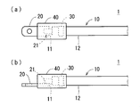
- the terminal-attached electric wire 1 includes an insulated electric wire 10, a metal terminal 20, an adhesive layer 30, and a waterproof resin portion 40.
- the insulated wire 10 includes a conductive core wire 11 and an insulating coating 12 made of a polyolefin resin that covers the periphery of the core wire 11.
- the end of the core wire 11 is formed to extend from the end of the insulating coating 12.
- the core wire 11 is made of a metal material such as copper, a copper alloy, or an aluminum alloy, for example.
- the insulating coating 12 is made of, for example, a polyolefin resin such as crosslinked polyethylene or crosslinked polypropylene.
- the metal terminal 20 is a terminal electrically connected to the core wire 11 at the end of the insulated wire 10.
- the metal terminal 20 is a metal fitting made of a metal material such as copper or a copper alloy.
- the metal terminal 20 is a portion connected to a connection partner such as a bus bar, a terminal portion of an electrical equipment, or a terminal of another terminal-attached electric wire.
- the metal terminal 20 is a flat terminal having a through hole through which a screw is passed.
- the metal terminal 20 has other shapes such as a plate shape or a rod shape without a through hole.
- the metal terminal 20 is fixed to the core wire 11 at the end of the insulated wire 10 by ultrasonic welding or the like.
- the metal terminal 20 is a crimp terminal in which a crimped portion to be crimped to each of the core wire 11 and the insulation coating 12 portion of the insulated wire 10 is formed, the metal terminal 20 is crimped to the end portion of the insulated wire 10. To be fixed.
- the adhesive layer 30 is an adhesive layer formed on the entire surface of the insulating coating 12 at the end of the insulated wire 10.
- the adhesive layer 30 adheres the outer surface of the insulating coating 12 and the inner surface of the waterproof resin portion 40 and closes the gap between them.
- the waterproof resin portion 40 is a resin member that is formed so as to cover the protection region by insert molding using the predetermined protection region at the end of the terminal-attached electric wire 1 as an insert portion.
- the protection region is a region including at least a region from the portion of the insulated wire 10 where the adhesive layer 30 is formed to the connection portion 21 of the metal terminal 20 with the core wire 11.
- the characteristic of the electric wire 1 with a terminal lies in a combination of materials of the adhesive layer 30 and the waterproof resin portion 40 with respect to the insulating coating 12 of polyolefin resin. That is, in the electric wire with terminal 1, the adhesive layer 30 is an adhesive layer made of a blend of a copolymer of ethylene and glycidyl methacrylate and a phenolic curing agent. Further, the waterproof resin portion 40 is a resin member made of aromatic nylon. In the following description, a copolymer of ethylene and glycidyl methacrylate is referred to as an ET-GMA copolymer.
- the phenolic curing agent serves as a crosslinking agent.
- the phenolic curing agent may be either a novolac type phenol resin or a resol type phenol resin. Note that the novolac type phenolic resin is heated together with the curing agent, and the reaction proceeds, and three-dimensional crosslinking is performed and cured. On the other hand, a resol type phenol resin reacts by itself being heated, and is cured by three-dimensional crosslinking.
- glycidyl methacrylate contained in the ET-GMA copolymer is a bifunctional monomer containing an acrylic group and an epoxy group.
- FIG. 2 is a schematic diagram showing a manufacturing procedure of the terminal-attached electric wire 1.
- a terminal connection process is a process of attaching the metal terminal 20 to the edge part of the insulated wire 10 by welding or caulking. As a result, as shown in FIG. 2A, the core wire 11 and the metal terminal 20 of the insulated wire 10 are integrally coupled and electrically connected.
- the metal terminal 20 before being connected to the insulated wire 10 is drawn by a virtual line (two-dot chain line).
- the sheet winding step is a step of winding the adhesive sheet 30 ⁇ / b> S, which is a sheet-like adhesive, around the entire periphery of the insulating coating 12 at the end of the insulated wire 10.
- the adhesive sheet 30S is a sheet-like adhesive made of a blend of an ET-GMA copolymer and a phenolic curing agent.
- the adhesive sheet 30S is formed with a thickness of about several tens of micrometers to several hundreds of micrometers, for example.
- the terminal portion of the adhesive sheet 30S wound around the insulating coating 12 is temporarily fixed to the other part of the adhesive sheet 30S by being heated by a heated metal member or the like.
- the adhesive sheet 30 ⁇ / b> S is held in an annular shape while being wound around the insulating coating 12.
- the adhesive sheet 30S that is the base of the adhesive layer 30 is made of a thermoplastic synthetic resin, and is a so-called hot melt type adhesive.
- the bonding step is a step of bonding the adhesive sheet 30 ⁇ / b> S wound around the end portion of the insulated wire 10 to the insulating coating 12 of the insulated wire 10 by heating with the heater 51.
- an adhesive layer 30 made of a blend of the ET-GMA copolymer and the phenolic curing agent is formed on the surface of the insulating coating 12 at the end of the insulated wire 10.
- the adoption of the adhesive sheet 30S eliminates the need for an application step of applying an adhesive diluted with a volatile solvent to the surface of the insulating coating 12, and a drying step of volatilizing the solvent.
- the drying process takes a long time to completely volatilize the solvent. Accordingly, the lead time for manufacturing the terminal-attached electric wire 1 is greatly shortened by eliminating the drying process.
- a molten resin material 40P made of aromatic nylon is formed into a waterproof resin portion 40 having a shape covering the protection region of the terminal-attached electric wire 1 by insert molding using the protection region in the insulated wire 10 as an insert portion. It is a process to do.
- the protection region of the terminal-attached electric wire 1 is arranged at a predetermined position inside the mold 52 for molding the waterproof resin portion 40.
- a molten resin material 40P made of aromatic nylon is injected from the resin supply device 53 into the mold 52.
- the waterproof resin part 40 of aromatic nylon is shape
- FIG. 2D is a cross-sectional view of the mold 52.
- the mold 52 shown in FIG. 1 is a cross-sectional view of the mold 52.
- the adhesive layer 30 once solidified before the insert molding is temporarily softened by the heat of the molten resin in the insert molding and welded to the waterproof resin portion 40 that is a molded product. Thereby, the waterproof resin part 40 adhere
- the adhesive layer 30 is not peeled off from the insulating coating 12 by the pressure received from the injected molten resin during the insert molding. That is, the adhesive strength of the insulating coating 12 and the adhesive layer 30 needs to exceed the maximum shear stress received from the molten resin during insert molding.
- the adhesive strength of the insulating coating 12 and the adhesive layer 30 is desirably 183 kPa or more under an environment (atmosphere temperature) of 150 ° C. according to a test according to JIS K6850.
- both the ethylene constituting the adhesive layer 30 and the polyolefin resin constituting the insulating coating 12 are olefin resins, they are easily bonded to each other at the molecular level and are firmly bonded.
- the glycidyl methacrylate constituting the adhesive layer 30 has a polar group (epoxy group), and the aromatic nylon that is the material of the waterproof resin portion 40 also has a polar group (amide group). Therefore, the adhesive layer 30 and the waterproof resin portion 40 are firmly bonded by the attractive force of each polar group.
- the insulating coating 12 made of polyolefin resin and the waterproof resin portion 40 made of aromatic nylon are strongly bonded by the adhesive layer 30 made of a blend of an ET-GMA copolymer and a phenolic curing agent. Glued to.
- the adhesive layer 30 containing the ET-GMA copolymer has sufficient stretchability to cope with the difference in thermal expansion between the insulating coating 12 and the waterproof resin portion 40, and is excellent in water resistance. Therefore, by adopting the terminal-attached electric wire 1, it is possible to increase the water stoppage of the portion between the insulating coating 12 and the waterproof resin portion 40. And when the electric wire 1 with a terminal is employ
- the adhesive layer 30 containing the ET-GMA copolymer and the waterproof resin portion 40 made of aromatic nylon are also excellent in oil resistance. Therefore, the electric wire with terminal 1 is also suitable for use in a place where oil such as engine oil or brake oil is assumed to be attached in an automobile. Moreover, the adhesive layer 30 containing a phenol type curing agent is also excellent in heat resistance. Therefore, the terminal-attached electric wire 1 is also suitable for use in a place where the temperature is high in an automobile.
- a resin comprising a blend of an ET-GMA copolymer and a phenolic curing agent can be formed into a sheet shape. Therefore, in the process of forming the adhesive layer 30, a process of winding the adhesive sheet 30S around the insulated wire 10 and heating the adhesive sheet 30S can be employed. In this case, an application step for applying the adhesive diluted with a volatile solvent to the surface of the insulating coating 12 and a drying step for volatilizing the solvent are not necessary. As a result, the lead time for manufacturing the electric wire with terminal 1 is greatly shortened.
- the thickness of the insulation coating 12 in the insulated wire 10 is often 0.7 mm or less.
- the thickness of the waterproof resin part 40 is preferably about 1.0 mm.
- the adhesive layer 30 has a stretchability that fills the difference in thermal expansion between the insulating coating 12 and the waterproof resin portion 40 under the above-described conditions.
- the adhesive layer 30 has an elongation of 104.7% or more under an environment (atmosphere temperature) of ⁇ 40 ° C., which is the most severe environmental temperature in terms of stretchability, according to a test in accordance with JIS K6251. It is desirable to be made of a material that generates
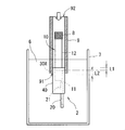
- FIG. 3 is a schematic diagram showing a test method for evaluating the waterproof performance of the terminal-attached electric wire 1.
- the evaluation test of the waterproof performance of the terminal-attached electric wire 1 is a test comparing the electric wire with terminal 1 and two types of electric wires with terminal that are different from the electric wire with terminal 1 only in the material of the adhesive layer.
- the three types of terminal-attached electric wires to be evaluated are collectively referred to as an evaluation sample 2.
- 3 represents an adhesive layer of the evaluation sample 2.
- FIG. 3 the same components as those shown in FIGS. 1 and 2 are denoted by the same reference numerals.
- the end of the insulated wire 10 opposite to the side connected to the metal terminal 20 is aired to the inside of the insulating coating 12 by a closing material 8 such as a heat-shrinkable tube. It is sealed so as not to enter.
- the dimension L1 from the end of the waterproof resin portion 40 to the adhesive layer 30X is 2 mm. That is, the adhesive layer 30 ⁇ / b> X is formed at a position recessed 2 mm from the end of the waterproof resin portion 40. Furthermore, in the evaluation sample 2, the width L2 of the adhesive layer 30X is 10 mm. The thickness of the adhesive layer 30X is 10 ⁇ m or more.
- the diameter of the core wire 11 is 2.4 mm
- the thickness of the insulating coating 12 is 0.7 mm
- the thickness of the portion covering the insulating coating 12 in the waterproof resin portion 40 is 2.02 mm.
- the part from the part of the waterproof resin part 40 to the end part of the insulated wire 10 on the side sealed with the closing material 8 in the evaluation sample 2 is inserted into the inside of the cylindrical member 9. Retained. Furthermore, one opening 91 of the cylindrical member 9 is sealed by the waterproof resin portion 40.
- the region from the metal terminal 20 at the tip to a part of the insulated wire 10 surrounded by the tubular member 9 in the evaluation sample 2 is immersed in the water 6 stored in the water tank 7. Further, in the evaluation test, compressed air having a pressure of a maximum of 100 kPa is supplied from the other opening 92 of the cylindrical member 9.
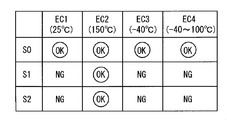
- the first test condition EC1 is a condition in which the environmental temperature is maintained at room temperature (about 25 ° C.).
- the second test condition EC2 is a condition in which the environmental temperature is maintained at 150 ° C.
- the third test condition EC3 is a condition in which the environmental temperature is maintained at ⁇ 40 ° C.
- the fourth test condition EC4 is a condition in which the environmental temperature changes between ⁇ 40 ° C. and 100 ° C. in 5 minutes and is maintained at ⁇ 40 ° C. or 100 ° C. for 30 minutes.
- FIG. 4 is a diagram showing the evaluation results of the waterproof performance of the terminal-attached electric wire 1.
- codes S0, S1, and S2 are identification codes of three types of evaluation samples 2.
- the 1st evaluation sample S0 is the electric wire 1 with a terminal. That is, the adhesive layer 30X of the first evaluation sample S0 is an adhesive layer made of a blend of an ET-GMA copolymer and a phenolic curing agent. On the other hand, the adhesive layer 30X of the second evaluation sample S1 is a layer of silicon adhesive. The adhesive layer 30X of the third evaluation sample S2 is a butyl rubber adhesive layer.
Abstract
Description
まず、図1を参照しつつ、本発明の実施形態に係る端子付電線1の構成について説明する。図1に示されるように、端子付電線1は、絶縁電線10と金属端子20と接着層30と防水樹脂部40とを備える。
次に、図2を参照しつつ、端子付電線1の製造手順の概略について説明する。なお、図2は、端子付電線1の製造手順を示す模式図である。
接着層30を構成するエチレン及び絶縁被覆12を構成するポリオレフィン系樹脂は、いずれもオレフィン系樹脂であるため、相互に分子レベルで結合しやすく、強固に接合する。
以下、図3及び図4を参照しつつ、端子付電線1の防水性能の評価方法及び評価結果について説明する。図3は、端子付電線1の防水性能の評価のための試験方法を示す模式図である。
2 評価サンプル
EC1,EC2,EC3,EC4 試験条件(温度条件)の識別符号
S0,S1,S2 評価サンプルの識別符号
6 水
7 水槽
8 閉塞材
9 筒部材
10 絶縁電線
11 芯線
12 絶縁被覆
20 金属端子
21 接続部
30,30X 接着層
30S 接着シート
40 防水樹脂部
40P 樹脂材料
51 ヒータ
52 金型
53 樹脂供給装置
91,92 筒部材の開口
Claims (4)
- 導電性の芯線(11)及び該芯線(11)の周囲を覆うポリオレフィン系樹脂の絶縁被覆(12)を有する絶縁電線(10)と、
前記絶縁電線(10)の端部において前記芯線(11)と電気的に接続された金属端子(20)と、
エチレン及びグリシジルメタクリレートの共重合体とフェノール系硬化剤との配合物からなり、前記絶縁電線(10)の端部における前記絶縁被覆(12)の表面に全周に亘って形成された接着層(30)と、
芳香族ナイロンからなり、少なくとも前記絶縁電線(10)における前記接着層(30)が形成された部分から前記金属端子(20)における前記芯線(11)との接続部までの領域を含む保護領域をインサート部とするインサート成形によって前記保護領域を覆って形成された防水樹脂部(40)と、を備えることを特徴とする端子付電線。 - 前記接着層(30)は、JISのK6251の規定に従った試験による-40℃の環境の下で104.7%以上の伸びが生じる材料からなる、請求項1に記載の端子付電線。
- 前記絶縁被覆(12)及び前記接着層(30)の接着強度は、JISのK6850の規定に従った試験による150℃の環境の下で183kPa以上である、請求項1又は請求項2に記載の端子付電線。
- 導電性の芯線(11)及び該芯線(11)の周囲を覆うポリオレフィン系樹脂の絶縁被覆(12)を有する絶縁電線(10)と、前記絶縁電線(10)の端部において前記芯線(11)と電気的に接続された金属端子(20)と、少なくとも前記絶縁電線(10)の端部における前記絶縁被覆(12)の部分から前記金属端子(20)における前記芯線(11)との接続部(21)までの領域を含む保護領域を覆って形成された防水樹脂部(40)と、を備える端子付電線を製造する方法であって、
エチレン及びグリシジルメタクリレートの共重合体とフェノール系硬化剤との配合物からなるシート状の接着剤である接着シート(30S)を、前記絶縁電線(10)の端部の前記保護領域における前記絶縁被覆(12)にその全周に亘って巻き付けるシート巻き付け工程と、
前記絶縁電線(10)の端部に巻き付けられた前記接着シート(30S)を、加熱することにより前記絶縁電線(10)の前記絶縁被覆(12)に接着させる接着工程と、
前記絶縁電線(10)における前記保護領域をインサート部とするインサート成形により、芳香族ナイロンからなる樹脂材料を、前記保護領域を覆う形状の前記防水樹脂部(40)へ成形するインサート成形工程と、を有することを特徴とする端子付電線の製造方法。
Priority Applications (3)
| Application Number | Priority Date | Filing Date | Title |
|---|---|---|---|
| US14/362,299 US9281101B2 (en) | 2011-12-08 | 2012-11-30 | Electric wire with terminal and method for producing the same |
| CN201280060666.5A CN103988368B (zh) | 2011-12-08 | 2012-11-30 | 带端子的电线及其制造方法 |
| DE112012005149.1T DE112012005149B4 (de) | 2011-12-08 | 2012-11-30 | Elektrokabel mit Kabelschuh und Herstellungsverfahren |
Applications Claiming Priority (2)
| Application Number | Priority Date | Filing Date | Title |
|---|---|---|---|
| JP2011-268445 | 2011-12-08 | ||
| JP2011268445A JP5712911B2 (ja) | 2011-12-08 | 2011-12-08 | 端子付電線及びその製造方法 |
Publications (1)
| Publication Number | Publication Date |
|---|---|
| WO2013084829A1 true WO2013084829A1 (ja) | 2013-06-13 |
Family
ID=48574196
Family Applications (1)
| Application Number | Title | Priority Date | Filing Date |
|---|---|---|---|
| PCT/JP2012/081172 WO2013084829A1 (ja) | 2011-12-08 | 2012-11-30 | 端子付電線及びその製造方法 |
Country Status (5)
| Country | Link |
|---|---|
| US (1) | US9281101B2 (ja) |
| JP (1) | JP5712911B2 (ja) |
| CN (1) | CN103988368B (ja) |
| DE (1) | DE112012005149B4 (ja) |
| WO (1) | WO2013084829A1 (ja) |
Cited By (2)
| Publication number | Priority date | Publication date | Assignee | Title |
|---|---|---|---|---|
| WO2014084032A1 (ja) * | 2012-11-29 | 2014-06-05 | 株式会社オートネットワーク技術研究所 | 端子付電線及びその製造方法 |
| US20170012370A1 (en) * | 2014-01-09 | 2017-01-12 | Autonetworks Technologies, Ltd. | Connector-equipped electrical wire and method for manufacturing same |
Families Citing this family (18)
| Publication number | Priority date | Publication date | Assignee | Title |
|---|---|---|---|---|
| JP2012252900A (ja) * | 2011-06-03 | 2012-12-20 | Yazaki Corp | 接続端子及び接続端子の製造方法 |
| JP6174507B2 (ja) * | 2014-03-17 | 2017-08-02 | 行田電線株式会社 | コネクタ |
| US10249414B2 (en) * | 2014-06-30 | 2019-04-02 | Emerson Electric Co. | Connecting electrical equipment through wiring harnesses |
| JP6341508B2 (ja) * | 2014-08-08 | 2018-06-13 | 新生化学工業株式会社 | 防水コネクタ及び防水コネクタの製造方法 |
| US20170287600A1 (en) * | 2014-09-30 | 2017-10-05 | Century Innovation Corporation | Connection structure and manufacturing method therefor, and transport equipment, power equipment, power generation equipment, medical instrument and space equipment |
| JP6245145B2 (ja) * | 2014-11-18 | 2017-12-13 | 株式会社オートネットワーク技術研究所 | モールド部付電線及びモールド部付電線製造方法 |
| US10777986B2 (en) * | 2014-11-25 | 2020-09-15 | The Wiremold Company | Outdoor electrical box cord and method of making an outdoor electrical box cord |
| CN104494041B (zh) * | 2014-12-10 | 2017-02-22 | 东莞市瀛通电线有限公司 | 一种连接器信号线的制备方法及连接器信号线 |
| JP6497302B2 (ja) * | 2015-11-19 | 2019-04-10 | 株式会社オートネットワーク技術研究所 | モールド部付配線部材 |
| WO2017154543A1 (ja) * | 2016-03-07 | 2017-09-14 | 株式会社オートネットワーク技術研究所 | 端子台 |
| JP6965595B2 (ja) * | 2017-06-23 | 2021-11-10 | 住友電気工業株式会社 | 端子付電線及びその製造方法 |
| US20210086415A1 (en) * | 2017-09-11 | 2021-03-25 | Hirschmann Automotive Gmbh | Laser-structured surface |
| JP2019091639A (ja) * | 2017-11-15 | 2019-06-13 | 株式会社オートネットワーク技術研究所 | 端子付電線及び端子付電線の製造方法 |
| EP3579344A1 (de) * | 2018-06-07 | 2019-12-11 | Gebauer & Griller Kabelwerke Gesellschaft m.b.H. | Verfahren zur umspritzung von kabelschuhen mit komplexen geometrien |
| JP7187884B2 (ja) * | 2018-08-10 | 2022-12-13 | 日立金属株式会社 | 配線部品 |
| JP7084341B2 (ja) * | 2019-03-06 | 2022-06-14 | トヨタ自動車株式会社 | コネクタ部のモールド成形方法 |
| JP6957551B2 (ja) * | 2019-04-16 | 2021-11-02 | 矢崎総業株式会社 | 端子付き電線製造装置 |
| DE102021213794B3 (de) | 2021-12-03 | 2023-02-02 | Volkswagen Aktiengesellschaft | Virtuelle Absicherung elektrischer Leitungen |
Citations (3)
| Publication number | Priority date | Publication date | Assignee | Title |
|---|---|---|---|---|
| JP2006123458A (ja) * | 2004-11-01 | 2006-05-18 | Yazaki Corp | 防水コネクタの製造方法 |
| JP2009135105A (ja) * | 2008-12-02 | 2009-06-18 | Furukawa Electric Co Ltd:The | 端子付自動車ハーネス |
| JP2010129525A (ja) * | 2008-12-01 | 2010-06-10 | Yonezawa Densen Kk | ケーブルおよびその製造方法 |
Family Cites Families (15)
| Publication number | Priority date | Publication date | Assignee | Title |
|---|---|---|---|---|
| DE1690337A1 (de) * | 1968-01-13 | 1971-05-13 | Telefunken Patent | Vorrichtung zur Herstellung einer druckwasserdichten Isolierung der Spleissstelle von duennen,mit Thermoplasten,insbesondere Polyolefinen,isolierten elektrischen Leitungen |
| DE2317700A1 (de) * | 1973-04-09 | 1974-10-24 | Norddeutsche Seekabelwerke Ag | Druckwasserdichte steckverbindung fuer elektrische kabel |
| JPS5454288A (en) * | 1977-10-04 | 1979-04-28 | Amp Inc | Electric connector housing |
| JP3846757B2 (ja) * | 1997-08-06 | 2006-11-15 | 古河電気工業株式会社 | ケーブル |
| JP2003234144A (ja) * | 2001-12-04 | 2003-08-22 | Auto Network Gijutsu Kenkyusho:Kk | コネクタ |
| JP3860054B2 (ja) * | 2002-03-12 | 2006-12-20 | 株式会社オートネットワーク技術研究所 | コネクタ |
| US20090192265A1 (en) * | 2004-03-30 | 2009-07-30 | Nobuhiro Hasegawa | Curable composition |
| JP5235494B2 (ja) * | 2007-05-15 | 2013-07-10 | 三菱樹脂株式会社 | 積層フィルム、並びに該フィルムを用いた成形品、熱収縮性ラベル及び該ラベルを装着した容器 |
| EP2015614B1 (en) * | 2007-07-12 | 2010-12-15 | Koito Manufacturing Co., Ltd. | Light emitting device |
| US20110045287A1 (en) * | 2008-04-09 | 2011-02-24 | Masahiko Kawashima | Sealing resin sheet |
| JP2009252712A (ja) * | 2008-04-11 | 2009-10-29 | Yazaki Corp | 防水コネクタ及び防水コネクタの製造方法 |
| JP5320809B2 (ja) * | 2008-05-08 | 2013-10-23 | 住友電装株式会社 | ワイヤハーネスの止水構造および止水部の形成方法 |
| JP5103409B2 (ja) * | 2009-01-20 | 2012-12-19 | 日立オートモティブシステムズ株式会社 | 電気・電子モジュール及びその製造方法 |
| US20130196134A1 (en) * | 2009-08-03 | 2013-08-01 | E I Du Pont De Nemours And Company | Matte finish polyimide films and methods relating thereto |
| JP5722091B2 (ja) * | 2011-01-11 | 2015-05-20 | 矢崎総業株式会社 | ワイヤハーネス、及び、ワイヤハーネスの製造方法 |
-
2011
- 2011-12-08 JP JP2011268445A patent/JP5712911B2/ja not_active Expired - Fee Related
-
2012
- 2012-11-30 CN CN201280060666.5A patent/CN103988368B/zh not_active Expired - Fee Related
- 2012-11-30 WO PCT/JP2012/081172 patent/WO2013084829A1/ja active Application Filing
- 2012-11-30 DE DE112012005149.1T patent/DE112012005149B4/de not_active Expired - Fee Related
- 2012-11-30 US US14/362,299 patent/US9281101B2/en not_active Expired - Fee Related
Patent Citations (3)
| Publication number | Priority date | Publication date | Assignee | Title |
|---|---|---|---|---|
| JP2006123458A (ja) * | 2004-11-01 | 2006-05-18 | Yazaki Corp | 防水コネクタの製造方法 |
| JP2010129525A (ja) * | 2008-12-01 | 2010-06-10 | Yonezawa Densen Kk | ケーブルおよびその製造方法 |
| JP2009135105A (ja) * | 2008-12-02 | 2009-06-18 | Furukawa Electric Co Ltd:The | 端子付自動車ハーネス |
Cited By (2)
| Publication number | Priority date | Publication date | Assignee | Title |
|---|---|---|---|---|
| WO2014084032A1 (ja) * | 2012-11-29 | 2014-06-05 | 株式会社オートネットワーク技術研究所 | 端子付電線及びその製造方法 |
| US20170012370A1 (en) * | 2014-01-09 | 2017-01-12 | Autonetworks Technologies, Ltd. | Connector-equipped electrical wire and method for manufacturing same |
Also Published As
| Publication number | Publication date |
|---|---|
| DE112012005149B4 (de) | 2017-10-05 |
| JP5712911B2 (ja) | 2015-05-07 |
| CN103988368B (zh) | 2016-08-17 |
| US20140318862A1 (en) | 2014-10-30 |
| US9281101B2 (en) | 2016-03-08 |
| JP2013120698A (ja) | 2013-06-17 |
| DE112012005149T5 (de) | 2014-10-16 |
| CN103988368A (zh) | 2014-08-13 |
Similar Documents
| Publication | Publication Date | Title |
|---|---|---|
| JP5712911B2 (ja) | 端子付電線及びその製造方法 | |
| JP5708532B2 (ja) | 端子付電線 | |
| US9312647B2 (en) | Connection of a first metal component to a covered second metal component | |
| JP2013120698A5 (ja) | ||
| WO2014084032A1 (ja) | 端子付電線及びその製造方法 | |
| JP2013120699A (ja) | 端子付電線及びその製造方法 | |
| JP2016126981A (ja) | 防水ワイヤーハーネス | |
| US10348002B2 (en) | Wiring member having molded part | |
| CN108028096B (zh) | 带连接器的电线及线束 | |
| CN109075467B (zh) | 带模塑部电线 | |
| JP6265098B2 (ja) | ワイヤーハーネス | |
| JP2022003644A (ja) | 端子付電線及び端子付電線の製造方法 | |
| JP2019008988A (ja) | 端子付電線及びその製造方法 | |
| WO2022004457A1 (ja) | 端子付き電線 | |
| WO2022004458A1 (ja) | 端子付き電線 | |
| KR101430133B1 (ko) | 클로즈 바렐 단자 및 그의 수밀접속방법 | |
| JP2020036472A (ja) | 電線束の止水方法 | |
| JP2013062213A (ja) | 端子金具付き電線、その製造方法および止水壁 |
Legal Events
| Date | Code | Title | Description |
|---|---|---|---|
| 121 | Ep: the epo has been informed by wipo that ep was designated in this application |
Ref document number: 12855416 Country of ref document: EP Kind code of ref document: A1 |
|
| WWE | Wipo information: entry into national phase |
Ref document number: 14362299 Country of ref document: US |
|
| WWE | Wipo information: entry into national phase |
Ref document number: 1120120051491 Country of ref document: DE Ref document number: 112012005149 Country of ref document: DE |
|
| 122 | Ep: pct application non-entry in european phase |
Ref document number: 12855416 Country of ref document: EP Kind code of ref document: A1 |