WO2013080623A1 - 内圧容器 - Google Patents
内圧容器 Download PDFInfo
- Publication number
- WO2013080623A1 WO2013080623A1 PCT/JP2012/072893 JP2012072893W WO2013080623A1 WO 2013080623 A1 WO2013080623 A1 WO 2013080623A1 JP 2012072893 W JP2012072893 W JP 2012072893W WO 2013080623 A1 WO2013080623 A1 WO 2013080623A1
- Authority
- WO
- WIPO (PCT)
- Prior art keywords
- layer
- internal pressure
- pressure vessel
- helical
- hoop
- Prior art date
- Legal status (The legal status is an assumption and is not a legal conclusion. Google has not performed a legal analysis and makes no representation as to the accuracy of the status listed.)
- Ceased
Links
Images



Classifications
-
- F—MECHANICAL ENGINEERING; LIGHTING; HEATING; WEAPONS; BLASTING
- F17—STORING OR DISTRIBUTING GASES OR LIQUIDS
- F17C—VESSELS FOR CONTAINING OR STORING COMPRESSED, LIQUEFIED OR SOLIDIFIED GASES; FIXED-CAPACITY GAS-HOLDERS; FILLING VESSELS WITH, OR DISCHARGING FROM VESSELS, COMPRESSED, LIQUEFIED, OR SOLIDIFIED GASES
- F17C1/00—Pressure vessels, e.g. gas cylinder, gas tank, replaceable cartridge
- F17C1/02—Pressure vessels, e.g. gas cylinder, gas tank, replaceable cartridge involving reinforcing arrangements
- F17C1/04—Protecting sheathings
- F17C1/06—Protecting sheathings built-up from wound-on bands or filamentary material, e.g. wires
-
- B—PERFORMING OPERATIONS; TRANSPORTING
- B01—PHYSICAL OR CHEMICAL PROCESSES OR APPARATUS IN GENERAL
- B01D—SEPARATION
- B01D61/00—Processes of separation using semi-permeable membranes, e.g. dialysis, osmosis or ultrafiltration; Apparatus, accessories or auxiliary operations specially adapted therefor
- B01D61/02—Reverse osmosis; Hyperfiltration ; Nanofiltration
- B01D61/10—Accessories; Auxiliary operations
-
- B—PERFORMING OPERATIONS; TRANSPORTING
- B01—PHYSICAL OR CHEMICAL PROCESSES OR APPARATUS IN GENERAL
- B01D—SEPARATION
- B01D63/00—Apparatus in general for separation processes using semi-permeable membranes
-
- B—PERFORMING OPERATIONS; TRANSPORTING
- B01—PHYSICAL OR CHEMICAL PROCESSES OR APPARATUS IN GENERAL
- B01D—SEPARATION
- B01D65/00—Accessories or auxiliary operations, in general, for separation processes or apparatus using semi-permeable membranes
-
- B—PERFORMING OPERATIONS; TRANSPORTING
- B29—WORKING OF PLASTICS; WORKING OF SUBSTANCES IN A PLASTIC STATE IN GENERAL
- B29C—SHAPING OR JOINING OF PLASTICS; SHAPING OF MATERIAL IN A PLASTIC STATE, NOT OTHERWISE PROVIDED FOR; AFTER-TREATMENT OF THE SHAPED PRODUCTS, e.g. REPAIRING
- B29C70/00—Shaping composites, i.e. plastics material comprising reinforcements, fillers or preformed parts, e.g. inserts
- B29C70/68—Shaping composites, i.e. plastics material comprising reinforcements, fillers or preformed parts, e.g. inserts by incorporating or moulding on preformed parts, e.g. inserts or layers, e.g. foam blocks
- B29C70/86—Incorporated in coherent impregnated reinforcing layers, e.g. by winding
-
- F—MECHANICAL ENGINEERING; LIGHTING; HEATING; WEAPONS; BLASTING
- F16—ENGINEERING ELEMENTS AND UNITS; GENERAL MEASURES FOR PRODUCING AND MAINTAINING EFFECTIVE FUNCTIONING OF MACHINES OR INSTALLATIONS; THERMAL INSULATION IN GENERAL
- F16J—PISTONS; CYLINDERS; SEALINGS
- F16J12/00—Pressure vessels in general
-
- B—PERFORMING OPERATIONS; TRANSPORTING
- B01—PHYSICAL OR CHEMICAL PROCESSES OR APPARATUS IN GENERAL
- B01D—SEPARATION
- B01D2313/00—Details relating to membrane modules or apparatus
- B01D2313/20—Specific housing
- B01D2313/201—Closed housing, vessels or containers
- B01D2313/2011—Pressure vessels
-
- B—PERFORMING OPERATIONS; TRANSPORTING
- B01—PHYSICAL OR CHEMICAL PROCESSES OR APPARATUS IN GENERAL
- B01D—SEPARATION
- B01D2313/00—Details relating to membrane modules or apparatus
- B01D2313/20—Specific housing
- B01D2313/205—Specific housing characterised by the shape
-
- B—PERFORMING OPERATIONS; TRANSPORTING
- B01—PHYSICAL OR CHEMICAL PROCESSES OR APPARATUS IN GENERAL
- B01D—SEPARATION
- B01D2313/00—Details relating to membrane modules or apparatus
- B01D2313/20—Specific housing
- B01D2313/206—Specific housing characterised by the material
- B01D2313/2062—Inorganic material
-
- B—PERFORMING OPERATIONS; TRANSPORTING
- B01—PHYSICAL OR CHEMICAL PROCESSES OR APPARATUS IN GENERAL
- B01D—SEPARATION
- B01D2313/00—Details relating to membrane modules or apparatus
- B01D2313/21—Specific headers, end caps
-
- Y—GENERAL TAGGING OF NEW TECHNOLOGICAL DEVELOPMENTS; GENERAL TAGGING OF CROSS-SECTIONAL TECHNOLOGIES SPANNING OVER SEVERAL SECTIONS OF THE IPC; TECHNICAL SUBJECTS COVERED BY FORMER USPC CROSS-REFERENCE ART COLLECTIONS [XRACs] AND DIGESTS
- Y02—TECHNOLOGIES OR APPLICATIONS FOR MITIGATION OR ADAPTATION AGAINST CLIMATE CHANGE
- Y02A—TECHNOLOGIES FOR ADAPTATION TO CLIMATE CHANGE
- Y02A20/00—Water conservation; Efficient water supply; Efficient water use
- Y02A20/124—Water desalination
- Y02A20/131—Reverse-osmosis
Definitions
- the present invention relates to an internal pressure vessel.
- seawater is introduced into a pressure vessel (internal pressure vessel) loaded with a hollow fiber membrane or spiral membrane, and pressure is applied to produce fresh water and concentrated water (concentrated seawater). It is common to use a method of separation.
- a filament winding (FW) method capable of designing a high pressure resistance is adopted.
- FRP is widely known that the orientation of its fiber greatly affects the mechanical properties. For example, if a tensile load is applied in the length direction (X direction) of the fiber of FRP, a large yield strength can be obtained, but if a tensile load is applied in the width direction (Y direction) of the fiber, a large yield strength cannot be obtained. This is called anisotropy, and FRP is a characteristic that differs greatly from isotropic materials such as metals.
- the angle when winding (winding) the filament (glass fiber) around the mandrel is 55 degrees with respect to the axial center direction of the mandrel ( Depending on the calculation method, it is desirable to make the tube at 50 to 60 degrees.
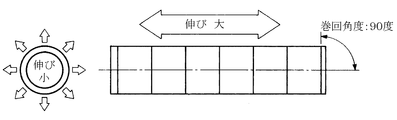
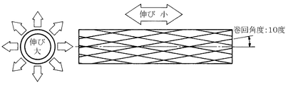
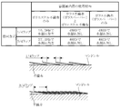
- the fiber layer in which the winding angle of the fiber is inclined with respect to the axial direction is called a helical layer in the FW method (see FIG. 1.
- FIG. 1 illustrates the case where the helical angle is 55 degrees. .
- the winding angle of the fibers forming the helical layer is not proof in the length direction even if proof only in the circumferential direction (for example, there is no change in the circumferential direction when pressure is applied to the FRP pressure vessel).
- the winding angle of the fiber is close to 90 degrees (see FIG. 2), or even if there is proof strength only in the length direction, there is no proof strength in the circumferential direction (for example, When pressure is applied to the FRP pressure vessel, there is no change in the length direction, but the inner diameter extends in the circumferential direction (for example, when the fiber winding angle is close to 0 degrees, see FIG. 3).
- the angle is a balance between the yield strength in the circumferential direction of the pressure vessel and the yield strength in the length direction (axial direction) with respect to the pressure.
- a fiber body (helical layer) having an angle of 55 degrees is wound and laminated to produce a tubular body.
- a large load force to push the closure lid out of the tube body by the internal pressure acts on the closure lids 2 at both ends of the tubular body provided at both ends of the pressure vessel.
- the layer of the wound laminate is made thicker (high rigidity) or a retainer Either a method of increasing the shear distance by increasing the distance from the ring to the end of the tube (whether the shearing force is increased) or the pressure vessel becomes heavy in any case.
- the body portion of the pipe body 51 is solid, and the proof strength of the internal pressure often depends on the proof strength of the FRP layer around the retainer ring.
- the industry standard ASME Section X (American Society e Mechanical Engineer Section X) stipulates that the breaking pressure (safety factor) due to internal pressure is more than 6 times the operating pressure.
- the orientation design (anisotropic design) greatly affects the quality of the pressure vessel.
- Patent Document 1 a hoop layer wound in the circumferential direction of the mandrel is provided in regions on both sides of the inner ring, and a helical layer wound in an acute angle with respect to the axial center direction of the mandrel is provided in other regions ( FIG. 1 of Patent Document 1) is disclosed (note that a hoop layer is further provided only at both ends of the helical layer).
- a so-called multi-port type pressure vessel is often used in which seawater is supplied into the pressure vessel from the side port on the side, and concentrated seawater generated by seawater desalination by reverse osmosis is discharged from the side port on the other end side.
- This multi-port type pressure vessel is rapidly spreading due to the effect that the pressure vessel has functions of supplying seawater and discharging concentrated seawater, and the number of metal pipes that are easily rusted can be reduced.
- this multi-port type pressure vessel can increase the amount of seawater and concentrated seawater flow as the openings (side port holes) at the 12 o'clock and 6 o'clock positions on both ends are increased.
- an 8-inch pressure vessel inner diameter of the tube: 202 mm
- an 11-inch pressure vessel inner diameter of the tube: 280 mm
- openings of 4 inches (101.6 mm) at both ends are available. .
- FRP has anisotropy, and a large proof stress is obtained by connecting the fibers. Furthermore, the cross-sectional shape of the FRP is cut by side port hole processing. If it does, the shape maintenance force of the part will be impaired. Furthermore, the larger the side port hole is with respect to the inner diameter of the tube, the more difficult it is to maintain its shape. Specifically, when a 4 inch side port hole is drilled at a 12 o'clock and 6 o'clock position on a pressure vessel having an inner diameter of 8 inches, the position of 12 o'clock to 6 o'clock is the short diameter, 3 o'clock in the cross section of the part.
- a water stop seal 54 for example, an O-ring having a circular cross section or a quad ring having an X cross section.
- the cross section of the water-stop seal portion of the tube 51 is an ellipse
- the cross-section of the water-stop seal portion of the closure lid 52 is a perfect circle
- the ellipse contacts the perfect circle.
- a difference in diameter between the perfect circle and the ellipse occurs in the major axis portion of this, water leakage (pressure leakage) occurs from this portion, and the function as a pressure vessel for seawater desalination is lost.
- the sealing performance and the internal pressure resistance in the vicinity of the closure lid of the pressure vessel are important functions in the pressure vessel for seawater desalination by the reverse osmosis membrane method.
- patent document 1 is disclosing the structure and structure which can obtain big proof strength with respect to an internal pressure, consideration is not made with respect to the elliptical deformation by opening of this pipe both ends.
- the body portion of the pressure vessel (generally, the section from the seal 54 of the closure lid 52 at one end to the seal 54 of the closure lid 52 at the other end) Similarly, sealability and resistance to internal pressure are required.
- the winding angle of the helical layer is set to 55 degrees in order to maintain the internal pressure, but only with glass fiber and matrix resin (for example, epoxy resin or unsaturated ester resin).
- glass fiber and matrix resin for example, epoxy resin or unsaturated ester resin.
- resistance to pressure can be obtained, but it is extremely difficult to prevent leakage of liquid (for example, seawater, concentrated seawater, or generated water obtained by reverse osmosis) inside the pressure vessel.
- FRP is composed of fiber and resin, but these exist separately when viewed microscopically and are uniform when viewed macroscopically.
- resin is buried between the fibers.
- leakage of the content liquid may occur using this cavity as an entrance.
- the cavity ratio of FRP is approximately 1 to 2%, and if this cavity is on the inner surface of the pressure vessel, there is a good possibility that it will be an entrance for leakage of the content liquid.
- the fiber angle of the helical layer is set to 55 degrees, so that it is sufficient to maintain the pressure (internal pressure resistance), but the fluid in the pressure vessel is externally There is an insufficient point (sealability) in that it does not leak.
- the fiber in the helical layer with a winding angle of 55 degrees has a certain fiber and a fiber adjacent to the fiber at 55 degrees.
- the fluid in the pressure vessel for example, in seawater desalination, (Dense seawater) enters the defect, and the pressure applied to the fluid is also applied, gradually eroding the interface between the fiber and the resin arranged at 55 degrees (eroding in the direction of 55 degrees). In the end, it will eventually become a “fluid leak”.
- a water passage may be formed toward the pressure vessel surface over a long time, like water contained in a mountain, and the liquid content may leak.
- the leakage of liquid not only impairs the pressure holding performance of the pressure vessel, but also disperses salt-containing liquids (seawater and concentrated seawater) into the seawater desalination plant (similar to a fountain because internal pressure is applied) causes serious problems such as corrosion to peripheral equipment.
- salt-containing liquids salt-containing liquids
- seawater desalination plants although there are no water leaks at the beginning of the installation, there are some pressure vessels where water leaks occur after 3 to 6 months for short ones and after 2 to 3 years for long ones.
- the sealing performance and the internal pressure resistance at the body portion of the pressure vessel are also important functions in the pressure vessel for seawater desalination by the reverse osmosis membrane method.
- the present invention has been made in view of the above-described situation, and can improve the sealing performance and internal pressure resistance in the vicinity of the closure lid and the body portion of the pressure vessel, and can also be deformed into an ellipse by drilling the side port. Therefore, the present invention provides a pressure vessel excellent in practicality capable of maintaining a high circular pressure of 800 to 1200 PSI while maintaining a perfect circular shape.
- An internal pressure vessel composed of a tubular body 1 formed by winding and laminating continuous fibers by a filament winding method, and used for seawater desalination treatment or pure water purification treatment by a reverse osmosis membrane method.
- Closed lids 2 for closing the tubular body 1 are provided at both ends in the body axis direction, and the tubular body 1 is provided on the inner surface of the closed lid 2 in the axial direction of the tubular body 1 on the circumferential surface of the tubular body 1.
- An introduction / extraction part 3 for introducing or deriving a fluid from the peripheral surface of the tube 1 is provided.
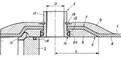
- the tubular body 1 includes a helical layer 4 formed by helically winding a fiber, a hoop layer formed by winding a fiber and a hoop.
- the seal layer 6 is provided on the inner layer, and at both ends of the tube body 1 in the axial direction of the tube body, the helical layer 4 is positioned at least from the outer side of the closing lid 2 in the axial direction of the tube body.
- the shim extends toward the inner side of the introduction / extraction part 3 in the axial direction of the tube.
- a separation portion 7 that is separated from the outer circumferential side of the steel layer 6 is provided, and the hoop layer is a first hoop layer 8 provided between the separation portion 7 of the helical layer 4 and the seal layer 6.
- a second hoop layer 9 provided on the outer periphery of the helical layer 4 from a position on the outer side in the tube axis direction of the closing lid 2 to a position on the inner side in the tube axis direction of the introduction / extraction part 3; It is related with the internal pressure container characterized by being comprised by these.
- the present invention relates to an internal pressure vessel.
- the resin content of the seal layer 6 is set to 40 to 85% by weight, and the resin content of the helical layer 4 and the hoop layer is set to 20 to 30% by weight.
- the present invention relates to an internal pressure vessel.
- the internal pressure container according to any one of claims 2 to 4, wherein the sealing layer 6 includes a layer made of a glass nonwoven fabric and the matrix resin. is there.
- the present invention relates to an internal pressure vessel characterized by comprising two sealing layers 11.
- the internal pressure container according to any one of claims 2 to 4, wherein the seal layer 6 is formed by continuously winding a tape-like base material around a mandrel. It concerns the internal pressure vessel.
- the portion other than the separation portion 7 of the helical layer 4 is in contact with the seal layer 6.
- the portion other than the separation portion 7 of the helical layer 4 is in contact with the seal layer 6.
- the portion other than the separation portion 7 of the helical layer 4 is in contact with the seal layer 6.
- the portion other than the separation portion 7 of the helical layer 4 is in contact with the seal layer 6.
- the portion other than the separation portion 7 of the helical layer 4 is in contact with the seal layer 6.
- the present invention since the present invention is configured as described above, it becomes a pressure vessel excellent in practicality capable of maintaining a high pressure of 800 to 1200 PSI while maintaining a perfect circular shape without being deformed into an ellipse even by drilling a side port.
- the separation state (swelling state) of the separation part 7 of the helical layer 4 is held by the first hoop layer 8 and the second hoop layer 9, so that not only the shearing force between the layers but also the fibers of the helical layer 4
- the strength is maintained even by the force that divides the pressure, and the pressure resistance in the vicinity of the closing lid of the pressure vessel can be improved without increasing the size and weight of the tube body 1.
- the helical layer 4 is sandwiched between the hoop layers 8 and 9 used to maintain the circular shape of the tubular body 1, and the fibers are cut by drilling (side port hole processing) of the inlet / outlet portion 3.
- the perfect circular shape of the tubular body 1 can be maintained by the first hoop layer 8 and the second hoop layer 9.
- both end portions of the helical layer 4 have an arch shape in a longitudinal sectional view, and in this respect as well, elliptical deformation due to drilling of the introduction / extraction portion 3 can be prevented. Therefore, it can prevent that the sealing performance of the obstruction
- the sealing layer 6 is composed of a base material having a random isotropic fiber orientation, and a matrix resin that is the same as the matrix resin of the helical layer 4 and the hoop layer, for example, a glass nonwoven fabric and an epoxy resin.
- a matrix resin that is the same as the matrix resin of the helical layer 4 and the hoop layer, for example, a glass nonwoven fabric and an epoxy resin.
- This example is a pressure vessel used for seawater desalination or pure water treatment by a reverse osmosis membrane method, comprising a tube 1 formed by winding and laminating continuous fibers by a filament winding method.
- Closed lids 2 for closing the tubular body 1 are provided at both ends of the tubular body 1 in the axial direction of the tubular body, and on the inner surface in the axial direction of the tubular lid 1 on the circumferential surface of the tubular body 1.
- the helical layer 4 has at least the axial direction of the tubular body of the closure lid 2. From the outer side position to the inner side position of the introduction / extraction part 3 in the axial direction of the tube Thus, a separation portion 7 that is separated from the seal layer 6 toward the outer side in the circumferential direction is provided, the helical layer 4 is provided on both the inside and outside of the separation portion 7 so as to be in contact with the seal layer 6, and the hoop layer is The hoop layer is provided only at both ends of the tubular body 1, and the hoop layer includes a first hoop layer 8 provided between the separation portion 7 of the helical layer 4 and the seal layer 6, and the helical layer 4. And a second hoop layer 9 provided from the outer side position in the tube axis direction of the closing lid 2 to the inner side position in the tube axis direction of the introduction /
- the tubular body 1 of the present embodiment is formed of a glass fiber impregnated with an epoxy resin and a resin containing these curing agents by a known filament winding method (a layer to be a seal layer 6 described later is formed). The required amount is continuously wound around the mandrel at a predetermined inclination angle with respect to the axial direction of the mandrel (the axial direction of the tube 1), the epoxy resin is heated and cured, and then the mandrel is removed.
- a tape-shaped base material having a random isotropic fiber orientation and a predetermined wrap (1 / 4) to 3/4), and continuously wound around a mandrel and impregnated with a matrix resin to form a resin-impregnated layer to be the seal layer 6, and on the resin-impregnated layer to be the seal layer 6
- a helical layer 4 and a resin-impregnated layer serving as a hoop layer are provided.
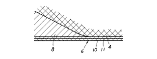
- a glass nonwoven fabric is continuously wound around a mandrel and a resin-impregnated layer is provided as a first seal layer 10 impregnated with an epoxy resin, and then the polyester nonwoven fabric is continuously applied to the mandrel.
- a resin-impregnated layer that becomes the second seal layer 11 that is wound and impregnated with an epoxy resin is provided.
- the innermost layer is a sealing layer using a glass nonwoven fabric, but the polyester nonwoven fabric may be wound first, and the glass nonwoven fabric may be wound later (seal using a polyester nonwoven fabric for the innermost layer). It may be a layer.) Moreover, you may employ
- glass fiber has developed surface treatment technology, and the adhesion between the fiber surface and the epoxy resin is good.
- Organic fibers such as polyester are cured of epoxy resin (crosslinking, polymerization, etc.). It is said that it is difficult to bond the fiber surface to the epoxy resin due to the reaction inhibiting factor.
- Polyester fibers, as represented by fleece, have the feature that the bulk can be increased in the same basis weight, and therefore can contain a large amount of resin (there is a property that the resin can be contained in the bulky void portion).
- the combination of glass and polyester fabrics complements each other's drawbacks.
- composition of this combination is a polyester unwoven cloth that can contain more resin than a glass unwoven cloth layer and a glass unwoven cloth with good adhesion between epoxy resin and glass fiber. Can be combined with each other to obtain a good sealing layer (water blocking layer against water leakage).
- a resin-impregnated layer that becomes the first hoop layer 8 is formed by hoop winding of ⁇ 89 degrees, and then the resin that becomes the helical layer 4 is formed by helical winding of 50 degrees to 60 degrees over the entire axial direction of the tube 1.
- the impregnated layer is formed, and then the helical layer 4 is separated from the inner end of the first hoop layer 8 from the end of the tube 1 in the axial direction of the tube (the separated helical layer 4 is the seal layer 6.
- a resin-impregnated layer that becomes the second hoop layer 9 is formed by hoop winding at 85 to 89 degrees (inward side position of the portion in contact with the substrate). Thereafter, each resin-impregnated layer is cured by heating, and the mandrel is decentered (demolded) to obtain the tubular body 1.
- the first hoop layer 8 may have a starting point at a position away from the outer end portion of the closing lid 2 by a predetermined distance, and an end point thereof as the inner end portion position of the introduction / extraction portion 3 (introduction). What is necessary is just to set to the position where the hole periphery does not deform
- the resin content of the heat-cured seal layer 6 (first seal layer 10 and second seal layer 11) is 40 to 85% by weight
- the helical layer 4 and the hoop layer (first The resin content of the hoop layer 8 and the second hoop layer 9) is set to 20 to 30% by weight.
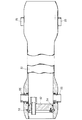
- both ends of the tube body 1 are provided with a closure lid 2 made of fiber reinforced resin (made of FRP) having the same diameter as the inner peripheral surface of the tube body 1, as shown in FIGS.
- the FRP retainer ring 12 disposed in the concave portion provided on the peripheral surface is closed by joining with a bolt 13.
- reference numeral 14 denotes an O-ring that closes the gap between the closing lid 2 and the inner peripheral surface of the tube 1
- 15 denotes a communication hole that communicates the inside and the outside of the tube 1.
- positioned is only by cutting the inner peripheral surface (first hoop layer 8) of the pipe body 1, and forming a ditch
- An introduction / extraction portion 3 (side port) is provided in the proximity state on the inner side in the axial direction of the tube body 1 of the closing lid 2.
- the introduction / extraction part 3 is composed of an introduction / extraction hole drilled in the peripheral surface of the tube 1 and a cylindrical body 17 provided in the introduction / extraction hole and having a flange 16 on one end side.
- the 17 flange portions 16 are engaged with the step portions 18 provided on the inner peripheral surface of the tubular body 1.
- reference numeral 19 denotes a snap ring for locking the cylindrical body 17 to the pipe body 1
- 20 denotes an O-ring.
- the helical layer 4 is disposed on the outer side in the circumferential direction (outside the radial direction) from the seal layer 6 in the vicinity of the closing lid 2 and the introduction / extraction portion 3 provided in the proximity state. It is in a state where it is separated (escape) and bent in an arch shape, and is in contact with the seal layer 6 (second seal layer 11) except for the separation portion 7.
- both end portions of the helical layer 4 are sandwiched between the first hoop layer 8 and the second hoop layer 9 (so-called side switch structure), and the arch shape of the separation portion 7 of the helical layer 4 is maintained. Therefore, in addition to the effect of maintaining the perfect circular shape by the two hoop layers existing around the introduction / exit portion 3, the helical layer 4 itself is also difficult to be elliptically deformed. Is maintained well (the first hoop layer 8 and the second hoop layer 9 form a sandwich structure so that the round shape of the cross section that is a characteristic of the hoop layer is maintained). Therefore, the water stop effect by the O-ring 14 of the closing lid 2 is satisfactorily exhibited. Further, the rising angles at both ends of the separation portion 7 of the helical layer 4 are set to 90 degrees or less.
- the inner end portion of the first hoop layer 8 (separation portion 7) at a position as far as possible from the introduction / extraction portion 3. Specifically, when the inner diameter of the tube 1 is 8, 10, or 16 inches, the first from the center of the port according to the inner diameter D (port inner diameter) of the cylindrical body 17 of the introduction / extraction portion 3 regardless of the inner diameter. The distance L to the inner end of the hoop layer 8 (separation part 7) is set.
- L is 70 mm
- L is 100 mm
- L is 150 mm
- D is 4 inches
- L is
- L is
- L is
- L is preferably set to 300 mm
- D is 8 inches
- L is preferably set to 400 mm. Therefore, for example, L per D1 inch may be set to 50 mm or more.
- the separation state (swell state) of the separation portion 7 of the helical layer 4 is held by the first hoop layer 8 and the second hoop layer 9, so that each layer
- the strength is maintained not only by the shearing force of the tube but also by the force of breaking the fibers of the helical layer 4, so that the pressure resistance in the vicinity of the closure lid of the pressure vessel is not increased without increasing the size and weight of the tube body 1. It becomes possible to improve the property.
- the helical layer 4 is sandwiched between the hoop layers 8 and 9 used for maintaining the perfect circular shape of the tube body 1, and even if the fiber is cut by the hole processing of the introduction / extraction portion 3 (side port).
- the perfect circular shape of the tubular body 1 can be maintained by the first hoop layer 8 and the second hoop layer 9.
- both ends of the helical layer 4 have an arch shape in the longitudinal sectional view due to the presence of the separation portion 7 of the helical layer 4.
- the elliptical deformation due to the hole processing of the introduction / extraction portion 3 can be prevented, and the helical layer 4
- the retainer ring is gripped (a structure in which both hands hold the flat plate), and the force that maintains the axial pressure in the axial direction of the tube works. Therefore, it is possible to prevent the sealing performance in the vicinity of the closing lid 2 from being damaged by the side port hole processing and to secure the internal pressure resistance.
- a hoop layer (a sandwich structure composed of both the first hoop layer 8 and the second hoop layer 9 and the both) has a positive cross section.
- the shape of the circle is maintained, the internal pressure resistance in the circumferential direction is ensured, and further, the internal pressure resistance in the longitudinal direction is achieved by the structure that holds the retainer ring that is the pressure support part to the tube body by undulating the helical layer It is to secure the sex.
- a firm water-stopping layer can be formed by the innermost layer, and the sealing performance at the container body portion is improved.
- this embodiment is excellent in practicality that can maintain a high pressure of 800 to 1200 PSI while maintaining a perfect circular shape without being deformed into an ellipse even by drilling a side port.
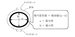
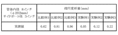
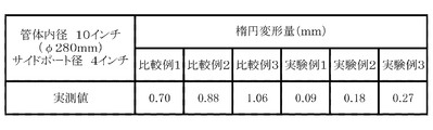
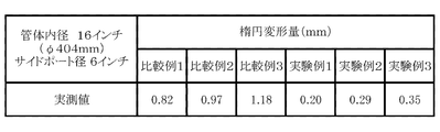
- FIGS. 11 to 13 show experimental examples 1 to 3 having the same structure as the above-described embodiment, each having a different inner diameter of the tube, and a comparative example of a conventional structure having no separation portion as shown in FIG.
- the results of measuring the elliptical deformation amounts 1 to 3 are shown. Note that the allowable value of the elliptical deformation amount with respect to water leakage is 0.4 mm, and the elliptical deformation amount is obtained from “absolute value (ab)” as shown in FIG.
Landscapes
- Engineering & Computer Science (AREA)
- Chemical & Material Sciences (AREA)
- General Engineering & Computer Science (AREA)
- Mechanical Engineering (AREA)
- Chemical Kinetics & Catalysis (AREA)
- Water Supply & Treatment (AREA)
- Nanotechnology (AREA)
- Composite Materials (AREA)
- Pressure Vessels And Lids Thereof (AREA)
- Moulding By Coating Moulds (AREA)
- Separation Using Semi-Permeable Membranes (AREA)
- Filling Or Discharging Of Gas Storage Vessels (AREA)
Priority Applications (6)
| Application Number | Priority Date | Filing Date | Title |
|---|---|---|---|
| ES12852893T ES2805335T3 (es) | 2011-12-02 | 2012-09-07 | Recipiente a presión interna para desalinización de agua de mar |
| EP12852893.2A EP2787254B1 (en) | 2011-12-02 | 2012-09-07 | Internal pressure vessel for seawater dessalination |
| IN3904CHN2014 IN2014CN03904A (enExample) | 2011-12-02 | 2012-09-07 | |
| US14/361,964 US9109752B2 (en) | 2011-12-02 | 2012-09-07 | Internal pressure vessel |
| AU2012345220A AU2012345220C1 (en) | 2011-12-02 | 2012-09-07 | Internal pressure vessel |
| SG11201402521SA SG11201402521SA (en) | 2011-12-02 | 2012-09-07 | Internal pressure vessel |
Applications Claiming Priority (2)
| Application Number | Priority Date | Filing Date | Title |
|---|---|---|---|
| JP2011264541A JP5400125B2 (ja) | 2011-12-02 | 2011-12-02 | 内圧容器 |
| JP2011-264541 | 2011-12-02 |
Publications (1)
| Publication Number | Publication Date |
|---|---|
| WO2013080623A1 true WO2013080623A1 (ja) | 2013-06-06 |
Family
ID=48535100
Family Applications (1)
| Application Number | Title | Priority Date | Filing Date |
|---|---|---|---|
| PCT/JP2012/072893 Ceased WO2013080623A1 (ja) | 2011-12-02 | 2012-09-07 | 内圧容器 |
Country Status (8)
| Country | Link |
|---|---|
| US (1) | US9109752B2 (enExample) |
| EP (1) | EP2787254B1 (enExample) |
| JP (1) | JP5400125B2 (enExample) |
| AU (1) | AU2012345220C1 (enExample) |
| ES (1) | ES2805335T3 (enExample) |
| IN (1) | IN2014CN03904A (enExample) |
| SG (1) | SG11201402521SA (enExample) |
| WO (1) | WO2013080623A1 (enExample) |
Cited By (4)
| Publication number | Priority date | Publication date | Assignee | Title |
|---|---|---|---|---|
| WO2015044783A2 (en) | 2013-09-26 | 2015-04-02 | Alto Solution Sa | Self supporting structure |
| WO2016151408A2 (en) | 2015-03-25 | 2016-09-29 | Alto Solution Sa | Self supporting structure |
| JP2019152267A (ja) * | 2018-03-02 | 2019-09-12 | 三菱重工業株式会社 | 水中構造体 |
| WO2020184661A1 (ja) * | 2019-03-12 | 2020-09-17 | 旭化成株式会社 | ろ過方法、海水を淡水化する方法、淡水を製造する方法、中空糸膜モジュール、および海水淡水化システム |
Families Citing this family (8)
| Publication number | Priority date | Publication date | Assignee | Title |
|---|---|---|---|---|
| JP5400125B2 (ja) | 2011-12-02 | 2014-01-29 | 株式会社有沢製作所 | 内圧容器 |
| JP6146331B2 (ja) * | 2014-02-10 | 2017-06-14 | トヨタ自動車株式会社 | タンク |
| JP6597530B2 (ja) * | 2016-09-09 | 2019-10-30 | トヨタ自動車株式会社 | 高圧タンクの製造方法 |
| JP6448605B2 (ja) * | 2016-11-21 | 2019-01-09 | 株式会社有沢製作所 | 圧力容器 |
| JP6922393B2 (ja) * | 2017-05-09 | 2021-08-18 | 三菱ケミカル株式会社 | 圧力容器 |
| JP7197260B2 (ja) * | 2017-09-12 | 2022-12-27 | 旭化成株式会社 | 中空糸膜モジュール、海水淡水化システム、海水を淡水化する方法、海水より淡水を製造する方法、中空糸膜モジュールの運転方法、ろ過方法、および中空糸膜モジュールの製造方法 |
| JP7376397B2 (ja) * | 2019-03-12 | 2023-11-08 | 旭化成株式会社 | ろ過方法および中空糸膜モジュール |
| US12599876B2 (en) * | 2022-12-13 | 2026-04-14 | Air Products And Chemicals, Inc. | Port for membrane module |
Citations (7)
| Publication number | Priority date | Publication date | Assignee | Title |
|---|---|---|---|---|
| JPS52126515A (en) * | 1976-04-15 | 1977-10-24 | Gudarieuitsuchi Pimush Bayooru | Multiilayered pressure tanks |
| JPS58106259A (ja) * | 1981-12-03 | 1983-06-24 | メツセルシユミツト−ベルコウ−ブロ−ム・ゲゼルシヤフト・ミト・ベシユレンクテル・ハフツング | 複合材料からなる円環状の圧力容器 |
| JPH06137433A (ja) * | 1992-01-10 | 1994-05-17 | Brunswick Corp | フィラメント巻付け式圧力容器のための改良したボス |
| JPH09178097A (ja) * | 1995-12-28 | 1997-07-11 | Arisawa Mfg Co Ltd | 内圧容器及びその製造方法 |
| JP2000015711A (ja) * | 1998-07-06 | 2000-01-18 | Nissan Motor Co Ltd | 圧力容器用補強部材の製造方法および製造装置 |
| JP2006015573A (ja) * | 2004-06-30 | 2006-01-19 | Arisawa Mfg Co Ltd | 内圧容器及びその製造方法 |
| JP2008535695A (ja) * | 2005-04-11 | 2008-09-04 | ベカルト プログレッシブ コンポジッツ,リミテッド ライアビリティー カンパニー | 側部ポート付きのフィラメント巻き圧力容器 |
Family Cites Families (6)
| Publication number | Priority date | Publication date | Assignee | Title |
|---|---|---|---|---|
| DE2035541A1 (en) * | 1970-07-17 | 1972-01-20 | Dynamit Nobel Ag | Vessel cladding - using studs as anchor points to give winding angle for even coverage in rocket motor systems |
| US5429845A (en) | 1992-01-10 | 1995-07-04 | Brunswick Corporation | Boss for a filament wound pressure vessel |
| US20030121842A1 (en) * | 2001-08-21 | 2003-07-03 | Membrane Concepts, S.L. | Encapsulated filter unit, system and method for filtering fluids |
| JP4865833B2 (ja) * | 2009-04-30 | 2012-02-01 | 三菱重工業株式会社 | 圧力変換器用の管体 |
| US8377298B2 (en) * | 2010-02-10 | 2013-02-19 | Enpress, LLC | Housing for reverse osmosis filter cartridge and method of forming same |
| JP5400125B2 (ja) | 2011-12-02 | 2014-01-29 | 株式会社有沢製作所 | 内圧容器 |
-
2011
- 2011-12-02 JP JP2011264541A patent/JP5400125B2/ja active Active
-
2012
- 2012-09-07 WO PCT/JP2012/072893 patent/WO2013080623A1/ja not_active Ceased
- 2012-09-07 IN IN3904CHN2014 patent/IN2014CN03904A/en unknown
- 2012-09-07 US US14/361,964 patent/US9109752B2/en active Active
- 2012-09-07 SG SG11201402521SA patent/SG11201402521SA/en unknown
- 2012-09-07 EP EP12852893.2A patent/EP2787254B1/en active Active
- 2012-09-07 AU AU2012345220A patent/AU2012345220C1/en active Active
- 2012-09-07 ES ES12852893T patent/ES2805335T3/es active Active
Patent Citations (8)
| Publication number | Priority date | Publication date | Assignee | Title |
|---|---|---|---|---|
| JPS52126515A (en) * | 1976-04-15 | 1977-10-24 | Gudarieuitsuchi Pimush Bayooru | Multiilayered pressure tanks |
| JPS58106259A (ja) * | 1981-12-03 | 1983-06-24 | メツセルシユミツト−ベルコウ−ブロ−ム・ゲゼルシヤフト・ミト・ベシユレンクテル・ハフツング | 複合材料からなる円環状の圧力容器 |
| JPH06137433A (ja) * | 1992-01-10 | 1994-05-17 | Brunswick Corp | フィラメント巻付け式圧力容器のための改良したボス |
| JPH09178097A (ja) * | 1995-12-28 | 1997-07-11 | Arisawa Mfg Co Ltd | 内圧容器及びその製造方法 |
| JP2000015711A (ja) * | 1998-07-06 | 2000-01-18 | Nissan Motor Co Ltd | 圧力容器用補強部材の製造方法および製造装置 |
| JP2006015573A (ja) * | 2004-06-30 | 2006-01-19 | Arisawa Mfg Co Ltd | 内圧容器及びその製造方法 |
| JP4219862B2 (ja) | 2004-06-30 | 2009-02-04 | 株式会社有沢製作所 | 内圧容器 |
| JP2008535695A (ja) * | 2005-04-11 | 2008-09-04 | ベカルト プログレッシブ コンポジッツ,リミテッド ライアビリティー カンパニー | 側部ポート付きのフィラメント巻き圧力容器 |
Cited By (11)
| Publication number | Priority date | Publication date | Assignee | Title |
|---|---|---|---|---|
| WO2015044783A2 (en) | 2013-09-26 | 2015-04-02 | Alto Solution Sa | Self supporting structure |
| US10130915B2 (en) | 2013-09-26 | 2018-11-20 | Alto Solution Sa | Self supporting structure for membrane crossflow cartridges |
| WO2016151408A2 (en) | 2015-03-25 | 2016-09-29 | Alto Solution Sa | Self supporting structure |
| JP2019152267A (ja) * | 2018-03-02 | 2019-09-12 | 三菱重工業株式会社 | 水中構造体 |
| WO2020184661A1 (ja) * | 2019-03-12 | 2020-09-17 | 旭化成株式会社 | ろ過方法、海水を淡水化する方法、淡水を製造する方法、中空糸膜モジュール、および海水淡水化システム |
| KR20210126091A (ko) * | 2019-03-12 | 2021-10-19 | 아사히 가세이 가부시키가이샤 | 여과 방법, 해수를 담수화하는 방법, 담수를 제조하는 방법, 중공사막 모듈, 및 해수 담수화 시스템 |
| CN113557077A (zh) * | 2019-03-12 | 2021-10-26 | 旭化成株式会社 | 过滤方法、海水淡化方法、淡水制造方法、中空纤维膜组件以及海水淡化系统 |
| JPWO2020184661A1 (ja) * | 2019-03-12 | 2021-12-02 | 旭化成株式会社 | ろ過方法、海水を淡水化する方法、淡水を製造する方法、中空糸膜モジュール、および海水淡水化システム |
| JP7111885B2 (ja) | 2019-03-12 | 2022-08-02 | 旭化成株式会社 | ろ過方法、海水を淡水化する方法、淡水を製造する方法、中空糸膜モジュール、および海水淡水化システム |
| CN113557077B (zh) * | 2019-03-12 | 2023-09-12 | 旭化成株式会社 | 过滤方法、海水淡化方法、淡水制造方法、中空纤维膜组件以及海水淡化系统 |
| KR102597942B1 (ko) | 2019-03-12 | 2023-11-02 | 아사히 가세이 가부시키가이샤 | 여과 방법, 해수를 담수화하는 방법, 담수를 제조하는 방법, 중공사막 모듈, 및 해수 담수화 시스템 |
Also Published As
| Publication number | Publication date |
|---|---|
| JP2013117250A (ja) | 2013-06-13 |
| EP2787254A4 (en) | 2015-10-07 |
| SG11201402521SA (en) | 2014-08-28 |
| AU2012345220C1 (en) | 2015-12-17 |
| US9109752B2 (en) | 2015-08-18 |
| AU2012345220B2 (en) | 2015-08-13 |
| EP2787254B1 (en) | 2020-06-10 |
| JP5400125B2 (ja) | 2014-01-29 |
| US20140339239A1 (en) | 2014-11-20 |
| IN2014CN03904A (enExample) | 2015-10-16 |
| ES2805335T3 (es) | 2021-02-11 |
| EP2787254A1 (en) | 2014-10-08 |
| AU2012345220A1 (en) | 2014-06-05 |
Similar Documents
| Publication | Publication Date | Title |
|---|---|---|
| JP5400125B2 (ja) | 内圧容器 | |
| US10400956B2 (en) | Boss seal for composite overwrapped pressure vessel | |
| US8397938B2 (en) | Clamped liner-boss connection | |
| US8820361B2 (en) | Tube body for pressure transducer | |
| CN110848569B (zh) | 一种非金属内胆纤维缠绕气瓶的瓶口连接部 | |
| JP6448605B2 (ja) | 圧力容器 | |
| CN115325433B (zh) | 塑料内衬纤维增强复合材料高压气瓶密封结构 | |
| JP4959625B2 (ja) | 繊維強化樹脂製の管体 | |
| RU2154220C1 (ru) | Пластмассовая труба | |
| JP7695748B2 (ja) | 水素透過によるブリスターを防止する複合管及びその設計方法、水素パイプライン網 | |
| CN219263931U (zh) | 一种塑料内衬纤维增强复合材料高压气瓶多级密封结构 | |
| CN204573359U (zh) | 一种大口径超高分子量聚乙烯片材复合管材 | |
| JP2015184088A (ja) | 計器取付け用配管継手、計器取付け用配管継手構造および計器取付け用配管継手を用いた漏水防止方法 | |
| JP6573322B2 (ja) | 合成樹脂製パイプ | |
| JP2005111737A (ja) | 内張り材の拡張チューブ |
Legal Events
| Date | Code | Title | Description |
|---|---|---|---|
| 121 | Ep: the epo has been informed by wipo that ep was designated in this application |
Ref document number: 12852893 Country of ref document: EP Kind code of ref document: A1 |
|
| WWE | Wipo information: entry into national phase |
Ref document number: 14361964 Country of ref document: US |
|
| NENP | Non-entry into the national phase |
Ref country code: DE |
|
| ENP | Entry into the national phase |
Ref document number: 2012345220 Country of ref document: AU Date of ref document: 20120907 Kind code of ref document: A |
|
| WWE | Wipo information: entry into national phase |
Ref document number: 2012852893 Country of ref document: EP |