WO2013073695A1 - Alliage métallique solide - Google Patents
Alliage métallique solide Download PDFInfo
- Publication number
- WO2013073695A1 WO2013073695A1 PCT/JP2012/079871 JP2012079871W WO2013073695A1 WO 2013073695 A1 WO2013073695 A1 WO 2013073695A1 JP 2012079871 W JP2012079871 W JP 2012079871W WO 2013073695 A1 WO2013073695 A1 WO 2013073695A1
- Authority
- WO
- WIPO (PCT)
- Prior art keywords
- silver
- alloy
- nickel
- analysis
- fluid
- Prior art date
Links
Images


Classifications
-
- C—CHEMISTRY; METALLURGY
- C22—METALLURGY; FERROUS OR NON-FERROUS ALLOYS; TREATMENT OF ALLOYS OR NON-FERROUS METALS
- C22C—ALLOYS
- C22C19/00—Alloys based on nickel or cobalt
- C22C19/03—Alloys based on nickel or cobalt based on nickel
-
- B—PERFORMING OPERATIONS; TRANSPORTING
- B22—CASTING; POWDER METALLURGY
- B22F—WORKING METALLIC POWDER; MANUFACTURE OF ARTICLES FROM METALLIC POWDER; MAKING METALLIC POWDER; APPARATUS OR DEVICES SPECIALLY ADAPTED FOR METALLIC POWDER
- B22F1/00—Metallic powder; Treatment of metallic powder, e.g. to facilitate working or to improve properties
- B22F1/05—Metallic powder characterised by the size or surface area of the particles
- B22F1/054—Nanosized particles
-
- B—PERFORMING OPERATIONS; TRANSPORTING
- B22—CASTING; POWDER METALLURGY
- B22F—WORKING METALLIC POWDER; MANUFACTURE OF ARTICLES FROM METALLIC POWDER; MAKING METALLIC POWDER; APPARATUS OR DEVICES SPECIALLY ADAPTED FOR METALLIC POWDER
- B22F9/00—Making metallic powder or suspensions thereof
- B22F9/16—Making metallic powder or suspensions thereof using chemical processes
- B22F9/18—Making metallic powder or suspensions thereof using chemical processes with reduction of metal compounds
- B22F9/24—Making metallic powder or suspensions thereof using chemical processes with reduction of metal compounds starting from liquid metal compounds, e.g. solutions
-
- B—PERFORMING OPERATIONS; TRANSPORTING
- B82—NANOTECHNOLOGY
- B82Y—SPECIFIC USES OR APPLICATIONS OF NANOSTRUCTURES; MEASUREMENT OR ANALYSIS OF NANOSTRUCTURES; MANUFACTURE OR TREATMENT OF NANOSTRUCTURES
- B82Y30/00—Nanotechnology for materials or surface science, e.g. nanocomposites
-
- C—CHEMISTRY; METALLURGY
- C22—METALLURGY; FERROUS OR NON-FERROUS ALLOYS; TREATMENT OF ALLOYS OR NON-FERROUS METALS
- C22C—ALLOYS
- C22C12/00—Alloys based on antimony or bismuth
-
- C—CHEMISTRY; METALLURGY
- C22—METALLURGY; FERROUS OR NON-FERROUS ALLOYS; TREATMENT OF ALLOYS OR NON-FERROUS METALS
- C22C—ALLOYS
- C22C13/00—Alloys based on tin
-
- C—CHEMISTRY; METALLURGY
- C22—METALLURGY; FERROUS OR NON-FERROUS ALLOYS; TREATMENT OF ALLOYS OR NON-FERROUS METALS
- C22C—ALLOYS
- C22C5/00—Alloys based on noble metals
- C22C5/02—Alloys based on gold
-
- C—CHEMISTRY; METALLURGY
- C22—METALLURGY; FERROUS OR NON-FERROUS ALLOYS; TREATMENT OF ALLOYS OR NON-FERROUS METALS
- C22C—ALLOYS
- C22C5/00—Alloys based on noble metals
- C22C5/06—Alloys based on silver
-
- C—CHEMISTRY; METALLURGY
- C22—METALLURGY; FERROUS OR NON-FERROUS ALLOYS; TREATMENT OF ALLOYS OR NON-FERROUS METALS
- C22C—ALLOYS
- C22C5/00—Alloys based on noble metals
- C22C5/06—Alloys based on silver
- C22C5/08—Alloys based on silver with copper as the next major constituent
-
- C—CHEMISTRY; METALLURGY
- C22—METALLURGY; FERROUS OR NON-FERROUS ALLOYS; TREATMENT OF ALLOYS OR NON-FERROUS METALS
- C22C—ALLOYS
- C22C9/00—Alloys based on copper
Definitions
- the present invention relates to a novel solid metal alloy.
- alloys particularly alloys containing noble metals such as gold and silver, are attracting attention as being used for various purposes in technical fields where high technology and nanotechnology can be applied.
- silver and copper alloy particles as materials used for conductive paste, conductive ink, conductive fine wiring, etc., or materials used for reduction catalyst of carbon monoxide and nitrogen oxide (NO x ), lead-free solder, etc. Is attracting attention.
- the characteristics may be controlled by the ratio of silver and copper in the silver-copper alloy particles.
- the main alloy is formed by alloying silver with excellent resistivity and oxidation resistance with copper for suppressing silver migration.
- silver-copper alloy particles mainly made of copper are attracting attention as silver-copper alloy particles made of silver and wiring materials such as magnet wires.
- silver-copper alloys are a material that is required in a wide range of industries.
- Migration occurs in many metals, but silver migration is known to occur quickly, and it is said that migration can be delayed by alloying with other metals such as copper.
- the properties expected of a silver-copper alloy such as suppression of oxidizable properties of copper and suppression of silver migration, are often not fully exhibited. .
- silver and nickel alloy particles are also attracting attention as materials for use in conductive pastes, conductive inks, conductive fine wiring, contact materials and electrode materials, fuses and catalysts. Properties may be controlled by the ratio of silver to nickel in silver-nickel alloy particles, for example, high arc discharge erosion compared to single silver even in silver-nickel alloys where silver and nickel are not uniformly mixed It is known that resistance is exhibited, and heat resistance, wear resistance, welding resistance, catalytic performance, life as a spark plug, and the like are improved. Therefore, a silver nickel alloy is a material required in a wide range in the industry. However, since silver and nickel do not mix with each other uniformly, the characteristics expected as the above-mentioned silver-nickel alloy are often not fully exhibited.
- gold and nickel alloy particles are attracting attention as materials used for magnetic sensors, electrode materials, capacitors, catalysts, contact materials, and the like. May be able to control the characteristics by the rate of gold and nickel gold nickel alloy particles, for example, a state in which gold and nickel are not mixed uniformly even gold-nickel alloy, as an electronic component as compared to single gold It is known that performance as a highly reliable electrical contact material such as a connector, a small relay, and a printed wiring board is exhibited, and performance such as heat resistance, wear resistance, and catalyst performance is improved. Therefore, the gold-nickel alloy is a material required in a wide range in the industry. However, since gold and nickel form a eutectic as in the case of an alloy of silver and copper, it is difficult to form a solid solution. Therefore, there are many cases where the characteristics expected as the gold-nickel alloy are not sufficiently exhibited.
- Silver antimony alloys have been attracting attention as a material used for recording media, low-temperature brazing materials, superconducting materials, electrode materials, and the like. It might be able to control the characteristics by the proportion of the silver of the silver antimony alloy (Ag) and antimony (Sb), for example, even in a silver antimony alloy in a state where silver and antimony are not mixed uniformly, a single It is known that wear resistance and the like are improved compared to silver. Therefore, a silver antimony alloy is a material required in a wide field in the industry. However, the silver and antimony, in the above certain concentration to form a eutectic or intermetallic compounds, since immiscible with each other uniformly, often expected characteristics as the silver antimony alloy is not sufficiently exhibited .
- a solid alloy containing at least two kinds of metals there are two kinds of metals in various forms, but in the equilibrium diagram, the at least two kinds of metals have a eutectic structure, It is shown that there is a specific region of the solid phase that is unevenly distributed without being mixed with each other, such as by forming an intermetallic compound. In such a specific region, the two or more kinds of metals constituting the alloy show an uneven distribution state in which the component ratio of the whole alloy and the component ratios of the two kinds of metals in a minute range of nano level are greatly different, As a result, the properties expected as an alloy are often not fully exhibited.
- Patent Document 1 discloses silver-core silver-copper shell nanoparticles, and describes the silver-copper alloy constituting the shell from elemental composition analysis combining electron microscope observation and energy dispersive X-ray fluorescence measurement. There are doubts about the solid solution of silver and copper, such as the mapping of silver and copper in the shell is not disclosed.
- Patent Document 4 diffuses silver into copper particles by heat-treating silver-coated copper powder obtained by depositing silver on the surface of copper particles at a temperature of 150 to 600 ° C. in a non-oxidizing atmosphere.
- the silver diffusion copper powder obtained by making it be described is described.
- silver diffused copper powder is produced by diffusion of metallic silver from the copper particle surface, it is difficult to diffuse silver to the center of the copper particle, and the entire particle should be free of eutectic. In addition to being difficult, the particle size is too large for use as a paste.
- the metallic silver existing as a simple substance on the surface of the copper particles by the heat treatment can only be confirmed by the surface observation (SEM observation). There may also be copper present. From these, the silver-copper alloy is an alloy when viewed macroscopically, but cannot be called an alloy when viewed microscopically. *
- a powder metallurgy method As a method for producing silver and nickel alloy particles, a powder metallurgy method is generally used. However, a liquid phase reduction method as described in Patent Document 7, an atomization method as described in Patent Document 8, and the like. There is. However, the silver-nickel alloy produced by any of the above methods is not a uniform mixture of silver and nickel, and silver-nickel alloy particles substantially free of eutectic and a method for producing the same have been disclosed so far. Absent. In addition, there is a method of obtaining a solid solution of silver-nickel alloy particles by quenching from a state where metallic silver and metallic nickel are dissolved at a high temperature, but since high energy is required, the cost naturally increases. There are problems such as easy.
- a powder metallurgy method is generally used as a method for producing gold and nickel alloy particles, but there are a liquid phase reduction method described in Patent Document 9 and an atomization method described in Patent Document 10.
- a gold-nickel alloy in which gold and nickel are uniformly mixed, particularly gold-nickel alloy particles and a method for producing the same have not been disclosed so far.
- an alloy plating method as shown in Patent Document 11 As a method for producing an alloy of silver and antimony, an alloy plating method as shown in Patent Document 11 is generally used. As another production method, there is a method of producing alloy particles of silver and antimony using a mechanical alloying process as shown in Patent Document 12. However, the silver antimony alloy produced by these production methods contains a eutectic or an intermetallic compound, and a silver antimony alloy mixed uniformly has not been disclosed so far.
- a metal silver and antimony metal is cooled or quenched from a molten state at high temperature, it can be considered a method of obtaining a partial solid solution, the disclosure of silver antimony alloy mainly composed of non-eutectic structure, such as a solid solution
- the disclosure of silver antimony alloy mainly composed of non-eutectic structure such as a solid solution
- Patent Document 5 filed by the applicant of the present application, a method for producing silver-copper alloy particles was provided.
- Comparative Examples A1 to A3 described below were obtained.
- Patent Document 5 is a thin film fluid formed between at least two processing surfaces that are disposed opposite to each other and are capable of approaching / separating at least one rotating relative to the other. This is an apparatus for depositing fine particles, and is an apparatus expected to be used particularly for the production of nano-sized particles. The inventor of the present application has attempted to produce various nanoparticles using this apparatus, but not all of the relationship between the precipitation and reaction conditions and results has been elucidated.
- the solid metal alloy particles it was confirmed that the TEM-EDS analysis result and the ICP analysis result of one point for the platinum-palladium alloy almost coincided with each other. It was a solid solution type metal as shown in FIG.
- silver-copper alloy silver-copper alloy particles in which a eutectic or a single silver or copper is mixed have been obtained.
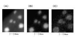
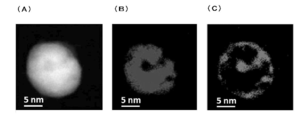
- FIG. 54A shows a STEM-HAADF image
- FIG. 54B shows an EELS mapping result (Ag)
- FIG. 54C shows an EELS mapping result (Cu).
- an energy dispersive X-ray analyzer Centurio (manufactured by JEOL)
- atomic resolution analytical electron microscope JEM-ARM200F (manufactured by JEOL) Acceleration Voltage: 200.0KV
- magnification: 6,000,000 is obtained by using.
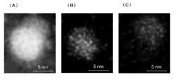
- 55A shows a STEM-HAADF image
- FIG. 55B shows a STEM mapping result (Ag)
- FIG. 55C shows a STEM mapping result (Cu).
- FIG. 55A shows a STEM-HAADF image
- FIG. 55B shows a STEM mapping result (Ag)
- FIG. 55C shows a STEM mapping result (Cu).
- an ultra-high resolution STEM analyzer equipped with Hitachi Cs collector (equipped with EDX): HD-2700 (manufactured by Hitachi High-Technologies) accelerating voltage: 200.0 kV and magnification: 22.000 are used.
- 56A shows a STEM-HAADF image
- FIG. 56B shows a STEM mapping result (Ag)
- FIG. 56C shows a STEM mapping result (Cu).
- an ultra-high resolution STEM analyzer equipped with Hitachi Cs collector (equipped with EDX): HD-2700 (manufactured by Hitachi High-Technologies) acceleration voltage: 80.0 kV, magnification: 2000000 is used.
- the silver-copper alloy particles in FIG. 54 are silver-copper alloy particles (particle diameter of about 20 nm) in which copper (core) is present at the center of the particle, silver (shell) is present around the center, and copper is present on the surface.
- 54B and 54C it can be seen that there is a portion where silver or copper is not present, that is, a portion where silver is 100% or a portion where copper is 100%.
- the silver-copper alloy particles in FIG. 55 are silver-copper alloy particles (particle diameter of about 15 nm) in which silver and copper are segregated in one particle. In particular, it can be seen from (C) that there is a portion where copper is not present, that is, a portion where silver is 100%.
- a silver-copper alloy particle in one particle, a silver-copper alloy particle (particle diameter of about 100% of which half is silver, that is, 100% silver and the other half is copper, that is, 100% copper). 15 nm).
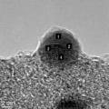
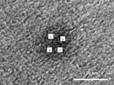
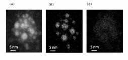
- FIG. 57 shows silver antimony alloy particles
- FIG. 57A shows a STEM-HAADF image
- FIG. 57C shows a STEM mapping result (Sb).
- Dispersion X-ray analyzer Centurio (manufactured by JEOL)
- atomic resolution analysis electron microscope JEM-ARM200F (manufactured by JEOL) Acceleration voltage: 200.0 kV, magnification: 6000000
- silver antimony alloy particles particles that are those in which 2 to 5 nm silver particles exist in one particle, and there is a portion where silver does not exist between the silver particles (EDS: antimony 100%). .
- An object of the present invention is to provide a novel alloy that is a solid metal alloy and can sufficiently exhibit characteristics expected as an alloy, and nanoparticles of the alloy.
- the present invention provides a solid metal alloy in which at least two kinds of metals constituting the alloy exhibit a nano-scale fine mixed state.
- the solid metal alloy of the present invention shows a fine mixed state in which the above two types of metals are in a nano level even in a specific region of a solid phase showing a non-solid solution state in an equilibrium diagram.
- the at least two kinds of metals are unevenly distributed, and differ depending on the kind of the at least two kinds of metals. It is a region including a metal eutectic or a region including the at least two kinds of metal eutectics and intermetallic compounds.
- the region in which the metal composing the alloy is unevenly distributed is defined as ⁇ a component ratio of the metal composing the alloy and a component ratio of the metal composing the alloy within a nano-level microscopic range by microanalysis. This is a region where a difference exceeding 30% occurs. More specifically, in microanalysis with a beam diameter of 5 nm using TEM-EDS analysis or microanalysis with a beam diameter of 0.2 nm using STEM-EDS analysis, the diameter is 5 nm using TEM-EDS analysis.
- the alloy according to the present invention at least two kinds of metals constituting the alloy show a fine mixed state at the nano level.
- the metal alloy of the present invention as a result of performing a micro range analysis with a beam diameter of 5 nm using TEM-EDS analysis, at least all of the above-mentioned two types of metals are found at all analysis points. It is to be detected. Further, in the metal alloy of the present invention, as a result of performing a micro range analysis with a beam diameter of 0.2 nm using STEM-EDS analysis, at least two kinds of metals are detected at all analysis points. It is what is done.
- the metal alloy of the present invention is a result of performing a micro range analysis with a beam diameter of 5 nm using a TEM-EDS analysis, or a micro alloy with a beam diameter of 0.2 nm using a STEM-EDS analysis.
- the at least two kinds of metals are both detected at all analysis points.
- the above two kinds of metals constituting the alloy exhibit a finely mixed state at the nano level, so that the characteristics expected as an alloy are sufficiently exhibited. It can be done.
- the alloy of the present invention for example, a silver-copper alloy, a silver-copper tin alloy, a silver-nickel alloy, and a gold-nickel alloy
- the alloy mainly has a non-eutectic structure containing no eutectic of the at least two kinds of metals. It is thought that.
- the alloy is considered to be mainly composed of a non-eutectic structure containing no eutectic of at least two kinds of metals and an intermetallic compound.
- the solid metal alloy according to the present invention is mainly composed of a substitutional solid solution of two kinds of metals without constituting the metal alloy.
- solid solutions are broadly classified into interstitial solid solutions and substitutional solid solutions, but the alloys obtained according to the present invention are recognized as substitutional solid solutions.
- the difference between the substitutional solid solution and the interstitial solid solution can be observed by TEM or STEM observation, XRD measurement, thermal analysis, etc., but observation by TEM or STEM is particularly effective.
- a substitutional solid solution is a solid solution in which a metal element at a lattice point in a spatial lattice is replaced with another element.
- the substitutional solid solution can be clearly observed by TEM or STEM observation of the alloy, and the influence of the distortion of the crystal lattice due to the replacement of the metal element at the lattice point by other elements, Is observed with a swell.
- the interstitial solid solution is observed in a state different from the substitutional solid solution alloy by observing the alloy with TEM or STEM because other elements enter the gaps of the crystal lattice.
- the alloy according to the present invention is an alloy composed of a combination of at least two kinds of metal elements on the periodic table, and includes a specific region that does not form a solid solution in the equilibrium diagram of the alloy.
- a typical example that does not show such a specific region is an all solid solution type alloy.
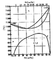
- it is a Ni—Cu alloy, and its equilibrium diagram is shown in FIG.
- This type of all-solid-solution type alloy forms a uniform solid solution in the entire region with respect to the molar ratio (ratio) of the alloy, and there is no specific region of the solid phase showing a non-solid solution state.
- FIGS. 4B to 5D An example including a specific region is shown in FIGS. 4B to 5D.
- the specific region of the solid phase in which the at least two kinds of metals are unevenly distributed is indicated by dots.
- FIG. 4B is an Au—Si alloy equilibrium diagram and is called a eutectic reaction type. An alloy exhibiting this kind of alloy equilibrium state is completely dissolved in a liquid state, but does not dissolve at all in a solid state. Therefore, since the solid solution is not formed in the entire region with respect to the molar ratio (ratio) of the alloy, the solid region of all molar ratios is the specific region.
- ratio molar ratio
- FIG. 4 (C1) is an Au—Ni alloy equilibrium diagram
- FIG. 4 (C2) is an Au—Pt alloy equilibrium diagram
- FIG. 4 (C3) is a representative diagram of this kind, which is called a eutectic reaction type
- FIG. 4 (C4) is a representative diagram of what is called a peritectic reaction type.
- An alloy showing this kind of alloy equilibrium state is completely dissolved in a liquid state, but partially in a solid state. Therefore, the region described as (a + ⁇ ) in the molar ratio (ratio) of the alloy is a state where the ⁇ phase and the ⁇ phase are separated into two phases, and the ⁇ phase and the ⁇ phase are unevenly distributed at an extremely fine level. It has become.
- FIG. 4 (D) is a Cu-Pb alloy equilibrium diagram, which is called a twin crystal reaction type.
- this type of alloy showing an alloy equilibrium state, a part of the alloy is dissolved in the liquid state, and a part of the alloy is not dissolved in the solid state or a part of the alloy is in solution. Therefore, in the region where both of the two types of metals contained in the alloy are in a solid state, the specific region is the same as in the above-described FIGS. 4B, 4C1, 2C3, and 3C3.
- Fig. 4 (E1) is an Fe-Bi alloy equilibrium diagram
- Fig. 4 (E2) is an Al-Tl alloy equilibrium diagram.
- An alloy showing this type of alloy equilibrium is completely soluble in the liquid state. They do not fit or are slightly soluble, and do not dissolve at all in the solid state. Therefore, in the region where both of the two types of metals contained in the alloy are in a solid state, the specific region is the same as in the above-described FIGS. 4B, 4C1, 2C3, and 3C3.
- FIG. 4 (F) is an Ag—Sr alloy equilibrium diagram, where an intermetallic compound or an intermediate phase is generated in an alloy showing this type of alloy equilibrium.
- the region where the intermetallic compound or intermediate phase is generated is the specific region.
- FIGS. 5A to 5D are shown. These figures are representative diagrams in the case where they are completely solid-solved on the high temperature side from the lattice transformation point, but are partially solid-solved or not at all on the low-temperature side.
- 5A and 5B perform the same change as the above eutectic reaction in a solid state, and are called a eutectoid type.
- the one shown in FIG. 5C is called a percolation type because the same reaction as the peritectic reaction occurs in a solid state.
- FIG. 5C is called a percolation type because the same reaction as the peritectic reaction occurs in a solid state.
- 5D is an example in the case where only one component metal in the alloy has an allotropic transformation point, and the solid solubility limit decreases discontinuously due to the existence of the allotropic transformation point. It is a representative figure.
- FIG 5 (A) Figure 5 phase diagram (D), (A + ⁇ ), ( ⁇ + B), (A + B), ( ⁇ + ⁇ ), ( ⁇ + ⁇ ), ( ⁇ + ⁇ ), ( ⁇ + ⁇ ), ( ⁇ + ⁇ ), ( ⁇ + ⁇ ), ( The region described as ⁇ + ⁇ ) is in a state separated into at least two phases and is not mixed at an extremely fine level, and a solid region having a molar ratio becomes the specific region.
- the metal alloy of the present invention may be produced by any method. For example, at least two treatment surfaces that are disposed opposite to each other and that can be approached / separated and at least one rotates relative to the other are arranged. It can be produced by mixing and precipitating at least two kinds of metal ions and a reducing agent in a thin film fluid formed therebetween. Specifically, it can be manufactured by using the apparatus shown in Patent Document 5.
- the inventor of the present invention is obtained by mixing and precipitating a fluid containing at least two kinds of metal ions and a fluid containing a reducing agent.
- the agent is not particularly limited, but hydrazine monohydrate or sodium borohydride can be exemplified.
- a dispersing agent exhibiting reducing properties such as polyvinylpyrrolidone and octylamine.
- the reduction reaction of at least two kinds of metals could be controlled at the atomic level, the kind of processing fluid, the pH, the molar ratio of metal ions, the rotational speed of the processing surface, etc.
- the inventors of the present invention consider that by setting conditions, an alloy of at least two kinds of metals can realize a uniform mixed state on an atomic scale.
- the fluid containing the above reducing agent may contain one kind of reducing agent, or may contain at least two kinds of reducing agents (or substances showing reducibility), By including at least two kinds of reducing agents, it becomes easy to control the deposition time of at least two kinds of metals constituting the alloy and to deposit at least two kinds of metals constituting the alloy substantially simultaneously. It can be deposited as an alloy showing a finely mixed state.
- the fluid containing the above reducing agent may contain one kind of reducing agent, or may contain at least two kinds of reducing agents (or substances showing reducibility).
- the metal alloy can be manufactured as particles composed of particles having a particle size of 500 nm or less, desirably particles having a particle size of 100 nm or less, and more desirably solid particles having a particle size of 50 nm or less. Even in such fine particles, the metal alloy particles according to the present invention are those in which at least two kinds of metals constituting the alloy exhibit a fine mixed state at the nano level. The obtained characteristics can be fully exhibited.
- a novel solid metal alloy capable of sufficiently exhibiting the properties expected as an alloy and nano particles of the alloy can be provided.
- silver-copper alloys it is expected that the characteristics of copper, such as the ability to oxidize easily and the suppression of silver migration, will be noticeable.
- a solid solution silver-copper alloy could be provided, and the development of properties such as suppression of the property of copper that is easily oxidized and suppression of silver migration is expected.
- silver-nickel alloy according to the present invention since the silver and nickel silver nickel alloy is mixed substantially higher arcing erosion and to exert resistance, heat resistance and abrasion resistance and welding resistance
- the properties expected as a silver-nickel alloy, such as properties, catalyst performance, and life as a spark plug, are sufficiently exhibited.
- Solid gold nickel alloy according to the present invention since the gold and nickel gold nickel alloy is mixed substantially, and to exert the performance as reliable electrical contact material, heat resistance and abrasion resistance The characteristics expected as a gold-nickel alloy, such as catalyst performance, are sufficiently exhibited.
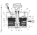
- FIG. 1 is a schematic cross-sectional view of a fluid processing apparatus according to an embodiment of the present invention.
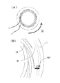
- A is a schematic plan view of a first processing surface of the fluid processing apparatus shown in FIG. 1, and
- B) is an enlarged view of a main part of the processing surface of the apparatus.
- A) is sectional drawing of the 2nd introducing
- B) is the principal part enlarged view of the processing surface for demonstrating the 2nd introducing
- Each is an alloy equilibrium diagram
- (A) is a Ni-Cu alloy equilibrium diagram
- (B) is an Au-Si alloy equilibrium diagram
- (C1) is an Au-Ni alloy equilibrium diagram
- (C2 ) Is an Au-Pt alloy equilibrium diagram
- (C3) is a typical diagram of an eutectic alloy equilibrium diagram
- (C4) is a typical diagram of a peritectic alloy equilibrium diagram
- (D) is Cu-Pb.
- E1 is an Fe—Bi alloy balance diagram
- (E2) is an Al—Tl alloy balance diagram
- (F) is an Ag—Sr alloy balance diagram.
- alloy equilibrium diagrams All are alloy equilibrium diagrams, (A) and (B) are representative diagrams of the equilibrium diagram of the eutectoid alloy, (C) is a representative diagram of the equilibrium diagram of the eutectoid alloy, and (D) is the alloy diagram. It is an example of an equilibrium diagram when there is an allotropic transformation point in only one component metal. Both are alloy equilibrium diagrams.
- Example A STEM-HAADF image
- B EDS mapping result (Ag)
- C EDS mapping result (Cu) of the silver-copper alloy particles produced in Example A8.
- It is a general Ag-Cu alloy equilibrium diagram. It is a STEM-EDS analysis point (four points) in the silver copper alloy particle of the silver copper alloy particle of the silver copper alloy particle produced in Example A8 and the HRTEM image.
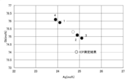
- FIG. 12 shows STEM-EDS analysis results and ICP analysis results of the silver-copper alloy particles produced in Example A8, measured at each STEM-EDS analysis point shown in FIG. It is a TEM image of the silver-copper alloy particle produced in Example A10. It is a TEM image of the silver-copper alloy particle produced in Example A6.
- FIG. 16 shows TEM-EDS analysis results and ICP analysis results of the silver-copper alloy particles produced in Example A10, measured at each TEM-EDS analysis point shown in FIG.
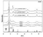
- XRD measurement results obtained using the dry powder of silver-copper alloy particles prepared in Examples A2, A4, and A10, and heat-treated powder obtained by heat-treating the dry powder of the silver-copper alloy particles at 300 ° C. for 30 minutes. It is the XRD measurement result performed using. It is a TEM image of the silver-copper alloy particle produced in Example A7.
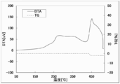
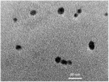
- FIG. 1 It is a TEM image of the silver-copper alloy particle produced in Example A3. It is a TEM image in the low magnification of the silver copper alloy particle produced in Example A4. Changes to Cu ratio of lattice constants in Example A2, A4, and the lattice constant of the prepared silver-copper alloy particles in A10, the lattice constant of the AgCu solid solution obtained from Vegard law, and AgCu solid solution produced by rapid solidification FIG. It is a TEM image of the silver-copper alloy particle after the heat processing which heat-processed the dry powder of the silver-copper alloy particle produced in Example A10 at 300 degreeC for 30 minutes. It is a TG-DTA measurement result in the nitrogen atmosphere of the silver copper alloy particle produced in Example A2.
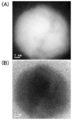
- 26A and 26B are (A) a STEM-HAADF image and (B) a STEM-BF (bright field) image that have been subjected to a radial difference filter process in the same field of view as each image in FIGS. B) Both magnifications are 20 million times). It is an XRD measurement result performed using the dry powder of the silver copper alloy particle produced in Example A13. It is a TEM image of the tin silver copper alloy particle produced in Example A16. It is a general Ag-Ni alloy equilibrium diagram. It is a TEM image of the silver nickel alloy particle produced in Example B1. It is a STEM image of the silver nickel alloy particle produced in Example B2, and a STEM-EDS analysis point (four points) in the silver nickel alloy particle of the STEM image.
- FIG. 4 shows TEM images of silver-nickel alloy particles produced in Example B3 and TEM-EDS analysis points (four points) in silver-nickel alloy fine particles of the TEM images.
- FIG. 33 shows EDS analysis results and ICP analysis results of the silver-nickel alloy particles produced in Example B2 measured at each STEM-EDS analysis point shown in FIG. It is an EDS analysis result and an ICP analysis result which measured the silver nickel alloy particle produced in Example B3 at each TEM-EDS analysis point shown in FIG. It is a TEM image in the low magnification of the silver nickel alloy particle produced in Example B1. It is an XRD measurement result performed using the dry powder of the silver nickel alloy particle produced in Example B2.
- FIG. 3 is a general Au—Ni alloy equilibrium diagram.
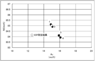
- FIG. 48 shows EDS analysis results and ICP analysis results of the silver antimony alloy particles produced in Example D2 measured at each STEM-EDS analysis point shown in FIG. 47.
- FIG. FIG. 48 shows EDS analysis results and ICP analysis results of the silver antimony alloy particles produced in Example D2 measured at each STEM-EDS analysis point shown in FIG. 47.
- FIG. FIG. 48 shows EDS analysis results and ICP analysis results of the silver antimony alloy particles produced in Example D2 measured at each STEM-EDS analysis point shown in FIG. 47.
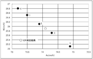
- FIG. 49 shows EDS analysis results and ICP analysis results of the silver antimony alloy particles produced in Example D3, measured at each TEM-EDS analysis point shown in FIG. 48.
- FIG. It is a TEM image in the low magnification of the silver antimony alloy particle produced in Example D1.
- Silver antimony alloy particles prepared in Example D3, (A) STEM-HAADF image, (B) is a STEM-BF (bright field) image ((A) (B) both ratio is 12 million times).
- the type of the alloy is not particularly limited.
- the two types of metals show a nano-level fine mixed state in a specific region of the solid phase where the at least two types of metals are unevenly distributed. Is.
- Type of alloy Specifically, silver copper alloy, silver copper tin alloy, silver nickel alloy, gold nickel alloy, silver antimony alloy can be exemplified. These alloys are mainly composed of an eutectic of at least two kinds of metals constituting the alloy, contain intermetallic compounds, or are non-uniform solid solutions even if they are solid solutions of two kinds of metals. The specific region of the solid phase in which the at least two kinds of metals are unevenly distributed is shown in the alloy equilibrium diagram.
- the state of the alloy changes depending on the temperature, but the above-mentioned at least two kinds of metals are unevenly distributed under a specific temperature condition of a solid at a specific component ratio.
- the metal constituting the alloy is in a finely mixed state at the nano level. Is shown.
- a method for producing the alloy of the present invention is not limited, but one fluid obtained by dissolving or molecularly dispersing at least two kinds of metals constituting the alloy in a solvent and the other fluid containing a reducing agent are mixed to obtain alloy particles.
- a method of precipitation can be exemplified. Although it does not specifically limit as said reducing agent, All the reducing agents which can reduce
- reducing agent examples include hydrazines (hydrazine, hydrazine monohydrate, phenylhydrazine, hydrazinium sulfate, etc.), amines (dimethylaminoethanol, triethylamine, octylamine, dimethylaminoborane, etc.
- Organic acids citric acid, ascorbic acid, tartaric acid, malic acid, malonic acid or salts thereof, formic acid, formaldehyde, etc.
- Alcohols methanol, ethanol, isopropyl alcohol, ethylene glycol, diethylene glycol, triethylene glycol, tetraethylene) Glycol, benzotriazole, etc.
- hydrides sodium borohydride, lithium borohydride, lithium triethylborohydride, etc.
- the use of at least two reducing agents selected from these reducing agents is advantageous in that the two types of metal ions constituting the alloy are reduced almost simultaneously. It is.
- alcohols methanol, ethanol, isopropyl alcohol, ethylene glycol, diethylene glycol, triethylene glycol, tetraethylene glycol, benzotriazole, etc.
- alcohols can also be used as a solvent and used in combination with other reducing agents. be able to.
- pyrrolidones polyvinyl pyrrolidone, 1-vinyl pyrrolidone, N-vinyl pyrrolidone, methyl pyrrolidone
- amines especially octylamine
- the reducing agent and a reducing substance that performs other functions may be used in combination so that the ions of the two types of metal constituting the alloy can be reduced substantially simultaneously.
- the substance that also acts as a solvent or a dispersant can be blended not only in a fluid containing a reducing agent but also in a fluid containing metal ions.
- the present invention provides (A) a solid silver copper alloy, (B) a solid silver nickel alloy, (C) a solid gold nickel alloy, (D) a solid silver antimony alloy, or a metal other than the metal constituting these alloys.
- the solid-state metal alloy is not limited to a solid metal alloy composed of at least three kinds of metals. However, in order to enhance a more specific understanding, each of (A) to (D) in order The alloy will be described.
- the silver-copper alloy according to the present invention is a silver-copper alloy (AgCu alloy) that does not substantially contain a eutectic.
- AgCu alloy silver-copper alloy
- silver and copper form a eutectic in this region (region where the concentration of copper contained in the silver-copper alloy is 0.1 wt% to 99.94 wt%).
- It is a silver-copper alloy mainly composed of a non-eutectic structure containing no crystal.
- the concentration of copper contained in the silver-copper alloy is 0.1 wt% to 99.94 wt%, preferably 0.5 wt% to 99.50 wt%, more preferably 1.0 wt%.
- the solid silver-copper alloy is a solid silver-copper alloy mainly composed of a non-eutectic structure containing no eutectic at room temperature. Thus, it is presumed that silver migration, particularly ion migration generated by ionization of silver can be suppressed.
- the silver-copper alloy according to the present invention is a silver-copper alloy mainly composed of a non-eutectic structure containing no eutectic.
- a silver-copper alloy mainly composed of a non-eutectic structure refers to the present invention. 65% by volume, more preferably 80% by volume or more of the silver-copper alloy is a silver-copper alloy having a non-eutectic structure.
- examples of the non-eutectic structure in the present invention include solid solutions and amorphous.
- the present inventors observed the silver-copper alloy according to the present invention with various apparatuses at room temperature, and the silver-copper alloy according to the present invention mainly has a non-eutectic structure containing no eutectic.
- the solid silver-copper alloy As described above, the present inventors observed the silver-copper alloy according to the present invention with various apparatuses at room temperature, and the silver-copper alloy according to the present invention mainly has a non-eutectic structure containing no eutectic.
- the solid silver-copper alloy is mainly has a non-eutectic structure containing no eutectic.
- the silver-copper alloy particles at room temperature are placed in an environment of microscopic analysis (TEM-EDS analysis or STEM-EDS analysis) used in the examples described later, and irradiated with an electron beam with an acceleration voltage of 200 kV.
- the silver-copper alloy mainly composed of a non-eutectic structure containing no eutectic was confirmed.
- temperature control of the sample itself irradiated with the electron beam is not performed.
- the silver-copper alloy particles subjected to these observations were subjected to DSC measurement in Examples (A2, A4, A10) to be described later, and their state was not changed in a temperature range of room temperature to 180 ° C. I have confirmed.
- the analysis method for the presence of the eutectic in the silver-copper alloy is not particularly limited, but microscopic analysis is preferable, and the distribution state of silver and copper, and the weight ratio or molar ratio of silver and copper can be analyzed, particularly for a minute region. Analytical techniques are preferred.
- TEM-EDS energy dispersive X-ray spectroscopic analysis
- SEM-EDS energy dispersive X-ray spectroscopic analysis
- HRTEM high resolution TEM
- HAADF-STEM Elemental mapping using high angle scattering annular dark field scanning transmission microscopy
- STEM scanning transmission electron microscope
- STEM-EDS energy dispersive X-ray spectroscopic analysis under scanning transmission electron microscope
- EELS Electron energy loss spectroscopy
- STEM-HAADF images As a silver-copper alloy mainly composed of a non-eutectic structure containing no eutectic in the present invention, STEM-HAADF images (FIGS. 7A, 8A, and 9) shown in FIGS. (A)), and EDS mapping results for them (FIGS. 7B, 8C, 8B, 9C, 9B, and 9C). And (C) is a mapping result of Cu.
- the copper concentration is 9.1 wt%.
- grains shown in FIG. 8, in the ICP analysis result of the silver copper alloy particle powder, it is Ag: Cu 69.9: 30.1 (molar ratio), in other words, a silver copper alloy The concentration of copper contained in is 20.2 wt%.
- the copper concentration is 3.0 wt%.
- the above-mentioned silver-copper alloys are all in the Ag-Cu alloy equilibrium diagram, which is the ratio of silver and copper in the solid phase ⁇ + ⁇ region. As seen in the respective EDS mapping results, the silver and copper are No apparent segregation is observed in one particle, and no silver-only region or copper-only region, silver-only particle, or copper-only particle is not confirmed.
- the silver-copper alloy according to the present invention was found to have silver and copper at 50% or more of the analysis points. Is detected within ⁇ 30%, preferably within 20%, more preferably within 10% of the molar ratio of silver and copper obtained from the ICP analysis result.
- FIG. 16 shows the TEM-EDS analysis results measured at each analysis point shown in FIG. From the analysis results shown in FIG. 16, the molar ratio of silver and copper in the TEM-EDS analysis is within ⁇ 30% of the molar ratio of silver and copper obtained by the ICP analysis results when the analysis point is 50% or more. Has been detected and meets this.
- silver-copper alloy particles contain eutectic, many analysis points where Ag is 100% or Cu is 100%, or the ratio of silver and copper in ⁇ phase or ⁇ phase should be detected. It is. That is, it turns out that said silver-copper alloy particle
- grains are silver-copper alloys which do not contain a eutectic.
- the silver-copper alloy according to the present invention was found to have a silver content of 50% or more of the analysis points. It is desirable that the molar ratio of copper and copper be detected within ⁇ 30% of the molar ratio of silver and copper obtained by ICP analysis results.
- the beam with a diameter of 0.2 nm is close to the atomic radius of silver and copper.
- the information from the depth direction and the periphery is captured, it is substantially larger than the atomic size of silver or copper. It is possible to capture area information.
- Analysis points (4 points) and FIG. 12 show STEM-EDS analysis results analyzed at each analysis point shown in FIG. From the analysis results shown in FIG. 12, the molar ratio of silver and copper in the STEM-EDS analysis is within ⁇ 30% of the molar ratio of silver and copper obtained by the ICP analysis results when the analysis point is 50% or more. Has been detected and meets this. If the silver-copper alloy particles contain eutectic, many analysis points where Ag is 100% or Cu is 100%, and the ratio of silver and copper in ⁇ and ⁇ phases should be detected. It is. That is, it turns out that said silver-copper alloy particle
- grains are silver-copper alloys which do not contain a eutectic.
- the concentration of copper contained in the silver-copper alloy is 36.8 wt%) shown in FIG. The atomic arrangement) is observed in one direction, and it can be seen that the silver-copper alloy particles shown in FIG. 13 have no crystal grain boundaries.
- the beam diameter in the case of using the EDS analysis varies depending on the capability of the apparatus to be used, but is preferably, for example, 25 nm, more preferably 10 nm, still more preferably 5 nm. It is preferable that Depending on the analyzer, 0.5 nm is more preferable, and 0.2 nm is more preferable.
- the beam diameter was 5 nm in the case of TEM-EDS analysis and the beam diameter was 0.2 nm in the case of STEM-EDS analysis.
- TEM or STEM observation conditions are preferably 250,000 times or more, more preferably 500,000 times or more.
- the determination of the analysis location is not particularly limited regardless of whether it is singular or plural. However, it is preferable to perform analysis on a plurality of locations, and when the target of analysis is particles, EDS analysis is performed on each of the plurality of particles. Or a plurality of locations in a single particle may be analyzed by EDS. For example, when the particle diameter is 5 nm and the EDS beam diameter is 5 nm, a method of performing EDS analysis on a plurality of particles may be used, or the beam irradiation position in EDS analysis is slightly changed. Thus, EDS analysis may be performed on a plurality of locations in a single particle.
- EDS analysis may be performed on a plurality of locations in a single particle.
- the number of EDS analysis locations is not particularly limited, but is preferably 3 or more, more preferably 10 or more, and even more preferably 25 or more.
- the silver-copper alloy according to the present invention as a result of analyzing the molar ratio of silver and copper in the minute range by the above-mentioned beam diameter using TEM-EDS analysis or STEM-EDS analysis, 50% or more of analysis points , Preferably 65% or more, more preferably 80% or more, and the molar ratio of silver and copper is within ⁇ 30% of the molar ratio of silver and copper obtained by ICP analysis results, preferably within 20%, More preferably, it is desirable to detect within 10%.
- An apparatus capable of such analysis is not particularly limited.
- an apparatus capable of energy dispersive X-ray spectroscopy (TEM-EDS) under transmission electron microscope observation an energy dispersive X-ray analyzer JED-2300 (manufactured by JEOL), transmission electron microscope, JEM-2100 (manufactured by JEOL), and energy dispersive X-ray spectroscopic analysis (STEM-EDS) under scanning transmission electron microscope are possible
- TEM-EDS energy dispersive X-ray spectroscopic analysis
- a high-resolution analytical electron microscope equipped with an r-TEM EDS detector (Ametech), a Titan 80-300 (made by FEI) or an energy dispersive X-ray analyzer, Centurio (made by JEOL), An atomic resolution analytical electron microscope, JEM-ARM200F (manufactured by JEOL) and the like can be mentioned.
- the ratio (molar ratio) between silver and copper contained in the silver-copper alloy in the present invention is not particularly limited.
- a silver-copper alloy having a higher silver molar ratio may be used, or a silver-copper alloy having a higher copper molar ratio may be used.
- the alloy which consists of silver and copper is described as a silver copper alloy irrespective of the molar ratio of silver and copper contained in the said silver copper alloy.
- the silver-copper alloy in the present invention is preferably silver-copper alloy particles having a particle diameter of 50 nm or less. More preferred is a silver-copper alloy having a particle diameter of 25 nm or less, and further preferred is a silver-copper alloy particle having a particle diameter of 10 nm or less.
- the reason is that nanometer-sized particles exhibit specific physical properties such as low melting point and low temperature sintering property due to quantum size effect. For example, with the progress of nanotechnology in recent years, conductive pastes for forming electronic circuits using nanoparticles are required as materials that can form circuits on plastic substrates by the process of coating and baking. Can satisfy that requirement.
- the obtained silver-copper alloy including the silver-copper alloy shown in each figure has a particle diameter of 50 nm or less, and there are also silver-copper alloy particles of 25 nm or less and 10 nm or less.
- the silver-copper alloy which concerns on this invention is a silver-copper alloy particle which does not require the heat processing by a dry type.
- the silver-copper alloy of the present invention may contain a small amount of impurities, so that the present invention intentionally or unintentionally contains silver or copper. It is allowed to include other elements.
- a tin element can be exemplified.
- the ratio of these elements is not particularly limited.
- tin: silver: copper 95.0 to 93.0: 5.0 to 3.0: 2.0 to 0
- Examples other than tin are not particularly limited and include all elements. Examples of such elements include gold, palladium, nickel, chromium, manganese, vanadium, iron, and molybdenum.
- the proportion of other metals that are considered to be unintentionally contained as impurities is not particularly limited, but is less than 0.05 wt% of the total silver-copper alloy, more preferably less than 0.02 wt%, and still more preferably 0.01 wt%. %.
- Silver-copper alloy particle production method 1 It does not specifically limit as a manufacturing method of the said silver-copper alloy.
- a method of thermally decomposing silver and copper compounds or a method of reducing silver and copper ions may be used.
- a silver-copper alloy is prepared by mixing a fluid containing silver ions and copper ions with a fluid containing a reducing agent. It is preferable that it is the manufacturing method of the silver copper alloy particle
- grains may be sufficient.
- the fluid containing the above reducing agent may contain one type of reducing agent or may contain at least two types of reducing agent.
- the deposition time of silver and copper can be controlled, and silver and copper can be substantially precipitated at the same time.
- the above reducing agent is used. It does not preclude the use of a fluid containing one kind of reducing agent as a fluid containing.
- a first reducing agent fluid containing at least one reducing agent and a second reducing agent containing at least one reducing agent different from the reducing agent used in the first reducing agent fluid You may use two types of fluids, a fluid.
- the fluid containing silver ions and copper ions, or the fluid containing silver ions and the copper ions is not particularly limited, but includes a solution containing silver ions and copper ions, or a solution containing silver ions and copper ions.
- a solution is preferred.
- the production method include a method of dissolving a silver or copper simple substance in hydrochloric acid, nitric acid, aqua regia, or the like, a method of dissolving a silver or copper compound in a solvent, and the like.
- a fluid containing silver ions and copper ions may be prepared by dissolving silver alone and / or silver compound and copper alone and / or copper compound in a solvent at a time, or silver alone and / or silver compound.
- a fluid containing silver ions and copper ions may be prepared by mixing a silver solution obtained by dissolving copper in a solvent and a copper solution obtained by dissolving copper alone and / or a copper compound in a solvent.
- the silver or copper compound is not particularly limited, and examples thereof include silver or copper salts, oxides, nitrides, carbides, complexes, organic salts, organic complexes, and organic compounds.
- Silver or copper salts are not particularly limited, but nitrates and nitrites, sulfates and sulfites, formates and acetates, phosphates and phosphites, hypophosphites and chlorides, oxy salts And acetylacetonate salt.
- Other compounds include silver or copper alkoxides.
- solvent The two kinds of metals and / or compounds thereof can be mixed, preferably dissolved or molecularly dispersed in a solvent to produce a fluid containing one or both of the two kinds of metal ions.
- the above silver simple substance and / or silver compound and / or copper simple substance and / or copper compound are mixed in a solvent, preferably dissolved or molecularly dispersed to obtain silver ions and copper ions. Or a fluid containing silver ions and a fluid containing copper ions.
- the said silver simple substance and / or a silver compound, and / or a copper simple substance and / or a copper compound can be arbitrarily selected and used according to the objective.
- the solvent for dissolving the silver simple substance and / or the silver compound and / or the copper simple substance and / or the copper compound include water, an organic solvent, and a mixed solvent obtained by mixing them.
- Examples of the water include tap water, ion-exchanged water, pure water, ultrapure water, and RO water
- examples of the organic solvent include alcohol compound solvents, amide compound solvents, ketone compound solvents, ether compound solvents, and aromatic compounds.
- examples include solvents, carbon disulfide, aliphatic compound solvents, nitrile compound solvents, sulfoxide compound solvents, halogen compound solvents, ester compound solvents, ionic liquids, carboxylic acid compounds, and sulfonic acid compounds.
- Each of the above solvents may be used alone or in combination.
- Basic substances In addition, it can be carried out by mixing or dissolving a basic substance or an acidic substance in the solvent.
- basic substances include metal hydroxides such as sodium hydroxide and potassium hydroxide, metal alkoxides such as sodium methoxide and sodium isopropoxide, and amine compounds such as triethylamine, diethylaminoethanol, and diethylamine. .
- acidic substances include inorganic acids such as aqua regia, hydrochloric acid, nitric acid, fuming nitric acid, sulfuric acid and fuming sulfuric acid, and organic acids such as formic acid, acetic acid, chloroacetic acid, dichloroacetic acid, oxalic acid, trifluoroacetic acid and trichloroacetic acid. It is done.
- These basic substances or acidic substances can be carried out by mixing with various solvents as described above, or can be used alone.
- the alcohol compound solvent examples include methanol, ethanol, isopropanol, n-propanol, 1-methoxy-2-propanol, and the like. Further, linear alcohol such as n-butanol, 2- Examples thereof include branched alcohols such as butanol and tert-butanol, polyhydric alcohols such as ethylene glycol and diethylene glycol, and propylene glycol monomethyl ether. Examples of the ketone compound solvent include acetone, methyl ethyl ketone, and cyclohexanone.
- Examples of the ether compound solvent include dimethyl ether, diethyl ether, tetrahydrofuran, and the like.
- Examples of the aromatic compound solvent include benzene, toluene, xylene, nitrobenzene, chlorobenzene, and dichlorobenzene.
- Examples of the aliphatic compound solvent include hexane.
- Examples of the nitrile compound solvent include acetonitrile.
- Examples of the sulfoxide compound solvent include dimethyl sulfoxide, diethyl sulfoxide, hexamethylene sulfoxide, sulfolane and the like.
- halogen compound solvent examples include chloroform, dichloromethane, trichloroethylene, iodoform, and the like.
- ester compound solvent examples include ethyl acetate, butyl acetate, methyl lactate, ethyl lactate, 2- (1-methoxy) propyl acetate and the like.
- the ionic liquids for example, 1-butyl-3-methylimidazolium and PF 6 - and salts with (hexafluorophosphate) and the like.
- Examples of the amide compound solvent include N, N-dimethylformamide, 1-methyl-2-pyrrolidone, 2-pyrrolidinone, 1,3-dimethyl-2-imidazolidinone, ⁇ -caprolactam, formamide, N-methylformamide, Examples include acetamide, N-methylacetamide, N, N-dimethylacetamide, N-methylpropanamide, hexamethylphosphoric triamide and the like.
- Examples of the carboxylic acid compound include 2,2-dichloropropionic acid and squaric acid.
- Examples of the sulfonic acid compound include methanesulfonic acid, p-toluenesulfonic acid, chlorosulfonic acid, trifluoromethanesulfonic acid, and the like.
- silver and copper alloys include hydride reducing agents such as sodium borohydride and lithium borohydride, aldehydes such as formalin and acetaldehyde, sulfites, formic acid, oxalic acid, citric acid, and succinic acid.
- hydride reducing agents such as sodium borohydride and lithium borohydride
- aldehydes such as formalin and acetaldehyde
- sulfites formic acid, oxalic acid, citric acid, and succinic acid.
- Carboxylic acids such as ascorbic acid, or salts thereof, lactones, aliphatic monoalcohols such as ethanol, butanol and octanol, monoalcohols such as alicyclic monoalcohols such as terpineol, ethylene glycol, propylene glycol, Aliphatic diols such as diethylene glycol and dipropylene glycol, polyhydric alcohols such as glycerin and trimethylolpropane, polyethers such as polyethylene glycol and polypropylene glycol, and alcohols such as diethanolamine and monoethanolamine Kanoruamin acids, hydroquinone, resorcinol, sodium aminophenol, glucose or citric acid, hypochlorous acid or a salt thereof, transition metal ions (titanium or iron ions, etc.) or the like hydrazines and amines are exemplified.
- At least one of the above reducing agents is used.
- hydrazines examples include, but are not limited to, hydrazine, hydrazine monohydrate, hydrazine carbonate, hydrazinium sulfate, phenylhydrazine, 1-methyl-1-phenylhydrazine, 1,1-diphenylhydrazine hydrochloride, and the like.
- amines include, but are not limited to, the formula: R a NH 2 ; R a R b NH; or R a R b R c N; [wherein R a , R b and R c are the same or different from each other] R a and R b may be bonded to each other to form a cyclic amino group with an adjacent nitrogen atom. Or a salt thereof and the like.
- triethylamine, triethanolamine, dimethylaminoethanol and the like can be mentioned.
- the reduction rate of silver and copper or the precipitation time of silver and copper can be controlled as described above.
- the mechanism is not particularly limited, but silver and copper having different characteristics, particularly silver and copper having different standard electrode potentials (Cu 2+ + 2e ⁇ ⁇ Cu: +0.337 V, Ag + + e ⁇ ⁇ Ag: +0.799 V)
- silver, which is a precious metal that is more easily reduced is more likely to be reduced and precipitated before copper, and silver and copper are used alone or as an eutectic.
- the silver-copper alloy particles in the present invention are likely to have a non-eutectic structure that does not contain a eutectic, and the silver ion can be obtained by using the fluid processing apparatus described in Patent Document 5, which is an application of the present applicant, which will be described later. And a fluid containing copper ions and a fluid containing a reducing agent are mixed to precipitate silver-copper alloy particles, thereby producing uniform and homogeneous silver-copper alloy particles confirmed in the examples described later. Is possible.
- the fluid containing the above reducing agent contains at least one kind of the above reducing agent, and it is preferable that the above reducing agent is in a liquid state or mixed in a solvent and dissolved or molecularly dispersed.
- the solvent is not particularly limited. The above-mentioned solvent can be used depending on the purpose.
- the fluid containing the above reducing agent can be carried out even in a state of dispersion or slurry.
- a fluid containing at least two kinds of reducing agents may be used as the fluid containing the reducing agent, and the first reducing agent fluid containing at least one kind of reducing agent and the first reducing agent are used.
- the pH of each fluid in the present invention is not particularly limited. It can be appropriately changed depending on the molar ratio, particle diameter, crystallinity, etc. of the two kinds of metals in the intended alloy particles of at least two kinds of metals. Regarding pH adjustment of a fluid containing two kinds of metal ions or a fluid containing one metal ion, a fluid containing the other metal ion, and a fluid containing a reducing agent, the above acidic substance or basic substance is added to each fluid. It is also possible to change depending on the type of metal or compound used, the type of reducing agent, and the concentration.
- the pH after mixing the fluid containing silver ions and copper ions or the fluid containing silver ions, the fluid containing copper ions and the fluid containing a reducing agent is not particularly limited, but may be 7 to 14. It is preferably 8 to 13, more preferably 11 to 13. More specifically, when the pH of the fluid containing silver ions and copper ions or the fluid containing silver ions, the fluid containing copper ions, and the fluid containing a reducing agent is 7 or less, the silver Reduction of ions or copper ions tends to be insufficient, and it becomes difficult to control the reduction rate of silver and copper.
- the pH of the fluid after mixing is higher than 14, a compound containing silver or copper oxygen, for example, a hydroxide or an oxide is likely to be generated.
- the pH of the fluid after mixing is in the range of 11 to 13, the uniformity of silver and copper in the produced silver-copper alloy particles tends to be high. Even within the grains, the uniformity of silver and copper tends to be high, which is preferable.
- it does not specifically limit about the adjustment method of pH of the fluid after mixing. It can be carried out by adjusting the pH of each fluid or changing the flow rate of each fluid so that the pH of the fluid after mixing is in the above pH range.
- the temperature in each fluid in the present invention is not particularly limited. Similar to the pH, it can be appropriately changed depending on the molar ratio, particle diameter, crystallinity, etc. of the two metals in the alloy particles of the target at least two metals.
- dispersants and surfactants can be used according to the purpose and necessity. Although it does not specifically limit, As a surfactant and a dispersing agent, various commercially available products generally used, products, or newly synthesized products can be used. Examples include anionic surfactants, cationic surfactants, nonionic surfactants, dispersants such as various polymers, and the like. These may be used alone or in combination of two or more. Some dispersants exhibit reducibility, and examples thereof include polyvinylpyrrolidone and n-octylamine.
- the surfactant and the dispersing agent include a metal containing a fluid containing two kinds of metal ions, a fluid containing one metal ion and another metal ion, or a fluid containing a reducing agent. It may be contained in any of the fluids used to make the alloy particles or in a plurality of fluids used. In addition, the above surfactant and dispersant may be contained in the third fluid.
- the third fluid is not a fluid containing the above two types of metal ions, is not a fluid containing one metal ion, is not a fluid containing the other metal ion, and is a fluid containing a reducing agent. But say fluid.
- the dispersant or the like includes a fluid containing the above reducing agent in advance, a fluid containing two kinds of metal ions or a fluid containing one metal ion and the other metal ion. It is preferable to introduce into at least one of the fluids contained.
- the silver-nickel alloy according to the present invention is a silver-nickel alloy (AgNi alloy) substantially free of eutectic.
- the eutectic means one having a eutectic structure.
- the ratio (weight ratio and molar ratio) of silver and nickel in the solid phase region in an Ag—Ni alloy equilibrium diagram (for example, a general Ag—Ni alloy equilibrium diagram is shown in FIG. 30 as an example).
- Solid silver nickel alloy Solid silver nickel alloy.
- silver and nickel do not mix in this region (region where the concentration of nickel contained in the silver-nickel alloy is higher than 0 wt%), but in the present invention, the alloy in which both are uniformly mixed also in this region.
- It is a silver-nickel alloy mainly composed of a non-eutectic structure containing no eutectic.
- the silver-nickel alloy according to the present invention is a silver-nickel alloy mainly composed of a non-eutectic structure containing no eutectic.
- the term “silver-nickel alloy mainly composed of a non-eutectic structure” refers to the present invention. 50% by volume or more of the silver-nickel alloy according to the present invention is a silver-nickel alloy having a non-eutectic structure.
- examples of the non-eutectic structure in the present invention include solid solutions and amorphous.
- the analysis method for the presence (amount) of the eutectic in the silver-nickel alloy is not particularly limited. However, as in the case of the silver-copper alloy, the microscopic analysis is preferable. An analytical method capable of analyzing the weight ratio or molar ratio is preferred.
- TEM-EDS energy dispersive X-ray spectroscopic analysis
- SEM-EDS energy dispersive X-ray spectroscopic analysis
- HRTEM high resolution TEM
- HAADF-STEM Elemental mapping using high angle scattering annular dark field scanning transmission microscopy
- STEM scanning transmission electron microscope
- STEM-EDS energy dispersive X-ray spectroscopic analysis under scanning transmission electron microscope
- EELS Electron energy loss spectroscopy
- the concentration of nickel is 35.0 wt%.
- the above-mentioned silver-nickel alloys are all ratios of silver and nickel, which are not mixed in the Ag-Ni alloy equilibrium diagram, but in the examples described later, each of silver and nickel is in one particle. No apparent segregation is observed, and no silver-only region or nickel-only region cannot be confirmed.
- FIG. 33 shows STEM-EDS analysis points (four points) with a beam diameter of 0.2 nm in diameter of the silver-nickel alloy particles
- FIG. 34 shows EDS analyzed at each analysis point shown in FIG. The analysis results are shown.
- the silver-nickel alloy according to the present invention was subjected to a micro-range analysis with a beam diameter of 0.2 nm using STEM-EDS analysis.
- the molar ratio of silver to nickel was ICP at 50% or more of analysis points. It is desirable to detect within ⁇ 30% of the molar ratio of silver and nickel obtained from the analysis results, but from the analysis results shown in FIG. 34, the silver in the STEM-EDS analysis is at 50% or more of the analysis points. The molar ratio of nickel to nickel is detected within ⁇ 30% of the molar ratio of silver to nickel obtained by the ICP analysis result, and this is satisfied. If silver-nickel alloy particles contain a eutectic, a large number of analysis points with 100% Ag or 100% Ni should be detected. That is, it can be seen that the silver-nickel alloy particles are a silver-nickel alloy containing no eutectic. Further, FIG.
- FIG. 33 shows TEM-EDS analysis points (4 points) with a beam diameter of 5 nm in silver nickel alloy particles
- FIG. 35 shows EDS analysis results measured at each analysis point shown in FIG. Indicates.
- the silver-nickel alloy according to the present invention was subjected to a micro-range analysis with a beam diameter of 5 nm using TEM-EDS analysis. Although it is desirable that the detection is performed within ⁇ 30% of the molar ratio of silver and nickel obtained by the above method, from the analysis result shown in FIG. Is detected within ⁇ 30% of the molar ratio of silver and nickel obtained from the ICP analysis result, and this is satisfied.
- the above analysis is preferably performed in a region having a diameter of 50 nm or less.
- the beam diameter in the case of using the EDS analysis varies depending on the capability of the apparatus used, but is preferably, for example, 25 nm, more preferably 10 nm, still more preferably. Is preferably 5 nm. Depending on the analyzer, 0.5 nm is more preferable, and 0.2 nm is more preferable. In the examples of the present invention, the beam diameter was 5 nm in the case of TEM-EDS analysis, and the beam diameter was 0.2 nm in the case of STEM-EDS analysis.
- the determination of the analysis location is not particularly limited, but it is preferable to perform the analysis on a plurality of locations, and when the analysis target is particles, the EDS analysis may be performed on each of the plurality of particles.
- EDS analysis may be performed on a plurality of locations in a single particle. For example, when the particle diameter is 5 nm and the EDS beam diameter is 5 nm, a method of performing EDS analysis on a plurality of particles may be used, or the beam irradiation position in EDS analysis is slightly changed. Thus, EDS analysis may be performed on a plurality of locations in a single particle.
- EDS analysis may be performed on a plurality of locations in a single particle.
- the method of EDS analysis of a plurality of locations in a single particle is more preferable.
- the number of EDS analysis locations is not particularly limited, but is preferably 3 or more, more preferably 10 or more, and still more preferably 25 or more.
- the present invention as a result of performing the above-mentioned micro range analysis with the beam diameter using TEM-EDS analysis or STEM-EDS analysis, 50% or more, preferably 65% or more, more preferably 80% at a plurality of analysis points.
- the molar ratio between silver and nickel is detected within ⁇ 30%, preferably within 20%, more preferably within 10% of the molar ratio between silver and nickel obtained from the ICP analysis result. desirable.
- An apparatus capable of such analysis is not particularly limited.
- an apparatus capable of energy dispersive X-ray spectroscopy (TEM-EDS) under transmission electron microscope observation an energy dispersive X-ray analyzer , A transmission electron microscope equipped with JED-2300 (manufactured by JEOL), JEM-2100 (manufactured by JEOL), a high-resolution analytical electron microscope equipped with an r-TEM EDS detector (manufactured by Ametech), Titan 80-300 (manufactured by JEOL) FEI) and the like.
- TEM-EDS energy dispersive X-ray spectroscopy
- the ratio (molar ratio) of silver and nickel contained in the silver nickel alloy in the present invention is not particularly limited.
- a silver nickel alloy having a higher silver molar ratio may be used, or a silver nickel alloy having a higher nickel molar ratio may be used.
- the alloy which consists of silver and nickel is described as a silver nickel alloy irrespective of the molar ratio of silver and nickel contained in the said silver nickel alloy.
- the silver nickel alloy in the present invention is preferably silver nickel alloy particles having a particle diameter of 50 nm or less. More preferred are silver nickel alloy particles having a particle diameter of 25 nm or less, and further preferred are silver nickel alloy particles having a particle diameter of 10 nm or less.
- the reason is that nanometer-sized particles exhibit specific physical properties such as low melting point and low temperature sintering property due to quantum size effect.
- conductive pastes for forming electronic circuits using nanoparticles are required as materials that can form circuits on plastic substrates by the process of coating and baking. Can satisfy that requirement.
- all of the obtained silver nickel alloys including the silver nickel alloy shown in each figure had a particle diameter of 50 nm or less, and some silver nickel alloy particles of 25 nm or less and 10 nm or less.
- the silver-nickel alloy according to the present invention may contain a small amount of impurities, and the present invention is intentionally or unintentionally included in the silver-nickel alloy. Including elements other than silver or nickel.
- Silver-nickel alloy particle production method 1 It does not specifically limit as a manufacturing method of said silver nickel alloy particle.
- a method of thermally decomposing silver and nickel compounds or a method of reducing silver and nickel ions may be used, but a silver nickel alloy is prepared by mixing a fluid containing silver ions and nickel ions with a fluid containing a reducing agent. It is preferable to be a method for producing silver-nickel alloy particles for precipitating.
- at least one reducing agent is used as the fluid containing the reducing agent.
- Two types of fluids may be used: a first reducing agent fluid containing types and a second reducing agent fluid containing at least one type of reducing agent different from the reducing agent used in the first reducing agent fluid.
- the present invention can also be carried out by mixing a fluid containing silver ions, a fluid containing nickel ions, and a fluid containing a reducing agent.
- the fluid containing silver ions and nickel ions, or the fluid containing silver ions and the fluid containing nickel ions is not particularly limited, but includes a solution containing silver ions and nickel ions, or a solution containing silver ions and nickel ions.
- a solution is preferred.
- the production method include a method of dissolving a single metal of silver or nickel in hydrochloric acid, nitric acid, aqua regia, a method of dissolving a compound of silver or nickel in a solvent, and the like.
- a fluid containing silver ions and nickel ions may be prepared by dissolving silver alone or a silver compound and nickel alone or a nickel compound at once in a solvent, or silver containing a silver simple substance or a silver compound dissolved in a solvent.
- a fluid containing silver ions and nickel ions may be produced by mixing a solution and a nickel solution in which nickel alone or a nickel compound is dissolved in a solvent.
- carbonized_material, a complex, an organic salt, an organic complex, an organic compound etc. are mentioned as an example.
- Silver or nickel salts are not particularly limited, but nitrates and nitrites, sulfates and sulfites, formates and acetates, phosphates and phosphites, hypophosphites and chlorides, oxy salts And acetylacetonate salt.
- Other compounds include silver or nickel alkoxides.
- solvent for mixing preferably dissolving or molecularly dispersing the above two kinds of metals constituting the alloy (in this case, silver and nickel), the above-mentioned explanation of the alloy of silver and copper, more specifically, Solvent) (acidic and basic substances) (detailed explanation of solvent) (fluid containing reducing agent) (pH: fluid of each fluid, fluid after mixing) (temperature) (dispersing agent, etc.) The description is omitted.
- the reducing agent is not particularly limited, and any reducing agent capable of reducing silver and / or nickel ions can be used.
- hydride reducing agents such as sodium borohydride and lithium borohydride, aldehydes such as formalin and acetaldehyde, sulfites, formic acid, oxalic acid, citric acid, succinic acid, carboxylic acids such as ascorbic acid, Or a salt thereof, or a lactone, an aliphatic monoalcohol such as ethanol, butanol or octanol, a monoalcohol such as an alicyclic monoalcohol such as terpineol, a fat such as ethylene glycol, propylene glycol, diethylene glycol or dipropylene glycol Diols, polyhydric alcohols such as glycerin and trimethylolpropane, polyhydric alcohols such as glycerin and trimethylolpropane, polyhydric alcohols such as
- reducing agent hydrazines
- at least one of the above reducing agents is used. Further, when two or more of the above reducing agents are used, there is a possibility that the reduction rate of silver and nickel or the precipitation time of silver and nickel can be controlled.
- reducing agent hydrazines are preferably used. Examples of the hydrazines include, but are not limited to, hydrazine, hydrazine monohydrate, hydrazine carbonate, hydrazinium sulfate, phenylhydrazine, 1-methyl-1-phenylhydrazine, 1,1-diphenylhydrazine hydrochloride, and the like.
- the use of two or more reducing agents may control the reduction rate of silver and nickel or the precipitation time of silver and nickel as described above.
- the mechanism is not particularly limited, but silver and nickel having different characteristics, particularly silver and nickel having different standard electrode potentials (Ni 2+ + 2e ⁇ ⁇ Ni: ⁇ 0.228 V, Ag + + e ⁇ ⁇ Ag: +0.799 V)
- silver, which is a precious metal that is more easily reduced is more likely to be reduced and deposited before nickel, and silver and nickel are singly or non-uniformly. It is thought that it is easy to precipitate as an alloy, but by using two or more kinds of reducing agents, it is possible to accelerate nickel reduction, precipitation, or silver reduction, precipitation, or both. It is thought that can be deposited simultaneously.
- the solid gold-nickel alloy particles according to the present invention are gold-nickel alloy particles having a particle diameter of 500 nm or less, preferably gold-nickel alloy particles of 100 nm or less, and more preferably gold-nickel alloy particles of 50 nm or less.
- the solid gold-nickel alloy particles according to the present invention have a solid gold concentration in which the concentration of nickel contained in the gold-nickel alloy is 2.0 wt% to 92.7 wt%, preferably 3.0 wt% to 90.0 wt%. It is a nanoparticle of a nickel alloy, and is a nanoparticle mainly composed of a solid solution gold-nickel alloy (AuNi alloy) in which two kinds of metals, gold and nickel, show a fine mixed state at a nano level. A general Au—Ni alloy equilibrium diagram is shown in FIG. 38. Generally, conventional alloys have a mixture of ⁇ and ⁇ phases.
- the present invention is a uniform gold-nickel alloy, and is a gold-nickel alloy mainly composed of an alloy in which these two kinds of metals are solid-solutioned so as to show a nano-level fine mixed state. .
- This makes it possible to demonstrate its performance as a highly reliable electrical contact material such as connectors, small relays, and printed wiring boards as electronic components, as well as the characteristics expected of gold-nickel alloys, such as heat resistance, wear resistance, and catalytic performance. It is possible to demonstrate.
- the gold-nickel alloy according to the present invention is a gold-nickel alloy mainly composed of an alloy in which two kinds of metals are solid-solved so as to show a nano-level fine mixed state.
- an amorphous etc. are mentioned as an alloy in which the two types of metals in the present invention were dissolved so as to show a nano-scale fine mixed state.
- Analytical method for the uniformity of gold and nickel in a gold-nickel alloy and whether the gold-nickel alloy is mainly composed of an alloy in which two kinds of metals are in a solid solution so as to show a fine mixed state at a nano level Although there is no particular limitation, microscopic analysis is preferable, and an analysis technique capable of analyzing the distribution state of gold and nickel, and the weight ratio or molar ratio is particularly preferable for a minute region.
- TEM-EDS energy dispersive X-ray spectroscopic analysis
- SEM-EDS energy dispersive X-ray spectroscopic analysis
- HRTEM high resolution TEM
- HAADF-STEM Elemental mapping using high angle scattering annular dark field scanning transmission microscopy
- STEM-EDS scanning transmission electron microscope
- STEM-EDS energy dispersive X-ray spectroscopic analysis under scanning transmission electron microscope
- EELS Electron energy loss spectroscopy
- the gold-nickel alloy has a uniform solution of gold and nickel, and the gold-nickel alloy is an alloy in which two kinds of metals are dissolved so as to show a finely mixed state at the nano level. Microscopic analysis is preferred for proof of whether it is the subject.
- the TEM shown in FIGS. 39, 40, and 41 is used as a gold-nickel alloy mainly composed of a uniform gold-nickel alloy and an alloy in which two kinds of metals are mixed so as to show a fine mixed state at a nano level. Examples thereof include gold-nickel alloy particles such as images and STEM images.
- the concentration of nickel is 22.9 wt%.
- the concentration of nickel contained is 63.0 wt%.
- the concentration of nickel is 9.4 wt%.
- the above-mentioned gold-nickel alloy particles are all in the Au-Ni alloy equilibrium diagram (FIG. 4 (C1)), which is the ratio of gold and nickel in the ⁇ + ⁇ region. It is not confirmed that the particles are clearly segregated, and the gold-only region or the nickel-only region cannot be confirmed.
- FIG. 40 shows STEM-EDS analysis points (4 points) with a beam diameter of 0.2 nm in the diameter of the gold-nickel alloy particles
- FIG. 42 shows EDS analyzed at each analysis point shown in FIG. The analysis results are shown.
- the gold-nickel alloy particles according to the present invention were subjected to a micro-range analysis with a beam diameter of 0.2 nm using STEM-EDS analysis.
- the molar ratio of gold to nickel was 50% or more of the analysis points. It is desirable to detect within ⁇ 30% of the molar ratio of gold and nickel obtained from the ICP analysis result.
- the STEM-EDS analysis at 50% or more of the analysis points. The molar ratio of gold and nickel is detected within ⁇ 30% of the molar ratio of gold and nickel obtained from the ICP analysis result, and this is satisfied.
- the gold-nickel alloy particles are non-uniform, or if the two types of metal contain a portion that is not solid-solued so as to show a nano-scale fine mixed state
- the gold and nickel in the gold-nickel alloy particles A number of analytical points should be detected where the ratio is the ratio of gold and nickel, respectively ⁇ or ⁇ . That is, it can be seen that the gold-nickel alloy particles are a uniform gold-nickel alloy, and a gold-nickel alloy in which two kinds of metals are solid-solved so as to show a nano-scale fine mixed state.
- FIG. 41 shows TEM-EDS analysis points (5 points) with a beam diameter of 5 nm in the gold-nickel alloy particles
- the molar ratio of gold to nickel is ICP analysis at 50% or more of the analysis points.
- the detection is within ⁇ 30%, preferably within 20%, more preferably within 10% of the molar ratio of gold and nickel obtained by the results, the analysis points shown in FIG.
- the molar ratio of gold to nickel in the TEM-EDS analysis is detected within ⁇ 30% of the molar ratio of gold to nickel obtained by the ICP analysis result, and this is satisfied. .
- the “uniform gold-nickel alloy” is a gold-nickel alloy in which the ratio of gold to nickel in the gold-nickel alloy is a predetermined ratio, specifically, in one gold-nickel alloy particle.
- the gold-nickel alloy particles in which the ratio (molar ratio) of gold and nickel obtained by EDS analysis is within ⁇ 30% of the ratio (molar ratio) of gold and nickel obtained by ICP analysis results. Thus, the same result can be obtained for a plurality of gold-nickel alloy particles.
- the “uniform gold-nickel alloy” is a gold-nickel alloy in which gold and nickel are uniformly mixed.
- the concentration of nickel contained is 9.4 wt%.
- the gold-nickel alloy nanoparticles described above are all in the Au—Ni alloy equilibrium state diagram 4 (C1) (FIG. 38), which is the ratio of gold and nickel in the ⁇ + ⁇ region. No apparent segregation is observed in one nanoparticle, and no gold-only region or nickel-only region can be confirmed.
- FIG. 40 shows STEM-EDS analysis points (four points) with a beam diameter of 0.2 nm in the gold-nickel alloy nanoparticles
- FIG. 42 shows analysis at each analysis point shown in FIG. An EDS analysis result is shown.
- the gold-nickel alloy nanoparticles according to the present invention were analyzed in a minute range with a beam diameter of 0.2 nm using STEM-EDS analysis.
- the molar ratio of gold to nickel was 50% or more of the analysis points. 42, it is desirable that the detection is within ⁇ 30%, preferably within 20%, more preferably within 10% of the molar ratio of gold and nickel obtained from the ICP analysis result, but from the analysis result shown in FIG.
- the molar ratio of gold and nickel in the STEM-EDS analysis was detected within ⁇ 30% of the molar ratio of gold and nickel obtained from the ICP analysis results. Satisfies.
- the gold-nickel alloy nanoparticles are non-uniform, or if the two types of metal contain parts that are not solid-solued so as to show a nano-level fine mixed state, the gold and nickel in the gold-nickel alloy nanoparticles A large number of analysis points should be detected in which the ratio of ⁇ and ⁇ is the ratio of gold and nickel, respectively. That is, it can be seen that the gold-nickel alloy nanoparticles are a uniform gold-nickel alloy, and a gold-nickel alloy in which two kinds of metals are solid-solved so as to show a nano-scale fine mixed state. Further, FIG.
- FIG. 41 shows TEM-EDS analysis points (5 points) with a beam diameter of 5 nm in the gold-nickel alloy nanoparticles
- FIG. 43 shows measurement at each analysis point shown in FIG. An EDS analysis result is shown.
- the gold-nickel alloy nanoparticles according to the present invention were analyzed in a minute range with a beam diameter of 5 nm using TEM-EDS analysis.
- the molar ratio of gold to nickel was found to be ICP at 50% or more of the analysis points.
- the “uniform gold-nickel alloy” is a gold-nickel alloy in which the ratio of gold to nickel in the gold-nickel alloy is a predetermined ratio, specifically, one gold-nickel alloy nanoparticle.
- the ratio (molar ratio) of gold and nickel obtained by EDS analysis is within ⁇ 30% of the ratio (molar ratio) of gold and nickel obtained by ICP analysis results
- the same result is obtained for a plurality of gold-nickel alloy nanoparticles.
- the “uniform gold-nickel alloy” is a gold-nickel alloy in which gold and nickel are uniformly mixed.
- the above analysis is preferably performed in a region having a diameter of 50 nm or less.
- the beam diameter in the case of using the EDS analysis varies depending on the capability of the apparatus used, but is preferably, for example, 25 nm, more preferably 10 nm, still more preferably. Is preferably 5 nm. Depending on the analyzer, 0.5 nm is more preferable, and 0.2 nm is more preferable. In the examples of the present invention, the beam diameter was 5 nm in the case of TEM-EDS analysis, and the beam diameter was 0.2 nm in the case of STEM-EDS analysis.
- the determination of the analysis location is not particularly limited, but it is preferable to perform the analysis on a plurality of locations, and when the analysis target is particles, the EDS analysis may be performed on each of the plurality of particles.
- EDS analysis may be performed on a plurality of locations in a single particle. For example, when the particle diameter is 5 nm and the EDS beam diameter is 5 nm, a method of performing EDS analysis on a plurality of particles may be used, or the beam irradiation position in EDS analysis is slightly changed. Thus, EDS analysis may be performed on a plurality of locations in a single particle.
- EDS analysis may be performed on a plurality of locations in a single particle.
- a method of EDS analysis of a plurality of locations in a single particle is more preferable.
- the number of EDS analyzes is not particularly limited, but is preferably 3 or more, more preferably 10 or more, and still more preferably 25 or more.
- the gold-nickel alloy nanoparticles according to the present invention were subjected to the above-described microscopic range analysis using the beam diameter using TEM-EDS analysis or STEM-EDS analysis.
- it is 65% or more, more preferably 80% or more, and the molar ratio of gold to nickel is within ⁇ 30%, preferably within 20% of the molar ratio of gold to nickel obtained by ICP analysis results, more It is desirable to detect within 10%.
- An apparatus capable of such analysis is not particularly limited.
- an apparatus capable of energy dispersive X-ray spectroscopy (TEM-EDS) under transmission electron microscope observation an energy dispersive X-ray analyzer , A transmission electron microscope equipped with JED-2300 (manufactured by JEOL), JEM-2100 (manufactured by JEOL), a high-resolution analytical electron microscope equipped with an r-TEM EDS detector (manufactured by Ametech), Titan 80-300 (manufactured by JEOL) FEI) and the like.
- TEM-EDS energy dispersive X-ray spectroscopy
- the ratio (molar ratio) of gold and nickel contained in the gold-nickel alloy nanoparticles in the present invention is not particularly limited.
- Gold-nickel alloy nanoparticles having a higher gold molar ratio or gold-nickel alloy nanoparticles having a higher nickel molar ratio may be used.
- an alloy containing gold and nickel is described as a gold-nickel alloy regardless of the molar ratio of gold to nickel contained in the gold-nickel alloy nanoparticles, and the gold-nickel alloy nanoparticles are referred to as gold-nickel alloys. It is described as nickel alloy nanoparticles.
- the gold-nickel alloy nanoparticles in the present invention preferably have a particle diameter of 500 nm or less. More preferred are gold-nickel alloy nanoparticles having a particle size of 100 nm or less, and even more preferred are gold-nickel alloy nanoparticles having a particle size of 50 nm or less.
- nanometer-sized particles exhibit specific physical properties such as low melting point and low temperature sintering property due to quantum size effect. For example, with the progress of nanotechnology in recent years, conductive pastes for forming electronic circuits using nanoparticles are required as materials that can form circuits on plastic substrates by the process of coating and baking. Can satisfy that requirement.
- all of the obtained gold-nickel alloys including the gold-nickel alloy shown in each figure had a particle diameter of 500 nm or less, and some gold-nickel alloy nanoparticles of 100 nm or less and 50 nm or less.
- Method for producing gold-nickel alloy nanoparticles 1 It does not specifically limit as a manufacturing method of the gold nickel alloy nanoparticle which concerns on this invention.
- a method of thermally decomposing gold and nickel compounds or a method of reducing gold and nickel ions may be used, but a gold-nickel alloy is prepared by mixing a fluid containing gold ions and nickel ions with a fluid containing reducing agents.
- a method for producing gold-nickel alloy nanoparticles in which nanoparticles are deposited is preferable.
- the manufacturing method of the gold nickel alloy nanoparticle which mixes the fluid containing a gold ion, the fluid containing a nickel ion, and the fluid containing a reducing agent, and depositing a gold nickel alloy nanoparticle may be sufficient.
- the fluid containing the reducing agent includes a first reducing agent fluid containing at least one reducing agent and a second reducing agent fluid containing at least one reducing agent different from the reducing agent used in the first reducing agent fluid. Two types of fluids may be used.
- the fluid containing gold ions and nickel ions, or the fluid containing gold ions and the fluid containing nickel ions is not particularly limited, but includes a solution containing gold ions and nickel ions, or a solution containing gold ions and nickel ions.
- a solution is preferred.
- the production method include a method of dissolving gold or nickel simple metal in hydrochloric acid, nitric acid, aqua regia and the like, a method of dissolving gold or nickel compound in a solvent, and the like.
- a simple substance of gold and / or a gold compound and a simple substance of nickel and / or a nickel compound may be dissolved in a solvent at a time to produce a fluid containing gold ions and / or nickel ions.
- a fluid containing gold ions and nickel ions may be prepared by mixing a gold solution obtained by dissolving a nickel compound in a solvent and a nickel solution obtained by dissolving nickel alone and / or a nickel compound in a solvent.
- the gold or nickel compound is not particularly limited, and examples thereof include gold or nickel salts, oxides, nitrides, carbides, complexes, organic salts, organic complexes, and organic compounds.
- Gold or nickel salts are not particularly limited, but nitrates and nitrites, sulfates and sulfites, formates and acetates, phosphates and phosphites, hypophosphites and chlorides, oxy salts And acetylacetonate salt.
- Other compounds include gold or nickel alkoxides.
- solvent for mixing preferably dissolving or molecularly dispersing the above two types of metals constituting the alloy (in this case, gold and nickel), the above description of the alloy of silver and copper, more specifically, Solvent) (acidic and basic substances) (detailed explanation of solvent) (fluid containing reducing agent) (pH: fluid of each fluid, fluid after mixing) (temperature) (dispersing agent, etc.) The description is omitted.
- the reducing agent is not particularly limited, and any reducing agent capable of reducing gold and / or nickel ions can be used.
- hydride reducing agents such as sodium borohydride and lithium borohydride, aldehydes such as formalin and acetaldehyde, sulfites, formic acid, oxalic acid, citric acid, succinic acid, carboxylic acids such as ascorbic acid, Or a salt thereof, or a lactone, an aliphatic monoalcohol such as ethanol, butanol or octanol, a monoalcohol such as an alicyclic monoalcohol such as terpineol, a fat such as ethylene glycol, propylene glycol, diethylene glycol or dipropylene glycol Diols, polyhydric alcohols such as glycerin and trimethylolpropane, polyhydric alcohols such as glycerin and trimethylolpropane, polyhydric alcohols such as
- reducing agent hydrazines
- at least one of the above reducing agents is used. Further, when two or more of the above reducing agents are used, there is a possibility that the reduction rate of gold and nickel or the deposition time of gold and nickel can be controlled.
- reducing agent hydrazines are preferably used. Examples of hydrazines include, but are not limited to, hydrazine, hydrazine monohydrate, hydrazine carbonate, hydrazinium sulfate, phenylhydrazine, 1-methyl-1-phenylhydrazine, 1,1-diphenylhydrazine hydrochloride, and the like.
- the reduction rate of gold and nickel or the deposition time of gold and nickel can be controlled.
- the mechanism is not particularly limited, but gold and nickel having different characteristics, particularly gold and nickel having different standard electrode potentials (Ni 2+ + 2e ⁇ Ni: ⁇ 0.228E ⁇ / V, Au + + e ⁇ Au: + 1.68E) ⁇ / V or [AuCl 4 ] ⁇ + 3e ⁇ Au + 4Cl ⁇ : 1.002E ⁇ / V or [AuCl 2 ] ⁇ + e ⁇ Au + 2Cl ⁇ : 1.154E ⁇ / V) will be reduced with one reducing agent
- gold which is a precious metal that is more easily reduced, is more likely to be reduced and precipitated before nickel, and gold and nickel are likely to precipitate alone or as a heterogeneous alloy.
- the silver antimony alloy according to the present invention is a silver antimony alloy (AgSb alloy) substantially free of a eutectic and an intermetallic compound.
- the eutectic refers to those having a eutectic structure, and in the present invention, even when an intermetallic compound is included, it may be expressed as including a eutectic.
- a general Ag—Sb alloy equilibrium diagram is shown in FIG. 45 (source of FIG. 45: Non-Patent Document 1). In the Ag—Sb alloy equilibrium diagram, the Sb concentration was 7.2 at.
- % (8.05 wt%) is an ⁇ solid solution phase mainly composed of silver, but in a region where the Sb concentration is 8.05 wt% or more and less than 100 wt%, an intermetallic compound ⁇ or ⁇ or eutectic is obtained. It is an area including In general, silver and antimony are not mixed in this region (region in which the concentration of antimony contained in the silver antimony alloy is 8.05 wt% or more and less than 100 wt%).
- a homogeneously mixed alloy that is, a silver antimony alloy mainly composed of a non-eutectic structure containing no eutectic and intermetallic compound. In other words, the concentration of antimony contained in the silver antimony alloy is two types of metals. It is a silver antimony alloy mainly composed of a silver antimony alloy dissolved so as to show a fine mixed state at a level.
- the solid silver antimony alloy in the present invention is implemented as a solid silver antimony alloy in which the concentration of antimony contained in the silver antimony alloy is 8.05 wt% or more and less than 100 wt%, preferably 9.0 wt% to 95 wt%.
- the solid silver antimony alloy is a silver antimony alloy mainly composed of a non-eutectic structure containing no eutectic and intermetallic compounds at room temperature.
- the silver antimony alloy according to the present invention is a silver antimony alloy mainly composed of a non-eutectic structure containing no eutectic and intermetallic compounds.
- the term “silver antimony alloy mainly composed of a non-eutectic structure” is a silver antimony alloy having a non-eutectic structure.
- examples of the non-eutectic structure in the present invention include solid solutions and amorphous.
- the present inventors found that the silver antimony alloy according to the present invention does not contain a eutectic and an intermetallic compound.
- the solid silver antimony alloy is mainly composed of a eutectic structure.
- the silver antimony alloy particles at room temperature are placed in the environment of microscopic analysis (TEM-EDS analysis or STEM-EDS analysis) used in the examples described later, and irradiated with an electron beam having an acceleration voltage of 200 kV.
- the silver antimony alloy mainly composed of a non-eutectic structure containing no eutectic was confirmed. At that time, temperature control of the sample itself irradiated with the electron beam is not performed.
- the analysis method relating to the presence of the eutectic or intermetallic compound in the silver antimony alloy there is no particular limitation on the analysis method relating to the presence of the eutectic or intermetallic compound in the silver antimony alloy.
- an analysis method relating to the presence of the eutectic in the silver antimony alloy microscopic analysis is preferable, and an analysis method capable of analyzing the distribution state, weight ratio, or molar ratio of silver and antimony is particularly preferable for a minute region.
- TEM-EDS energy dispersive X-ray spectroscopic analysis
- SEM-EDS energy dispersive X-ray spectroscopic analysis
- HRTEM high-resolution TEM
- HAADF-STEM Elemental mapping using high angle scattering annular dark field scanning transmission microscopy
- STEM-EDS scanning transmission electron microscope
- STEM-EDS energy dispersive X-ray spectroscopic analysis under scanning transmission electron microscope
- EELS Electron energy loss spectroscopy
- the analysis method for the presence of intermetallic compounds in the silver antimony alloy includes XRD measurement in addition to thermal analysis such as differential thermal and thermogravimetric simultaneous measurement (TG-DTA) and differential scanning calorimetry (DSC). .
- XRD measurement is preferable because qualitative and quantitative analysis such as identification of a crystal phase of a crystal substance and evaluation of the ratio of amorphous to crystal are possible.
- the silver antimony alloy is mainly composed of a non-eutectic structure containing no eutectic and intermetallic compounds
- microanalysis and XRD measurement are performed. It is preferable to use in combination.
- a silver antimony alloy mainly comprising a non-eutectic structure containing no eutectic and intermetallic compound in the present invention a TEM image and a STEM image shown in FIGS. 46 to 48, a STEM-HAADF image shown in FIG. Examples thereof include silver antimony alloy particles such as EDS mapping results (FIGS. 52B, 52C, and 52B are Ag mapping results, and FIG. 52C is Sb mapping results).
- the analysis for obtaining the molar ratio of silver to antimony in the silver antimony powder is not particularly limited. And ICP analysis). ICP analysis is preferable because the molar ratio of silver to antimony can be quantitatively analyzed with high accuracy.
- the concentration of antimony is 52.0 wt%.
- the concentration of antimony contained is 77.5 wt%.
- FIG. 47 shows STEM-EDS analysis points (4 points) with a beam diameter of 0.2 nm in the silver antimony alloy particles
- FIG. 49 shows analysis at each analysis point shown in FIG. An EDS analysis result is shown.
- the silver antimony alloy according to the present invention was subjected to a micro-range analysis with a beam diameter of 0.2 nm using STEM-EDS analysis.
- the molar ratio of silver to antimony was 50% or more of the analysis point. It is desirable to detect within ⁇ 30%, preferably within 20%, more preferably within 10% of the molar ratio of silver and antimony obtained by analysis, but from the analysis results shown in FIG.
- the molar ratio of silver and antimony obtained by STEM-EDS analysis was detected within ⁇ 30% of the molar ratio of silver and antimony obtained by ICP analysis. Yes.
- the beam with a diameter of 0.2 nm is close to the atomic radius of silver and antimony, but in actual observation, it captures information from the depth direction and the periphery, so it is substantially larger than the atomic size of silver and antimony. It is possible to capture area information. If the silver antimony alloy particles contain a eutectic, a large number of analysis points where Ag is 100% or Sb is 100%, or the ratio of silver and antimony in the ⁇ solid solution phase should be detected. . That is, it can be seen that the silver antimony alloy particles are a silver antimony alloy containing no eutectic.
- FIG. 48 shows TEM-EDS analysis points (4 points) with a beam diameter of 5 nm in silver antimony alloy particles
- FIG. 50 shows EDS analysis results measured at each analysis point shown in FIG. Show.
- the silver antimony alloy according to the present invention was subjected to a micro-range analysis with a beam diameter of 5 nm using TEM-EDS analysis.
- the molar ratio of silver to antimony was determined by ICP analysis at 50% or more of the analysis points.
- the detection is within ⁇ 30% of the molar ratio of silver and antimony obtained
- the silver obtained by TEM-EDS analysis at 50% or more of the analysis points from the analysis results shown in FIG.
- the molar ratio of antimony is detected within ⁇ 30% of the molar ratio of silver and antimony obtained by ICP analysis, and this is satisfied. If the silver antimony alloy particles contain a eutectic, a large number of analysis points where Ag is 100% or Sb is 100%, or the ratio of silver and antimony in the ⁇ solid solution phase should be detected. . That is, it can be seen that the silver antimony alloy particles are a silver antimony alloy containing no eutectic.
- the above analysis is preferably performed in a region having a diameter of 50 nm or less.
- the beam diameter used for the EDS analysis varies depending on the capability of the apparatus used, but is preferably, for example, 25 nm, more preferably 10 nm, and even more preferably 5 nm. It is preferable that Depending on the analyzer, 0.5 nm is more preferable, and 0.2 nm is more preferable.
- the beam diameter was 5 nm in the case of TEM-EDS analysis and the beam diameter was 0.2 nm in the case of STEM-EDS analysis.
- TEM or STEM observation conditions are preferably 250,000 times or more, more preferably 500,000 times or more.
- the determination of the analysis location is not particularly limited regardless of whether it is singular or plural. However, it is preferable to perform analysis on a plurality of locations, and when the target of analysis is particles, EDS analysis is performed on each of the plurality of particles. Or a plurality of locations in a single particle may be analyzed by EDS. For example, when the particle diameter is 5 nm and the EDS beam diameter is 5 nm, a method of performing EDS analysis on a plurality of particles may be used, or the beam irradiation position in EDS analysis is slightly changed. Thus, EDS analysis may be performed on a plurality of locations in a single particle.
- EDS analysis may be performed on a plurality of locations in a single particle.
- the number of EDS analysis points is not particularly limited, but is preferably 3 or more, more preferably 10 or more, and still more preferably 25 or more.
- the silver antimony alloy according to the present invention as a result of analyzing the molar ratio of silver to antimony in the micro-range analysis by the above-mentioned beam diameter using TEM-EDS analysis or STEM-EDS analysis, 50% of analysis points were obtained. Or more, preferably 65% or more, more preferably 80% or more, and the molar ratio of silver to antimony is within ⁇ 30% of the molar ratio of silver to antimony obtained by ICP analysis results, preferably within 20% More preferably, it is desirable to detect within 10%.
- the molar ratio of silver and antimony obtained by ICP analysis is Since the molar ratio between silver and antimony in the micro-range analysis results obtained by TEM-EDS analysis or STEM-EDS analysis is greatly different, there is a possibility that a uniform silver antimony alloy cannot be produced.
- An apparatus capable of such analysis is not particularly limited.
- an apparatus capable of energy dispersive X-ray spectroscopy (TEM-EDS) under transmission electron microscope observation an energy dispersive X-ray analyzer JED-2300 (manufactured by JEOL), transmission electron microscope, JEM-2100 (manufactured by JEOL), and energy dispersive X-ray spectroscopic analysis (STEM-EDS) under scanning transmission electron microscope are possible
- a high-resolution analytical electron microscope equipped with an r-TEM EDS detector (made by Ametech), a Titan 80-300 (made by FEI), or an energy dispersive X-ray analyzer, Centrio (made by JEOL) was equipped.
- atomic resolution analytical electron microscope, JEM-ARM200F manufactured by JEOL
- the ratio (molar ratio) between silver and antimony contained in the silver antimony alloy in the present invention is not particularly limited.
- a silver antimony alloy having a higher silver molar ratio or a silver antimony alloy having a higher antimony molar ratio may be used.
- an alloy composed of silver and antimony is described as a silver antimony alloy regardless of the molar ratio of silver and antimony contained in the silver antimony alloy.
- the silver antimony alloy in the present invention is preferably silver antimony alloy particles having a particle diameter of 50 nm or less. More preferred are silver antimony alloy particles having a particle size of 25 nm or less, and further preferred are silver antimony alloy particles having a particle size of 10 nm or less.
- nanometer-sized particles exhibit specific physical properties such as low melting point and low temperature sintering property due to quantum size effect. For example, with the progress of nanotechnology in recent years, conductive pastes for forming electronic circuits using nanoparticles are required as materials that can form circuits on plastic substrates by the process of coating and baking. Can satisfy that requirement.
- the silver antimony alloy particles obtained include silver antimony alloy particles having a particle size of 50 nm or less, and silver antimony alloy particles having a particle size of 25 nm or less, There were also silver antimony alloy particles having a particle size of 10 nm or less.
- silver antimony alloy particles of 50 nm or more are not excluded.
- a coating film of a uniform silver antimony alloy can be formed by applying the solid silver antimony alloy particles onto a substrate including the plastic substrate and solidifying the solid silver antimony alloy particles. Further, a uniform solid can be formed by accumulating and solidifying the silver antimony alloy particles.
- the silver antimony alloy of the present invention may contain a small amount of impurities. Therefore, the present invention includes silver or antimony intentionally or unintentionally in the silver antimony alloy. It is allowed to include other elements.
- the elements to be intentionally included are not particularly limited and include all elements. Examples of such elements include gold, palladium, nickel, chromium, manganese, vanadium, iron, molybdenum, tin, and cobalt.
- the proportion of other metals that are considered to be unintentionally included as impurities is not particularly limited, but is less than 0.05 wt% of the total silver antimony alloy, more preferably less than 0.02 wt%, still more preferably 0.01 wt%. %.
- the method for producing the silver antimony alloy is not particularly limited.
- a method of thermally decomposing silver and antimony compounds or a method of reducing silver and antimony ions may be used.
- a silver antimony alloy is prepared by mixing a fluid containing silver ions and antimony ions with a fluid containing a reducing agent. It is preferable that the production method deposits the particles.
- grains of a silver antimony alloy may be sufficient.
- the fluid containing the reducing agent includes a first reducing agent fluid containing at least one reducing agent and a second reducing agent fluid containing at least one reducing agent different from the reducing agent used in the first reducing agent fluid. Two types of fluids may be used.
- the fluid containing silver ions and antimony ions, or the fluid containing silver ions and the fluid containing antimony ions is not particularly limited, but includes a solution containing silver ions and antimony ions, or a solution containing silver ions and antimony ions.
- a solution is preferred.
- the production method include a method in which a single metal of silver or antimony is dissolved in hydrochloric acid, nitric acid, or aqua regia, a method in which a compound of silver or antimony is dissolved in a solvent, or the like.
- a fluid containing silver ions and antimony ions may be prepared by dissolving silver alone and / or silver compound and antimony alone and / or antimony compound at a time in a solvent, or silver alone and / or silver compound.
- a fluid containing silver ions and antimony ions may be prepared by mixing a silver solution in which is dissolved in a solvent and an antimony solution in which antimony alone and / or an antimony compound is dissolved in a solvent.
- the silver or antimony compound is not particularly limited, and examples thereof include silver or antimony salts, oxides, nitrides, carbides, complexes, organic salts, organic complexes, and organic compounds.
- Silver or antimony salts are not particularly limited, but nitrates and nitrites, sulfates and sulfites, formates and acetates, phosphates and phosphites, hypophosphites and chlorides, oxy salts And acetylacetonate salt.
- Other compounds include silver or antimony alkoxides.
- the solvent for mixing preferably dissolving or molecularly dispersing the above two metals constituting the alloy (in this case, silver and antimony), the above-described explanation of the alloy of silver and copper, more specifically, Solvent) (acidic and basic substances) (detailed explanation of solvent) (fluid containing reducing agent) (pH: fluid of each fluid, fluid after mixing) (temperature) (dispersing agent, etc.) The description is omitted.
- the reducing agent is not particularly limited, and any reducing agent capable of reducing silver and / or antimony ions can be used.
- hydride-based reducing agents such as sodium borohydride and lithium borohydride, aldehydes such as formaldehyde and acetaldehyde, sulfites, formic acid, oxalic acid, citric acid, succinic acid, ascorbic acid and other carboxylic acids or Its salts or aliphatic monoalcohols such as lactones, ethanol, butanol and octanol, monoalcohols such as alicyclic monoalcohols such as terpineol, aliphatics such as ethylene glycol, propylene glycol, diethylene glycol and dipropylene glycol Diols, polyhydric alcohols such as glycerin and trimethylolpropan
- At least one of the above reducing agents is used.
- the reduction rate of silver and antimony or the precipitation time of silver and antimony can be controlled.
- the mechanism is not particularly limited, but silver and antimony having different characteristics, particularly silver and antimony having different standard electrode potentials (Sb 3+ + 3e ⁇ ⁇ Sb: +0.21 V, Ag + + e ⁇ ⁇ Ag: +0.799 V) are used.
- silver, which is a precious metal that is more easily reduced is more likely to be reduced and precipitated before antimony, and silver and antimony are singly or non-uniformly.
- silver and antimony can be precipitated simultaneously by reducing the antimony, precipitating the silver or delaying the silver reduction, precipitating, or both. Applicant believes that this is possible.
- two or more kinds of the reducing agents it is preferable that at least one of them is a hydride reducing agent.
- the fluid containing the two types of metal ions and the fluid containing the reducing agent are disposed to face each other so as to be able to approach and separate from each other, and at least one of them is rotated with respect to the other. It is preferable to mix in a thin film fluid formed between the surfaces to precipitate the target alloy particles, and use the fluid processing apparatus described in Patent Document 5, which is an application of the present applicant, It is preferable to deposit alloy particles.
- the fluid processing apparatus shown in FIGS. 1 to 3 is the same as the apparatus described in Patent Document 5, and is provided between processing surfaces in a processing unit in which at least one of approaching and separating can rotate relative to the other.
- a first fluid that is a first fluid to be treated among the fluids to be treated is introduced between the processing surfaces, and a flow path into which the first fluid is introduced.
- the second fluid which is the second fluid to be treated among the fluids to be treated, is introduced between the processing surfaces from another flow path having an opening communicating between the processing surfaces. It is an apparatus that performs processing by mixing and stirring the first fluid and the second fluid between the surfaces.
- U indicates the upper side
- S indicates the lower side.
- the upper, lower, front, rear, left and right only indicate a relative positional relationship, and do not specify an absolute position.
- R indicates the direction of rotation.
- C indicates the centrifugal force direction (radial direction).
- This apparatus uses at least two kinds of fluids as a fluid to be treated, and at least one kind of fluid includes at least one kind of an object to be treated and is opposed to each other so as to be able to approach and separate.
- a processing surface at least one of which rotates with respect to the other, and the above-mentioned fluids are merged between these processing surfaces to form a thin film fluid.
- An apparatus for processing an object to be processed As described above, this apparatus can process a plurality of fluids to be processed, but can also process a single fluid to be processed.
- This fluid processing apparatus includes first and second processing units 10 and 20 that face each other, and at least one of the processing units rotates.
- the opposing surfaces of both processing parts 10 and 20 are processing surfaces.
- the first processing unit 10 includes a first processing surface 1
- the second processing unit 20 includes a second processing surface 2.
- Both the processing surfaces 1 and 2 are connected to the flow path of the fluid to be processed and constitute a part of the flow path of the fluid to be processed.
- the distance between the processing surfaces 1 and 2 can be changed as appropriate, but is usually adjusted to 1 mm or less, for example, a minute distance of about 0.1 ⁇ m to 50 ⁇ m.
- the fluid to be processed that passes between the processing surfaces 1 and 2 becomes a forced thin film fluid forced by the processing surfaces 1 and 2.
- the apparatus When a plurality of fluids to be processed are processed using this apparatus, the apparatus is connected to the flow path of the first fluid to be processed and forms a part of the flow path of the first fluid to be processed. At the same time, a part of the flow path of the second fluid to be treated is formed separately from the first fluid to be treated. And this apparatus performs processing of fluid, such as making both flow paths merge and mixing both the to-be-processed fluids between the processing surfaces 1 and 2, and making it react.
- “treatment” is not limited to a form in which the object to be treated reacts, but also includes a form in which only mixing and dispersion are performed without any reaction.
- the first holder 11 that holds the first processing portion 10 the second holder 21 that holds the second processing portion 20, a contact pressure applying mechanism, a rotation drive mechanism, A first introduction part d1, a second introduction part d2, and a fluid pressure imparting mechanism p are provided.
- the first processing portion 10 is an annular body, more specifically a ring-shaped disk.
- the second processing unit 20 is also a ring-shaped disk.
- the materials of the first and second processing parts 10 and 20 are metal, carbon, ceramic, sintered metal, wear-resistant steel, sapphire, and other metals that have undergone hardening treatment, Those with coating, plating, etc. can be used.
- at least a part of the first and second processing surfaces 1 and 2 facing each other is mirror-polished in the processing units 10 and 20.
- the surface roughness of this mirror polishing is not particularly limited, but is preferably Ra 0.01 to 1.0 ⁇ m, more preferably Ra 0.03 to 0.3 ⁇ m.
- At least one of the holders can be rotated relative to the other holder by a rotational drive mechanism (not shown) such as an electric motor.
- Reference numeral 50 in FIG. 1 denotes a rotation shaft of the rotation drive mechanism.
- the first holder 11 attached to the rotation shaft 50 rotates and is used for the first processing supported by the first holder 11.
- the unit 10 rotates with respect to the second processing unit 20.
- the second processing unit 20 may be rotated, or both may be rotated.
- the first and second holders 11 and 21 are fixed, and the first and second processing parts 10 and 20 are rotated with respect to the first and second holders 11 and 21. May be.
- At least one of the first processing unit 10 and the second processing unit 20 can be approached / separated from at least either one, and both processing surfaces 1 and 2 can be approached / separated. .
- the second processing unit 20 approaches and separates from the first processing unit 10, and the second processing unit 20 is disposed in the storage unit 41 provided in the second holder 21. It is housed in a hauntable manner.
- the first processing unit 10 may approach or separate from the second processing unit 20, and both the processing units 10 and 20 may approach or separate from each other. It may be a thing.
- the accommodating portion 41 is a concave portion that mainly accommodates a portion of the second processing portion 20 on the side opposite to the processing surface 2 side, and is a groove that has a circular shape, that is, is formed in an annular shape in plan view. .
- the accommodating portion 41 accommodates the second processing portion 20 with a sufficient clearance that allows the second processing portion 20 to rotate.
- the second processing unit 20 may be arranged so that only the parallel movement is possible in the axial direction, but by increasing the clearance, the second processing unit 20 is
- the center line of the processing part 20 may be tilted and displaced so as to break the relationship parallel to the axial direction of the storage part 41. Furthermore, the center line of the second processing part 20 and the storage part 41 may be displaced.
- the center line may be displaced so as to deviate in the radial direction. As described above, it is desirable to hold the second processing unit 20 by the floating mechanism that holds the three-dimensionally displaceably.
- the above-described fluid to be treated is subjected to both treatment surfaces from the first introduction part d1 and the second introduction part d2 in a state where pressure is applied by a fluid pressure application mechanism p configured by various pumps, potential energy, and the like. It is introduced between 1 and 2.
- the first introduction part d1 is a passage provided in the center of the annular second holder 21, and one end of the first introduction part d1 is formed on both processing surfaces from the inside of the annular processing parts 10, 20. It is introduced between 1 and 2.
- the second introduction part d2 supplies the second processing fluid to be reacted with the first processing fluid to the processing surfaces 1 and 2.
- the second introduction part d ⁇ b> 2 is a passage provided inside the second processing part 20, and one end thereof opens at the second processing surface 2.
- the first fluid to be processed that has been pressurized by the fluid pressure imparting mechanism p is introduced from the first introduction part d1 into the space inside the processing parts 10 and 20, and the first processing surface 1 and the second processing surface 2 are supplied. It passes between the processing surfaces 2 and tries to pass outside the processing portions 10 and 20. Between these processing surfaces 1 and 2, the second fluid to be treated pressurized by the fluid pressure applying mechanism p is supplied from the second introduction part d 2, merged with the first fluid to be treated, and mixed.
- the above-mentioned contact surface pressure applying mechanism applies a force that acts in a direction in which the first processing surface 1 and the second processing surface 2 approach each other to the processing portion.
- the contact pressure applying mechanism is provided in the second holder 21 and biases the second processing portion 20 toward the first processing portion 10.
- the contact surface pressure applying mechanism is a force that pushes in a direction in which the first processing surface 1 of the first processing unit 10 and the second processing surface 2 of the second processing unit 20 approach (hereinafter referred to as contact pressure). It is a mechanism for generating.
- a thin film fluid having a minute film thickness of nm to ⁇ m is generated by the balance between the contact pressure and the force for separating the processing surfaces 1 and 2 such as fluid pressure. In other words, the distance between the processing surfaces 1 and 2 is kept at a predetermined minute distance by the balance of the forces.
- the contact surface pressure applying mechanism is arranged between the accommodating portion 41 and the second processing portion 20.
- a spring 43 that biases the second processing portion 20 in a direction approaching the first processing portion 10 and a biasing fluid introduction portion 44 that introduces a biasing fluid such as air or oil.
- the contact surface pressure is applied by the spring 43 and the fluid pressure of the biasing fluid. Any one of the spring 43 and the fluid pressure of the urging fluid may be applied, and other force such as magnetic force or gravity may be used.
- the second processing unit 20 causes the first treatment by the separation force generated by the pressure or viscosity of the fluid to be treated which is pressurized by the fluid pressure imparting mechanism p against the bias of the contact surface pressure imparting mechanism.
- the first processing surface 1 and the second processing surface 2 are set with an accuracy of ⁇ m by the balance between the contact surface pressure and the separation force, and a minute amount between the processing surfaces 1 and 2 is set. An interval is set.
- the separation force includes the fluid pressure and viscosity of the fluid to be processed, the centrifugal force due to the rotation of the processing part, the negative pressure when the urging fluid introduction part 44 is negatively applied, and the spring 43 is pulled.
- the force of the spring when it is used as a spring can be mentioned.
- This contact surface pressure imparting mechanism may be provided not in the second processing unit 20 but in the first processing unit 10 or in both.
- the second processing unit 20 has the second processing surface 2 and the inside of the second processing surface 2 (that is, the first processing surface 1 and the second processing surface 2).
- a separation adjusting surface 23 is provided adjacent to the second processing surface 2 and located on the entrance side of the fluid to be processed between the processing surface 2 and the processing surface 2.
- the separation adjusting surface 23 is implemented as an inclined surface, but may be a horizontal surface.
- the pressure of the fluid to be processed acts on the separation adjusting surface 23 to generate a force in a direction in which the second processing unit 20 is separated from the first processing unit 10. Accordingly, the pressure receiving surfaces for generating the separation force are the second processing surface 2 and the separation adjusting surface 23.
- the proximity adjustment surface 24 is formed on the second processing portion 20.
- the proximity adjustment surface 24 is a surface opposite to the separation adjustment surface 23 in the axial direction (upper surface in FIG. 1), and the pressure of the fluid to be processed acts on the second processing portion 20. A force is generated in a direction that causes the first processing unit 10 to approach the first processing unit 10.
- the pressure of the fluid to be processed that acts on the second processing surface 2 and the separation adjusting surface 23, that is, the fluid pressure, is understood as a force constituting an opening force in the mechanical seal.
- the projected area A1 of the proximity adjustment surface 24 projected on a virtual plane orthogonal to the approaching / separating direction of the processing surfaces 1 and 2, that is, the protruding and protruding direction (axial direction in FIG. 1) of the second processing unit 20 The area ratio A1 / A2 of the total area A2 of the projected areas of the second processing surface 2 and the separation adjusting surface 23 of the second processing unit 20 projected onto the virtual plane is called a balance ratio K. This is important for the adjustment of the opening force.
- the opening force can be adjusted by the pressure of the fluid to be processed, that is, the fluid pressure, by changing the balance line, that is, the area A1 of the adjustment surface 24 for proximity.
- P1 represents the pressure of the fluid to be treated, that is, the fluid pressure
- K represents the balance ratio
- k represents the opening force coefficient
- Ps represents the spring and back pressure
- the proximity adjustment surface 24 may be implemented with a larger area than the separation adjustment surface 23.
- the fluid to be processed becomes a thin film fluid forced by the two processing surfaces 1 and 2 holding the minute gaps, and tends to move to the outside of the annular processing surfaces 1 and 2.
- the mixed fluid to be processed does not move linearly from the inside to the outside of the two processing surfaces 1 and 2, but instead has an annular radius.
- a combined vector of the movement vector in the direction and the movement vector in the circumferential direction acts on the fluid to be processed and moves in a substantially spiral shape from the inside to the outside.
- the rotating shaft 50 is not limited to a vertically arranged shaft, and may be arranged in the horizontal direction, or may be arranged in an inclined manner. This is because the fluid to be processed is processed at a fine interval between the processing surfaces 1 and 2 and the influence of gravity can be substantially eliminated. Further, this contact surface pressure applying mechanism also functions as a buffer mechanism for fine vibration and rotational alignment when used in combination with a floating mechanism that holds the second processing portion 20 in a displaceable manner.
- At least one of the first and second processing parts 10 and 20 may be cooled or heated to adjust the temperature.
- the first and second processing parts 10 and 10 are adjusted.
- 20 are provided with temperature control mechanisms (temperature control mechanisms) J1, J2.
- the temperature of the introduced fluid to be treated may be adjusted by cooling or heating. These temperatures can also be used for the deposition of the treated material, and also to generate Benard convection or Marangoni convection in the fluid to be treated between the first and second processing surfaces 1 and 2. May be set.
- a groove-like recess 13 extending from the center side of the first processing portion 10 to the outside, that is, in the radial direction is formed on the first processing surface 1 of the first processing portion 10. May be implemented.
- the planar shape of the recess 13 is curved or spirally extending on the first processing surface 1, or is not shown, but extends straight outward, L It may be bent or curved into a letter shape or the like, continuous, intermittent, or branched.
- the recess 13 can be implemented as one formed on the second processing surface 2, and can also be implemented as one formed on both the first and second processing surfaces 1, 2.
- the base end of the recess 13 reaches the inner periphery of the first processing unit 10.
- the tip of the recess 13 extends toward the outer peripheral surface of the first processing surface 1, and the depth (cross-sectional area) gradually decreases from the base end toward the tip.
- a flat surface 16 without the recess 13 is provided between the tip of the recess 13 and the outer peripheral surface of the first processing surface 1.
- the opening d20 is desirably provided on the downstream side (outside in this example) from the concave portion 13 of the first processing surface 1.
- it is installed at a position facing the flat surface 16 on the outer diameter side from the point where the flow direction when introduced by the micropump effect is converted into a laminar flow direction in a spiral shape formed between the processing surfaces. It is desirable to do.
- the distance n in the radial direction from the outermost position of the recess 13 provided in the first processing surface 1 is preferably about 0.5 mm or more.
- the shape of the opening d20 may be a circular shape as shown by a solid line in FIG. 2B or FIG. 3B, or a process that is a ring-shaped disc as shown by a dotted line in FIG. A concentric ring shape surrounding the central opening of the working surface 2 may be used.
- the opening d20 When the annular opening d20 is provided concentrically around the central opening of the processing surface 2, the second fluid introduced between the processing surfaces 1 and 2 is introduced over a wide range in the circumferential direction under the same conditions. Therefore, more uniform fluid processing such as diffusion, reaction, and precipitation can be performed.
- the opening d20 has an annular shape. Further, the ring-shaped opening d20 may not be provided in a concentric circle surrounding the central opening of the processing surface 2. Furthermore, when the opening has an annular shape, the annular opening may be continuous or discontinuous.
- the second introduction part d2 can have directionality.
- the introduction direction from the opening d20 of the second processing surface 2 is inclined with respect to the second processing surface 2 at a predetermined elevation angle ( ⁇ 1).
- the elevation angle ( ⁇ 1) is set to be more than 0 degrees and less than 90 degrees, and in the case of a reaction with a higher reaction rate, it is preferably set at 1 to 45 degrees.
- the introduction direction from the opening d ⁇ b> 20 of the second processing surface 2 has directionality in the plane along the second processing surface 2.
- the introduction direction of the second fluid is a component in the radial direction of the processing surface that is an outward direction away from the center and a component with respect to the rotation direction of the fluid between the rotating processing surfaces. Is forward.
- a line segment in the radial direction passing through the opening d20 and extending outward is defined as a reference line g and has a predetermined angle ( ⁇ 2) from the reference line g to the rotation direction R. This angle ( ⁇ 2) is also preferably set to more than 0 degree and less than 90 degrees.
- This angle ( ⁇ 2) can be changed and implemented in accordance with various conditions such as the type of fluid, reaction speed, viscosity, and rotational speed of the processing surface.
- the second introduction part d2 may not have any directionality.
- the number of fluids to be treated and the number of flow paths are two, but may be one, or may be three or more.
- the second fluid is introduced between the processing surfaces 1 and 2 from the second introduction part d2, but this introduction part may be provided in the first processing part 10 or provided in both. Good. Moreover, you may prepare several introduction parts with respect to one type of to-be-processed fluid.
- the shape, size, and number of the opening for introduction provided in each processing portion are not particularly limited, and can be appropriately changed. Further, an opening for introduction may be provided immediately before or between the first and second processing surfaces 1 and 2 or further upstream.
- the second fluid is introduced from the first introduction part d1 and the first fluid is introduced from the second introduction part d2 contrary to the above. May be introduced.
- the expressions “first” and “second” in each fluid have only an implication for identification that they are the nth of a plurality of fluids, and a third or higher fluid may exist.
- processes such as precipitation / precipitation or crystallization are disposed so as to face each other so as to be able to approach / separate, and at least one of the processing surfaces 1 rotates relative to the other. Occurs with forcible uniform mixing between the two.
- the particle size and monodispersity of the processed material to be processed are the rotational speed and flow velocity of the processing parts 10 and 20, the distance between the processing surfaces 1 and 2, the raw material concentration of the processed fluid, or the processed fluid. It can be controlled by appropriately adjusting the solvent species and the like.
- a fluid containing silver ions and copper ions as a first fluid is disposed so as to be able to approach and separate from the first introduction part d1 which is one flow path, and at least one of them is rotated with respect to the other. It introduce
- a fluid containing a reducing agent as a second fluid is directly introduced into the first fluid film formed between the processing surfaces 1 and 2 from the second introduction part d2 which is a separate flow path.
- the first fluid and the second fluid are disposed between the processing surfaces 1 and 2 whose distance is fixed by the pressure balance between the supply pressure of the fluid to be processed and the pressure applied between the rotating processing surfaces.
- the silver copper alloy particles can be precipitated.
- the second fluid is introduced from the first introduction part d1 and the first fluid is introduced from the second introduction part d2, contrary to the above. May be introduced.
- the expressions “first” and “second” in each fluid have only an implication for identification that they are the nth of a plurality of fluids, and a third or higher fluid may exist.
- silver migration silver is ionized and moves through the solid while repeating the reversible reaction to react with the hydroxyl (OH ⁇ ) ions contained in water to form silver hydroxide, and precipitates and segregates as silver.
- OH ⁇ hydroxyl
- silver-copper alloy particles that can suppress migration more than ever It is also an advantage that can be manufactured.
- TEM electron microscope
- a third introduction part can be provided in the processing apparatus.
- silver is used as the first fluid.
- a fluid containing ions, a fluid containing copper ions as the second fluid, and a fluid containing a reducing agent as the third fluid can be separately introduced into the processing apparatus. If it does so, the density
- a third introduction part and a fourth introduction part can be provided in the processing apparatus.
- a fluid containing silver ions as the fluid, a fluid containing copper ions as the second fluid, a first reducing agent fluid containing at least one reducing agent as the third fluid, and a reducing agent used as the first reducing agent fluid as the fourth fluid It is possible to introduce the second reducing agent fluid containing at least one reducing agent different from the above into the processing apparatus separately. Note that the combination of fluids to be processed (first fluid to fourth fluid) to be introduced into each introduction portion can be arbitrarily set. The same applies to the case where the fifth or more introduction portions are provided, and the fluid to be introduced into the processing apparatus can be subdivided in this way.
- the fluid containing silver ions and the fluid containing copper ions are merged before joining the fluid containing the reducing agent, and the first time before joining the fluid containing silver ions and copper ions. It is desirable that the first reducing agent fluid and the second reducing agent fluid merge.
- the temperature of the fluid to be processed such as the first and second fluids is controlled, and the temperature difference between the first fluid and the second fluid (that is, the temperature difference between the supplied fluids to be processed) is controlled. You can also.
- the temperature of each processed fluid processing device, more specifically, the temperature immediately before being introduced between the processing surfaces 1 and 2 is measured. It is also possible to add a mechanism for heating or cooling each fluid to be processed introduced between the processing surfaces 1 and 2.
- a fluid containing at least silver ions and nickel ions as a first fluid is disposed opposite to each other so as to be able to approach and separate from the first introduction part d1 which is one flow path, and at least one of the fluids is in contact with the other. It introduce
- a fluid containing a reducing agent as a second fluid is directly introduced into the first fluid film formed between the processing surfaces 1 and 2 from the second introduction part d2 which is a separate flow path.
- the first fluid and the second fluid are disposed between the processing surfaces 1 and 2 whose distance is fixed by the pressure balance between the supply pressure of the fluid to be processed and the pressure applied between the rotating processing surfaces. And the silver nickel alloy particles can be precipitated.
- the second fluid is introduced from the first introduction part d1 and the first fluid is introduced from the second introduction part d2, contrary to the above. May be introduced.
- the expressions “first” and “second” in each fluid have only an implication for identification that they are the nth of a plurality of fluids, and a third or higher fluid may exist.
- silver migration silver is ionized, and the silver ions react with hydroxyl (OH-) ions contained in water to form silver hydroxide, repeating the reversible reaction, moving through the solid to precipitate and segregate as silver.
- OH- hydroxyl
- a third introduction part can be provided in the processing apparatus.
- silver is used as the first fluid.
- a fluid containing ions, a fluid containing nickel ions as the second fluid, and a fluid containing a reducing agent as the third fluid can be separately introduced into the processing apparatus. If it does so, the density
- a third introduction part can be provided in the processing apparatus.
- a reducing agent is supplied as the first fluid.
- a first reducing agent fluid containing at least one kind, a second reducing agent fluid containing at least one kind of reducing agent different from the reducing agent used in the first reducing agent fluid as the second fluid, and silver ions and nickel ions as the third fluid It is possible to introduce the fluids containing each separately into the processing apparatus. Note that the combination of fluids to be processed (first fluid to third fluid) to be introduced into each introduction portion can be arbitrarily set. The same applies to the case where the fourth or more introduction portions are provided, and the fluid to be introduced into the processing apparatus can be subdivided in this way.
- the fluid containing silver ions and the fluid containing nickel ions are merged before joining the fluid containing the reducing agent, and the first time before joining the fluid containing silver ions and nickel ions. It is desirable that the first reducing agent fluid and the second reducing agent fluid are merged.
- the temperature of the fluid to be processed such as the first and second fluids is controlled, and the temperature difference between the first fluid and the second fluid (that is, the temperature difference between the supplied fluids to be processed) is controlled. You can also.
- the temperature of each processed fluid processing device, more specifically, the temperature immediately before being introduced between the processing surfaces 1 and 2 is measured. It is also possible to add a mechanism for heating or cooling each fluid to be processed introduced between the processing surfaces 1 and 2.
- a fluid containing at least gold ions and nickel ions as a first fluid is disposed opposite to each other so as to be able to approach and separate from the first introduction part d1 which is one flow path, and at least one of them is relative to the other. It introduce
- a fluid containing a reducing agent as a second fluid is directly introduced into the first fluid film formed between the processing surfaces 1 and 2 from the second introduction part d2 which is a separate flow path.
- the first fluid and the second fluid are disposed between the processing surfaces 1 and 2 whose distance is fixed by the pressure balance between the supply pressure of the fluid to be processed and the pressure applied between the rotating processing surfaces. And gold and nickel alloy nanoparticles can be precipitated.
- the second fluid is introduced from the first introduction part d1 and the first fluid is introduced from the second introduction part d2, contrary to the above. May be introduced.
- the expressions “first” and “second” in each fluid have only an implication for identification that they are the nth of a plurality of fluids, and a third or higher fluid may exist.
- a third introduction part can be provided in the processing apparatus.
- a fluid containing ions, a fluid containing nickel ions as the second fluid, and a fluid containing a reducing agent as the third fluid can be separately introduced into the processing apparatus. If it does so, the density
- a third introduction part can be provided in the processing apparatus.
- each introduction part gold ions and A fluid containing nickel ions; a first fluid containing at least one reducing agent as the second fluid; and a second fluid containing at least one reducing agent different from the reducing agent used in the first reducing agent fluid as the third fluid.
- the reducing agent fluid separately into the processing apparatus.
- the combination of fluids to be processed (first fluid to third fluid) to be introduced into each introduction portion can be arbitrarily set. The same applies to the case where the fourth or more introduction portions are provided, and the fluid to be introduced into the processing apparatus can be subdivided in this way.
- the fluid containing gold ions and the fluid containing nickel ions are joined before joining the fluid containing the reducing agent in the thin film fluid. It is desirable that the first reducing agent fluid and the second reducing agent fluid have joined before joining the containing fluid.
- the temperature of the fluid to be processed such as the first and second fluids is controlled, and the temperature difference between the first fluid and the second fluid (that is, the temperature difference between the supplied fluids to be processed) is controlled. You can also.
- the temperature of each processed fluid processing device, more specifically, the temperature immediately before being introduced between the processing surfaces 1 and 2 is measured. It is also possible to add a mechanism for heating or cooling each fluid to be processed introduced between the processing surfaces 1 and 2.
- a fluid containing at least silver ions and antimony ions as a first fluid is disposed so as to be able to approach and separate from the first introduction part d1 which is one flow path, and at least one of the fluids is opposed to the other. It introduce
- a fluid containing a reducing agent as a second fluid is directly introduced into the first fluid film formed between the processing surfaces 1 and 2 from the second introduction part d2 which is a separate flow path.
- the first fluid and the second fluid are disposed between the processing surfaces 1 and 2 whose distance is fixed by the pressure balance between the supply pressure of the fluid to be processed and the pressure applied between the rotating processing surfaces.
- the silver antimony alloy particles can be precipitated.
- the second fluid is introduced from the first introduction part d1 and the first fluid is introduced from the second introduction part d2, contrary to the above. May be introduced.
- the expressions “first” and “second” in each fluid have only an implication for identification that they are the nth of a plurality of fluids, and a third or higher fluid may exist.
- the first fluid is adjusted so that the concentration of antimony contained in the silver antimony alloy particles is 8.05 wt% or more and less than 100 wt%. And adjusting the concentration of the second fluid.
- the concentration of each of the fluid containing silver ions and antimony ions and the fluid containing reducing agent when the fluid containing silver ions and antimony ions is mixed with the fluid containing reducing agents to precipitate the silver antimony alloy particles is particularly limited.
- the concentration of silver ions in the fluid containing silver ions and antimony ions is 0.001 to 2.000 M (mol / L), and the antimony ions in the fluid containing silver ions and antimony ions are different depending on the compounds used.
- the concentration of is preferably 0.0010 to 2.000 M (mol / L), and the concentration of the reducing agent in the fluid containing the reducing agent is preferably in the range of 0.050 to 4.0000 M (mol / L).
- a third introduction part can be provided in the processing apparatus.
- silver is used as the first fluid.
- a fluid containing ions, a fluid containing antimony ions as the second fluid, and a fluid containing a reducing agent as the third fluid can be separately introduced into the processing apparatus. Then, the concentration and pressure of each solution can be individually managed, and the precipitation reaction of silver antimony alloy particles can be controlled more precisely.
- a third introduction part can be provided in the processing apparatus.
- each introduction part silver ions and A fluid containing antimony ions; a first fluid containing at least one reducing agent as the second fluid; and a second fluid containing at least one reducing agent different from the reducing agent used in the first reducing agent fluid as the third fluid.
- first fluid to fourth fluid the combination of fluids to be processed (first fluid to fourth fluid) to be introduced into each introduction portion can be arbitrarily set. The same applies to the case where the fourth or more introduction portions are provided, and the fluid to be introduced into the processing apparatus can be subdivided in this way.
- the fluid containing silver ions and the fluid containing antimony ions be joined before joining the fluid containing the reducing agent, and the first step before joining the fluid containing silver ions and antimony ions. It is desirable that the first reducing agent fluid and the second reducing agent fluid merge.
- the temperature of the fluid to be processed such as the first and second fluids is controlled, and the temperature difference between the first fluid and the second fluid (that is, the temperature difference between the supplied fluids to be processed) is controlled. You can also.
- the temperature of each processed fluid processing device, more specifically, the temperature immediately before being introduced between the processing surfaces 1 and 2 is measured. It is also possible to add a mechanism for heating or cooling each fluid to be processed introduced between the processing surfaces 1 and 2.
- “from the center” means “from the first introduction part d1” of the processing apparatus shown in FIG. 1, and the first fluid is introduced from the first introduction part d1.
- the first fluid to be treated refers to the second fluid to be treated, which is introduced from the second introduction part d2 of the treatment apparatus shown in FIG.
- the opening d20 of the second introduction part d2 a concentric annular shape surrounding the central opening of the processing surface 2 was used as shown by a dotted line in FIG.
- Examples and comparative examples relating to silver-copper alloys are preceded by “A” before the numbers of the examples and comparative examples
- (B) Examples and comparative examples relating to silver-nickel alloys are examples.
- “B” is added in front of the numbers of the comparative examples
- (C) Examples and comparative examples according to the gold-nickel alloy have “C” in front of the numbers of the examples and comparative examples.
- D) Examples and comparative examples relating to silver antimony alloys are identified by adding “D” before the numbers of the examples and comparative examples. However, in Tables 1 to 17, “A”, “B”, “C”, and “D” are omitted.
- TEM-EDS analysis Elemental mapping and quantification of silver and copper in silver-copper alloy particles by TEM-EDS analysis was performed using a transmission electron microscope equipped with an energy dispersive X-ray analyzer, JED-2300 (manufactured by JEOL), JEM-2100 (Manufactured by JEOL) was used. Analysis was performed using a beam diameter of 5 nm in diameter, and the molar ratio of silver to copper in the silver-copper alloy particles was calculated. Specifically, each of the obtained 10 silver-copper alloy particles is provided with 5 analysis points as shown in FIG. It was.
- a sample of silver-copper alloy particles is mounted on a transmission electron microscope in a room temperature environment, and the sample of silver-copper alloy particles is irradiated with an electron beam at an acceleration voltage of 200 kV. went. At that time, temperature control of the sample was not performed. Moreover, it was confirmed that there was no change in the silver-copper alloy particles by the electron beam irradiation by observation using a low acceleration voltage or observation at an acceleration voltage of 200 KV. In addition, the acceleration voltage of the electron beam irradiated to the silver-copper alloy particles with the used transmission electron microscope can be arbitrarily set up to about several hundred kV.
- STEM-EDS analysis For elemental mapping and quantification of silver and copper in silver-copper alloy particles by STEM-EDS analysis, a high-resolution analytical electron microscope equipped with an r-TEM EDS detector (manufactured by Ametech), Titan 80-300 (manufactured by FEI) Or an atomic resolution analytical electron microscope JEM-ARM200F (manufactured by JEOL) equipped with an energy dispersive X-ray analyzer, Centurio (manufactured by JEOL). Analysis was performed using a beam diameter of 0.2 nm in diameter, and the molar ratio of silver and copper in the silver-copper alloy particles was calculated. Specifically, four analysis points as shown in FIG. 11 are provided for each of the obtained 10 silver-copper alloy particles, the molar ratio of silver and copper is calculated at each analysis point, and the average value is used. It was.
- a sample of silver-copper alloy particles is mounted on a scanning transmission electron microscope in a room temperature environment, and the sample of silver-copper alloy particles is applied at an acceleration voltage of 200 kV. Electron beam irradiation was performed. At that time, temperature control of the sample was not performed. Moreover, it was confirmed that there was no change in the silver-copper alloy particles by the electron beam irradiation by observation using a low acceleration voltage or observation at an acceleration voltage of 200 kV. In addition, the acceleration voltage of the electron beam irradiated to the silver-copper alloy particles by these used electron microscopes can be arbitrarily set up to about several hundred kV.
- ICP analysis ICPS-8100 manufactured by Shimadzu Corporation was used for the determination of silver and copper contained in the dry powder of silver-copper alloy particles by inductively coupled plasma optical emission spectrometry (ICP).
- XRD measurement For the X-ray diffraction measurement, a powder X-ray diffraction measurement apparatus X'Pert PRO MPD (manufactured by XRD Spectris PANalytical Division) was used. The measurement conditions were Cu counter cathode, tube voltage 45 kV, tube current 40 mA, scanning speed 1.6 ° / min. It is. In addition, High Score Plus software was used for the analysis. Calculations were made with asymmetry using the Pseudo Voigt function in the Rietveld analysis and the Williamson-Hall method.
- PH measurement For the pH measurement, a pH test paper or a pH meter (manufactured by HORIBA, model number D-51) was used.
- DSC measurement A differential scanning calorimeter (DSC-60, manufactured by Shimadzu Corporation) was used for the differential scanning calorimeter (DSC) measurement.
- the sample sample cell was an aluminum crimp cell ( ⁇ 5.8 mm ⁇ t1.5 mm), ⁇ alumina was used as a reference sample, and 5 mg of silver-copper alloy particles were used as a measurement sample.
- the measurement conditions were N 2 flow (30 ml / min.), A temperature range from room temperature to 400 ° C., and a heating rate of 20 ° C./min. It is.
- TG-DTA simultaneous differential thermal-thermogravimetric
- TG / DTA6300 manufactured by SII
- Measurement conditions were as follows: ⁇ alumina powder 5.5 mg was used as a reference sample, a temperature range of 30 to 500 ° C., and a temperature increase rate of 30 ° C./min. It is.
- a fluid containing silver ions and copper ions as a first fluid or a fluid containing a reducing agent is fed from the center at a supply pressure of 0.50 MPaG, while silver ions and copper are used as the second fluid.
- a fluid different from the first fluid was introduced between the processing surfaces 1 and 2, and the first fluid and the second fluid were mixed in the thin film fluid.
- the liquid supply temperatures of the first fluid and the second fluid are measured immediately before the introduction of the processing apparatus (more specifically, immediately before being introduced between the processing surfaces 1 and 2). did.
- a silver-copper alloy particle dispersion was discharged from between the processing surfaces 1 and 2.
- the discharged silver-copper alloy particle dispersion was centrifuged (20000 G), the silver-copper alloy particles were allowed to settle, and the supernatant was removed, followed by washing with methanol three times. It dried at 25 degreeC and atmospheric pressure, and produced the dry powder of the silver copper alloy particle. Moreover, confirmation of the particle diameter of silver-copper alloy particle
- grains was performed by TEM observation, and it judged by the primary particle diameter. As observation conditions for TEM observation, the observation magnification was set to 250,000 times or more, and the minimum value and the maximum value at three locations were used.
- Table 1 shows the processing conditions for the first fluid
- Table 2 shows the processing conditions for the second fluid
- Table 3 shows the rotational speed of the processing surface 1 and the silver-copper alloy particle dispersion discharged from between the processing surfaces 1 and 2.
- discharge liquid pH, silver to copper ratio (molar ratio) in silver-copper alloy particles obtained by STEM-EDS and TEM-EDS analysis results, silver only in STEM-EDS and TEM-EDS analysis (silver 100 %) Or the presence or absence of an analysis point (denoted as a measurement point in Table 3) where only copper (copper 100%) is detected, in the silver-copper alloy particles based on the results of ICP analysis performed using a dry powder of silver-copper alloy particles The ratio (molar ratio) of silver and copper and the concentration (wt%) of copper contained in the silver-copper alloy particles are shown.
- EG ethylene glycol
- Toluene toluene
- AgNO 3 silver nitrate
- CH 3 COOAg silver acetate
- Cu (NO 3 ) 2 .3H 2 O copper nitrate trihydrate
- Cu (COOCH 3 ) 2 .H 2 O Copper acetate monohydrate
- Cu (COOCH 3 ) 2 anhydrous copper acetate
- HMH hydrazine monohydrate
- DMAE dimethylaminoethanol
- PH phenylhydrazine
- PVP polyvinyl pyrrolidone
- OA octylamine
- KOH potassium hydroxide
- NaBH 4 sodium borohydride
- MeOH methanol
- EtOH ethanol
- SK08 Chiokarukoru 08 (Kao Corporation surfactant)
- PW pure water.
- the “measurement point at which 100% Ag or Cu can be detected” shown in Table 3 includes not only analysis points at which only silver (100% silver) or copper (100% copper) is detected, but also solid phase ⁇ or The analysis point which is a ratio (molar ratio) of silver and copper in the solid phase ⁇ is included. Moreover, the pH of the silver-copper alloy particle dispersion liquid (discharge liquid) of Example A13 and Example A15 is obtained by diluting the silver-copper alloy particle dispersion liquid discharged from between the processing surfaces 1 and 2 10 times with water. Measured from
- Comparative Examples A1 to A3 were also performed in the same manner as in Examples A1 to A15.
- Examples A1 to A12 and A16 and Comparative Examples A1 to A4 all the data of the examples described in the priority claim application were reviewed, and the data of the examples after the review were described.
- the silver-copper alloy particles obtained in the examples had a copper concentration of 0.1 wt% to 99.94 wt% in the silver-copper alloy.
- the silver-copper alloy particles were in the range of the solid phase ⁇ + ⁇ region in the Ag—Cu alloy equilibrium diagram.
- the ratio (molar ratio) of silver to copper in the silver-copper alloy particles obtained in the examples is the ratio of silver to copper in the solid phase ⁇ or solid phase ⁇ in the Ag—Cu alloy equilibrium diagram ( The analysis point with a molar ratio) and the analysis point with 100% silver or 100% copper were not detected.
- FIG. 7 shows the STEM-HAADF image (A) and EDS mapping results ((B): Ag, (C): Cu) of the silver-copper alloy particles obtained in Example A2, and FIG. 8 shows the results obtained in Example A4.
- STEM-HAADF image of silver-copper alloy particles (A) and EDS mapping results ((B): Ag, (C): Cu) STEM-HAADF image of silver-copper alloy particles obtained in Example A8 in FIG. (A) and an EDS mapping result ((B): Ag, (C): Cu) are shown.
- FIG. 11 shows the HRTEM image and STEM-EDS analysis points (four points) of the silver-copper alloy particles obtained in Example A8, and
- FIG. 12 shows the STEM-EDS analysis results at each analysis point shown in FIG. .
- FIG. 15 shows the HRTEM image and TEM-EDS analysis points (5 points) of the silver-copper alloy particles obtained in Example A10
- FIG. 16 shows the TEM-EDS analysis results at each analysis point shown in FIG.
- FIG. 13 shows a TEM image of the silver-copper alloy particles obtained in Example A10
- FIG. 14 shows a TEM image of the silver-copper alloy particles obtained in Example A6,
- FIG. 18 shows the silver-copper obtained in Example A7.
- a TEM image of the alloy particles FIG. 19 shows a TEM image of the silver-copper alloy particles obtained in Example A3
- FIG. 20 shows a TEM image at a low magnification of the silver-copper alloy particles obtained in Example A4.
- the STEM-EDS analysis result in FIG. 12 is an example of the silver-copper alloy particles produced in Example A8, but in each of the 10 silver-copper alloy particles subjected to EDS analysis, 50% or more of the four analysis points.
- the molar ratio of silver and copper in the STEM-EDS analysis was detected within ⁇ 30% of the molar ratio of silver and copper obtained by ICP analysis.
- the value of the molar ratio of silver to copper in the STEM-EDS analysis at several analysis points is the ICP of each example. There was an analysis point that was ⁇ 30% maximum with respect to the molar ratio value of silver and copper obtained by analysis. Furthermore, in the analysis using EDS mapping, it was not observed that silver and copper were clearly segregated by observing these analysis points.
- the EDS analysis result of FIG. 16 is an example of the silver-copper alloy particles produced in Example A10.
- each of the 10 silver-copper alloy particles subjected to the TEM-EDS analysis 50% or more of the five analysis points.
- the molar ratio of silver and copper in the TEM-EDS analysis was detected within ⁇ 30% of the molar ratio of silver and copper obtained by ICP analysis.
- the value of the molar ratio of silver to copper in TEM-EDS at several analysis points is the ICP analysis of each example. There was a point up to ⁇ 30% with respect to the molar ratio of silver and copper obtained.
- FIG. 17 shows the XRD measurement results of the dry powders of the silver-copper alloy particles obtained in Examples A2, A4, and A10 and the heat-treated powder obtained by heat-treating the silver-copper alloy particles at 300 ° C. for 30 minutes. Show.
- the heat-treated powder was obtained by heating the dry powder of each silver-copper alloy particle obtained in Examples A2, A4, and A10 at 300 ° C. for 30 minutes.
- the dry powder of silver-copper alloy particles obtained in the examples is “silver-copper alloy particles before heat treatment (or untreated)”, and the dry powder of silver-copper alloy particles obtained in the examples is the above-mentioned conditions. What was heat-treated with is described as “silver-copper alloy particles after heat treatment”.
- a diffraction pattern of Ag and Cu of the reagent is also shown as a reference sample. It can be seen that the diffraction lines of the silver-copper alloy particles before the heat treatment are widened. It can also be seen that the silver-copper alloy particles before the heat treatment are all close to the diffraction position of Ag used as a reference sample. From the diffraction pattern, it was considered that the silver-copper alloy particles before the heat treatment had the FCC structure Ag as the mother structure. Regarding the peak observed near 38.2 ° which is [111] of Ag in the FCC structure, the peak of the silver-copper alloy particle before the heat treatment is slightly increased to the higher angle side as the ratio of Cu in the silver-copper alloy particle increases.
- each diffraction peak of the silver-copper alloy particles after the heat treatment becomes sharp and includes a peak that matches the diffraction peak of Cu in the FCC structure, and each diffraction pattern seems to be separated like a mixture of Cu and Ag. It was seen in.
- the peak of the silver-copper alloy particles after heat treatment that coincided with the Cu diffraction peak increased in relative strength as the Cu ratio in the silver-copper alloy increased (in the order of Examples A2, A4, and A10).
- Table 4 shows the lattice constant, crystallite size, and strain obtained using the Rietveld analysis and the Williamson-Hall method based on the XRD measurement results shown in FIG.
- grains after heat processing it analyzed as two phases of Ag and Cu.
- Ag lattice constant [4.086 ( ⁇ )]]
- the lattice constant is larger.
- the crystallite size of the silver-copper alloy particles before heat treatment obtained by the above method is about 5-6 nm and is distorted.
- One possibility of the spread of the lattice constant is considered to be due to the combined influence of the random distribution of Ag and Cu inside the particles in addition to the influence of crystallite size and strain.
- FIG. 21 shows the lattice constant of the AgCu solid solution obtained from the Vegard law shown in Document 1 and the lattice constant of the AgCu solid solution prepared by rapid solidification.
- grains before each heat processing in A4 and A10 is shown.
- the lattice constant tended to decrease as the Cu ratio in the silver-copper alloy particles increased.
- the lattice constant of the silver-copper alloy particles after the heat treatment almost coincided with the lattice constant of Ag and Cu [3.615 ( ⁇ )] (Reference 1).
- FIG. 22 shows a TEM image of the silver-copper alloy particles after heat treatment in Example A10 as a representative example. As is apparent from this image, the particle diameter was about 10-20 nm even after the heat treatment, and no change in the particle diameter of the silver-copper alloy particles was observed before and after the heat treatment.
- FIG. 23 shows the TG-DTA measurement results of the silver-copper alloy particles obtained in Example A2 in a nitrogen atmosphere. From FIG. 23, it was confirmed that there was no change in the weight of the silver-copper alloy particles in the heat treatment up to 300 ° C. The weight loss and heat generation from around 450 ° C. to 500 ° C. in the figure is due to PVP.
- the silver-copper alloy particles after heat treatment are phase-separated from Ag and Cu in the same particles, that is, eutectic or single silver and copper are clearly generated.
- the silver-copper alloy particles before the heat treatment are solid solutions containing no eutectic.
- FIG. 24 shows DSC measurement results of the dry powder of the silver-copper alloy particles produced in Examples A2, A4, and A10 and the dry powder of the silver-copper alloy particles of Example A10 heat-treated at 300 ° C. for 30 minutes. . Since formation of the protective film by PVP contained in the 1st fluid or the 2nd fluid is considered, the DSC measurement result of PVP was shown together with the DSC measurement result. In the measurement range, no particular peak was observed for PVP. For the silver-copper alloy particles produced in the examples, a very broad exothermic peak was confirmed around 180-350 ° C. This is thought to be due to the decomposition and growth of the solid solution Ag-Cu ends (Reference 2: HWSheng, G.Wilde, E. Ma: Acta.
- STEM images of the silver-copper alloy particles obtained in Example A13 are shown in FIG. 25 ((A) HAADF image, (B) BF (bright field) image) (magnification is 10 million times).
- FIGS. 25A and 25B lattice fringes were observed in the silver-copper alloy particles.
- FIG. 26 ((A) HAADF image, (B) BF (bright field) image).
- a STEM image obtained by removing the influence of a collodion film carrying silver-copper alloy particles by a radial difference filter treatment is shown in FIG.
- the silver-copper alloy which concerns on this invention is a silver-copper alloy which does not contain a eutectic substantially, and the silver-copper alloy is a solid solution.
- the silver-copper alloy according to the present invention is capable of approaching / separating a fluid containing silver ions and copper ions and a reducing agent fluid, at least one of which is relatively rotated with respect to the other. It was found that it can be produced by mixing in a thin film fluid formed between the faces and depositing silver-copper alloy particles substantially free of eutectic.
- silver copper substantially free of eutectic is used as a fluid containing a reducing agent. It was confirmed that alloy particles could be produced. The mechanism by which such silver-copper alloy particles substantially free of eutectic can be produced is not clear, but depending on the type and amount of reducing agent or dispersant exhibiting reducibility, they can be used to produce silver-copper alloy particles. I think this is because the effect is different.
- the pH of the fluid after mixing the fluid containing silver ions and copper ions and the reducing agent fluid in the thin film fluid is 7 or more, more preferably 8 or more. It turned out that it is preferable at the point which produces the particle
- Example A16 (Manufacture of tin, silver and copper alloys)
- a fluid containing a reducing agent as a second fluid.
- the liquid feeding temperatures of the first fluid and the second fluid are measured immediately before each of the first fluid and the second fluid is introduced into the processing apparatus (more specifically, immediately before being introduced between the processing surfaces 1 and 2). did.
- Centrifugation treatment (21000G) of the tin silver copper alloy particle dispersion discharged from between the processing surfaces 1 and 2 is allowed to settle, and after the supernatant liquid is removed, washing with methanol is performed.
- the resulting wet cake was dried three times at 25 ° C. under the condition of ⁇ 0.095 MPaG to produce a dry powder of tin silver copper alloy particles.
- grains was performed by TEM observation, and it judged by the primary particle diameter.
- the observation magnification was 250,000 times or more, preferably 500,000 times or more, and the minimum value and the maximum value at three locations were used.
- Table 6 shows the processing conditions for the first fluid
- Table 7 shows the processing conditions for the second fluid
- Table 8 shows the rotational speed of the processing surface 1
- TEM-EDS shows the rotational speed of the processing surface 1
- the molar ratio of tin, silver, and copper is shown by the presence or absence of analysis points (indicated as measurement points in Table 8) and the results of ICP analysis performed using dry powder of tin-silver-copper alloy particles.
- Abbreviations in Tables 6 and 7 are EG: ethylene glycol, AgNO 3 : silver nitrate, Cu (NO 3 ) 2 .3H 2 O: copper nitrate trihydrate, PVP: polyvinylpyrrolidone, KOH: potassium hydroxide, NaBH 4 : Sodium borohydride, PW: Pure water, SnCl 4 : Tin chloride, T.I. A. : Tartaric acid, NH 3 : Ammonia.
- tin, silver and copper in tin-silver-copper alloy particles were quantified using the same method as in Examples A1 to A15, and for ICP analysis, Using the same method, the quantity of silver and copper in the dry powder of tin-silver-copper alloy particles was determined. Comparative Example A4 was also conducted in the same manner as in Example A16.
- the ratio (molar ratio) of tin, silver, and copper in the tin-silver-copper alloy particles of Example A16 was 100% tin, and silver was Analysis points where 100% or 100% copper were not detected. Further, in each of the ten tin-silver-copper alloy particles of Example 16 subjected to EDS analysis, the molar ratio of tin, silver and copper in the TEM-EDS analysis was 50% or more of the five analysis points, and the ICP analysis was detected within ⁇ 30% of the molar ratio of tin, silver and copper obtained.
- the molar ratio of tin, silver, and copper was detected within ⁇ 30% of the molar ratio of tin, silver, and copper obtained by ICP analysis at 50% or more of the analysis point. It was done. Moreover, in the XRD measurement, a peak derived from tin was confirmed, and no single silver or copper was confirmed. From the above, the tin-silver-copper alloy disclosed so far was a eutectic alloy, but Example A16 could be confirmed to be tin-silver-copper alloy particles substantially free of eutectic.
- a fluid containing tin ions, silver ions and copper ions and a fluid containing at least two kinds of reducing agents are preferably mixed in a thin film fluid formed between at least two processing surfaces that can be moved toward and away from each other and at least one of which rotates relative to the other. It turned out that the tin silver copper alloy particle
- the melting point of general solder is 217 ° C., but the alloy produced in Example 16 is DSC measurement (apparatus: differential scanning calorific value: DSC-60 (Shimadzu Corporation)), heating rate: 10 ° C./min. (40 ° C. to 230 ° C.), atmosphere: nitrogen, measurement sample amount: 5.4 mg.
- DSC measurement apparatus: differential scanning calorific value: DSC-60 (Shimadzu Corporation)
- heating rate 10 ° C./min. (40 ° C. to 230 ° C.)
- atmosphere nitrogen
- measurement sample amount 5.4 mg.
- the endothermic peak starting temperature was 195.68 ° C.
- a melting point drop was confirmed.
- TEM-EDS analysis For the determination of silver and nickel in silver-nickel alloy particles by TEM-EDS analysis, a transmission electron microscope equipped with an energy dispersive X-ray analyzer, JED-2300 (manufactured by JEOL), JEM-2100 (manufactured by JEOL) ) was used. Analysis was performed using a beam diameter of 5 nm in diameter, and the molar ratio of silver to nickel in the silver-nickel alloy particles was calculated. Specifically, four analysis points shown in FIG. 33 were provided for each of the obtained 10 silver nickel alloy particles, and the molar ratio of silver and nickel was calculated at each analysis point, and the average value was used.
- STEM-EDS analysis For the determination of silver and nickel in silver-nickel alloy particles by STEM-EDS analysis, a high-resolution analytical electron microscope equipped with an r-TEM EDS detector (Ametech), Titan 80-300 (FEI) is used. It was. Analysis was performed using a beam diameter of 0.2 nm in diameter, and the molar ratio of silver to nickel in the silver-nickel alloy particles was calculated. Specifically, four analysis points shown in FIG. 32 were provided for each of the obtained 10 silver nickel alloy particles, and the molar ratio of silver and nickel was calculated at each analysis point, and the average value was used.
- ICP8100 manufactured by Shimadzu Corporation was used for the determination of silver and nickel contained in the dry powder in the silver-nickel alloy particles by inductively coupled plasma optical emission spectrometry (ICP).
- XRD measurement For X-ray diffraction measurement, a powder X-ray diffraction measurement apparatus X'Pert PRO MPD (XRD Spectris PANalytical Division) was used. The measurement conditions are Cu cathode, tube voltage 45 kV, tube current 40 mA, and scanning speed 1.6 ° / min.
- the first fluid and the second fluid were mixed in the thin film fluid.
- the liquid supply temperatures of the first fluid and the second fluid are measured immediately before the introduction of the processing apparatus (more specifically, immediately before being introduced between the processing surfaces 1 and 2). did.
- a silver-nickel alloy particle dispersion was discharged from between the processing surfaces 1 and 2. The discharged silver-nickel alloy particle dispersion was centrifuged (20,000 G), the silver-nickel alloy particles were allowed to settle, the supernatant was removed, and the operation of washing with methanol was performed three times.
- Comparative Examples B1, B2, and B3 the above reduction reaction was performed using a beaker. While stirring the fluid containing the same silver ions and nickel ions as in Examples B1, B2, and B3 at 130 ° C., the fluid containing the reducing agent at the same temperature of 20 ° C. as in Examples B1, B2, and B3 was charged into the beaker. Mixed. The particles obtained in the same manner as in Examples B1 to B3 were collected and subjected to STEM-EDS analysis, TEM-EDS analysis, ICP analysis, and TEM observation.
- FIG. 31 shows a TEM image of the silver-nickel alloy particles obtained in Example B1.
- FIG. 36 shows a TEM image at a low magnification of the silver nickel alloy particles obtained in Example B1.
- FIG. 32 shows STEM images of the silver nickel particles obtained in Example B2 and STEM-EDS analysis points (4 points) with a beam diameter of 0.2 nm for the particles.
- FIG. The EDS analysis results measured at each analysis point are shown.
- the EDS analysis result in FIG. 34 is a representative example of the silver-nickel alloy particles produced in Example B2. From the analysis result shown in FIG. 34, the molar ratio of silver to nickel in the STEM-EDS analysis is within ⁇ 30% of the molar ratio of silver to nickel obtained by the ICP analysis result when the analysis point is 50% or more. Detected in The EDS analysis result of FIG. 34 is an example of the silver-nickel alloy particles produced in Example B2.
- the STEM- The molar ratio of silver and nickel in EDS analysis was detected within ⁇ 30% of the molar ratio of silver and nickel obtained by ICP analysis results.
- the XRD measurement result performed using the dry powder of the silver nickel alloy particle obtained in Example B2 is shown in FIG.
- the Ag diffraction pattern of the reagent and the nickel diffraction pattern are shown together as a reference sample.
- crystal interference fringes were confirmed, but as a result of XRD measurement, no diffraction peak coincident with the nickel of the reagent was found, and the silver peak of the reagent was broadened. Was found.
- FIG. 33 shows a TEM image of the silver-nickel particles obtained in Example B3, and TEM-EDS analysis points (4 points) with a beam diameter of 5 nm for the particles
- FIG. 35 shows each of the points shown in FIG.
- the EDS analysis results measured at the analysis points are shown.
- the EDS analysis result in FIG. 35 is a representative example of the silver-nickel alloy particles produced in Example B3. From the analysis results shown in FIG. 35, the silver / nickel molar ratio was detected within ⁇ 30% of the silver / nickel molar ratio obtained by the ICP analysis results at 50% or more of the analysis points.
- the EDS analysis result of FIG. 35 is an example of the silver-nickel alloy particles prepared in Example B3.
- the TEM- The molar ratio of silver and nickel in EDS analysis was detected within ⁇ 30% of the molar ratio of silver and nickel obtained by ICP analysis results. Therefore, it was found that the silver-nickel alloy particles obtained in the examples are silver-nickel alloys that do not contain a eutectic, particularly substitutional solid solution alloy particles.
- Examples B1 to B10 it was confirmed from the results of TEM-EDS analysis and STEM-EDS analysis that silver-nickel alloy particles having a non-eutectic structure containing no eutectic were produced.
- Examples B1 to B10 of these silver-nickel alloy particles undulating lattice fringes were observed in the crystallites in the STEM image as in the examples related to the silver-copper alloy particles.
- TEM-EDS analysis For the determination of gold and nickel in gold-nickel alloy nanoparticles by TEM-EDS analysis, a transmission electron microscope equipped with an energy dispersive X-ray analyzer, JED-2300 (manufactured by JEOL), JEM-2100 (JEOL) Made). Analysis was performed using a beam diameter of 5 nm in diameter, and the molar ratio of gold to nickel in the gold-nickel alloy nanoparticles was calculated. Specifically, each of the 10 gold-nickel alloy nanoparticles obtained was provided with five analysis points shown in FIG. 41, the molar ratio of gold and nickel was calculated at each analysis point, and the average value was used. . (STEM-EDS analysis)
- ICP8100 manufactured by Shimadzu Corporation was used for determination of gold and nickel contained in the dry powder in the gold-nickel alloy nanoparticles by inductively coupled plasma optical emission spectrometry (ICP).
- a fluid containing a reducing agent is used as a second fluid while a fluid containing gold ions and nickel ions as a first fluid is fed from the center at a supply pressure of 0.50 MPaG. , 2 to mix the first fluid and the second fluid in the thin film fluid.
- the liquid supply temperatures of the first fluid and the second fluid are measured immediately before the introduction of the processing apparatus (more specifically, immediately before being introduced between the processing surfaces 1 and 2). did.
- a gold-nickel alloy nanoparticle dispersion was discharged from between the processing surfaces 1 and 2.
- the discharged gold-nickel alloy nanoparticle dispersion was centrifuged (20000 G), the gold-nickel alloy nanoparticle was settled, the supernatant was removed, and the operation of washing with methanol was performed three times.
- the cake was dried under atmospheric pressure at 25 ° C. to prepare a dry powder of gold-nickel alloy nanoparticles.
- confirmation of the particle diameter of a gold nickel alloy nanoparticle was performed by TEM observation, and the primary particle diameter was judged.
- observation conditions for TEM observation the observation magnification was set to 50,000 times or more, and an average value at three locations was used.
- Table 12 shows the processing conditions for the first fluid
- Table 13 shows the processing conditions for the second fluid
- Table 14 shows the number of rotations of the processing surface 1
- Ratio of gold and nickel in the particles (molar ratio) analysis of the ratio of gold and nickel in the gold-nickel alloy nanoparticles in the STEM-EDS and TEM-EDS analysis is the ratio of gold and nickel of ⁇ or ⁇ respectively.
- Presence / absence of points (indicated as measurement points in Table 14), gold / nickel alloy nanoparticles in gold / nickel alloy nanoparticles based on ICP analysis results using dry powder of gold / nickel alloy nanoparticles (molar ratio) and gold-nickel alloy The concentration (wt%) of nickel contained in is shown.
- Abbreviations in Tables 12 and 13 are EG: ethylene glycol, HAuCl 4 ⁇ 4H 2 O: chloroauric acid tetrahydrate, NiCl 2 ⁇ 6H 2 O: nickel chloride hexahydrate, HMH: hydrazine monohydrate Japanese product, PVP: Polo vinyl pyrrolidone, KOH: Potassium hydroxide, PW: Pure water.
- the first fluid and the second fluid were mixed using a beaker. While a fluid containing the same gold ions and nickel ions as in Examples C1 to C3 was stirred at 130 ° C., a fluid containing a reducing agent at 20 ° C. as in Examples C1 to C3 was charged into a beaker and mixed. The particles obtained in the same manner as in Examples C1 to C3 were collected and subjected to STEM-EDS analysis, TEM-EDS analysis, and ICP analysis.
- the gold-nickel alloy nanoparticles obtained in the examples showed that the concentration of nickel contained in the gold-nickel alloy was 2.0 wt% to 92.7 wt%. It was confirmed that the gold-nickel alloy nanoparticles were in the range of (all regions of ⁇ + ⁇ in the Au—Ni alloy equilibrium diagram). In addition, an analysis point in which the ratio (molar ratio) of gold and nickel in the gold-nickel alloy nanoparticles obtained in the examples is the ratio (molar ratio) of gold and nickel in each of ⁇ and ⁇ was not detected. .
- FIG. 39 shows the TEM image of the gold-nickel alloy nanoparticles obtained in Example C1
- FIG. 40 shows the STEM image of the gold-nickel alloy nanoparticles obtained in Example C2
- FIG. 41 shows the results in Example C3.
- the TEM image of a gold nickel alloy nanoparticle is shown, respectively.
- FIG. 44 shows a TEM image of the gold-nickel alloy nanoparticles obtained in Example C1 at a low magnification. As shown in FIG. 39 to FIG. 41, it was not possible to confirm that gold and nickel were clearly segregated in the gold-nickel alloy nanoparticles obtained in the examples.
- FIG. 40 shows STEM-EDS analysis points (4 points) with a beam diameter of 0.2 nm for the gold-nickel alloy nanoparticles obtained in Example C2, and FIG. 42 shows the analysis points shown in FIG.
- the measured EDS analysis results are shown. From the analysis results shown in FIG. 42, the gold / nickel molar ratio in the STEM-EDS analysis is within ⁇ 30% of the molar ratio of gold / nickel obtained from the ICP analysis results at 50% or more of the analysis points. Detected in The EDS analysis result of FIG. 42 is an example of the gold-nickel alloy nanoparticles prepared in Example C2.
- FIG. 41 shows TEM-EDS analysis points (5 points) with a beam diameter of 5 nm for the gold-nickel nanoparticles obtained in Example C3, and FIG. 43 shows measurement at each analysis point shown in FIG.
- the EDS analysis result was shown. From the analysis results shown in FIG. 43, the molar ratio of gold to nickel was detected within ⁇ 30% of the molar ratio of gold to nickel obtained from the results of ICP analysis at 50% or more of the analysis points.
- the EDS analysis result of FIG. 43 is an example of the gold-nickel alloy nanoparticles prepared in Example C3. In each of the 10 gold-nickel alloy nanoparticles subjected to EDS analysis, the analysis point was 50% or more. The molar ratio of gold to nickel in the TEM-EDS analysis was detected within ⁇ 30% of the molar ratio of gold to nickel obtained from the ICP analysis results.
- the gold-nickel alloy nanoparticles are uniform, and the gold-nickel alloy nanoparticles in which two kinds of metals are dissolved in a finely mixed state at the nano level, particularly the substitution type It was confirmed that solid solution alloy particles were produced.
- the same wavy lattice fringes as in the other examples related to the silver-copper alloy particles were observed in the STEM image.
- Specific conditions for TEM observation and TEM-EDS analysis include mounting a sample of silver antimony alloy particles on a transmission electron microscope in a room temperature environment, and irradiating the sample of silver antimony alloy particles with an acceleration voltage of 200 kV. went. At that time, temperature control of the sample was not performed. Further, it was confirmed by observation using a low acceleration voltage and observation at an acceleration voltage of 200 KV that the silver antimony alloy particles were not changed by the electron beam irradiation.
- the acceleration voltage of the electron beam irradiated to the silver antimony alloy particles with the used transmission electron microscope can be arbitrarily set up to about several hundred kV.
- STEM-EDS analysis A high resolution analytical electron microscope equipped with an r-TEM EDS detector (manufactured by Ametech), Titan 80-300 (FEI) is used for elemental mapping and quantification of silver and antimony in silver antimony alloy particles by STEM-EDS analysis. Or an atomic resolution analytical electron microscope JEM-ARM200F (manufactured by JEOL) equipped with an energy dispersive X-ray analyzer, Centurio (manufactured by JEOL). Analysis was performed using a beam diameter of 0.2 nm in diameter, and the molar ratio of silver to antimony in the silver antimony alloy particles was calculated. Specifically, each of the 10 obtained silver antimony alloy particles was provided with four analysis points shown in FIG. 47, and the molar ratio of silver and antimony was calculated at each analysis point, and the average value was used.
- a sample of silver antimony alloy particles is mounted on a scanning transmission electron microscope in a room temperature environment, and the sample of silver antimony alloy particles is applied at an acceleration voltage of 200 kV. Electron beam irradiation was performed. At that time, temperature control of the sample was not performed. Further, it was confirmed by observation using a low acceleration voltage and observation at an acceleration voltage of 200 kV that the silver antimony alloy particles were not changed by the electron beam irradiation. In addition, the acceleration voltage of the electron beam irradiated to silver antimony alloy particles with these used electron microscopes can be arbitrarily set up to about several hundred kV.
- ICP8100 manufactured by Shimadzu Corporation was used for the determination of silver and antimony contained in the dry powder of silver antimony alloy particles by inductively coupled plasma optical emission spectrometry (ICP).
- XRD measurement For the X-ray diffraction measurement, a powder X-ray diffraction measurement apparatus X'Pert PRO MPD (manufactured by XRD Spectris PANalytical Division) was used. The measurement conditions are Cu counter cathode, tube voltage 45 kV, tube current 40 mA, and scanning speed 1.6 ° / min.
- a sample of silver antimony alloy particles was mounted on an X-ray diffractometer in a room temperature environment, and the sample of silver antimony alloy particles was irradiated with X-rays. At that time, temperature control of the sample was not performed. Moreover, it was confirmed that there was no change in the silver antimony alloy particles by the X-ray irradiation.
- PH measurement For the pH measurement, a pH test paper or a pH meter (manufactured by HORIBA, model number D-51) was used.
- the first fluid and the second fluid were mixed in the thin film fluid.
- the liquid supply temperatures of the first fluid and the second fluid are measured immediately before the introduction of the processing apparatus (more specifically, immediately before being introduced between the processing surfaces 1 and 2). did.
- a silver antimony alloy particle dispersion was discharged from between the processing surfaces 1 and 2.
- the discharged silver antimony alloy particle dispersion is centrifuged (20000G), the silver antimony alloy particles are allowed to settle, the supernatant liquid is removed, and then the washing with ethanol is performed three times.
- Abbreviations in Tables 15 and 16 are EG: ethylene glycol, AgCH 3 COO: silver acetate, Sb (CH 3 COO) 3 : antimony acetate, TA: tartaric acid, NH 3 aq.
- the first fluid and the second fluid were mixed using a beaker. While stirring the fluid containing the same silver ions and antimony ions as in Examples D1, D2, and D3 at the same temperature as in Examples D1, D2, and D3, the fluid containing the reducing agent at the same temperature as in Examples D1, D2, and D3 Both were put into a beaker and mixed. The particles obtained in the same manner as in Examples D1, D2, and D3 were collected, and STEM-EDS analysis, TEM-EDS analysis, ICP analysis, and XRD measurement were performed.
- the concentration of antimony contained in the silver antimony alloy in the examples was 8.05 wt% or more and less than 100 wt%.
- the silver antimony alloy particles in a range other than the region of the ⁇ solid solution phase in the Ag—Sb alloy equilibrium diagram are confirmed.
- the ratio (molar ratio) between silver and antimony in the silver antimony alloy particles obtained in the examples is the ratio (molar ratio) between silver and antimony in the ⁇ solid solution phase in the Ag-Sb alloy equilibrium diagram.
- FIG. 46 shows a TEM image of the silver antimony alloy particles obtained in Example D1
- FIG. 47 shows a STEM image and STEM-EDS analysis points (four points) of the silver antimony alloy particles obtained in Example D2. Shows the TEM image and TEM-EDS analysis points (4 points) of the silver antimony alloy particles obtained in Example D3.
- FIG. 51 shows a TEM image of the silver antimony alloy particles obtained in Example D1 at a low magnification.
- FIG. 49 shows the EDS analysis results analyzed at the respective analysis points shown in FIG.
- the silver antimony alloy particles obtained in the examples were subjected to a micro range analysis with a beam diameter of 0.2 nm using STEM-EDS analysis.
- the molar ratio of silver to antimony was 50% or more of the analysis points.
- Example 49 is an example of the silver antimony alloy particles produced in Example D2, but in each of the 10 silver antimony alloy particles subjected to EDS analysis, 50% or more of the four analysis points, The molar ratio of silver to antimony in the STEM-EDS analysis was detected within ⁇ 30% of the molar ratio of silver to antimony obtained by ICP analysis.
- the value of the molar ratio of silver to antimony in the STEM-EDS analysis at several analysis points is the ICP of each example. There was an analysis point that was up to ⁇ 30% with respect to the molar ratio of silver to antimony obtained by analysis.
- FIG. 50 shows the EDS analysis results measured at each analysis point shown in FIG.
- the silver antimony alloy particles according to the present invention were subjected to a micro-range analysis with a beam diameter of 5 nm using TEM-EDS analysis.
- the molar ratio of silver to antimony was 50% or more of the analysis point. It was detected within ⁇ 30% of the molar ratio of silver and antimony obtained according to the results.
- Example 50 is an example of the silver antimony alloy particles produced in Example D3, but in each of the 10 silver antimony alloy particles subjected to EDS analysis, 50% or more of the four analysis points, The molar ratio of silver to antimony in TEM-EDS analysis was detected within ⁇ 30% of the molar ratio of silver to antimony obtained by ICP analysis.
- the value of the molar ratio of silver to antimony in the TEM-EDS analysis at several analysis points is the ICP of each example. There was a point up to ⁇ 30% relative to the molar ratio of silver and antimony obtained by analysis.
- FIG. 52 shows a STEM-HAADF image (A) and EDS mapping results ((B): Ag, (C): Sb) of the silver antimony alloy particles obtained in Example D3.
- A STEM-HAADF image
- EDS mapping results ((B): Ag, (C): Sb) of the silver antimony alloy particles obtained in Example D3.
- EDS mapping there was no apparent segregation of silver and antimony in one particle.
- the peak derived from an intermetallic compound was not confirmed in the XRD measurement of all the silver antimony alloy particles obtained in the Example.
- Example D3 STEM images of the silver antimony alloy particles obtained in Example D3 are shown in FIG. 53 ((A) HAADF image, (B) BF (bright field) image) (magnification is 12 million times).
- FIGS. 53 (A) and 53 (B) lattice fringes were observed in the silver antimony alloy particles, and it was confirmed that the lattice fringes were wavy.
- Examples D1, D2 and Examples D4 to D10 similar lattice fringes were confirmed.
- the silver antimony alloy particles obtained in Examples D1 to D10 were solid solution silver antimony alloy particles containing no eutectic and intermetallic compounds.
- the silver antimony alloy according to the present invention was produced from the results of TEM-EDS analysis, STEM-EDS analysis, and XRD measurement to produce silver antimony alloy particles having a non-eutectic structure containing no eutectic and intermetallic compounds. Confirmed that. In addition, from the TEM images shown in FIGS. 46 to 48, it was confirmed that the lattice stripes were observed in the silver antimony alloy particles and the lattice stripes were undulated as shown in FIGS. 53 (A) and 53 (B). It has been found that the antimony alloy particles are solid solutions, particularly substitutional solid solution alloy particles.
Landscapes
- Chemical & Material Sciences (AREA)
- Engineering & Computer Science (AREA)
- Materials Engineering (AREA)
- Organic Chemistry (AREA)
- Mechanical Engineering (AREA)
- Metallurgy (AREA)
- Nanotechnology (AREA)
- Chemical Kinetics & Catalysis (AREA)
- General Chemical & Material Sciences (AREA)
- Physics & Mathematics (AREA)
- Composite Materials (AREA)
- Condensed Matter Physics & Semiconductors (AREA)
- General Physics & Mathematics (AREA)
- Crystallography & Structural Chemistry (AREA)
- Inorganic Chemistry (AREA)
- Manufacture Of Metal Powder And Suspensions Thereof (AREA)
- Powder Metallurgy (AREA)
- Analysing Materials By The Use Of Radiation (AREA)
Abstract
Priority Applications (14)
| Application Number | Priority Date | Filing Date | Title |
|---|---|---|---|
| KR1020147011846A KR102129275B1 (ko) | 2011-11-16 | 2012-11-16 | 고체 금속 합금 |
| CN201280055773.9A CN103945959B (zh) | 2011-11-16 | 2012-11-16 | 固体金属合金 |
| EP12849230.3A EP2781282A4 (fr) | 2011-11-16 | 2012-11-16 | Alliage métallique solide |
| US14/358,689 US9732401B2 (en) | 2011-11-16 | 2012-11-16 | Solid metal alloy |
| JP2013544356A JP6002994B2 (ja) | 2011-11-16 | 2012-11-16 | 固体金属合金 |
| EP13760371.8A EP2826575A4 (fr) | 2012-03-16 | 2013-03-15 | Nanoparticules d'alliage or-nickel solide et leur procédé de production |
| CN201380014504.2A CN104203456B (zh) | 2012-03-16 | 2013-03-15 | 固体金镍合金纳米粒子及其制造方法 |
| JP2014505045A JPWO2013137469A1 (ja) | 2012-03-16 | 2013-03-15 | 固体金ニッケル合金ナノ粒子及びその製造方法 |
| US14/385,323 US10035186B2 (en) | 2012-03-16 | 2013-03-15 | Solid gold-nickel alloy nanoparticles and production method thereof |
| KR1020147028972A KR102221556B1 (ko) | 2012-03-16 | 2013-03-15 | 고체 금 니켈 합금 나노 입자 및 그 제조 방법 |
| PCT/JP2013/057550 WO2013137469A1 (fr) | 2012-03-16 | 2013-03-15 | Nanoparticules d'alliage or-nickel solide et leur procédé de production |
| JP2017089459A JP6388415B2 (ja) | 2012-03-16 | 2017-04-28 | 固体金ニッケル合金ナノ粒子及びその製造方法 |
| US15/648,275 US10829838B2 (en) | 2011-11-16 | 2017-07-12 | Solid metal alloy |
| US16/021,795 US11229949B2 (en) | 2012-03-16 | 2018-06-28 | Solid gold-nickel alloy nanoparticle |
Applications Claiming Priority (12)
| Application Number | Priority Date | Filing Date | Title |
|---|---|---|---|
| JP2011251047 | 2011-11-16 | ||
| JP2011-251047 | 2011-11-16 | ||
| PCT/JP2011/080524 WO2013073068A1 (fr) | 2011-11-16 | 2011-12-28 | Procédé pour produire des particules d'alliage argent-cuivre |
| JPPCT/JP2011/080524 | 2011-12-28 | ||
| JP2012-030007 | 2012-02-14 | ||
| JP2012030007 | 2012-02-14 | ||
| JP2012-061022 | 2012-03-16 | ||
| JP2012061022 | 2012-03-16 | ||
| PCT/JP2012/070853 WO2013073241A1 (fr) | 2011-11-16 | 2012-08-16 | Alliage solide de cuivre et d'argent |
| JPPCT/JP2012/070853 | 2012-08-16 | ||
| JP2012-227931 | 2012-10-15 | ||
| JP2012227931 | 2012-10-15 |
Related Child Applications (2)
| Application Number | Title | Priority Date | Filing Date |
|---|---|---|---|
| US14/358,689 A-371-Of-International US9732401B2 (en) | 2011-11-16 | 2012-11-16 | Solid metal alloy |
| US15/648,275 Division US10829838B2 (en) | 2011-11-16 | 2017-07-12 | Solid metal alloy |
Publications (1)
| Publication Number | Publication Date |
|---|---|
| WO2013073695A1 true WO2013073695A1 (fr) | 2013-05-23 |
Family
ID=48429747
Family Applications (1)
| Application Number | Title | Priority Date | Filing Date |
|---|---|---|---|
| PCT/JP2012/079871 WO2013073695A1 (fr) | 2011-11-16 | 2012-11-16 | Alliage métallique solide |
Country Status (6)
| Country | Link |
|---|---|
| US (2) | US9732401B2 (fr) |
| EP (1) | EP2781282A4 (fr) |
| JP (2) | JP6002994B2 (fr) |
| KR (1) | KR102129275B1 (fr) |
| CN (1) | CN103945959B (fr) |
| WO (1) | WO2013073695A1 (fr) |
Cited By (7)
| Publication number | Priority date | Publication date | Assignee | Title |
|---|---|---|---|---|
| WO2017209288A1 (fr) * | 2016-06-02 | 2017-12-07 | エム・テクニック株式会社 | Particules métalliques revêtues de silicium, particules métalliques revêtues d'un composé de silicium et leurs procédés de production |
| US9949898B2 (en) | 2015-10-05 | 2018-04-24 | M. Technique Co., Ltd. | Silicon oxide-coated iron oxide composition for coating comprising iron oxide particles coated with silicon oxide |
| JP2019063143A (ja) * | 2017-09-29 | 2019-04-25 | 信越化学工業株式会社 | 消臭・抗菌・抗カビ剤、その製造方法、及び消臭・抗菌・抗カビ剤を表面に有する部材 |
| JP2019063712A (ja) * | 2017-09-29 | 2019-04-25 | 信越化学工業株式会社 | 抗菌・抗カビ性を有する光触媒・合金微粒子分散液、その製造方法、及び光触媒・合金薄膜を表面に有する部材 |
| US10400107B2 (en) | 2016-02-02 | 2019-09-03 | M. Technique Co., Ltd. | Method for producing oxide particles with controlled color characteristics, oxide particles, and coating or film-like composition comprising the same |
| CN112067635A (zh) * | 2020-07-14 | 2020-12-11 | 中南大学 | 一种轻合金物化参数空间分布无损表征技术和应用 |
| JP7332226B1 (ja) | 2022-11-11 | 2023-08-23 | 株式会社フェクト | 銀合金ナノ粒子含有組成液の調製方法、銀合金被膜の形成方法及びこの銀合金被膜を用いた配線回路の製造方法 |
Families Citing this family (17)
| Publication number | Priority date | Publication date | Assignee | Title |
|---|---|---|---|---|
| KR102221556B1 (ko) | 2012-03-16 | 2021-03-02 | 엠. 테크닉 가부시키가이샤 | 고체 금 니켈 합금 나노 입자 및 그 제조 방법 |
| KR20220107311A (ko) * | 2014-12-15 | 2022-08-02 | 엠. 테크닉 가부시키가이샤 | 유기물 미립자의 제조 방법 및 유기물 미립자의 개질 방법 |
| WO2017056741A1 (fr) * | 2015-09-29 | 2017-04-06 | 東邦チタニウム株式会社 | Poudre de nickel et pâte de nickel |
| CN105609157A (zh) * | 2016-02-03 | 2016-05-25 | 安徽南洋电缆有限公司 | 一种硅合金高性能电缆 |
| CN105632620A (zh) * | 2016-02-03 | 2016-06-01 | 安徽华联电缆集团有限公司 | 一种计算机用耐高温抗拖拽电缆 |
| CN105702316A (zh) * | 2016-02-03 | 2016-06-22 | 安徽南洋电缆有限公司 | 一种钛合金高性能电缆 |
| KR20170108766A (ko) * | 2016-03-18 | 2017-09-27 | 헤베이 리신 테크놀로지 컴퍼니 리미티드 | 높은 연성을 가지는 무연 솔더 조성물 |
| CN105834449B (zh) * | 2016-05-04 | 2017-09-22 | 苏州思美特表面材料科技有限公司 | 一种利用微纳米气泡作为晶种诱导生产银粉的制备方法 |
| JP2018128341A (ja) * | 2017-02-08 | 2018-08-16 | トヨタ自動車株式会社 | 装飾被膜 |
| TWI668709B (zh) | 2017-07-25 | 2019-08-11 | 日商千住金屬工業股份有限公司 | 銅銀合金之合成方法、導通部之形成方法、銅銀合金及導通部 |
| EP3444370B1 (fr) * | 2017-08-18 | 2022-03-09 | Heraeus Deutschland GmbH & Co. KG | Alliage à base de cuivre destiné à la fabrication de verres métalliques solidifiés |
| CN111905756B (zh) * | 2020-07-20 | 2021-07-02 | 华中科技大学 | 一种自优化合金催化剂及其制备方法和应用 |
| CN112298068A (zh) * | 2020-09-25 | 2021-02-02 | 无锡光美新能源科技有限公司 | 一种新型抗氧化高导电的电动车线束及其制备方法 |
| CN112362437B (zh) * | 2020-10-30 | 2023-12-19 | 万华化学集团股份有限公司 | 一种金相侵蚀剂以及金相组织显示方法 |
| WO2022185600A1 (fr) * | 2021-03-02 | 2022-09-09 | 三井金属鉱業株式会社 | Composition conductrice, élément conducteur et procédé pour sa production |
| US20220319543A1 (en) | 2021-03-31 | 2022-10-06 | Seagate Technology Llc | Method for making a thermally-stabilized plasmonic alloy feature of a heat-assisted magnetic recording head near-field transducer |
| CN115044798B (zh) * | 2022-06-24 | 2023-10-13 | 有研工程技术研究院有限公司 | 一种硬度提高的Au-Ag-Cu-Ni基合金的制备方法 |
Citations (15)
| Publication number | Priority date | Publication date | Assignee | Title |
|---|---|---|---|---|
| JP2000144203A (ja) | 1998-11-18 | 2000-05-26 | Asahi Chem Ind Co Ltd | 金属粒子 |
| JP2002226926A (ja) * | 2001-02-02 | 2002-08-14 | Japan Science & Technology Corp | 複合機能材料及びその製造方法 |
| JP2004084048A (ja) | 2002-08-29 | 2004-03-18 | Tanaka Kikinzoku Kogyo Kk | 電解合成用の陰極 |
| JP2006063347A (ja) * | 2004-07-27 | 2006-03-09 | Dowa Mining Co Ltd | 金属磁性粉およびその製造法 |
| JP2006183110A (ja) | 2004-12-28 | 2006-07-13 | Mitsui Mining & Smelting Co Ltd | 銀銅複合粉及び銀銅複合粉の製造方法 |
| JP2007132654A (ja) | 2005-11-08 | 2007-05-31 | Goon-Hee Lee | スクリューコンベア型精製装置及びそれを使用した精製方法 |
| JP2008049336A (ja) * | 2006-07-26 | 2008-03-06 | Nippon Shokubai Co Ltd | 金属担持触媒の製法 |
| JP2008057044A (ja) | 2007-09-26 | 2008-03-13 | Dowa Holdings Co Ltd | 銀拡散銅粉およびその製法並びにそれを用いた導電ペースト |
| JP2009008390A (ja) | 2008-10-16 | 2009-01-15 | Mitsubishi Electric Corp | 空気調和装置、空気調和装置の運転方法 |
| JP2009144250A (ja) * | 2007-07-06 | 2009-07-02 | M Technique Co Ltd | 金属微粒子の製造方法及びその金属微粒子を含む金属コロイド溶液 |
| JP2009197325A (ja) | 2008-01-22 | 2009-09-03 | Mitsubishi Materials Corp | 金属ナノ粒子分散液及びその製造方法 |
| JP2009289587A (ja) | 2008-05-29 | 2009-12-10 | Kyoto Elex Kk | 導電性ペースト組成物 |
| JP2010232161A (ja) | 2009-03-05 | 2010-10-14 | National Institute Of Advanced Industrial Science & Technology | リチウム二次電池用負極材料及びその製造方法 |
| JP2011068936A (ja) | 2009-09-25 | 2011-04-07 | Yamagata Univ | 銀コア銀銅合金シェルナノ微粒子とその微粒子被着物及びその焼結被着物 |
| JP2011122236A (ja) | 2009-09-25 | 2011-06-23 | Rohm & Haas Electronic Materials Llc | 抗置換硬質金組成物 |
Family Cites Families (11)
| Publication number | Priority date | Publication date | Assignee | Title |
|---|---|---|---|---|
| US20040123920A1 (en) * | 2002-10-08 | 2004-07-01 | Thomas Michael E. | Homogenous solid solution alloys for sputter-deposited thin films |
| JP2005272970A (ja) * | 2004-03-25 | 2005-10-06 | Kyushu Univ | 合金粒子とその製造方法 |
| CN1704191A (zh) * | 2004-05-25 | 2005-12-07 | 桂林工学院 | 一种铜银合金粉及其制备方法 |
| JP4500116B2 (ja) * | 2004-07-01 | 2010-07-14 | 株式会社フジクラ | 光ファイバの巻取りドラム |
| JP4625980B2 (ja) | 2004-08-16 | 2011-02-02 | Dowaエレクトロニクス株式会社 | fcc構造を有する磁気記録媒体用合金粒子粉末の製造法 |
| JP4257981B2 (ja) | 2006-03-09 | 2009-04-30 | 国立大学法人九州大学 | 合金ナノ粒子の製造方法 |
| JP5257965B2 (ja) * | 2006-04-25 | 2013-08-07 | 独立行政法人物質・材料研究機構 | 合金微粒子コロイドの製造方法 |
| FR2914200B1 (fr) * | 2007-03-30 | 2009-11-27 | Inst Francais Du Petrole | Procede de synthese de nanoparticules metalliques cubiques en presence de deux reducteurs |
| WO2009008389A1 (fr) * | 2007-07-06 | 2009-01-15 | M.Technique Co., Ltd. | Procédé de fabrication de carbone supportant un métal, procédé de fabrication de cristaux composés de molécules de fullerène et de nanotubes de nanobarbes/nanofibres de fullerène et appareil de production de molécules de fullerène et de nanotubes de nanobarbes/nanofibr |
| KR101402734B1 (ko) * | 2007-07-06 | 2014-06-02 | 엠. 테크닉 가부시키가이샤 | 강제 초박막 회전식 처리법을 사용한 나노입자의 제조방법 |
| JP5639045B2 (ja) * | 2009-04-24 | 2014-12-10 | 独立行政法人科学技術振興機構 | 固溶体型合金微粒子からなる微粒子群の製造方法 |
-
2012
- 2012-11-16 US US14/358,689 patent/US9732401B2/en active Active
- 2012-11-16 CN CN201280055773.9A patent/CN103945959B/zh active Active
- 2012-11-16 WO PCT/JP2012/079871 patent/WO2013073695A1/fr active Application Filing
- 2012-11-16 KR KR1020147011846A patent/KR102129275B1/ko active IP Right Grant
- 2012-11-16 EP EP12849230.3A patent/EP2781282A4/fr active Pending
- 2012-11-16 JP JP2013544356A patent/JP6002994B2/ja active Active
-
2016
- 2016-08-10 JP JP2016157101A patent/JP6409204B2/ja active Active
-
2017
- 2017-07-12 US US15/648,275 patent/US10829838B2/en active Active
Patent Citations (15)
| Publication number | Priority date | Publication date | Assignee | Title |
|---|---|---|---|---|
| JP2000144203A (ja) | 1998-11-18 | 2000-05-26 | Asahi Chem Ind Co Ltd | 金属粒子 |
| JP2002226926A (ja) * | 2001-02-02 | 2002-08-14 | Japan Science & Technology Corp | 複合機能材料及びその製造方法 |
| JP2004084048A (ja) | 2002-08-29 | 2004-03-18 | Tanaka Kikinzoku Kogyo Kk | 電解合成用の陰極 |
| JP2006063347A (ja) * | 2004-07-27 | 2006-03-09 | Dowa Mining Co Ltd | 金属磁性粉およびその製造法 |
| JP2006183110A (ja) | 2004-12-28 | 2006-07-13 | Mitsui Mining & Smelting Co Ltd | 銀銅複合粉及び銀銅複合粉の製造方法 |
| JP2007132654A (ja) | 2005-11-08 | 2007-05-31 | Goon-Hee Lee | スクリューコンベア型精製装置及びそれを使用した精製方法 |
| JP2008049336A (ja) * | 2006-07-26 | 2008-03-06 | Nippon Shokubai Co Ltd | 金属担持触媒の製法 |
| JP2009144250A (ja) * | 2007-07-06 | 2009-07-02 | M Technique Co Ltd | 金属微粒子の製造方法及びその金属微粒子を含む金属コロイド溶液 |
| JP2008057044A (ja) | 2007-09-26 | 2008-03-13 | Dowa Holdings Co Ltd | 銀拡散銅粉およびその製法並びにそれを用いた導電ペースト |
| JP2009197325A (ja) | 2008-01-22 | 2009-09-03 | Mitsubishi Materials Corp | 金属ナノ粒子分散液及びその製造方法 |
| JP2009289587A (ja) | 2008-05-29 | 2009-12-10 | Kyoto Elex Kk | 導電性ペースト組成物 |
| JP2009008390A (ja) | 2008-10-16 | 2009-01-15 | Mitsubishi Electric Corp | 空気調和装置、空気調和装置の運転方法 |
| JP2010232161A (ja) | 2009-03-05 | 2010-10-14 | National Institute Of Advanced Industrial Science & Technology | リチウム二次電池用負極材料及びその製造方法 |
| JP2011068936A (ja) | 2009-09-25 | 2011-04-07 | Yamagata Univ | 銀コア銀銅合金シェルナノ微粒子とその微粒子被着物及びその焼結被着物 |
| JP2011122236A (ja) | 2009-09-25 | 2011-06-23 | Rohm & Haas Electronic Materials Llc | 抗置換硬質金組成物 |
Non-Patent Citations (5)
| Title |
|---|
| H. W. SHENG; G. WILDE; E. MA, ACTA. MATERIALIA, vol. 50, 2002, pages 475 |
| KLASSEN T.; HERR U.; AVERBACK R. S., ACTA. MATER., vol. 49, 1997, pages 453 |
| R. K. LINDE, PARTIAL FULFILLMENT OF THE REQUIREMENTS FOR THE DEGREE OF DOCTOR OF PHILOSOPHY, 1964 |
| S. HASSAM; Z. BAHARI; B. LEGENDRE: "Phase diagram of the Ag-Bi-Sb ternary system", JOURNAL OF ALLOYS AND COMPOUNDS, vol. 315, 2001, pages 212 |
| See also references of EP2781282A4 |
Cited By (16)
| Publication number | Priority date | Publication date | Assignee | Title |
|---|---|---|---|---|
| US9949898B2 (en) | 2015-10-05 | 2018-04-24 | M. Technique Co., Ltd. | Silicon oxide-coated iron oxide composition for coating comprising iron oxide particles coated with silicon oxide |
| US10182975B2 (en) | 2015-10-05 | 2019-01-22 | M. Technique Co., Ltd. | Silicon oxide-coated iron oxide composition for coating comprising iron oxide particles coated with silicon oxide |
| US11084936B2 (en) | 2016-02-02 | 2021-08-10 | M. Technique Co., Ltd. | Method for producing oxide particles with controlled color characteristics, oxide particles, and coating or film-like composition comprising the same |
| US10400107B2 (en) | 2016-02-02 | 2019-09-03 | M. Technique Co., Ltd. | Method for producing oxide particles with controlled color characteristics, oxide particles, and coating or film-like composition comprising the same |
| JP6273632B1 (ja) * | 2016-06-02 | 2018-02-07 | エム・テクニック株式会社 | ケイ素化合物被覆金属微粒子の製造方法 |
| WO2017209288A1 (fr) * | 2016-06-02 | 2017-12-07 | エム・テクニック株式会社 | Particules métalliques revêtues de silicium, particules métalliques revêtues d'un composé de silicium et leurs procédés de production |
| JP6273633B1 (ja) * | 2016-06-02 | 2018-02-07 | エム・テクニック株式会社 | ケイ素化合物被覆金属微粒子、ケイ素化合物被覆金属微粒子を含む組成物、及びケイ素化合物被覆金属微粒子の製造方法 |
| JP2018009183A (ja) * | 2016-06-02 | 2018-01-18 | エム・テクニック株式会社 | ケイ素化合物被覆金属微粒子 |
| US10882109B2 (en) | 2016-06-02 | 2021-01-05 | M. Techinque Co., Ltd. | Silicon compound-coated metal particles |
| WO2017209256A1 (fr) * | 2016-06-02 | 2017-12-07 | エム・テクニック株式会社 | Particules métalliques revêtues d'un composé de silicium |
| JP2019063143A (ja) * | 2017-09-29 | 2019-04-25 | 信越化学工業株式会社 | 消臭・抗菌・抗カビ剤、その製造方法、及び消臭・抗菌・抗カビ剤を表面に有する部材 |
| JP2019063712A (ja) * | 2017-09-29 | 2019-04-25 | 信越化学工業株式会社 | 抗菌・抗カビ性を有する光触媒・合金微粒子分散液、その製造方法、及び光触媒・合金薄膜を表面に有する部材 |
| US11590251B2 (en) | 2017-09-29 | 2023-02-28 | Shin-Etsu Chemical Co., Ltd. | Deodorizing/antibacterial/antifungal agent, method of preparation thereof, and member having deodorizing/antibacterial/antifungal agent on surface |
| CN112067635A (zh) * | 2020-07-14 | 2020-12-11 | 中南大学 | 一种轻合金物化参数空间分布无损表征技术和应用 |
| CN112067635B (zh) * | 2020-07-14 | 2021-11-23 | 中南大学 | 一种轻合金物化参数空间分布无损表征技术和应用 |
| JP7332226B1 (ja) | 2022-11-11 | 2023-08-23 | 株式会社フェクト | 銀合金ナノ粒子含有組成液の調製方法、銀合金被膜の形成方法及びこの銀合金被膜を用いた配線回路の製造方法 |
Also Published As
| Publication number | Publication date |
|---|---|
| CN103945959B (zh) | 2016-10-12 |
| US20170369969A1 (en) | 2017-12-28 |
| JPWO2013073695A1 (ja) | 2015-04-02 |
| US9732401B2 (en) | 2017-08-15 |
| EP2781282A1 (fr) | 2014-09-24 |
| JP6002994B2 (ja) | 2016-10-05 |
| JP2017002406A (ja) | 2017-01-05 |
| US20140308158A1 (en) | 2014-10-16 |
| KR102129275B1 (ko) | 2020-07-02 |
| US10829838B2 (en) | 2020-11-10 |
| CN103945959A (zh) | 2014-07-23 |
| KR20140093672A (ko) | 2014-07-28 |
| JP6409204B2 (ja) | 2018-10-24 |
| EP2781282A4 (fr) | 2015-11-11 |
Similar Documents
| Publication | Publication Date | Title |
|---|---|---|
| JP6409204B2 (ja) | 固体金属合金 | |
| WO2013073241A1 (fr) | Alliage solide de cuivre et d'argent | |
| KR102103711B1 (ko) | 금속 미립자의 제조 방법 | |
| JP6388415B2 (ja) | 固体金ニッケル合金ナノ粒子及びその製造方法 | |
| KR101651915B1 (ko) | 금속 나노입자 수계 분산액의 제조방법 | |
| JP5377483B2 (ja) | 微小金属粒子含有組成物及びその製造方法 | |
| CN116352076A (zh) | 用于制造多金属纳米结构的一般合成策略 | |
| KR101272151B1 (ko) | 하이브리드 형태의 나노 복합 분말의 제조방법 및 그에 따른 나노 복합 분말 |
Legal Events
| Date | Code | Title | Description |
|---|---|---|---|
| 121 | Ep: the epo has been informed by wipo that ep was designated in this application |
Ref document number: 12849230 Country of ref document: EP Kind code of ref document: A1 |
|
| ENP | Entry into the national phase |
Ref document number: 2013544356 Country of ref document: JP Kind code of ref document: A |
|
| ENP | Entry into the national phase |
Ref document number: 20147011846 Country of ref document: KR Kind code of ref document: A |
|
| WWE | Wipo information: entry into national phase |
Ref document number: 2012849230 Country of ref document: EP |
|
| WWE | Wipo information: entry into national phase |
Ref document number: 14358689 Country of ref document: US |
|
| NENP | Non-entry into the national phase |
Ref country code: DE |