WO2013069476A1 - 工作機械 - Google Patents
工作機械 Download PDFInfo
- Publication number
- WO2013069476A1 WO2013069476A1 PCT/JP2012/077715 JP2012077715W WO2013069476A1 WO 2013069476 A1 WO2013069476 A1 WO 2013069476A1 JP 2012077715 W JP2012077715 W JP 2012077715W WO 2013069476 A1 WO2013069476 A1 WO 2013069476A1
- Authority
- WO
- WIPO (PCT)
- Prior art keywords
- cutting tool
- workpiece
- cutting
- work
- vibration
- Prior art date
Links
- 238000005520 cutting process Methods 0.000 claims abstract description 399
- 230000033001 locomotion Effects 0.000 claims abstract description 12
- 238000003754 machining Methods 0.000 claims abstract description 6
- 238000003860 storage Methods 0.000 claims description 30
- 239000000463 material Substances 0.000 abstract description 4
- 239000012634 fragment Substances 0.000 abstract 1
- 238000000034 method Methods 0.000 description 17
- 238000010586 diagram Methods 0.000 description 7
- 238000012545 processing Methods 0.000 description 7
- 230000000052 comparative effect Effects 0.000 description 6
- 239000002826 coolant Substances 0.000 description 4
- 230000000694 effects Effects 0.000 description 4
- 230000001360 synchronised effect Effects 0.000 description 4
- 238000004804 winding Methods 0.000 description 2
- 238000001816 cooling Methods 0.000 description 1
- 238000013461 design Methods 0.000 description 1
- 238000011156 evaluation Methods 0.000 description 1
- 238000002474 experimental method Methods 0.000 description 1
- 230000010365 information processing Effects 0.000 description 1
- 238000009434 installation Methods 0.000 description 1
- 239000004973 liquid crystal related substance Substances 0.000 description 1
- 238000005461 lubrication Methods 0.000 description 1
- 238000005259 measurement Methods 0.000 description 1
- 238000005482 strain hardening Methods 0.000 description 1
Images


Classifications
-
- B—PERFORMING OPERATIONS; TRANSPORTING
- B23—MACHINE TOOLS; METAL-WORKING NOT OTHERWISE PROVIDED FOR
- B23Q—DETAILS, COMPONENTS, OR ACCESSORIES FOR MACHINE TOOLS, e.g. ARRANGEMENTS FOR COPYING OR CONTROLLING; MACHINE TOOLS IN GENERAL CHARACTERISED BY THE CONSTRUCTION OF PARTICULAR DETAILS OR COMPONENTS; COMBINATIONS OR ASSOCIATIONS OF METAL-WORKING MACHINES, NOT DIRECTED TO A PARTICULAR RESULT
- B23Q1/00—Members which are comprised in the general build-up of a form of machine, particularly relatively large fixed members
- B23Q1/25—Movable or adjustable work or tool supports
- B23Q1/26—Movable or adjustable work or tool supports characterised by constructional features relating to the co-operation of relatively movable members; Means for preventing relative movement of such members
- B23Q1/34—Relative movement obtained by use of deformable elements, e.g. piezoelectric, magnetostrictive, elastic or thermally-dilatable elements
-
- B—PERFORMING OPERATIONS; TRANSPORTING
- B23—MACHINE TOOLS; METAL-WORKING NOT OTHERWISE PROVIDED FOR
- B23Q—DETAILS, COMPONENTS, OR ACCESSORIES FOR MACHINE TOOLS, e.g. ARRANGEMENTS FOR COPYING OR CONTROLLING; MACHINE TOOLS IN GENERAL CHARACTERISED BY THE CONSTRUCTION OF PARTICULAR DETAILS OR COMPONENTS; COMBINATIONS OR ASSOCIATIONS OF METAL-WORKING MACHINES, NOT DIRECTED TO A PARTICULAR RESULT
- B23Q15/00—Automatic control or regulation of feed movement, cutting velocity or position of tool or work
- B23Q15/007—Automatic control or regulation of feed movement, cutting velocity or position of tool or work while the tool acts upon the workpiece
- B23Q15/013—Control or regulation of feed movement
-
- B—PERFORMING OPERATIONS; TRANSPORTING
- B23—MACHINE TOOLS; METAL-WORKING NOT OTHERWISE PROVIDED FOR
- B23B—TURNING; BORING
- B23B1/00—Methods for turning or working essentially requiring the use of turning-machines; Use of auxiliary equipment in connection with such methods
-
- B—PERFORMING OPERATIONS; TRANSPORTING
- B23—MACHINE TOOLS; METAL-WORKING NOT OTHERWISE PROVIDED FOR
- B23B—TURNING; BORING
- B23B27/00—Tools for turning or boring machines; Tools of a similar kind in general; Accessories therefor
- B23B27/22—Cutting tools with chip-breaking equipment
-
- B—PERFORMING OPERATIONS; TRANSPORTING
- B23—MACHINE TOOLS; METAL-WORKING NOT OTHERWISE PROVIDED FOR
- B23B—TURNING; BORING
- B23B29/00—Holders for non-rotary cutting tools; Boring bars or boring heads; Accessories for tool holders
- B23B29/04—Tool holders for a single cutting tool
- B23B29/12—Special arrangements on tool holders
- B23B29/125—Vibratory toolholders
-
- B—PERFORMING OPERATIONS; TRANSPORTING
- B23—MACHINE TOOLS; METAL-WORKING NOT OTHERWISE PROVIDED FOR
- B23Q—DETAILS, COMPONENTS, OR ACCESSORIES FOR MACHINE TOOLS, e.g. ARRANGEMENTS FOR COPYING OR CONTROLLING; MACHINE TOOLS IN GENERAL CHARACTERISED BY THE CONSTRUCTION OF PARTICULAR DETAILS OR COMPONENTS; COMBINATIONS OR ASSOCIATIONS OF METAL-WORKING MACHINES, NOT DIRECTED TO A PARTICULAR RESULT
- B23Q5/00—Driving or feeding mechanisms; Control arrangements therefor
- B23Q5/22—Feeding members carrying tools or work
- B23Q5/28—Electric drives
-
- G—PHYSICS
- G05—CONTROLLING; REGULATING
- G05B—CONTROL OR REGULATING SYSTEMS IN GENERAL; FUNCTIONAL ELEMENTS OF SUCH SYSTEMS; MONITORING OR TESTING ARRANGEMENTS FOR SUCH SYSTEMS OR ELEMENTS
- G05B19/00—Programme-control systems
- G05B19/02—Programme-control systems electric
- G05B19/18—Numerical control [NC], i.e. automatically operating machines, in particular machine tools, e.g. in a manufacturing environment, so as to execute positioning, movement or co-ordinated operations by means of programme data in numerical form
- G05B19/404—Numerical control [NC], i.e. automatically operating machines, in particular machine tools, e.g. in a manufacturing environment, so as to execute positioning, movement or co-ordinated operations by means of programme data in numerical form characterised by control arrangements for compensation, e.g. for backlash, overshoot, tool offset, tool wear, temperature, machine construction errors, load, inertia
-
- G—PHYSICS
- G05—CONTROLLING; REGULATING
- G05B—CONTROL OR REGULATING SYSTEMS IN GENERAL; FUNCTIONAL ELEMENTS OF SUCH SYSTEMS; MONITORING OR TESTING ARRANGEMENTS FOR SUCH SYSTEMS OR ELEMENTS
- G05B19/00—Programme-control systems
- G05B19/02—Programme-control systems electric
- G05B19/18—Numerical control [NC], i.e. automatically operating machines, in particular machine tools, e.g. in a manufacturing environment, so as to execute positioning, movement or co-ordinated operations by means of programme data in numerical form
- G05B19/4093—Numerical control [NC], i.e. automatically operating machines, in particular machine tools, e.g. in a manufacturing environment, so as to execute positioning, movement or co-ordinated operations by means of programme data in numerical form characterised by part programming, e.g. entry of geometrical information as taken from a technical drawing, combining this with machining and material information to obtain control information, named part programme, for the NC machine
- G05B19/40937—Numerical control [NC], i.e. automatically operating machines, in particular machine tools, e.g. in a manufacturing environment, so as to execute positioning, movement or co-ordinated operations by means of programme data in numerical form characterised by part programming, e.g. entry of geometrical information as taken from a technical drawing, combining this with machining and material information to obtain control information, named part programme, for the NC machine concerning programming of machining or material parameters, pocket machining
-
- B—PERFORMING OPERATIONS; TRANSPORTING
- B23—MACHINE TOOLS; METAL-WORKING NOT OTHERWISE PROVIDED FOR
- B23Q—DETAILS, COMPONENTS, OR ACCESSORIES FOR MACHINE TOOLS, e.g. ARRANGEMENTS FOR COPYING OR CONTROLLING; MACHINE TOOLS IN GENERAL CHARACTERISED BY THE CONSTRUCTION OF PARTICULAR DETAILS OR COMPONENTS; COMBINATIONS OR ASSOCIATIONS OF METAL-WORKING MACHINES, NOT DIRECTED TO A PARTICULAR RESULT
- B23Q2230/00—Special operations in a machine tool
- B23Q2230/004—Using a cutting tool reciprocating at high speeds, e.g. "fast tool"
-
- G—PHYSICS
- G05—CONTROLLING; REGULATING
- G05B—CONTROL OR REGULATING SYSTEMS IN GENERAL; FUNCTIONAL ELEMENTS OF SUCH SYSTEMS; MONITORING OR TESTING ARRANGEMENTS FOR SUCH SYSTEMS OR ELEMENTS
- G05B2219/00—Program-control systems
- G05B2219/30—Nc systems
- G05B2219/45—Nc applications
- G05B2219/45136—Turning, lathe
-
- Y—GENERAL TAGGING OF NEW TECHNOLOGICAL DEVELOPMENTS; GENERAL TAGGING OF CROSS-SECTIONAL TECHNOLOGIES SPANNING OVER SEVERAL SECTIONS OF THE IPC; TECHNICAL SUBJECTS COVERED BY FORMER USPC CROSS-REFERENCE ART COLLECTIONS [XRACs] AND DIGESTS
- Y02—TECHNOLOGIES OR APPLICATIONS FOR MITIGATION OR ADAPTATION AGAINST CLIMATE CHANGE
- Y02P—CLIMATE CHANGE MITIGATION TECHNOLOGIES IN THE PRODUCTION OR PROCESSING OF GOODS
- Y02P90/00—Enabling technologies with a potential contribution to greenhouse gas [GHG] emissions mitigation
- Y02P90/02—Total factory control, e.g. smart factories, flexible manufacturing systems [FMS] or integrated manufacturing systems [IMS]
-
- Y—GENERAL TAGGING OF NEW TECHNOLOGICAL DEVELOPMENTS; GENERAL TAGGING OF CROSS-SECTIONAL TECHNOLOGIES SPANNING OVER SEVERAL SECTIONS OF THE IPC; TECHNICAL SUBJECTS COVERED BY FORMER USPC CROSS-REFERENCE ART COLLECTIONS [XRACs] AND DIGESTS
- Y10—TECHNICAL SUBJECTS COVERED BY FORMER USPC
- Y10T—TECHNICAL SUBJECTS COVERED BY FORMER US CLASSIFICATION
- Y10T82/00—Turning
- Y10T82/25—Lathe
- Y10T82/2502—Lathe with program control
Definitions
- the present invention relates to a machine tool for cutting a workpiece by rotating a cutting tool or a workpiece. More specifically, the present invention relates to a machine tool that cuts a workpiece by vibrating the cutting tool and / or the workpiece at a low frequency.
- a machine tool that performs a so-called conventional cutting process in which a cutting tool such as a cutting tool is advanced in a fixed direction relative to the work to cut the work.
- a machine tool that performs so-called ultrasonic vibration cutting in which a workpiece is cut while applying a vibration in an ultrasonic region to a cutting edge of a cutting tool using a piezoelectric element is also known (for example, Patent Document 1).
- a machine tool for attaching a vibration exciter to a cutting tool is also known.
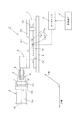
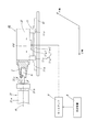
- the machine tool described in Patent Document 2 will be described with reference to FIG. 13.
- the machine tool 100 has a first guide path 101, which is a piston rod of a hydraulic cylinder 102.
- the tool post 104 connected to the guide 103 is guided to move in a direction perpendicular to the axis O of the workpiece W.
- the machine tool 100 has a vibration exciter 105, and the vibration exciter 105 detachably fixes a vibration mechanism that generates vibration in a feed direction parallel to the axis O of the workpiece W and the cutting tool 106.
- it is connected to the piston rod 108 of the feed cylinder 107 and can be moved in the feed direction by a second guide path 109 fixed to the tool post 104. Then, the workpiece W rotating around the axis O is cut by vibrating the machine tool 100 configured as described above.
- JP 2000-052101 A Japanese Patent Publication No.49-17790 JP-A-6-285701
- a machine tool that performs conventional cutting processes cuts the workpiece by moving a cutting tool such as a cutting tool in a relatively fixed direction, and effectively generates cutting heat and frictional heat generated at that time.
- a cutting tool such as a cutting tool
- cooling and lubrication could not be performed, which caused the cutting edge of the cutting tool to be remarkably worn, resulting in variations in work quality of the workpiece.
- chips generated when cutting are entangled with the cutting tool, resulting in a variation in quality and a fire.
- a machine tool with a vibration exciter attached to the cutting tool has the advantage of enabling cutting of difficult-to-cut materials, but has a problem that the work shape of the workpiece is limited. That is, since the machine tool 100 has the vibration exciter 105 attached, the cutting tool 106 can be moved only in the vertical direction and the horizontal direction, and the workpiece is intended to have the processed shape of the workpiece W shown in FIG. For example, when the arc portion WR of the workpiece W is cut, the machine tool 100 must be rotated in the direction of the arrow P10 for cutting. However, in reality, if the machine tool 100 is rotated in the direction of the arrow P10, it will interfere with the workpiece W and other machines not shown in FIG. It was physically impossible. Therefore, in the machine tool in which the vibration exciter is attached to the cutting tool, there is a problem that the processing shape of the workpiece is limited.
- this NC turning apparatus cuts a workpiece by cutting it into a somewhat long chip by repeating the operation of moving the tool by a predetermined distance, temporarily stopping it, and then reversing it by a predetermined distance by a servo motor. That's it. Therefore, it is conceivable to apply this operation and repeat the forward and backward movements without stopping the operation of the tool to cause the tool to be subjected to low-frequency vibration cutting.
- the present invention can stabilize the work quality of a workpiece mainly made of difficult-to-cut materials with high quality and suppress the occurrence of fire, and is practical and the work shape of the workpiece.
- the machine tool according to claim 1 includes a cutting tool holding means (cutting tool table 5, rotating mechanism 31) for holding a workpiece cutting tool (4), and a workpiece holding means (rotating mechanism) for holding a work (2). 3, work chuck mechanism 32), The cutting tool holding means (cutting tool table 5, rotating mechanism 31) or the work holding means (rotation) so as to feed the cutting tool (4) in a plurality of axial directions relative to the work (2).
- Mechanism 3, work chuck mechanism 32) is provided movably, The cutting tool holding means (cutting tool table 5, rotating mechanism 31) or the work holding so that the work (2) and the cutting tool (4) are relatively vibrated at a low frequency in a plurality of axial directions.
- a control mechanism (control device 8) for controlling the movement of the means (rotating mechanism 3, work chuck mechanism 32) is provided.
- a machine tool according to a second aspect is the machine tool according to the first aspect, wherein the cutting tool holding means (cutting tool table 5, rotating mechanism 31) is provided to be movable in a plurality of axial directions. It is a feature.
- a machine tool according to claim 3 is the machine tool according to claim 1, wherein the work holding means (the rotation mechanism 3 and the work chuck mechanism 32) are provided so as to be movable in a plurality of axial directions. It is said.
- the machine tool according to claim 4 is the machine tool according to claim 1, wherein the cutting tool holding means (cutting tool base 5) and the work holding means (rotating mechanism 3) are provided movably.
- the cutting tool holding means (cutting tool table 5) and the work holding means (rotating mechanism 3) move in cooperation to move the cutting tool (4) in a plurality of axes relative to the work (2). It is characterized by being fed in the direction.
- vibration cutting information storage means (vibration cutting information storage unit 83)
- the control mechanism (control device 8) is controlled based on data stored in the vibration cutting information storage means (vibration cutting information storage unit 83).
- control mechanism performs cutting so that the workpiece (2) and the cutting tool (4) are relatively vibrated at a low frequency in a plurality of axial directions.
- the movement of the tool holding means (cutting tool table 5, rotating mechanism 31) or the work holding means (rotating mechanism 3, work chuck mechanism 32) is controlled.
- cavitation occurs in the space (K) (see FIG. 1 and the like) generated in the work (2) and the cutting tool (4), and coolant used for cutting is sucked into the work (2) and the cutting tool (4).
- Cutting heat and frictional heat generated when processing (2) can be effectively cooled and lubricated. Therefore, according to the present invention, the machining quality of the workpiece can be stabilized.
- the chips of the workpiece (2) become powdery due to the low frequency vibration, and the cutting tools are less likely to get tangled. Therefore, the quality is stabilized, and furthermore, the occurrence of fire can be suppressed.
- control mechanism controls the workpiece (2) and the cutting tool (4) to vibrate at a low frequency in synchronization with a plurality of axial directions. Therefore, it is practical because it has a simple structure, and the working shape of the workpiece is not limited.
- the movement of the cutting tool holding means (cutting tool base 5, rotating mechanism 31) or the work holding means (rotating mechanism 3, work chuck mechanism 32) is controlled by the control mechanism (control device 8).
- the control mechanism control device 8
- the workpiece (2) and the cutting tool (4) are relatively fed in a plurality of axial directions, the workpiece (2) and the cutting tool (4) are caused to vibrate at low frequencies by being fed synchronously. Thereby, the low frequency vibration cutting which can cut
- the machine tool as described above can be provided with cutting tool holding means (cutting tool table 5, rotating mechanism 31) movably in a plurality of axial directions, like the machine tool according to the invention of claim 2.
- the work holding means (the rotation mechanism 3, the work chuck mechanism 32) can be provided so as to be movable in a plurality of axial directions.
- the cutting tool holding means (cutting tool base 5) and the work holding means (rotating mechanism 3) are provided movably, and the cutting tool holding means (cutting tool base 5) is provided.
- the work holding means (the rotation mechanism 3) move in cooperation, and the cutting tool (4) can be moved in a plurality of axial directions relative to the work (2).
- vibration cutting information storage means in which data for causing the workpiece (2) and the cutting tool (4) to vibrate at a low frequency as described above is stored in advance. If the vibration cutting information storage unit 83) is provided, the control mechanism (control device 8) can be controlled based on data stored in the vibration cutting information storage means (vibration cutting information storage unit 83). Thereby, low-frequency vibration cutting can be realized with an optimum vibration capable of finely dividing chips.
- the frequency is theoretically determined by the amplitude and the interpolation speed, but in reality, the relationship between the amplitude and the interpolation speed and the frequency varies depending on the machine characteristics of the machine tool (for example, mass on the table, motor characteristics, etc.). It changes and does not become a fixed relationship such as a proportional relationship, and a desired vibration (optimum frequency and amplitude) cannot be created by calculation on a desk. Also, if low-frequency vibration cutting is to be realized for the purpose of cutting chips, the rotation speed of the workpiece or the cutting tool is set so as not to synchronize with the low-frequency vibration cutting cycle. However, it is very difficult to calculate such a period by calculation.
- vibration cutting information storage means vibration cutting information storage unit 83. If it is controlled by the control mechanism (control device 8) based on the above, low-frequency vibration cutting can be realized with optimum vibration capable of finely cutting chips.
- the low frequency in this specification means the range larger than 0 Hz and 1000 Hz or less.
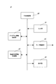
- FIG. 1 is a block diagram illustrating a schematic configuration of a machine tool according to a first embodiment of the present invention. It is a block diagram of the control device of the embodiment. It is a table figure stored in the vibration cutting information storage part of the embodiment. It is explanatory drawing which showed the case where the cutting tool which concerns on the same embodiment is moved from A point to B point by linear interpolation etc. It is a flowchart figure which shows the usage example of the machine tool which concerns on the same embodiment. It is a block diagram which shows schematic structure of the machine tool which concerns on 2nd Embodiment of this invention. It is a block diagram which shows schematic structure of the machine tool which concerns on 3rd Embodiment of this invention.
- a machine tool 1 is formed of a CNC lathe, and is provided on a rotation mechanism 3 that rotatably supports a workpiece 2 as a workpiece and a base 6 as shown in FIG.
- the cutting tool feed mechanism 7 on which a cutting tool base 5 for holding a cutting tool (a cutting tool in the drawing) 4 for cutting the workpiece 2 is placed, and the operation of the cutting tool feed mechanism 7 are represented by a servo amplifier 9.
- a control device 8 for controlling the cutting tool 4 to vibrate at a desired low frequency.
- FIG. 1 only the cutting tool feed mechanism 7 on the Z axis is shown, but a cutting tool feed mechanism on the orthogonal X axis is also provided.
- the rotation mechanism 3 has a spindle motor 3a, and a chuck mechanism 3c is rotatably attached to a main shaft 3b of the spindle motor 3a.
- the workpiece 2 as a workpiece is gripped by the chuck mechanism 3c, and the gripped workpiece 2 is driven to rotate around the rotation axis R by the rotational drive of the spindle motor 3a. Yes.
- the cutting tool feed mechanism 7 has a cutting tool feed drive motor 7a composed of a linear servo motor that is a drive source for feeding the cutting tool 4 so as to be movable back and forth with respect to the workpiece 2 (see arrow P1). Yes.
- the cutting tool feed drive motor 7a is composed of a mover 7a1 and a stator 7a2.
- the mover 7a1 is formed by winding an exciting coil around a magnetic structure, and the stator 7a2 A large number of magnets are arranged in the longitudinal direction.
- the movable element 7a1 is provided at the lower part of the table 7b on which the cutting tool table 5 is placed, and the stator 7a2 is provided at the upper part of the guide rail 7c provided on the base 6. .
- a pair of guides 7d for guiding the table 7b to move along the guide rails 7c is provided at the lower part of the table 7b.
- the servo amplifier 9 moves the current based on the command sent from the control device 8. It is sent to the child 7a1.
- the magnetic poles of the mover 7a1 and the stator 7b1 are attracted and repelled, so that thrust in the front-rear direction (see arrow P1) is generated, and the table 7b moves in the front-rear direction (see arrow P1) along with the thrust. Will be moved to.
- the pair of guides 7d are provided for the movement of the table 7b accompanying the thrust, the table 7b moves along the guide rails 7c by the pair of guides 7d.
- the cutting tool feed mechanism 7 can be moved with respect to the workpiece 2 so as to freely advance and retract (see arrow P1).
- a linear servo motor is used as the cutting tool feed drive motor 7a.
- the present invention is not limited to this, and any linear motor may be used.
- a servo motor may be used.
- a ball screw is used. For this reason, when backlash occurs when the cutting tool feed mechanism 7 is moving back and forth, vibration is absorbed, and therefore a linear motor capable of direct control that does not require a ball screw or the like is used. Is preferred.
- the control device 8 includes a central control unit 80 composed of a CPU and the like, an input unit 81 composed of a touch panel and the like, and program information for storing program information programmed by the user using the input unit 81.
- a motor control unit 84 that controls the operation of the cutting tool feed drive motor 7a via the servo amplifier 9, and a display unit 85 including a liquid crystal monitor or the like.
- the vibration cutting information storage unit 83 stores a vibration cutting information table VC_TBL shown in FIG. That is, in the vibration cutting information table VC_TBL, data (the cutting tool feed mechanism 7) corresponding to the program set values (the rotation speed (rpm) of the work 2 and the feed amount (mm) of the cutting tool 4 per rotation of the work 2). Advance amount (mm), retreat amount of cutting tool feed mechanism 7 (mm), advance speed of cutting tool feed mechanism 7 (mm / min), retreat speed of cutting tool feed mechanism 7 (mm / min), cutting tool 4 Vibration frequency (Hz)) is stored.
- the work 2 that is appropriate for the rotation speed 1000 (rpm) of the work 2 is set.
- the feed amount of the cutting tool 4 per one rotation three types of feed amounts of 0.005 (mm), 0.01 (mm), and 0.015 (mm) can be set.
- the advance amount (0.035) of the cutting tool feed mechanism 7 corresponding to these feed amounts (0.005 (mm), 0.01 (mm), 0.015 (mm)).
- the user programmed the rotation speed of the workpiece 2 to 1000 (rpm) using the input unit 81 and the feed amount of the cutting tool 4 per rotation of the workpiece 2 to 0.005 (mm). Then, the advance amount 0.035 (mm) of the cutting tool feed mechanism 7, the retract amount 0.03 (mm) of the cutting tool feed mechanism 7, the advance speed 290 (mm / min) of the cutting tool feed mechanism 7, the cutting tool feed
- the retracting speed 290 (mm / min) of the mechanism 7 is selected, and the motor control unit 84 controls the operation of the cutting tool feed driving motor 7a via the servo amplifier 9 based on the selected data. Will vibrate at low frequency.
- the vibration frequency 25 (Hz) of the cutting tool 4 stored in the vibration cutting information table VC_TBL is displayed on the display unit 85 and is not involved in the low-frequency vibration of the cutting tool 4 at all. Therefore, it is not necessary to store the vibration frequency of the cutting tool 4 in the vibration cutting information table VC_TBL, but the rotation number (rpm) of the workpiece 2 programmed by the user and the cutting tool 4 per one rotation of the workpiece 2 are stored. Since the vibration frequency (Hz) of the cutting tool 4 corresponding to the feed amount (mm) can be easily and easily confirmed, it is preferable to store the vibration frequency of the cutting tool 4.
- the values stored in the vibration cutting information table VC_TBL described in the present embodiment are merely examples, and various values corresponding to the machine characteristics of the machine tool can be stored in advance.
- the value corresponding to the machine characteristic of the machine tool is determined by collecting the experimental data by performing an operation experiment on the machine tool in advance.
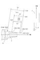
- the cutting tool 4 is synchronized with the two axis directions of the X axis and the Z axis from the point A (u0, w0) to the point B ( A method of moving to (U, W) will be described with reference to FIG.
- the point A indicates the current position of the cutting tool 4.
- the user uses the input unit 81 to create a program using the NC language. Specifically, the rotational speed of the workpiece 2 is input, and a vibration cutting command code for performing low frequency vibration cutting from normal cutting (conventional cutting) is input. As a matter of course, when the low frequency vibration cutting is not performed, the vibration cutting command code is not input.
- the user inputs the point B (U, W) that is the moving point of the cutting tool 4 using the input unit 81, and the cutting tool while performing direct interpolation when moving to the point B. 4 is moved, or the cutting tool 4 is moved while performing circular interpolation in the clockwise direction, or the cutting tool 4 is moved while performing circular interpolation in the counterclockwise direction, and circular interpolation is performed.
- the input of the radius and the input of the feed amount of the cutting tool 4 per rotation of the workpiece 2 are created by using NC language. If this program is specifically shown, it can be described as follows, for example.
- “S1000” is described to set the number of revolutions of the work 2 as 1000 (rpm). If “M123” is set, vibration cutting is set to ON, and if the cutting tool 4 is linearly interpolated to point B, “G1 XU ZW” is described, and “F0.01” is further described. Thus, the feed amount of the cutting tool 4 per rotation of the work 2 is set to 0.01 (mm).
- the cutting tool 4 is to be circularly interpolated (counterclockwise) up to point B, describe “G3 XU ZW” and “R10.0” to determine the arc radius for circular interpolation.
- the program is set to 10.0 (mm), and further, the feed amount of the cutting tool 4 per rotation of the workpiece 2 is set to 0.01 (mm) by describing “F0.01”. .
- vibration cutting command codes “M123” and “M456” may not be described.
- the central control unit 80 stores the created program in the program information storage unit 82 (step S1).
- “M123” and “M456” in the NC program are merely examples, and can be changed to arbitrary codes.
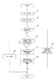
- step S2 After creating the program, the user issues an execution command for the created program using the input unit 81 (step S2). Thereby, the central control part 80 reads the program stored in the program information storage part 82, and confirms cutting mode (step S3).
- the central control unit 80 performs the programmed cutting.
- An interpolation trajectory calculation process is performed based on an interpolation method up to point B (U, W), which is the moving point of the tool 4, and the calculation result is output to the motor control unit 84.
- the motor control unit 84 that has received the information moves the cutting tool 4 from the point A (u0, w0) to the point B (U, W) based on the information via the servo amplifier 9 through the cutting tool feed drive motor 7a. Is controlled to move along the interpolation trajectory (step S4).
- the central control unit 80 ends the information processing.
- step S3 YES
- the central control unit 80 performs the vibration cutting information storage unit 83. It is confirmed whether or not the number of rotations of the workpiece 2 and the feed amount of the cutting tool 4 per rotation of the workpiece 2 are programmed so as to coincide with the program set value of the vibration cutting information table VC_TBL stored in (Step). S5). If the program setting that matches the program setting value of the vibration cutting information table VC_TBL is not made (step S5: NO), the central control unit 80 gives a warning that the appropriate value is not set in the display unit 85. Display (step S6), and the process ends.
- the central control unit 80 displays a warning on the display unit 85 that an appropriate value is not programmed.
- the user can reliably program an appropriate feed amount of the cutting tool 4 per rotation of the workpiece 2.
- the central control unit 80 will perform the vibration cutting stored in the vibration cutting information storage unit 83. From the information table VC_TBL, the amount of advance of the cutting tool feed mechanism 7 corresponding to the number of revolutions of the workpiece 2 programmed by the user using the input unit 81 and the amount of feed of the cutting tool 4 per revolution of the workpiece 2, and the cutting tool feed The retraction amount of the mechanism 7, the forward speed of the cutting tool feed mechanism 7, the reverse speed of the cutting tool feed mechanism 7, and the vibration frequency of the cutting tool 4 are selected.
- the central control unit 80 stores the program information of the interpolation method up to point B which is the moving point of the cutting tool 4 stored in the program information storage unit 82 and the selected information (advancing amount of the cutting tool feed mechanism 7). , The amount of retreat of the cutting tool feed mechanism 7, the forward speed of the cutting tool feed mechanism 7, and the reverse speed of the cutting tool feed mechanism 7) are used to calculate forward and backward motions along the interpolation trajectory.
- the central control unit 80 outputs the calculation result to the motor control unit 84 and outputs the vibration frequency of the selected cutting tool 4 to the display unit 85 together with the calculation result. (Step S7).
- the motor control unit 84 that has received such a calculation result controls the cutting tool feed drive motor 7a via the servo amplifier 9 based on the information, and vibrates the cutting tool 4 at a low frequency. That is, the motor control unit 84 performs a process of repeating the operation of moving the cutting tool feed mechanism 7 forward and backward based on the calculation result. As a result, the cutting tool 4 is alternately moved to the solid line position and the broken line position as shown in FIG. 1 and vibrates at a low frequency. In this way, the motor control unit 84 synchronizes the cutting tool 4 in the two axis directions of the X axis and the Z axis, and repeats the forward and backward movement along the interpolation trajectory to vibrate A point (u0, w0).
- step S8 To point B (U, W) (step S8). Thereby, it can process with the cutting tool 4 which made the workpiece
- the cutting tool feed drive motor 7a which is the drive source of the cutting tool feed mechanism 7 that feeds the cutting tool 4 that cuts the workpiece 2 is controlled by the control device 8 with the cutting tool 4 described above. Is controlled to vibrate at low frequency. As a result, as shown in FIG. 1, cavitation occurs in the space K generated in the workpiece 2 and the cutting tool 4, and coolant or the like used when cutting is sucked there. It is possible to effectively cool and lubricate the cutting heat and frictional heat generated in the heat. Therefore, according to this embodiment, the processing quality of the workpiece can be stabilized.
- the cutting tool 4 cuts the workpiece 2 while vibrating at a low frequency, the chips of the workpiece 2 are powdered by the low-frequency vibration, and the cutting tools are less likely to get tangled. Therefore, quality is stabilized and the occurrence of fire can be suppressed.
- the cutting tool feed drive motor 7a is only controlled using the control device 8 when the cutting tool 4 is vibrated at low frequency, it is practical because it has a simple structure. is there.
- the cutting tool feed drive motor 7a can be controlled in the interpolation direction using the control device 8, the workpiece can be machined freely. Therefore, there is an effect that the processing shape of the workpiece is not limited.
- the cutting tool 4 is controlled by the control device 8 to vibrate at low frequency in synchronization with a plurality of axial directions, low frequency vibration cutting capable of finely dividing chips is realized. Can do.
- the vibration cutting information storage unit 83 synchronizes the cutting tool 4 in a plurality of axial directions according to the rotation speed of the work 2 and the feed amount of the cutting tool 4 per rotation of the work 2. Therefore, low frequency vibration cutting can be realized with optimum vibration capable of finely dividing chips.
- the user when creating the NC program, the user adds a vibration cutting command code (vibration cutting ON code, vibration cutting OFF code) in addition to a program for executing normal conventional cutting.
- the low frequency vibration cutting can be executed with the optimum vibration only by creating the program.
- linear interpolation and circular interpolation are exemplified as the interpolation method, but it is needless to say that any interpolation method such as taper interpolation may be used.
- a machine tool 10 is composed of a CNC lathe. As shown in FIG. 6, a cutting tool base 5 that holds a cutting tool 4 that cuts a workpiece 2 that is a workpiece, and the workpiece 2 described above. A rotating mechanism 3 that rotatably supports the workpiece, a workpiece feeding mechanism 11 that feeds and moves the workpiece 2 provided below the rotating mechanism 3 with respect to the cutting tool 4 (see arrow P2), and the workpiece A control device 8 is provided for controlling the operation of the feed mechanism 11 through a servo amplifier 9 so that the workpiece 2 vibrates at a desired low frequency. In FIG. 6, only the workpiece feeding mechanism 11 on the Z axis is shown, but a workpiece feeding mechanism on the orthogonal X axis is also provided.
- the work feed mechanism 11 has a work feed drive motor 11a composed of a linear servo motor that is a drive source that feeds the work 2 so as to advance and retreat with respect to the cutting tool 4 (see arrow P2).
- the workpiece feed drive motor 11a is composed of a mover 11a1 and a stator 11a2.
- the mover 11a1 is formed by winding an exciting coil around a magnetic structure, and the stator 11a2 includes a large number of stators 11a2.
- the magnets are arranged in the longitudinal direction.
- the movable element 11a1 is provided at the lower part of the spindle motor 3a of the rotating mechanism 3, and the stator 11a2 is provided at the upper part of the guide rail 11b provided at the upper end of the base 12.
- a pair of guides 11c for guiding the spindle motor 3a to move along the guide rail 11b is provided below the spindle motor 3a.
- the cutting tool base 5 is provided at the upper other end of the base 12.
- the servo amplifier 9 moves a current based on a command sent from the control device 8. Send to child 11a1.
- the magnetic poles of the mover 11a1 and the stator 11b1 perform attraction and repulsion, so that a thrust in the front-rear direction (see arrow P2) is generated, and the spindle motor 3a moves in the front-rear direction (see arrow P2) along with the thrust. ) Will be moved.
- a pair of guides 11c are provided.
- the spindle motor 3a is moved along the guide rail 11b by the pair of guides 11c. . Therefore, the workpiece feeding mechanism 11 can be moved with respect to the cutting tool 4 so as to freely advance and retract (see arrow P2).
- a linear servo motor is used as the workpiece feed drive motor 11a.
- the present invention is not limited to this, and any linear motor may be used.
- a servo motor may be used in addition to the linear motor, but when using the servo motor, a ball screw is used, so backlash occurs when the workpiece feeding mechanism is moving back and forth. Therefore, it is preferable to use a linear motor capable of direct control that does not require a ball screw or the like.
- the workpiece 2 of the machine tool 10 configured as described above is synchronized in a plurality of axial directions (in the drawing, two axial directions of the X axis and the Z axis), and is moved to a solid line position and a broken line position as shown in FIG.
- a method of cutting with the cutting tool 4 while alternately moving and vibrating will be described. Since this method is almost the same as that of the first embodiment, only differences from the first embodiment will be described.
- the vibration cutting information storage unit 83 stores data for feeding the workpiece 2 in synchronization with a plurality of axial directions (in the drawing, two axial directions of the X axis and the Z axis) to vibrate at low frequency, that is, a vibration cutting information table.
- VC_TBL (see FIG. 3) is stored.
- this vibration cutting information table VC_TBL (see FIG. 3), the number of rotations (rpm) of the workpiece 2 programmed by the user using the input unit 81 and the feed amount (mm) of the workpiece 2 per one rotation of the workpiece 2 are set.
- the central control unit 80 allows the work feed mechanism 11 to move forward, the work amount corresponding to the rotation speed of the work 2 programmed by the user using the input unit 81 and the feed amount of the work 2 per one rotation of the work 2.
- the reverse amount of the feed mechanism 11, the forward speed of the work feed mechanism 11, the reverse speed of the work feed mechanism 11, and the vibration frequency of the work 2 are selected.
- the central control unit 80 stores the program information of the interpolation method up to the point B which is the moving point of the workpiece 2 stored in the program information storage unit 82 and the selected information (advancing amount of the workpiece feeding mechanism 11, workpiece feeding). Based on the reverse amount of the mechanism 11, the forward speed of the work feed mechanism 11, and the reverse speed of the work feed mechanism 11, calculation processing of forward and backward movement along the interpolation trajectory is performed.
- the central control unit 80 outputs the calculation result to the motor control unit 84 and outputs the vibration frequency of the selected workpiece 2 to the display unit 85 together with the calculation result.
- the motor control unit 84 synchronizes the workpiece 2 in a plurality of axial directions (in the drawing, two axial directions of the X axis and the Z axis), as shown in FIG. Controls to move alternately. Thereby, the workpiece 2 is cut by the cutting tool 4 while vibrating at a low frequency. Note that the vibration frequency of the work 2 output to the display unit 85 is displayed on the display unit 85.
- the present embodiment and the first embodiment differ only in the object to be vibrated at a low frequency, the present embodiment has the same effect as the first embodiment.
- the machine tool 20 is composed of a CNC lathe. As shown in FIG. 7, on the Z-axis, a rotating mechanism 3 that rotatably supports a workpiece 2 that is a workpiece, and its rotation. A work feed mechanism 11 provided at the lower part of the mechanism 3 and for feeding the work 2 provided on the base 21 so as to freely move back and forth (see arrow P3) is provided. On the X axis perpendicular to the Z axis, there is provided a cutting tool feed mechanism 7 which is provided on the base 22 and feeds the cutting tool 4 for cutting the workpiece 2 so as to freely move back and forth (see arrow P4). ing.
- the machine tool 20 controls the operations of the cutting tool feeding mechanism 7 and the workpiece feeding mechanism 11 through the servo amplifier 9 so that the cutting tool 4 and the workpiece 2 vibrate at a desired low frequency.
- a control device 8 is provided.
- FIG. 7 only the workpiece feeding mechanism 11 on the Z axis and the cutting tool feeding mechanism 7 on the X axis are shown, but there are also a workpiece feeding mechanism and a cutting tool feeding mechanism on the Y axis orthogonal to the XZ axis. is doing.
- the workpiece 2 and the cutting tool 4 of the machine tool 20 configured in this way are synchronized in cooperation in a plurality of axial directions (in the drawing, three axial directions of the X axis, the Z axis, and the Y axis).
- vibration cutting information storage unit 83 data for causing the workpiece 2 and the cutting tool 4 to feed and synchronize at a low frequency in a plurality of axial directions (in the drawing, three axial directions of the X, Z, and Y axes). That is, a vibration cutting information table VC_TBL (see FIG. 3) is stored. In this vibration cutting information table VC_TBL (see FIG. 3) is stored. In this vibration cutting information table VC_TBL (see FIG.
- the rotation number (rpm) of the workpiece 2 programmed by the user using the input unit 81 and the feed of the cutting tool 4 and the workpiece 2 per one rotation of the workpiece 2
- the amount of advance (mm) of the cutting tool feed mechanism 7 and the work feed mechanism 11 corresponding to the amount (mm), the amount of retreat (mm) of the cutting tool feed mechanism 7 and the work feed mechanism 11, the cutting tool feed mechanism 7 and the work feed mechanism 11 forward speed (mm / min), the retraction speed (mm / min) of the cutting tool feed mechanism 7 and the work feed mechanism 11, and the vibration frequency (Hz) of the cutting tool 4 and the work 2 are stored.
- the central control unit 80 has a cutting tool feeding mechanism corresponding to the rotation number of the workpiece 2 programmed by the user using the input unit 81 and the cutting tool 4 and the feeding amount of the workpiece 2 per one rotation of the workpiece 2. 7 and the advance amount of the work feed mechanism 11, the retreat amount of the cutting tool feed mechanism 7 and the work feed mechanism 11, the advance speed of the cutting tool feed mechanism 7 and the work feed mechanism 11, the retreat of the cutting tool feed mechanism 7 and the work feed mechanism 11. Select the speed, vibration frequency of the cutting tool 4 and the workpiece 2.
- the central control unit 80 stores the program information of the interpolation method up to the point B which is the moving point of the workpiece 2 and the cutting tool 4 stored in the program information storage unit 82 and the selected information (the cutting tool feed mechanism 7 and (Advance amount of work feed mechanism 11, retraction amount of cutting tool feed mechanism 7 and work feed mechanism 11, advance speed of cutting tool feed mechanism 7 and work feed mechanism 11, retreat speed of cutting tool feed mechanism 7 and work feed mechanism 11)
- the central control unit 80 outputs the calculation result to the motor control unit 84 and outputs the vibration frequency of the selected cutting tool 4 and workpiece 2 to the display unit 85 together with the calculation result.
- the motor control unit 84 controls the cutting tool 4 and the workpiece 2 to alternately move to the solid line position and the broken line position as shown in FIG. 7 based on the calculation result. Thereby, the workpiece 2 is cut by the cutting tool 4. Note that the vibration frequencies of the cutting tool 4 and the workpiece 2 output to the display unit 85 are displayed on the display unit 85.
- FIG. 8 is a diagram for explaining a procedure for cutting the workpiece 2 using the cutting tool 4 while the two axes of the X axis and the Z axis are synchronized in cooperation.
- the workpiece 2 is moved along the Z axis by a distance of TL1Z from the point TP1Z to the point TP10Z
- the cutting tool 4 is further moved along the X axis by a distance of TL1X from the point TP1X to the point TP10X.
- the workpiece 2 and the cutting tool 4 are moved forward by a distance of TL2 from the point (TP1X, TP1Z) to the point (TP2X, TP2Z), the workpiece 2 is advanced by a distance of TL2Z along the Z axis.
- the cutting tool 4 is moved forward by a distance of TL2X along the X axis. Thereby, the workpiece 2 and the cutting tool 4 can be moved forward by a distance of TL2 in cooperation with the XZ2 axis.
- the workpiece 2 and the cutting tool 4 are moved backward by the distance of TL3 to the point (TP3X, TP3Z) after reaching the point (TP2X, TP2Z), the workpiece 2 is moved along the Z axis to the TL3Z.
- the cutting tool 4 is moved backward by the distance, and the cutting tool 4 is moved backward by the distance of TL3X along the X axis.
- the workpiece 2 and the cutting tool 4 can be moved backward by a distance of TL3 in cooperation with the XZ2 axis.
- the workpiece 2 and the cutting tool 4 are moved forward by a distance of TL2, that is, the workpiece 2 is moved forward by a distance of TL2Z along the Z axis, and the cutting tool 4 is moved by a distance of TL2X along the X axis.
- the workpiece 2 and the cutting tool 4 are moved backward by a distance of TL3, that is, the workpiece 2 is moved backward by a distance of TL3Z along the Z axis, and the cutting tool 4 is moved along the X axis.
- the cutting tool 4 and the workpiece 2 are moved by the distance of TL1 from the point (TP1X, TP1Z) to the point (TP10X, TP10Z).
- the workpiece 2 can be cut by the cutting tool 4 along a straight line (taper) connecting the position of the point (TP1X, TP1Z) to the point (TP10X, TP10Z).
- the cutting tool 4 and the workpiece 2 that vibrate at low frequency do not operate individually, but operate while the two axes of the X axis and the Z axis cooperate and synchronize. Therefore, the operations of the cutting tool 4 and the workpiece 2 appear to be stopped when viewed from the cutting tool 4 side, and the cutting tool 4 appears to be stopped when viewed from the workpiece 2 side. Looks like. Therefore, the operation in this embodiment is substantially the same as the operation of the cutting tool 4 shown in the first embodiment or the operation of the workpiece 2 shown in the second embodiment. In the case of three axes including the Y axis orthogonal to the XZ axis, the three axes operate in cooperation and in synchronization.
- the present embodiment and the first embodiment differ only in the object to be vibrated at a low frequency, the present embodiment has the same effect as the first embodiment.
- the machine tool 30 according to the fourth embodiment shown in FIG. 9 includes a CNC lathe, a work chuck mechanism 32 that supports the work 2 that is a workpiece, and a cutting tool that cuts the work 2. And a cutting tool feed mechanism 34 that is provided below the rotation mechanism 31 and feeds the cutting tool 4 provided on the base 33 so as to freely move forward and backward (see arrow P5). And are provided.
- the machine tool 30 includes a control device 8 that controls the operation of the cutting tool feed mechanism 34 through the servo amplifier 9 so that the cutting tool 4 vibrates at a desired low frequency.
- FIG. 9 only the cutting tool feed mechanism 34 on the Z axis is shown, but a cutting tool feed mechanism on the orthogonal X axis is also provided.
- the configuration of the cutting tool feed mechanism 34 is substantially the same as that of the workpiece feed mechanism 11, and only the workpiece feed drive motor 11a is replaced with the cutting tool feed drive motor 7a. For this reason, the same reference numerals are given and description thereof is omitted.
- the rotation mechanism 31 has a spindle motor 31a, and a cutting tool chuck mechanism 31c is rotatably attached to a main shaft 31b of the spindle motor 31a.
- the cutting tool chuck mechanism 31c grips the cutting tool 4, and the gripped cutting tool 4 is driven to rotate about the rotation axis R by the rotational drive of the spindle motor 31a.
- the cutting tool 4 of the machine tool 30 comprised in this way is moved to a solid line position and a broken line position alternately, and the method of cutting the workpiece
- the program setting value corresponding to the data stored in the vibration cutting information table VC_TBL (see FIG.
- the vibration cutting information storage unit 83 stored in the vibration cutting information storage unit 83 is almost the same as that of the embodiment, and the user inputs the input unit 81.
- the only difference is that the number of revolutions (rpm) of the cutting tool 4 programmed using and the feed amount (mm) of the cutting tool 4 per revolution of the cutting tool 4 are different.
- a machine tool 40 according to the fifth embodiment shown in FIG. 10 includes a CNC lathe, a work chuck mechanism 32 that supports a work 2 that is a workpiece, and a cutting tool that cuts the work 2.
- a rotating mechanism 31 that rotatably supports the workpiece 4, and a workpiece feeding mechanism 11 that is provided below the workpiece chuck mechanism 32 and that moves the workpiece 2 provided on the base 41 forward and backward (see arrow P6).
- the machine tool 40 is provided with a control device 8 for controlling the operation of the workpiece feeding mechanism 11 via the servo amplifier 9 so that the workpiece 2 vibrates at a desired low frequency.
- the work 2 of the machine tool 40 configured in this way is vibrated by moving the work 2 alternately between the solid line position and the broken line position as shown in FIG. 10 in substantially the same manner as in the second embodiment.
- the program set value corresponding to the data stored in the vibration cutting information table VC_TBL (see FIG. 3) stored in the storage unit 83 is the rotational speed of the cutting tool 4 programmed by the user using the input unit 81 ( rpm) and the feed amount (mm) of the workpiece 2 per rotation of the cutting tool 4 are the same except for the difference.
- the workpiece 2 was processed using the machine tool 20 according to the third embodiment.
- the machine tool 20 an L16 CNC automatic lathe manufactured by Citizen Machinery was used. Further, as the work 2, a bar of SKD11- ⁇ 12.0 was used, and the cutting tool 4 was a bit having a dimension of 12 mm.
- the cutting tool feed mechanism 7 a combination of a ball screw and a servo motor was used. Then, the rotation speed of the workpiece 2 was set to 600 rpm, and the cutting tool 4 and the feed amount of the workpiece 2 per rotation of the workpiece 2 were each set to 0.01 mm, and the workpiece 2 was cut. As a result, the processed product shown in FIG. 11 could be created.
- the amplitude of the low frequency vibrations of the cutting tool 4 and the workpiece 2 corresponding to the program set values is set to 0.03 and the frequency is set to 9 Hz, respectively.
- the low-frequency vibration cutting has a lower cutting resistance and the machining performance is significantly better than the conventional cutting.
- the machine tool 100 in which the vibration exciter is attached to the cutting tool as shown in FIG. 13 has the above-described problems, the tapered shape of the tip portion of the processed product shown in FIG. 11 is processed. I can't.
- Example 2 Next, using the machine tool 1 according to the first embodiment, the workpiece 2 was machined to produce a workpiece shown in FIG. 12 by low-frequency vibration cutting.
- the machine tool 1 an NL-10 CNC lathe manufactured by Citizen Machinery was used.
- the workpiece 2 was a rod of ⁇ 10-SUS304, and the cutting tool 4 was DCGT11T304ER-U-PR930 manufactured by Kyocera Corporation. Further, as the cutting tool feed mechanism 7, a linear servo motor manufactured by Mitsubishi Corporation was used.
- the rotational speed of the workpiece 2 is set to 3750 rpm
- the feed amount of the cutting tool 4 per rotation of the workpiece 2 is set to 0.01 mm
- the coolant is Suncut EF-5N (non-water-soluble) manufactured by Nippon Grease Co., Ltd. Sex).
- the amplitude of the low frequency vibration of the cutting tool 4 corresponding to the program set value is set to 0.03 and the frequency is set to 48 Hz.
- the workpiece 2 was processed by conventional cutting using the machine tool 1 according to the first embodiment to produce a processed product shown in FIG.
- the machine tool an NL-10 CNC lathe manufactured by Citizen Machinery was used.
- the workpiece 2 was a rod of ⁇ 10-SUS304, and the cutting tool 4 was DCGT11T304ER-U-PR930 manufactured by Kyocera Corporation.
- the cutting tool feed mechanism 7 a linear servo motor manufactured by Mitsubishi Corporation was used. Then, the feed amount was set to 28 mm / min so that the cutting time was the same as that of the low frequency vibration cutting of Example 2 above.
- As a coolant Suncut EF-5N (water-insoluble) manufactured by Nippon Grease Co., Ltd. was used.
Abstract
主に難削材からなるワークの加工品質を高品位に安定化させることができると共に火災発生を抑制し、なお且つ、実用的で、ワークの加工形状が限定されず、しかも、切削工具及び/又はワークを複数軸で低周波振動させたとしても切屑を細かく分断できる低周波振動切削を実現することができる工作機械を提供することを目的としている。 この目的を達成するため、工作機械は、ワーク加工用の切削工具(4)を保持する切削工具台(5)と、ワーク(2)を保持する回転機構3とを備え、前記切削工具(4)を前記ワーク(2)に対して相対的に複数軸方向に送り動作させるように、前記切削工具台(5)又は前記回転機構(3)を移動自在に設け、前記ワーク(2)と前記切削工具(4)とを相対的に複数軸方向に同期して低周波振動させるように、前記切削工具台(5)又は前記回転機構(3)の移動を制御する制御装置(8)を設けている。
Description
本発明は、切削工具又はワークを回転させてワークの切削加工を行う工作機械に関する。より詳しくは、切削工具及び/又はワークを低周波振動させてワークを切削加工する工作機械に関する。
従来の工作機械として、ワークに対してバイト等の切削工具を相対的に一定の方向に進行させて上記ワークを切削加工する、いわゆる慣用切削加工を行う工作機械が知られている。また一方、切削工具の刃先に圧電素子を用いて超音波領域の振動を与えながらワークを切削加工する、いわゆる超音波振動切削加工を行う工作機械も知られている(例えば、特許文献1)。そしてさらには、特許文献2に記載のように、切削工具に加振機を取付ける工作機械も知られている。
この特許文献2に記載の工作機械を、図13を参照して説明すれば、当該工作機械100は、第1案内路101を有し、この第1案内路101は、油圧シリンダ102のピストンロッド103と連結した刃物台104をワークWの軸心Oと直角の向きに移動させるように案内している。また工作機械100は、加振機105を有し、この加振機105はワークWの軸心Oと平行な送り方向の向きに振動を発生させる振動機構と、切削工具106を着脱自在に固定する装置とを有し、そしてさらに、送りシリンダ107のピストンロッド108と連結して上記刃物台104に固着された第2案内路109にて送り方向の向きに移動可能となっている。そして、このように構成される工作機械100を振動させることによって、軸心O周りに回転しているワークWの切削加工が行われるというものである。
しかしながら、従来の工作機械には以下のような問題があった。すなわち、慣用切削加工を行う工作機械は、バイト等の切削工具を相対的に一定の方向に進行させて上記ワークを切削加工するのであるが、その際発生する切削熱や摩擦熱を効果的に冷却及び潤滑させることができず、それが原因で切削工具の刃先を著しく摩耗させてしまい、ワークの加工品質にばらつきを生じさせてしまうという問題があった。さらに、切削加工する際発生する切屑が上記切削工具に絡まり、それが原因で品質にばらつきが生じるばかりか火災が発生するという問題もあった。
一方、超音波振動切削加工を行う工作機械は、難削材の切削加工を可能にするという利点があるものの加工時間が大幅に掛かるばかりか、非常に高価であり、さらには、圧電素子を用いているため切削工具を工作機械に取り付けるためのアダプターの役割を持つツーリングの設置箇所に制約が生じる等の問題があった。そのため、上記超音波振動切削加工を行う工作機械は、実用性に欠けるという問題があった。
また一方、切削工具に加振機を取付けた工作機械は、難削材の切削加工を可能にするという利点があるものの、ワークの加工形状が限定されてしまうという問題があった。すなわち、工作機械100は、加振機105を取り付けているため、切削工具106を垂直方向と水平方向にしか移動させることができず、ワークを図13に示すワークWの加工形状にしようとすれば、ワークWの円弧部WRを切削加工する際、矢印P10の向きに工作機械100を回転させて切削加工しなければならない。しかしながら、実際のところ、工作機械100を矢印P10方向に回転させようとすれば、ワークWや、図13には図示していない他の機械に干渉してしまい、矢印P10方向に回転させることは物理的に不可能であった。それゆえ、切削工具に加振機を取付けた工作機械では、ワークの加工形状が限定されてしまうという問題があった。
そこで、上記のような問題点を解決すべく、特許文献3に記載のようなNC旋削加工装置を用いて低周波振動切削をさせるように設計変更することも考えられる。すなわち、このNC旋削加工装置は、サーボモータによって、工具を所定距離だけ移動させて一旦停止させ、さらに所定距離だけリバースさせるという動作を繰り返すことによって、ある程度長い切屑に分断し、ワークを切削加工するというものである。そこで、この動作を応用し、工具の動作を停止させずに前進後退を繰り返し、上記工具を低周波振動切削させることも考えられる。
しかしながら、上記のようなNC旋削加工装置を複数軸で単に低周波振動させようとすると、思うような制御ができず、低周波振動を実現することができない、すなわち、切屑を細かく分断できるような低周波振動切削を実現することができないという問題があった。
そこで本発明は、上記問題点に鑑み、主に難削材からなるワークの加工品質を高品位に安定化させることができると共に火災発生を抑制し、なお且つ、実用的で、ワークの加工形状が限定されず、しかも、切削工具及び/又はワークを複数軸で低周波振動させたとしても、切屑を細かく分断できる低周波振動切削を実現することができる工作機械を提供することを目的としている。
上記本発明の目的は、以下の手段によって達成される。なお、括弧内は、後述する実施形態の参照符号を付したものであるが、本発明はこれに限定されるものではない。
請求項1に係る工作機械は、ワーク加工用の切削工具(4)を保持する切削工具保持手段(切削工具台5,回転機構31)と、ワーク(2)を保持するワーク保持手段(回転機構3,ワークチャック機構32)とを備え、
前記切削工具(4)を前記ワーク(2)に対して相対的に複数軸方向に送り動作させるように、前記切削工具保持手段(切削工具台5,回転機構31)又は前記ワーク保持手段(回転機構3,ワークチャック機構32)を移動自在に設け、
前記ワーク(2)と前記切削工具(4)とを相対的に複数軸方向に同期して低周波振動させるように、前記切削工具保持手段(切削工具台5,回転機構31)又は前記ワーク保持手段(回転機構3,ワークチャック機構32)の移動を制御する制御機構(制御装置8)を設けてなることを特徴としている。
前記切削工具(4)を前記ワーク(2)に対して相対的に複数軸方向に送り動作させるように、前記切削工具保持手段(切削工具台5,回転機構31)又は前記ワーク保持手段(回転機構3,ワークチャック機構32)を移動自在に設け、
前記ワーク(2)と前記切削工具(4)とを相対的に複数軸方向に同期して低周波振動させるように、前記切削工具保持手段(切削工具台5,回転機構31)又は前記ワーク保持手段(回転機構3,ワークチャック機構32)の移動を制御する制御機構(制御装置8)を設けてなることを特徴としている。
一方、請求項2に係る工作機械は、上記請求項1に記載の工作機械において、前記切削工具保持手段(切削工具台5,回転機構31)を複数軸方向に移動自在に設けてなることを特徴としている。
また、請求項3に係る工作機械は、上記請求項1に記載の工作機械において、前記ワーク保持手段(回転機構3,ワークチャック機構32)を複数軸方向に移動自在に設けてなることを特徴としている。
また一方、請求項4に係る工作機械は、上記請求項1に記載の工作機械において、前記切削工具保持手段(切削工具台5)及び前記ワーク保持手段(回転機構3)を移動自在に設け、前記切削工具保持手段(切削工具台5)と前記ワーク保持手段(回転機構3)とが協働して移動し、前記切削工具(4)を前記ワーク(2)に対して相対的に複数軸方向に送り動作させてなることを特徴としている。
他方、請求項5に係る工作機械は、上記請求項1に記載の工作機械において、前記ワーク(2)と前記切削工具(4)とを前記低周波振動させるためのデータが予め格納されている振動切削情報格納手段(振動切削情報格納部83)を設け、
前記制御機構(制御装置8)は、前記振動切削情報格納手段(振動切削情報格納部83)に格納されているデータに基づいて制御してなることを特徴としている。
前記制御機構(制御装置8)は、前記振動切削情報格納手段(振動切削情報格納部83)に格納されているデータに基づいて制御してなることを特徴としている。
次に、本発明の効果について説明する。なお、括弧内は、後述する実施形態の参照符号を付したものであるが、本発明はこれに限定されるものではない。
請求項1の発明にかかる工作機械では、制御機構(制御装置8)によって、ワーク(2)と切削工具(4)とを相対的に複数軸方向に同期して低周波振動させるように、切削工具保持手段(切削工具台5,回転機構31)又はワーク保持手段(回転機構3,ワークチャック機構32)の移動を制御する。これにより、ワーク(2)と切削工具(4)内に生じる空間(K)(図1等参照)にキャビテーションが発生し、そこに切削加工を行う際使用されるクーラント等が吸い込まれるため、ワーク(2)を加工する際発生する切削熱や摩擦熱を効果的に冷却及び潤滑させることができる。そのため、本発明によればワークの加工品質を安定させることができる。
また、本発明によれば、ワーク(2)を切削工具(4)によって切削加工する際、低周波振動によってワーク(2)の切屑が粉状となり、切削工具に切屑が絡まりにくくなる。それゆえ、品質が安定し、さらには、火災の発生を抑制することができる。
さらに、本発明によれば、ワーク(2)と切削工具(4)とを相対的に複数軸方向に同期して低周波振動させるにあたって、制御機構(制御装置8)を用いて制御しているだけであるから、簡便な構造であるため実用的であり、なお且つ、ワークの加工形状が限定されないという効果を奏する。
そして、本発明によれば、制御機構(制御装置8)によって、切削工具保持手段(切削工具台5,回転機構31)又はワーク保持手段(回転機構3,ワークチャック機構32)の移動を制御し、ワーク(2)と切削工具(4)とを相対的に複数軸方向に送り動作させる際、同期して送り動作させて低周波振動させている。これにより、切屑を細かく分断できる低周波振動切削を実現することができる。
また、上記のような工作機械を、請求項2の発明にかかる工作機械のように、切削工具保持手段(切削工具台5,回転機構31)を複数軸方向に移動自在に設けることもできる。また、請求項3の発明にかかる工作機械のように、ワーク保持手段(回転機構3,ワークチャック機構32)を複数軸方向に移動自在に設けることもできる。さらには、請求項4の発明に係る工作機械のように、切削工具保持手段(切削工具台5)及びワーク保持手段(回転機構3)を移動自在に設け、切削工具保持手段(切削工具台5)とワーク保持手段(回転機構3)とが協働して移動し、切削工具(4)をワーク(2)に対して相対的に複数軸方向に送り動作させることもできる。
一方、請求項5の発明にかかる工作機械のように、ワーク(2)と切削工具(4)とを上記のように低周波振動させるためのデータが予め格納されている振動切削情報格納手段(振動切削情報格納部83)を設ければ、上記制御機構(制御装置8)は、振動切削情報格納手段(振動切削情報格納部83)に格納されているデータに基づいて制御することができる。これにより、切屑を細かく分断できる最適な振動で低周波振動切削を実現することができる。すなわち、周波数は、理論上、振幅とその補間速度によって決定するが、実際は、振幅やその補間速度と周波数の関係は工作機械の機械特性(例えばテーブル上の質量やモータ特性等)によって種々様々に変化し、比例関係のような一定の関係になっておらず、机上の計算では所望の振動(最適な周波数及び振幅)を作成することができない。また、切屑を分断することを目的として、低周波振動切削を実現させようとすれば、ワークの回転数又は切削工具の回転数と低周波振動切削する際の周期とを同期させないように設定しなければならないが、そのような周期を計算で算出するのは非常に困難である。それゆえ、振動切削情報格納手段(振動切削情報格納部83)に、ワーク(2)と切削工具(4)とを上記のように低周波振動させるためのデータを予め格納しておき、そのデータに基づいて、上記制御機構(制御装置8)にて制御させれば、切屑を細かく分断できる最適な振動で低周波振動切削を実現することができる。
なお、本明細書における低周波とは、0Hzより大きく1000Hz以下の範囲をいうものである。
<第1実施形態>
以下、本発明に係る第1実施形態について、図1~図5を参照して具体的に説明する。
以下、本発明に係る第1実施形態について、図1~図5を参照して具体的に説明する。
本実施形態に係る工作機械1は、CNC旋盤からなるもので、図1に示すように、被加工物であるワーク2を回転自在に支持する回転機構3と、ベース6上に設けられ、なお且つ、上記ワーク2を切削加工する切削工具(図示ではバイト)4を保持する切削工具台5が載置されてなる切削工具送り機構7と、その切削工具送り機構7の動作を、サーボアンプ9を介して、切削工具4が所望の低周波振動をするように制御する制御装置8とを備えている。なお、図1では、Z軸上の切削工具送り機構7しか図示していないが、直交するX軸上の切削工具送り機構も有している。
上記回転機構3は、スピンドルモータ3aを有し、そのスピンドルモータ3aの主軸3bにはチャック機構3cが回転可能に取り付けられている。そして、そのチャック機構3cには被加工物であるワーク2が掴時されており、この掴持されたワーク2は、スピンドルモータ3aの回転駆動により回転軸R周りで回転駆動するようになっている。
一方、上記切削工具送り機構7は、ワーク2に対して進退自在(矢印P1参照)に切削工具4の送り動作をさせる駆動源であるリニアサーボモータからなる切削工具送り駆動モータ7aを有している。この切削工具送り駆動モータ7aは、可動子7a1と固定子7a2とで構成されており、この可動子7a1は、磁性体の構造物に励磁コイルが巻回されて構成され、固定子7a2は、多数のマグネットが長手方向に列設されて構成されている。
そしてこの可動子7a1は、上記切削工具台5が載置されているテーブル7bの下部に設けられ、固定子7a2は、上記ベース6上に設けられているガイドレール7cの上部に設けられている。また、上記テーブル7bの下部には、そのテーブル7bが上記ガイドレール7cに沿うように移動するのを案内する一対のガイド7dが設けられている。
このように構成される切削工具送り機構7をワーク2に対して進退自在(矢印P1参照)に移動させるには、まず、サーボアンプ9が、制御装置8より送出される指令に基づく電流を可動子7a1に送出する。これにより、可動子7a1と固定子7b1の夫々の磁極が吸引・反発を行うため、前後方向(矢印P1参照)の推力が発生し、その推力に伴ってテーブル7bが前後方向(矢印P1参照)に移動することとなる。そして、その推力に伴うテーブル7bの移動にあたっては、一対のガイド7dが設けられているから、その一対のガイド7dによって、テーブル7bは、ガイドレール7cに沿うように移動することとなる。それゆえ、切削工具送り機構7をワーク2に対して進退自在(矢印P1参照)に移動させることができる。なお本実施形態においては、切削工具送り駆動モータ7aとして、リニアサーボモータを用いたが、それに限らずどのようなリニアモータを用いても良い。また、リニアモータに限らず、サーボモータを用いても良いが、サーボモータを用いる際、ボールネジを用いることとなる。そのため、切削工具送り機構7の進退動作を行っている際、バックラッシュが発生してしまうと、振動が吸収されてしまうため、ボールネジ等を必要としないダイレクト制御が可能なリニアモータを用いた方が好ましい。
ここで、制御装置8について図2及び図3を用いてより詳しく説明する。制御装置8は、図2に示すように、CPU等からなる中央制御部80と、タッチパネル等からなる入力部81と、その入力部81を用いて使用者がプログラムしたプログラム情報を格納するプログラム情報格納部82と、切削工具4を複数軸方向(図示では、X軸とZ軸の2軸方向)に同期させて送り動作させ低周波振動させるためのデータが格納されている振動切削情報格納部83と、サーボアンプ9を介して切削工具送り駆動モータ7aの動作を制御するモータ制御部84と、液晶モニタ等からなる表示部85とで構成されている。
振動切削情報格納部83は、図3に示す振動切削情報テーブルVC_TBLが格納されている。すなわち、振動切削情報テーブルVC_TBLには、プログラム設定値(ワーク2の回転数(rpm),ワーク2の1回転当たりの切削工具4の送り量(mm))に対応したデータ(切削工具送り機構7の前進量(mm),切削工具送り機構7の後退量(mm),切削工具送り機構7の前進速度(mm/min),切削工具送り機構7の後退速度(mm/min),切削工具4の振動周波数(Hz))が格納されている。より具体的に説明すると、使用者が入力部81を用いて、例えば、ワーク2の回転数を1000(rpm)とプログラムした場合、そのワーク2の回転数1000(rpm)に適切なワーク2の1回転当たりの切削工具4の送り量として、0.005(mm),0.01(mm),0.015(mm)の3種類の送り量を設定できるようになっている。そして、振動切削情報テーブルVC_TBLには、これら送り量(0.005(mm),0.01(mm),0.015(mm))に対応した切削工具送り機構7の前進量(0.035(mm),0.04(mm),0.045(mm))、切削工具送り機構7の後退量(0.03(mm),0.03(mm),0.03(mm))、切削工具送り機構7の前進速度(290(mm/min),300(mm/min),350(mm/min))、切削工具送り機構7の後退速度(290(mm/min),300(mm/min),350(mm/min))、切削工具4の振動周波数(25(Hz),25(Hz),25(Hz))が格納されている。このように、振動切削情報テーブルVC_TBLには、使用者が入力部81を用いてプログラムした回転数(rpm)及びその1回転当たりの送り量(mm)に対応した切削工具送り機構7の前進量(mm),切削工具送り機構7の後退量(mm),切削工具送り機構7の前進速度(mm/min),切削工具送り機構7の後退速度(mm/min),切削工具4の振動周波数(Hz)が格納されている。
これにより、例えば、使用者が入力部81を用いてワーク2の回転数を1000(rpm)、当該ワーク2の1回転当たりの切削工具4の送り量を0.005(mm)にプログラムしたとすると、切削工具送り機構7の前進量0.035(mm),切削工具送り機構7の後退量0.03(mm),切削工具送り機構7の前進速度290(mm/min),切削工具送り機構7の後退速度290(mm/min)が選定され、この選定されたデータに基づいてモータ制御部84がサーボアンプ9を介して切削工具送り駆動モータ7aの動作を制御するため、切削工具4が低周波振動することとなる。なお、振動切削情報テーブルVC_TBLに格納されている切削工具4の振動周波数25(Hz)は、表示部85に表示されるもので、切削工具4の低周波振動には何ら関与していない。そのため、振動切削情報テーブルVC_TBLには、切削工具4の振動周波数を格納しなくても良いが、使用者がプログラムしたワーク2の回転数(rpm)、当該ワーク2の1回転当たりの切削工具4の送り量(mm)に対応する切削工具4の振動周波数(Hz)を簡単容易に確認できるため、切削工具4の振動周波数を格納するのが好ましい。
なお、このように、本実施形態において説示した振動切削情報テーブルVC_TBLに格納されている値はあくまで例示であり、工作機械の機械特性に応じた種々様々な値を予め格納することができる。
ところで、この工作機械の機械特性に応じた値は、当該工作機械を予め動作実験することにより、その実験したデータを収集し決定されるものである。
次に、本実施形態に係る工作機械1の一使用例として、切削工具4を、X軸とZ軸の2軸方向に同期させて図4に示すA点(u0,w0)からB点(U,W)まで移動させる方法について図5を用いて説明する。なおここで、A点とは切削工具4の現在位置を示すものである。
まず、使用者は入力部81を用いて、NC言語を用いたプログラムを作成する。具体的には、ワーク2の回転数を入力し、通常の切削(慣用切削)から低周波振動切削を行う場合の振動切削指令コードの入力を行う。なお、当然のことながら、低周波振動切削を行わない場合は、振動切削指令コードの入力は行われない。
さらに、使用者は、入力部81を用いて、切削工具4の移動地点であるB点(U,W)の入力をし、そして、そのB点までの移動に際して、直補補間しながら切削工具4を移動させるのか、又は、時計方向に円弧補間しながら切削工具4を移動させるのか、あるいは、反時計方向に円弧補間しながら切削工具4を移動させるのかの補間方法の入力と、円弧補間するのであれば半径の入力と、ワーク2の1回転当たりの切削工具4の送り量の入力を、NC言語を用いてプログラム作成する。このプログラムを具体的に示せば、例えば、次のように記述することができる。
<NCプログラム>
S1000(ワーク2の回転数);
M123(振動切削ONコード);
G1(直線補間) XU ZW(移動地点までの座標値)
F0.01(ワーク2の1回転当たりの切削工具4の送り量);
又は
G2(円弧補間(時計方向)) XU ZW(移動地点までの座標値)
R10.0(円弧半径)
F0.01(ワーク2の1回転当たりの切削工具4の送り量);
又は
G3(円弧補間(反時計方向)) XU ZW(移動地点までの座標値)
R10.0(円弧半径)
F0.01(ワーク2の1回転当たりの切削工具4の送り量);
M456(振動切削OFFコード);
S1000(ワーク2の回転数);
M123(振動切削ONコード);
G1(直線補間) XU ZW(移動地点までの座標値)
F0.01(ワーク2の1回転当たりの切削工具4の送り量);
又は
G2(円弧補間(時計方向)) XU ZW(移動地点までの座標値)
R10.0(円弧半径)
F0.01(ワーク2の1回転当たりの切削工具4の送り量);
又は
G3(円弧補間(反時計方向)) XU ZW(移動地点までの座標値)
R10.0(円弧半径)
F0.01(ワーク2の1回転当たりの切削工具4の送り量);
M456(振動切削OFFコード);
上記NCプログラムは、まず、「S1000」と記述することで、ワーク2の回転数を1000(rpm)とプログラム設定している。そして、「M123」と記述することで、振動切削をONに設定し、切削工具4をB点まで直線補間させるのであれば、「G1 XU ZW」と記述し、さらに「F0.01」と記述することで、ワーク2の1回転当たりの切削工具4の送り量を0.01(mm)にプログラム設定している。
一方、切削工具4をB点まで円弧補間(時計方向)させるのであれば、「G2 XU ZW」と記述し、そして、「R10.0」記述することで、円弧補間する際の円弧半径を10.0(mm)にプログラム設定し、さらに、「F0.01」と記述することで、ワーク2の1回転当たりの切削工具4の送り量を0.01(mm)にプログラム設定している。
他方、切削工具4をB点まで円弧補間(反時計方向)させるのであれば、「G3 XU ZW」と記述し、そして、「R10.0」記述することで、円弧補間する際の円弧半径を10.0(mm)にプログラム設定し、さらに、「F0.01」と記述することで、ワーク2の1回転当たりの切削工具4の送り量を0.01(mm)にプログラム設定している。
そして、このようなプログラムを記述した後、「M456」と記述することで、振動切削をOFFに設定する。なお、振動切削させず、通常の切削(慣用切削)をさせる場合は、「M123」「M456」の振動切削指令コードを記述しなければ良い。
かくして、上記のようなプログラムが作成されると、中央制御部80は、その作成したプログラムをプログラム情報格納部82に格納する(ステップS1)。なお、上記NCプログラムにおける「M123」「M456」は、あくまで例示であり、任意のコードに変更可能である。
上記プログラム作成後、使用者は入力部81を用いて上記作成したプログラムの実行指令を行う(ステップS2)。これにより、中央制御部80は、プログラム情報格納部82に格納されているプログラムを読み出し、切削モードの確認を行う(ステップS3)。
切削モードが、通常の切削(慣用切削)を行うモード(「M123」の振動切削指令コードがプログラムされていない)であれば(ステップS3:NO)、中央制御部80は、上記プログラムされた切削工具4の移動地点であるB点(U,W)までの補間方法に基づいた補間軌道の演算処理を行い、その演算結果をモータ制御部84に出力する。そして、その情報を受け取ったモータ制御部84は、その情報に基づき切削工具4をA点(u0,w0)からB点(U,W)まで、サーボアンプ9を介して切削工具送り駆動モータ7aを制御することで、上記補間軌道に沿って移動させる(ステップS4)。その後、中央制御部80は、その情報処理を終了する。
一方、切削モードが、低周波振動切削を行うモード(「M123」の振動切削指令コードがプログラムされている)であれば(ステップS3:YES)、中央制御部80は、振動切削情報格納部83に格納されている振動切削情報テーブルVC_TBLのプログラム設定値と一致するような、ワーク2の回転数及びワーク2の1回転当たりの切削工具4の送り量がプログラムされたか否かを確認する(ステップS5)。振動切削情報テーブルVC_TBLのプログラム設定値と一致するようなプログラム設定がされていなければ(ステップS5:NO)、中央制御部80は、表示部85に適正値がプログラム設定されていない旨の警告を表示させ(ステップS6)、処理を終了する。すなわち、例えば、使用者が入力部81を用いてワーク2の回転数を1000(rpm)、ワーク2の1回転当たりの切削工具4の送り量を0.020(mm)にプログラムしたとすると、図3に示す振動切削情報テーブルVC_TBLを見れば明らかなように、ワーク2の1回転当たりの切削工具4の送り量0.020(mm)は、ワーク2の回転数1000(rpm)に対する適切なワーク2の1回転当たりの切削工具4の送り量(0.005(mm),0.01(mm),0.015(mm))のプログラム設定値と一致しない。そのため、中央制御部80は、表示部85に適正値がプログラム設定されていない旨の警告を表示させることとなる。これより、使用者は、ワーク2の1回転当たりの切削工具4の適切な送り量を確実にプログラムすることができる。
また一方、振動切削情報テーブルVC_TBLのプログラム設定値と一致するようなプログラム設定がされていれば(ステップS5:YES)、中央制御部80は、振動切削情報格納部83に格納されている振動切削情報テーブルVC_TBLより、使用者が入力部81を用いてプログラムしたワーク2の回転数及びワーク2の1回転当たりの切削工具4の送り量に対応した切削工具送り機構7の前進量,切削工具送り機構7の後退量,切削工具送り機構7の前進速度,切削工具送り機構7の後退速度,切削工具4の振動周波数を選定する。そしてさらに、中央制御部80は、プログラム情報格納部82に格納されている切削工具4の移動地点であるB点までの補間方法のプログラム情報と上記選定した情報(切削工具送り機構7の前進量,切削工具送り機構7の後退量,切削工具送り機構7の前進速度,切削工具送り機構7の後退速度)により、補間軌道に沿った前進、後退運動の演算処理を行う。そして、中央制御部80は、この演算結果をモータ制御部84に出力し、それと共に、上記選定した切削工具4の振動周波数を表示部85に出力する。(ステップS7)。
このような演算結果を受け取ったモータ制御部84は、その情報に基づいて、サーボアンプ9を介して切削工具送り駆動モータ7aを制御し、切削工具4を低周波振動させる。すなわち、モータ制御部84は、切削工具送り機構7を上記演算結果に基づいて前進、後退させるという動作を繰り返す処理を行う。これにより、切削工具4は、図1に示すように実線位置、破線位置に交互に移動し、低周波振動することとなる。このように、モータ制御部84は、切削工具4をX軸とZ軸の2軸方向に同期させ、上記補間軌道に沿って前進後退の動作を繰り返して振動させながら、A点(u0,w0)からB点(U,W)まで移動させる(ステップS8)。これにより、ワーク2を低周波振動させた切削工具4にて加工することができる。なお、表示部85に出力された切削工具4の振動周波数は、表示部85に表示されることとなる。
以上説明した本実施形態によれば、ワーク2を切削加工する切削工具4の送り動作を行う切削工具送り機構7の駆動源である切削工具送り駆動モータ7aを制御装置8によって、上記切削工具4を低周波振動させるように制御している。これにより、図1に示すように、ワーク2と切削工具4内に生じる空間Kにキャビテーションが発生し、そこに切削加工を行う際使用されるクーラント等が吸い込まれるため、ワーク2を加工する際に発生する切削熱や摩擦熱を効果的に冷却及び潤滑させることができる。そのため、本実施形態によればワークの加工品質を安定させることができる。
また、本実施形態によれば、切削工具4は低周波振動しながらワーク2を切削加工するため、低周波振動によってワーク2の切屑が粉状となり、切削工具に切屑が絡まりにくくなる。それゆえ、品質が安定し、火災の発生を抑制することができる。
さらに、本実施形態によれば、切削工具4を低周波振動させるにあたって、制御装置8を用いて切削工具送り駆動モータ7aを制御しているだけであるから、簡便な構造であるため実用的である。しかも、制御装置8を用いて切削工具送り駆動モータ7aを補間方向に制御することができるため、ワークを自由自在に加工することができる。それゆえ、ワークの加工形状が限定されないという効果を奏する。
そして、本実施形態によれば、制御装置8によって、切削工具4が複数軸方向に同期して低周波振動するように制御しているから、切屑を細かく分断できる低周波振動切削を実現することができる。
一方、本実施形態によれば、振動切削情報格納部83に、ワーク2の回転数と当該ワーク2の1回転当たりの切削工具4の送り量に応じて切削工具4を複数軸方向に同期させて送り動作させ低周波数振動させるためのデータが予め格納されているから、切屑を細かく分断できる最適な振動で低周波振動切削を実現することができる。
そしてさらには、本実施形態によれば、使用者は、NCプログラムを作成する際、通常の慣用切削を実行させるプログラムに加え、振動切削指令コード(振動切削ONコード、振動切削OFFコード)を付加したプログラムを作成するだけで、最適な振動で低周波振動切削を実行させることができる。
なお、本実施形態においては、補間方法として、直線補間と円弧補間を例示したが、勿論、それに限らず、テーパ補間等、どのような補間方法でもよいことは言うまでもない。
<第2実施形態>
次に、本発明に係る第2実施形態について、図6を参照して具体的に説明する。なお、第1実施形態と同一構成については、同一の符号を付し、説明は省略する。
次に、本発明に係る第2実施形態について、図6を参照して具体的に説明する。なお、第1実施形態と同一構成については、同一の符号を付し、説明は省略する。
本実施形態に係る工作機械10は、CNC旋盤からなるもので、図6に示すように、被加工物であるワーク2を切削加工する切削工具4を保持する切削工具台5と、上記ワーク2を回転自在に支持する回転機構3と、その回転機構3の下部に設けられているワーク2を切削工具4に対して進退自在(矢印P2参照)に送り動作させるワーク送り機構11と、そのワーク送り機構11の動作を、サーボアンプ9を介して、ワーク2が所望の低周波振動をするように制御する制御装置8とを備えている。なお、図6では、Z軸上のワーク送り機構11しか図示していないが、直交するX軸上のワーク送り機構も有している。
ワーク送り機構11は、切削工具4に対して進退自在(矢印P2参照)にワーク2の送り動作をさせる駆動源であるリニアサーボモータからなるワーク送り駆動モータ11aを有している。このワーク送り駆動モータ11aは、可動子11a1と固定子11a2とで構成されており、この可動子11a1は、磁性体の構造物に励磁コイルが巻回されて構成され、固定子11a2は、多数のマグネットが長手方向に列設されて構成されている。
そしてこの可動子11a1は、上記回転機構3のスピンドルモータ3aの下部に設けられ、固定子11a2は、ベース12の上端部に設けられているガイドレール11bの上部に設けられている。また、上記スピンドルモータ3aの下部には、そのスピンドルモータ3aが上記ガイドレール11bに沿うように移動するのを案内する一対のガイド11cが設けられている。なお、ベース12の上他端部には、上記切削工具台5が設けられている。
このように構成されるワーク送り機構11を切削工具4に対して進退自在(矢印P2参照)に移動させるには、まず、サーボアンプ9が、制御装置8より送出される指令に基づく電流を可動子11a1に送出する。これにより、可動子11a1と固定子11b1の夫々の磁極が吸引・反発を行うため、前後方向(矢印P2参照)の推力が発生し、その推力に伴ってスピンドルモータ3aが前後方向(矢印P2参照)に移動することとなる。そして、その推力に伴うスピンドルモータ3aの移動にあたっては、一対のガイド11cが設けられているから、その一対のガイド11cによって、上記スピンドルモータ3aは、ガイドレール11bに沿うように移動することとなる。それゆえ、ワーク送り機構11を切削工具4に対して進退自在(矢印P2参照)に移動させることができる。なお本実施形態においては、ワーク送り駆動モータ11aとして、リニアサーボモータを用いたが、それに限らずどのようなリニアモータを用いても良い。また、リニアモータに限らず、サーボモータを用いても良いが、サーボモータを用いる際、ボールネジを用いることとなるため、ワーク送り機構の進退動作を行っている際、バックラッシュが発生してしまうと、振動が吸収されてしまうため、ボールネジ等を必要としないダイレクト制御が可能なリニアモータを用いた方が好ましい。
次に、このように構成される工作機械10のワーク2を複数軸方向(図示では、X軸とZ軸の2軸方向)に同期させて、図6に示すように実線位置、破線位置に交互に移動させて、振動させながら、切削工具4にて切削加工させる方法について説明する。なお、この方法は、第1実施形態とほぼ同様であるため、第1実施形態と相違する点のみを述べることとする。
振動切削情報格納部83には、ワーク2を複数軸方向(図示では、X軸とZ軸の2軸方向)に同期させて送り動作させ低周波振動させるためのデータ、すなわち、振動切削情報テーブルVC_TBL(図3参照)が格納されている。この振動切削情報テーブルVC_TBL(図3参照)には、使用者が入力部81を用いてプログラムしたワーク2の回転数(rpm)及びワーク2の1回転当たりのワーク2の送り量(mm)に対応したワーク送り機構11の前進量(mm),ワーク送り機構11の後退量(mm),ワーク送り機構11の前進速度(mm/min),ワーク送り機構11の後退速度(mm/min),ワーク2の振動周波数(Hz)が格納されている。これにより、中央制御部80は、使用者が入力部81を用いてプログラムしたワーク2の回転数及びワーク2の1回転当たりのワーク2の送り量に対応したワーク送り機構11の前進量,ワーク送り機構11の後退量,ワーク送り機構11の前進速度,ワーク送り機構11の後退速度,ワーク2の振動周波数を選定する。そして、中央制御部80は、プログラム情報格納部82に格納されているワーク2の移動地点であるB点までの補間方法のプログラム情報と上記選定した情報(ワーク送り機構11の前進量,ワーク送り機構11の後退量,ワーク送り機構11の前進速度,ワーク送り機構11の後退速度)により、補間軌道に沿った前進、後退運動の演算処理を行う。そして、中央制御部80は、この演算結果をモータ制御部84に出力し、それと共に、上記選定したワーク2の振動周波数を表示部85に出力する。
モータ制御部84は、上記演算結果に基づいて、ワーク2を、複数軸方向(図示では、X軸とZ軸の2軸方向)に同期させて、図6に示すように実線位置、破線位置に交互に移動させるように制御する。これにより、ワーク2が低周波振動しながら、切削工具4にて切削加工されることとなる。なお、表示部85に出力されたワーク2の振動周波数は、表示部85に表示されることとなる。
しかして、本実施形態と第1実施形態とは低周波振動させる対象が異なるだけであるから、本実施形態は、第1実施形態と同様の効果を奏することとなる。
<第3実施形態>
次に、本発明に係る第3実施形態について、図7を参照して具体的に説明する。なお、第1実施形態及び第2実施形態と同一構成については、同一の符号を付し、説明は省略する。
次に、本発明に係る第3実施形態について、図7を参照して具体的に説明する。なお、第1実施形態及び第2実施形態と同一構成については、同一の符号を付し、説明は省略する。
本実施形態に係る工作機械20は、CNC旋盤からなるもので、図7に示すように、Z軸上には、被加工物であるワーク2を回転自在に支持する回転機構3と、その回転機構3の下部に設けられ、且つ、ベース21上に設けられている上記ワーク2を進退自在(矢印P3参照)に送り動作させるワーク送り機構11とが設けられている。そして、Z軸に垂直なX軸上には、ベース22上に設けられ、上記ワーク2を切削加工する切削工具4を進退自在(矢印P4参照)に送り動作させる切削工具送り機構7が設けられている。そしてさらに、工作機械20には、その切削工具送り機構7及びワーク送り機構11の動作を、サーボアンプ9を介して、切削工具4及びワーク2が、所望の低周波振動をするように夫々制御する制御装置8が備えられている。なお、図7では、Z軸上のワーク送り機構11,X軸上の切削工具送り機構7しか図示していないが、XZ軸に直交するY軸上のワーク送り機構、切削工具送り機構も有している。
次に、このように構成される工作機械20のワーク2及び切削工具4を、複数軸方向(図示では、X軸とZ軸とY軸の3軸方向)に協働で同期させ、図7に示すように実線位置、破線位置に交互に移動させて、振動させながら、上記ワーク2を上記切削工具4にて切削加工させる方法について、図8も用いて説明する。なお、この方法は、第1実施形態とほぼ同様であるため、第1実施形態と相違する点のみを述べることとする。
振動切削情報格納部83には、ワーク2及び切削工具4を複数軸方向(図示では、X軸とZ軸とY軸の3軸方向)に同期させて送り動作させ低周波振動させるためのデータ、すなわち、振動切削情報テーブルVC_TBL(図3参照)が格納されている。この振動切削情報テーブルVC_TBL(図3参照)には、使用者が入力部81を用いてプログラムしたワーク2の回転数(rpm)及び当該ワーク2の1回転当たりの切削工具4及びワーク2の送り量(mm)に対応した切削工具送り機構7及びワーク送り機構11の前進量(mm),切削工具送り機構7及びワーク送り機構11の後退量(mm),切削工具送り機構7及びワーク送り機構11の前進速度(mm/min),切削工具送り機構7及びワーク送り機構11の後退速度(mm/min),切削工具4及びワーク2の振動周波数(Hz)が格納されている。これにより、中央制御部80は、使用者が入力部81を用いてプログラムしたワーク2の回転数及び当該ワーク2の1回転当たりの切削工具4及びワーク2の送り量に対応した切削工具送り機構7及びワーク送り機構11の前進量,切削工具送り機構7及びワーク送り機構11の後退量,切削工具送り機構7及びワーク送り機構11の前進速度,切削工具送り機構7及びワーク送り機構11の後退速度,切削工具4及びワーク2の振動周波数を選定する。そして、中央制御部80は、プログラム情報格納部82に格納されているワーク2及び切削工具4の移動地点であるB点までの補間方法のプログラム情報と上記選定した情報(切削工具送り機構7及びワーク送り機構11の前進量,切削工具送り機構7及びワーク送り機構11の後退量,切削工具送り機構7及びワーク送り機構11の前進速度,切削工具送り機構7及びワーク送り機構11の後退速度)により、補間軌道に沿った前進、後退運動の演算処理を行う。そして、中央制御部80は、この演算結果をモータ制御部84に出力し、それと共に、上記選定した切削工具4及びワーク2の振動周波数を表示部85に出力する。
モータ制御部84は、上記演算結果に基づいて、切削工具4及びワーク2を、図7に示すように実線位置、破線位置に交互に移動させるように制御する。これにより、ワーク2が、切削工具4にて切削加工されることとなる。なお、表示部85に出力された切削工具4及びワーク2の振動周波数は、表示部85に表示されることとなる。
ところで、このように、低周波振動する切削工具4及びワーク2は、個々別々に動作するのではなく、互いに協働で同期しながら動作することとなる。この点を、図8を用いて説明する。
図8は、X軸とZ軸の2軸が協働で同期しながら、切削工具4を用いてワーク2を切削加工する手順を説明するための図である。ここでは、ワーク2をZ軸に沿って点TP1Zから点TP10ZまでのTL1Zの距離だけ移動させ、さらに、切削工具4をX軸に沿って点TP1Xから点TP10XまでのTL1Xの距離だけ移動させる場合を示す。
まず、点(TP1X,TP1Z)から点(TP2X,TP2Z)までのTL2の距離だけ、ワーク2及び切削工具4を前進移動させようとすれば、ワーク2をZ軸に沿ってTL2Zの距離だけ前進移動させ、切削工具4をX軸に沿ってTL2Xの距離だけ前進移動させることとなる。これにより、XZ2軸に協働で同期してTL2の距離だけ、ワーク2及び切削工具4を前進移動させることができる。
そして、点(TP2X,TP2Z)に到達後、点(TP3X,TP3Z)までのTL3の距離だけ、ワーク2及び切削工具4を後退移動させようとすれば、ワーク2をZ軸に沿ってTL3Zの距離だけ後退移動させ、切削工具4をX軸に沿ってTL3Xの距離だけ後退移動させることとなる。これにより、XZ2軸に協働で同期してTL3の距離だけ、ワーク2及び切削工具4を後退移動させることができる。
このように、TL2の距離だけ、ワーク2及び切削工具4を前進移動させ、すなわち、ワーク2をZ軸に沿ってTL2Zの距離だけ前進移動させ、切削工具4をX軸に沿ってTL2Xの距離だけ前進移動させ、そして、TL3の距離だけ、ワーク2及び切削工具4を後退移動させ、すなわち、ワーク2をZ軸に沿ってTL3Zの距離だけ後退移動させ、切削工具4をX軸に沿ってTL3Xの距離だけ後退移動させるという動作を繰り返すことにより、点(TP1X,TP1Z)から点(TP10X,TP10Z)までのTL1の距離だけ切削工具4及びワーク2が移動することとなる。
これにより、点(TP1X,TP1Z)の位置から点(TP10X,TP10Z)までを結んだ直線(テーパ)に沿って、切削工具4によりワーク2を切削加工することができる。
このように、低周波振動する切削工具4及びワーク2は、個々別々に動作するのではなく、X軸とZ軸の2軸が協働で同期しながら動作することとなる。それゆえ、切削工具4及びワーク2の動作は、切削工具4の側から見れば、ワーク2は停止しているように見え、ワーク2の側から見れば、切削工具4は停止しているように見える。そのため、本実施形態における動作は、第1実施形態にて示した切削工具4の動作又は第2実施形態にて示したワーク2の動作と実質的に同様である。なお、XZ軸に直交するY軸を含めた3軸の場合は、3軸が協働で同期しながら動作することとなる。
しかして、本実施形態と第1実施形態とは低周波振動させる対象が異なるだけであるから、本実施形態は、第1実施形態と同様の効果を奏することとなる。
なお、第1~第3実施形態においては、ワーク2を回転させて切削工具4にてワーク2を切削加工させる例を示したが、例えば、図9及び図10に示すような、切削工具4を回転させてワーク2を切削工具4にて切削加工する第4実施形態及び第5実施形態に係る工作機械にも適用可能である。
<第4実施形態>
すなわち、図9に示す、第4実施形態に係る工作機械30は、CNC旋盤からなるもので、被加工物であるワーク2を支持するワークチャック機構32と、上記ワーク2を切削加工する切削工具4を回転自在に支持する回転機構31と、その回転機構31の下部に設けられると共に、ベース33上に設けられた切削工具4を進退自在(矢印P5参照)に送り動作させる切削工具送り機構34とが設けられている。そして、この工作機械30には、上記切削工具送り機構34の動作を、サーボアンプ9を介して、切削工具4が所望の低周波振動をするように制御する制御装置8が備えられている。なお、図9では、Z軸上の切削工具送り機構34しか図示していないが、直交するX軸上の切削工具送り機構も有している。また、切削工具送り機構34の構成は、ワーク送り機構11とほぼ同様の構成であり、ワーク送り駆動モータ11aを切削工具送り駆動モータ7aに代えただけである。そのため、同一の符号を付し説明は省略することとする。
すなわち、図9に示す、第4実施形態に係る工作機械30は、CNC旋盤からなるもので、被加工物であるワーク2を支持するワークチャック機構32と、上記ワーク2を切削加工する切削工具4を回転自在に支持する回転機構31と、その回転機構31の下部に設けられると共に、ベース33上に設けられた切削工具4を進退自在(矢印P5参照)に送り動作させる切削工具送り機構34とが設けられている。そして、この工作機械30には、上記切削工具送り機構34の動作を、サーボアンプ9を介して、切削工具4が所望の低周波振動をするように制御する制御装置8が備えられている。なお、図9では、Z軸上の切削工具送り機構34しか図示していないが、直交するX軸上の切削工具送り機構も有している。また、切削工具送り機構34の構成は、ワーク送り機構11とほぼ同様の構成であり、ワーク送り駆動モータ11aを切削工具送り駆動モータ7aに代えただけである。そのため、同一の符号を付し説明は省略することとする。
一方、上記回転機構31は、スピンドルモータ31aを有し、そのスピンドルモータ31aの主軸31bには切削工具チャック機構31cが回転可能に取り付けられている。そして、その切削工具チャック機構31cには切削工具4が掴時されており、この掴持された切削工具4は、スピンドルモータ31aの回転駆動により回転軸R周りで回転駆動するようになっている。なお、このように構成される工作機械30の切削工具4を、図9に示すように実線位置、破線位置に交互に移動させて、振動させながら、ワーク2を切削加工させる方法は、第1実施形態とほぼ同様であり、振動切削情報格納部83に格納されている振動切削情報テーブルVC_TBL(図3参照)に格納されているデータに対応するプログラム設定値が、使用者が入力部81を用いてプログラムした切削工具4の回転数(rpm)及び当該切削工具4の1回転当たりの切削工具4の送り量(mm)になる点が相違するのみで他は同一である。
<第5実施形態>
他方、図10に示す、第5実施形態に係る工作機械40は、CNC旋盤からなるもので、被加工物であるワーク2を支持するワークチャック機構32と、上記ワーク2を切削加工する切削工具4を回転自在に支持する回転機構31と、上記ワークチャック機構32の下部に設けられると共にベース41上に設けられたワーク2を進退自在(矢印P6参照)に送り動作させるワーク送り機構11とが設けられている。そして、この工作機械40には、上記ワーク送り機構11の動作を、サーボアンプ9を介して、ワーク2が所望の低周波振動をするように制御する制御装置8が備えられている。なお、図10では、Z軸上のワーク送り機構11しか図示していないが、直交するX軸上のワーク送り機構も有している。また、第2実施形態の工作機械20及び図9に示す工作機械30と同一構成については、同一の符号を付し説明は省略することとする。
他方、図10に示す、第5実施形態に係る工作機械40は、CNC旋盤からなるもので、被加工物であるワーク2を支持するワークチャック機構32と、上記ワーク2を切削加工する切削工具4を回転自在に支持する回転機構31と、上記ワークチャック機構32の下部に設けられると共にベース41上に設けられたワーク2を進退自在(矢印P6参照)に送り動作させるワーク送り機構11とが設けられている。そして、この工作機械40には、上記ワーク送り機構11の動作を、サーボアンプ9を介して、ワーク2が所望の低周波振動をするように制御する制御装置8が備えられている。なお、図10では、Z軸上のワーク送り機構11しか図示していないが、直交するX軸上のワーク送り機構も有している。また、第2実施形態の工作機械20及び図9に示す工作機械30と同一構成については、同一の符号を付し説明は省略することとする。
このように構成される工作機械40のワーク2を、図10に示すように実線位置、破線位置に交互に移動させて、振動させる方法は、第2実施形態とほぼ同様であり、振動切削情報格納部83に格納されている振動切削情報テーブルVC_TBL(図3参照)に格納されているデータに対応するプログラム設定値が、使用者が入力部81を用いてプログラムした切削工具4の回転数(rpm)及び当該切削工具4の1回転当たりのワーク2の送り量(mm)になる点が相違するのみで他は同一である。
次に、実施例及び比較例を用いて、本発明を更に詳しく説明する。
<実施例1>
第3実施形態に係る工作機械20を用いて、ワーク2の加工を行った。工作機械20としては、シチズンマシナリー社製のL16CNC自動旋盤を使用した。またワーク2としては、SKD11-φ12.0の棒材を使用し、切削工具4は、寸法12mmのバイトを使用した。また、切削工具送り機構7としては、ボールネジとサーボモータの組み合わせを使用した。そして、ワーク2の回転数を600rpm、当該ワーク2の1回転当たりの切削工具4及びワーク2の送り量をそれぞれ、0.01mmにプログラム設定し、ワーク2の切削加工を行った。その結果、図11に示す加工品を作成することができた。なお、上記プログラム設定された値に応じた切削工具4及びワーク2の低周波振動の振幅はそれぞれ0.03、周波数はそれぞれ9Hzになるように設定されている。
第3実施形態に係る工作機械20を用いて、ワーク2の加工を行った。工作機械20としては、シチズンマシナリー社製のL16CNC自動旋盤を使用した。またワーク2としては、SKD11-φ12.0の棒材を使用し、切削工具4は、寸法12mmのバイトを使用した。また、切削工具送り機構7としては、ボールネジとサーボモータの組み合わせを使用した。そして、ワーク2の回転数を600rpm、当該ワーク2の1回転当たりの切削工具4及びワーク2の送り量をそれぞれ、0.01mmにプログラム設定し、ワーク2の切削加工を行った。その結果、図11に示す加工品を作成することができた。なお、上記プログラム設定された値に応じた切削工具4及びワーク2の低周波振動の振幅はそれぞれ0.03、周波数はそれぞれ9Hzになるように設定されている。
他方、周波数設定をせず同機械を用いて慣用切削により、図11に示すような加工形状からなる加工品を作成しようとした。しかしながら、共振による工具破損のため、切削加工自体を行うことができなかった。
以上のことから、低周波振動切削の方が、従来の慣用切削に比べ、切削抵抗が小さく、加工性能が格段に優れていることが分かる。なお、図13に示すような切削工具に加振機を取付けた工作機械100では、上述した問題点を有していることから、図11に示す加工品における先端部のテーパ形状を加工することはできない。
<実施例2>
次に、第1実施形態に係る工作機械1を用いて、低周波振動切削によって図12に示す加工品を作成すべくワーク2の加工を行った。工作機械1としては、シチズンマシナリー社製のNL-10CNC旋盤を使用した。またワーク2としては、φ10-SUS304の棒材を使用し、切削工具4は、京セラ社製のDCGT11T304ER-U-PR930を使用した。また、切削工具送り機構7としては、三菱社製のリニアサーボモータを使用した。そして、ワーク2の回転数を3750rpm、当該ワーク2の1回転当たりの切削工具4の送り量を0.01mmにプログラム設定し、クーラントとしては、日本グリース社製のサンカットEF-5N(不水溶性)を使用した。なお、上記プログラム設定された値に応じた切削工具4の低周波振動の振幅は0.03、周波数は48Hzになるように設定されている。
次に、第1実施形態に係る工作機械1を用いて、低周波振動切削によって図12に示す加工品を作成すべくワーク2の加工を行った。工作機械1としては、シチズンマシナリー社製のNL-10CNC旋盤を使用した。またワーク2としては、φ10-SUS304の棒材を使用し、切削工具4は、京セラ社製のDCGT11T304ER-U-PR930を使用した。また、切削工具送り機構7としては、三菱社製のリニアサーボモータを使用した。そして、ワーク2の回転数を3750rpm、当該ワーク2の1回転当たりの切削工具4の送り量を0.01mmにプログラム設定し、クーラントとしては、日本グリース社製のサンカットEF-5N(不水溶性)を使用した。なお、上記プログラム設定された値に応じた切削工具4の低周波振動の振幅は0.03、周波数は48Hzになるように設定されている。
<比較例1>
他方、慣用切削によって、第1実施形態に係る工作機械1を用いて、図12に示す加工品を作成すべくワーク2の加工を行った。工作機械1としては、シチズンマシナリー社製のNL-10CNC旋盤を使用した。またワーク2としては、φ10-SUS304の棒材を使用し、切削工具4は、京セラ社製のDCGT11T304ER-U-PR930を使用した。また、切削工具送り機構7としては、三菱社製のリニアサーボモータを使用した。そして、上記実施例2の低周波振動切削と切削時間が同じになるように送り量を28mm/minに設定した。なお、クーラントとしては、日本グリース社製のサンカットEF-5N(不水溶性)を使用した。
他方、慣用切削によって、第1実施形態に係る工作機械1を用いて、図12に示す加工品を作成すべくワーク2の加工を行った。工作機械1としては、シチズンマシナリー社製のNL-10CNC旋盤を使用した。またワーク2としては、φ10-SUS304の棒材を使用し、切削工具4は、京セラ社製のDCGT11T304ER-U-PR930を使用した。また、切削工具送り機構7としては、三菱社製のリニアサーボモータを使用した。そして、上記実施例2の低周波振動切削と切削時間が同じになるように送り量を28mm/minに設定した。なお、クーラントとしては、日本グリース社製のサンカットEF-5N(不水溶性)を使用した。
<切削精度評価>
上記実施例2、比較例1にて得られた加工品のT1及びT2(図12参照)の径を測定し、T3(図12参照)のバリを測定した。その測定結果を表1に示す。
上記実施例2、比較例1にて得られた加工品のT1及びT2(図12参照)の径を測定し、T3(図12参照)のバリを測定した。その測定結果を表1に示す。

上記表1に示すように、実施例2におけるT1,T2の径の誤差はほとんどないのに対し、比較例1におけるT1,T2の径の誤差は大きい。また、比較例1におけるT3におけるバリは、実施例2におけるT3のバリよりも大きい。このことから、低周波振動切削の方が、従来の慣用切削に比べ、加工精度が高く、加工硬化を抑制することができることが分かる。
なお、本実施形態においては、上記第1~第5実施形態に係る工作機械として、2軸又は3軸のCNC旋盤を用いた例を示したが、これに限らず種々様々な工作機械に用いることが可能である。
1,10,20,30,40 工作機械
2 ワーク
3 回転機構(ワーク保持手段)
4 切削工具
5 切削工具台(切削工具保持手段)
7,34 切削工具送り機構
7a 切削工具送り駆動モータ
8 制御装置(制御機構)
11 ワーク送り機構
11a ワーク送り駆動モータ
31 回転機構(切削工具保持手段)
32 ワークチャック機構(ワーク保持手段)
83 振動切削情報格納部(振動切削情報格納手段)
VC_TBL 振動切削情報テーブル
K 空間
2 ワーク
3 回転機構(ワーク保持手段)
4 切削工具
5 切削工具台(切削工具保持手段)
7,34 切削工具送り機構
7a 切削工具送り駆動モータ
8 制御装置(制御機構)
11 ワーク送り機構
11a ワーク送り駆動モータ
31 回転機構(切削工具保持手段)
32 ワークチャック機構(ワーク保持手段)
83 振動切削情報格納部(振動切削情報格納手段)
VC_TBL 振動切削情報テーブル
K 空間
Claims (5)
- ワーク加工用の切削工具を保持する切削工具保持手段と、ワークを保持するワーク保持手段とを備え、
前記切削工具を前記ワークに対して相対的に複数軸方向に送り動作させるように、前記切削工具保持手段又は前記ワーク保持手段を移動自在に設け、
前記ワークと前記切削工具とを相対的に複数軸方向に同期して低周波振動させるように、前記切削工具保持手段又は前記ワーク保持手段の移動を制御する制御機構を設けてなることを特徴とする工作機械。 - 前記切削工具保持手段を複数軸方向に移動自在に設けてなる請求項1に記載の工作機械。
- 前記ワーク保持手段を複数軸方向に移動自在に設けてなる請求項1に記載の工作機械。
- 前記切削工具保持手段及び前記ワーク保持手段を移動自在に設け、前記切削工具保持手段と前記ワーク保持手段とが協働して移動し、前記切削工具を前記ワークに対して相対的に複数軸方向に送り動作させてなる請求項1に記載の工作機械。
- 前記ワークと前記切削工具とを前記低周波振動させるためのデータが予め格納されている振動切削情報格納手段を設け、
前記制御機構は、前記振動切削情報格納手段に格納されているデータに基づいて制御してなる請求項1に記載の工作機械。
Priority Applications (5)
| Application Number | Priority Date | Filing Date | Title |
|---|---|---|---|
| ES12847629T ES2728281T3 (es) | 2011-11-10 | 2012-10-26 | Máquina-herramienta |
| CN201280041139.XA CN103781576B (zh) | 2011-11-10 | 2012-10-26 | 工作机械 |
| EP12847629.8A EP2724800B1 (en) | 2011-11-10 | 2012-10-26 | Machine tool |
| KR1020137031798A KR101961317B1 (ko) | 2011-11-10 | 2012-10-26 | 공작 기계 |
| US14/102,243 US9975211B2 (en) | 2011-11-10 | 2013-12-10 | Machine tool |
Applications Claiming Priority (2)
| Application Number | Priority Date | Filing Date | Title |
|---|---|---|---|
| JP2011246433A JP5033929B1 (ja) | 2011-11-10 | 2011-11-10 | 工作機械 |
| JP2011-246433 | 2011-11-10 |
Related Child Applications (1)
| Application Number | Title | Priority Date | Filing Date |
|---|---|---|---|
| US14/102,243 Continuation US9975211B2 (en) | 2011-11-10 | 2013-12-10 | Machine tool |
Publications (1)
| Publication Number | Publication Date |
|---|---|
| WO2013069476A1 true WO2013069476A1 (ja) | 2013-05-16 |
Family
ID=47016630
Family Applications (1)
| Application Number | Title | Priority Date | Filing Date |
|---|---|---|---|
| PCT/JP2012/077715 WO2013069476A1 (ja) | 2011-11-10 | 2012-10-26 | 工作機械 |
Country Status (8)
| Country | Link |
|---|---|
| US (1) | US9975211B2 (ja) |
| EP (1) | EP2724800B1 (ja) |
| JP (1) | JP5033929B1 (ja) |
| KR (1) | KR101961317B1 (ja) |
| CN (1) | CN103781576B (ja) |
| ES (1) | ES2728281T3 (ja) |
| TW (1) | TWI558497B (ja) |
| WO (1) | WO2013069476A1 (ja) |
Cited By (4)
| Publication number | Priority date | Publication date | Assignee | Title |
|---|---|---|---|---|
| JP2016182654A (ja) * | 2015-03-26 | 2016-10-20 | シチズンホールディングス株式会社 | 工作機械及びこの工作機械の制御装置 |
| US20170297159A1 (en) * | 2014-09-22 | 2017-10-19 | Citizen Watch Co., Ltd. | Machine tool and control apparatus of the machine tool |
| JP2019136852A (ja) * | 2018-02-15 | 2019-08-22 | スター精密株式会社 | 旋盤 |
| JP7481250B2 (ja) | 2020-12-23 | 2024-05-10 | 株式会社ツガミ | 工作機械 |
Families Citing this family (59)
| Publication number | Priority date | Publication date | Assignee | Title |
|---|---|---|---|---|
| DE102011077568B4 (de) * | 2011-06-15 | 2023-12-07 | Dmg Mori Ultrasonic Lasertec Gmbh | Werkzeugmaschine, Werkstückbearbeitungsverfahren |
| JP5139591B1 (ja) * | 2012-09-12 | 2013-02-06 | ハリキ精工株式会社 | 工作機械 |
| JP5139592B1 (ja) * | 2012-09-12 | 2013-02-06 | ハリキ精工株式会社 | 工作機械 |
| CN103878636B (zh) * | 2012-12-19 | 2018-05-04 | 鸿准精密模具(昆山)有限公司 | 机床控制系统 |
| US9791846B2 (en) * | 2013-02-12 | 2017-10-17 | Mitsubishi Electric Corporation | Numerical control device |
| DE112013006637B4 (de) * | 2013-02-22 | 2019-10-31 | Mitsubishi Electric Corporation | Numerische Steuervorrichtung und maschinelles Bearbeitungsverfahren |
| JP5698798B2 (ja) * | 2013-06-24 | 2015-04-08 | ファナック株式会社 | 熱変位量補正機能を有する工作機械 |
| TWI537090B (zh) * | 2013-11-27 | 2016-06-11 | 財團法人資訊工業策進會 | 自動斷屑系統、刀具組、方法及切削機台系統 |
| CN105122161B (zh) * | 2014-03-17 | 2017-10-20 | 三菱电机株式会社 | 数控装置 |
| TWI661893B (zh) * | 2014-03-26 | 2019-06-11 | 日商西鐵城時計股份有限公司 | 工作機械之控制裝置及具備此控制裝置之工作機械 |
| US10268176B2 (en) * | 2014-03-26 | 2019-04-23 | Citizen Watch Co., Ltd. | Control device for machine tool and machine tool including the control device |
| JP6383311B2 (ja) * | 2014-03-31 | 2018-08-29 | 三ツ星ベルト株式会社 | 切削装置 |
| US9886022B2 (en) | 2014-04-23 | 2018-02-06 | Mitsubishi Electric Corporation | Numerical control device |
| JP5902753B2 (ja) | 2014-05-28 | 2016-04-13 | ファナック株式会社 | 切上げ・切込み運動または円運動挿入機能を有する数値制御装置 |
| EP4245443A1 (en) | 2014-08-29 | 2023-09-20 | Citizen Watch Co., Ltd. | Machine tool and control apparatus for machine tool |
| WO2016038687A1 (ja) * | 2014-09-09 | 2016-03-17 | 三菱電機株式会社 | 数値制御装置 |
| JP5851670B1 (ja) | 2014-10-28 | 2016-02-03 | 三菱電機株式会社 | 数値制御装置 |
| WO2016067371A1 (ja) | 2014-10-28 | 2016-05-06 | 三菱電機株式会社 | 数値制御装置 |
| JP6106248B2 (ja) * | 2014-11-07 | 2017-03-29 | 東台精機股▲ふん▼有限公司Tongtai Machine & Tool Co.,Ltd. | 高周波振動を有する工作機械と検出/フィードバック信号の制御方法 |
| EP3225355B1 (en) * | 2014-11-26 | 2019-09-11 | Mitsubishi Electric Corporation | Numerical control apparatus |
| CN104475864B (zh) * | 2014-11-28 | 2017-04-12 | 杭州电子科技大学 | 一种基于电液伺服激振的振动锯切装置及方法 |
| JP6608426B2 (ja) * | 2015-03-18 | 2019-11-20 | シチズン時計株式会社 | 工作機械及びこの工作機械の制御装置 |
| JP6470085B2 (ja) * | 2015-03-26 | 2019-02-13 | シチズン時計株式会社 | 工作機械及びこの工作機械の制御装置 |
| KR102154010B1 (ko) * | 2015-09-10 | 2020-09-09 | 시티즌 도케이 가부시키가이샤 | 공작 기계의 제어 장치, 공작 기계 |
| JP6721307B2 (ja) * | 2015-09-16 | 2020-07-15 | ファナック株式会社 | 複数軸を備えた工作機械の制御装置 |
| EP3354402B1 (en) * | 2015-09-24 | 2024-04-17 | Citizen Watch Co., Ltd. | Machine tool control device, and machine tool equipped with said control device |
| EP3354403A4 (en) | 2015-09-24 | 2019-06-26 | Citizen Watch Co., Ltd. | MACHINE TOOL CONTROL DEVICE AND MACHINE TOOL EQUIPPED WITH SAID CONTROL DEVICE |
| JP6342935B2 (ja) * | 2016-03-29 | 2018-06-13 | ファナック株式会社 | 揺動切削を行う工作機械のサーボ制御装置、制御方法及びコンピュータプログラム |
| JP6457432B2 (ja) | 2016-05-16 | 2019-01-23 | ファナック株式会社 | 揺動切削を行う工作機械のサーボ制御装置、制御方法及びコンピュータプログラム |
| CN109153083B (zh) * | 2016-05-26 | 2021-05-28 | 住友电工硬质合金株式会社 | 振动切削刀具 |
| JP6807192B2 (ja) * | 2016-08-31 | 2021-01-06 | シチズン時計株式会社 | 工作機械 |
| JP6487397B2 (ja) | 2016-09-07 | 2019-03-20 | ファナック株式会社 | 工作機械の制御装置、制御方法及びコンピュータプログラム |
| DE102016217251A1 (de) * | 2016-09-09 | 2018-03-15 | Sauer Gmbh | Verfahren zum Bearbeiten eines Werkstücks aus Hartmetall für die Herstellung eines Werkzeuggrundkörpers an einer numerisch gesteuerten Werkzeugmaschine mit werkzeugtragender Arbeitsspindel |
| JP6744815B2 (ja) * | 2016-12-15 | 2020-08-19 | シチズン時計株式会社 | 工作機械の制御装置および工作機械 |
| US11253924B2 (en) * | 2017-03-29 | 2022-02-22 | Citizen Watch Co., Ltd. | Control device for machine tool and machine tool |
| JP6412197B1 (ja) | 2017-04-04 | 2018-10-24 | ファナック株式会社 | 揺動切削を行う工作機械の制御装置 |
| JP6499709B2 (ja) | 2017-04-14 | 2019-04-10 | ファナック株式会社 | 揺動切削を行う工作機械の制御装置 |
| JP6599920B2 (ja) | 2017-04-18 | 2019-10-30 | ファナック株式会社 | 揺動切削を行う工作機械の制御装置 |
| JP6503001B2 (ja) | 2017-04-18 | 2019-04-17 | ファナック株式会社 | 揺動切削を行う工作機械の制御装置 |
| JP6503000B2 (ja) | 2017-04-18 | 2019-04-17 | ファナック株式会社 | 揺動切削を行う工作機械の制御装置 |
| JP6503002B2 (ja) * | 2017-04-20 | 2019-04-17 | ファナック株式会社 | 揺動切削を行う工作機械の制御装置 |
| JP6530780B2 (ja) | 2017-05-16 | 2019-06-12 | ファナック株式会社 | 揺動切削のための表示装置および加工システム |
| CN110621430B (zh) * | 2017-07-13 | 2022-04-26 | 西铁城时计株式会社 | 螺纹切削加工装置以及螺纹切削加工方法 |
| JP6595537B2 (ja) | 2017-07-27 | 2019-10-23 | ファナック株式会社 | 揺動切削を行う工作機械の制御装置 |
| JP6693927B2 (ja) * | 2017-10-11 | 2020-05-13 | ファナック株式会社 | 制御装置 |
| TWI662386B (zh) * | 2017-12-29 | 2019-06-11 | 中原大學 | 加工機台之空刀率監控方法與裝置 |
| WO2019147536A1 (en) | 2018-01-23 | 2019-08-01 | Quantum Impact, LLC | Method and apparatus for machining a workpiece |
| JP6748140B2 (ja) | 2018-04-06 | 2020-08-26 | ファナック株式会社 | 工作機械の制御装置 |
| JP6802212B2 (ja) | 2018-04-24 | 2020-12-16 | ファナック株式会社 | 表示装置 |
| CN108326639B (zh) * | 2018-05-15 | 2023-07-25 | 辽宁科技大学 | 一种细长管内外表面精密研磨装置及工艺 |
| US20190388977A1 (en) * | 2018-06-25 | 2019-12-26 | Hamilton Sundstrand Corporation | Hard turning systems and methods |
| JP6763917B2 (ja) * | 2018-07-10 | 2020-09-30 | ファナック株式会社 | 工作機械の制御装置 |
| JP7195110B2 (ja) * | 2018-10-26 | 2022-12-23 | シチズン時計株式会社 | 工作機械及び制御装置 |
| DE112018008087B4 (de) * | 2018-11-29 | 2022-09-08 | Mitsubishi Electric Corporation | Numerisches Steuerungsgerät und numerisches Steuerungsverfahren |
| JP7264643B2 (ja) * | 2019-01-10 | 2023-04-25 | シチズン時計株式会社 | 工作機械の制御装置および工作機械 |
| JP6912506B2 (ja) * | 2019-03-06 | 2021-08-04 | ファナック株式会社 | 工作機械の制御装置 |
| TWI716880B (zh) * | 2019-05-22 | 2021-01-21 | 施耐德電機股份有限公司 | 刀具磨損程度分類模型、訓練方法與評估方法、以及電腦程式產品 |
| JP7214568B2 (ja) * | 2019-05-29 | 2023-01-30 | シチズン時計株式会社 | 工作機械及びこの工作機械の制御装置 |
| US11148208B2 (en) * | 2020-02-03 | 2021-10-19 | The Boeing Company | Vibration assisted drilling system and method of use |
Citations (5)
| Publication number | Priority date | Publication date | Assignee | Title |
|---|---|---|---|---|
| JPS4917790B1 (ja) | 1970-06-29 | 1974-05-04 | ||
| JPH06285701A (ja) | 1993-04-05 | 1994-10-11 | Fanuc Ltd | Nc旋削加工装置 |
| JP2000052101A (ja) | 1998-08-12 | 2000-02-22 | Towa Corp | 楕円振動切削方法及び装置 |
| JP2004058235A (ja) * | 2002-07-31 | 2004-02-26 | Canon Inc | 加工方法、加工装置および回折格子金型 |
| JP2007307663A (ja) * | 2006-05-19 | 2007-11-29 | Matsushita Electric Ind Co Ltd | 3軸工具ユニットおよび加工装置 |
Family Cites Families (12)
| Publication number | Priority date | Publication date | Assignee | Title |
|---|---|---|---|---|
| JPS4917790A (ja) | 1972-06-05 | 1974-02-16 | ||
| US4653360A (en) * | 1985-05-07 | 1987-03-31 | The Cross Company | CNC turning machine |
| JP2996804B2 (ja) * | 1992-04-30 | 2000-01-11 | オークマ株式会社 | 偏心形状加工装置 |
| US7203569B2 (en) * | 2004-08-31 | 2007-04-10 | General Electric Company | Machine tool control methods and designs for fabricating mesoscopic surface structures on substrates |
| US7508116B2 (en) * | 2005-09-07 | 2009-03-24 | Panasonic Corporation | Method and apparatus for vibration machining with two independent axes |
| US7788998B2 (en) * | 2006-03-13 | 2010-09-07 | Panasonic Corporation | Precision machining system and methods |
| JP2008087144A (ja) * | 2006-10-05 | 2008-04-17 | Tsugami Corp | 主軸移動型自動旋盤 |
| JP2008126391A (ja) * | 2006-11-24 | 2008-06-05 | Towa Corp | 構造物の加工方法及び装置 |
| JP2009190119A (ja) * | 2008-02-14 | 2009-08-27 | Excel Engineering:Kk | 切りくず分断機能を備えた切削加工装置および切削加工方法 |
| CN101633047B (zh) * | 2009-08-12 | 2011-06-22 | 北京航空航天大学 | 一种多刀超声振动切削装置 |
| KR101378624B1 (ko) * | 2009-09-30 | 2014-03-26 | 미쓰비시덴키 가부시키가이샤 | 위치결정 제어장치 |
| CN102059358B (zh) * | 2010-12-01 | 2013-04-17 | 长沙理工大学 | 振动车削刀架头 |
-
2011
- 2011-11-10 JP JP2011246433A patent/JP5033929B1/ja active Active
-
2012
- 2012-10-26 KR KR1020137031798A patent/KR101961317B1/ko active IP Right Grant
- 2012-10-26 EP EP12847629.8A patent/EP2724800B1/en active Active
- 2012-10-26 CN CN201280041139.XA patent/CN103781576B/zh active Active
- 2012-10-26 WO PCT/JP2012/077715 patent/WO2013069476A1/ja active Application Filing
- 2012-10-26 ES ES12847629T patent/ES2728281T3/es active Active
- 2012-10-31 TW TW101140353A patent/TWI558497B/zh active
-
2013
- 2013-12-10 US US14/102,243 patent/US9975211B2/en active Active
Patent Citations (5)
| Publication number | Priority date | Publication date | Assignee | Title |
|---|---|---|---|---|
| JPS4917790B1 (ja) | 1970-06-29 | 1974-05-04 | ||
| JPH06285701A (ja) | 1993-04-05 | 1994-10-11 | Fanuc Ltd | Nc旋削加工装置 |
| JP2000052101A (ja) | 1998-08-12 | 2000-02-22 | Towa Corp | 楕円振動切削方法及び装置 |
| JP2004058235A (ja) * | 2002-07-31 | 2004-02-26 | Canon Inc | 加工方法、加工装置および回折格子金型 |
| JP2007307663A (ja) * | 2006-05-19 | 2007-11-29 | Matsushita Electric Ind Co Ltd | 3軸工具ユニットおよび加工装置 |
Cited By (6)
| Publication number | Priority date | Publication date | Assignee | Title |
|---|---|---|---|---|
| US20170297159A1 (en) * | 2014-09-22 | 2017-10-19 | Citizen Watch Co., Ltd. | Machine tool and control apparatus of the machine tool |
| US11338404B2 (en) * | 2014-09-22 | 2022-05-24 | Citizen Watch Co., Ltd. | Machine tool and control apparatus of the machine tool |
| JP2016182654A (ja) * | 2015-03-26 | 2016-10-20 | シチズンホールディングス株式会社 | 工作機械及びこの工作機械の制御装置 |
| JP2019136852A (ja) * | 2018-02-15 | 2019-08-22 | スター精密株式会社 | 旋盤 |
| JP7152649B2 (ja) | 2018-02-15 | 2022-10-13 | スター精密株式会社 | 旋盤 |
| JP7481250B2 (ja) | 2020-12-23 | 2024-05-10 | 株式会社ツガミ | 工作機械 |
Also Published As
| Publication number | Publication date |
|---|---|
| JP5033929B1 (ja) | 2012-09-26 |
| JP2013103279A (ja) | 2013-05-30 |
| CN103781576A (zh) | 2014-05-07 |
| EP2724800A8 (en) | 2014-06-25 |
| US20140102268A1 (en) | 2014-04-17 |
| TW201328816A (zh) | 2013-07-16 |
| US9975211B2 (en) | 2018-05-22 |
| EP2724800A4 (en) | 2015-03-11 |
| CN103781576B (zh) | 2016-09-28 |
| TWI558497B (zh) | 2016-11-21 |
| EP2724800B1 (en) | 2019-03-27 |
| KR101961317B1 (ko) | 2019-03-22 |
| ES2728281T3 (es) | 2019-10-23 |
| EP2724800A1 (en) | 2014-04-30 |
| KR20140096992A (ko) | 2014-08-06 |
Similar Documents
| Publication | Publication Date | Title |
|---|---|---|
| JP5033929B1 (ja) | 工作機械 | |
| JP5139592B1 (ja) | 工作機械 | |
| JP5139591B1 (ja) | 工作機械 | |
| JP2014172110A (ja) | 工作機械 | |
| EP3199271B1 (en) | Machine tool and control device for machine tool | |
| JP6416217B2 (ja) | 工作機械の制御装置及びこの制御装置を備えた工作機械 | |
| EP3187290B1 (en) | Method for machining a workpiece by a machine tool | |
| US20170304920A1 (en) | Machine tool and control device of the machine tool | |
| EP3354402A1 (en) | Machine tool control device, and machine tool equipped with said control device | |
| TWI765105B (zh) | 工作機械 | |
| WO2016013307A1 (ja) | 工作機械、工具ユニット、及び加工方法 | |
| TWI786204B (zh) | 工作機械 | |
| CN117440869A (zh) | 用于工具机的振动切削条件设定装置 | |
| JP2020013355A (ja) | 工作機械の制御装置および工作機械 | |
| JP2016182652A (ja) | 工作機械及びこの工作機械の制御装置 | |
| JP2014237181A (ja) | 振動切削装置および振動切削方法 | |
| JP2019136852A (ja) | 旋盤 | |
| KR20200143603A (ko) | 초음파 진동 선삭 기능을 갖는 초슬림 선반 |
Legal Events
| Date | Code | Title | Description |
|---|---|---|---|
| 121 | Ep: the epo has been informed by wipo that ep was designated in this application |
Ref document number: 12847629 Country of ref document: EP Kind code of ref document: A1 |
|
| ENP | Entry into the national phase |
Ref document number: 20137031798 Country of ref document: KR Kind code of ref document: A |
|
| WWE | Wipo information: entry into national phase |
Ref document number: 2012847629 Country of ref document: EP |
|
| NENP | Non-entry into the national phase |
Ref country code: DE |