WO2013061744A1 - R-t-b系焼結磁石 - Google Patents
R-t-b系焼結磁石 Download PDFInfo
- Publication number
- WO2013061744A1 WO2013061744A1 PCT/JP2012/075740 JP2012075740W WO2013061744A1 WO 2013061744 A1 WO2013061744 A1 WO 2013061744A1 JP 2012075740 W JP2012075740 W JP 2012075740W WO 2013061744 A1 WO2013061744 A1 WO 2013061744A1
- Authority
- WO
- WIPO (PCT)
- Prior art keywords
- main phase
- mass
- sintered magnet
- rtb
- hcj
- Prior art date
- Legal status (The legal status is an assumption and is not a legal conclusion. Google has not performed a legal analysis and makes no representation as to the accuracy of the status listed.)
- Ceased
Links
Images



Classifications
-
- H—ELECTRICITY
- H01—ELECTRIC ELEMENTS
- H01F—MAGNETS; INDUCTANCES; TRANSFORMERS; SELECTION OF MATERIALS FOR THEIR MAGNETIC PROPERTIES
- H01F1/00—Magnets or magnetic bodies characterised by the magnetic materials therefor; Selection of materials for their magnetic properties
- H01F1/01—Magnets or magnetic bodies characterised by the magnetic materials therefor; Selection of materials for their magnetic properties of inorganic materials
- H01F1/03—Magnets or magnetic bodies characterised by the magnetic materials therefor; Selection of materials for their magnetic properties of inorganic materials characterised by their coercivity
- H01F1/032—Magnets or magnetic bodies characterised by the magnetic materials therefor; Selection of materials for their magnetic properties of inorganic materials characterised by their coercivity of hard-magnetic materials
- H01F1/04—Magnets or magnetic bodies characterised by the magnetic materials therefor; Selection of materials for their magnetic properties of inorganic materials characterised by their coercivity of hard-magnetic materials metals or alloys
- H01F1/047—Alloys characterised by their composition
- H01F1/053—Alloys characterised by their composition containing rare earth metals
- H01F1/0536—Alloys characterised by their composition containing rare earth metals sintered
-
- C—CHEMISTRY; METALLURGY
- C22—METALLURGY; FERROUS OR NON-FERROUS ALLOYS; TREATMENT OF ALLOYS OR NON-FERROUS METALS
- C22C—ALLOYS
- C22C19/00—Alloys based on nickel or cobalt
- C22C19/07—Alloys based on nickel or cobalt based on cobalt
-
- C—CHEMISTRY; METALLURGY
- C22—METALLURGY; FERROUS OR NON-FERROUS ALLOYS; TREATMENT OF ALLOYS OR NON-FERROUS METALS
- C22C—ALLOYS
- C22C38/00—Ferrous alloys, e.g. steel alloys
- C22C38/001—Ferrous alloys, e.g. steel alloys containing N
-
- C—CHEMISTRY; METALLURGY
- C22—METALLURGY; FERROUS OR NON-FERROUS ALLOYS; TREATMENT OF ALLOYS OR NON-FERROUS METALS
- C22C—ALLOYS
- C22C38/00—Ferrous alloys, e.g. steel alloys
- C22C38/005—Ferrous alloys, e.g. steel alloys containing rare earths, i.e. Sc, Y, Lanthanides
-
- C—CHEMISTRY; METALLURGY
- C22—METALLURGY; FERROUS OR NON-FERROUS ALLOYS; TREATMENT OF ALLOYS OR NON-FERROUS METALS
- C22C—ALLOYS
- C22C38/00—Ferrous alloys, e.g. steel alloys
- C22C38/06—Ferrous alloys, e.g. steel alloys containing aluminium
-
- C—CHEMISTRY; METALLURGY
- C22—METALLURGY; FERROUS OR NON-FERROUS ALLOYS; TREATMENT OF ALLOYS OR NON-FERROUS METALS
- C22C—ALLOYS
- C22C38/00—Ferrous alloys, e.g. steel alloys
- C22C38/10—Ferrous alloys, e.g. steel alloys containing cobalt
-
- C—CHEMISTRY; METALLURGY
- C22—METALLURGY; FERROUS OR NON-FERROUS ALLOYS; TREATMENT OF ALLOYS OR NON-FERROUS METALS
- C22C—ALLOYS
- C22C38/00—Ferrous alloys, e.g. steel alloys
- C22C38/16—Ferrous alloys, e.g. steel alloys containing copper
-
- H—ELECTRICITY
- H01—ELECTRIC ELEMENTS
- H01F—MAGNETS; INDUCTANCES; TRANSFORMERS; SELECTION OF MATERIALS FOR THEIR MAGNETIC PROPERTIES
- H01F1/00—Magnets or magnetic bodies characterised by the magnetic materials therefor; Selection of materials for their magnetic properties
- H01F1/01—Magnets or magnetic bodies characterised by the magnetic materials therefor; Selection of materials for their magnetic properties of inorganic materials
- H01F1/03—Magnets or magnetic bodies characterised by the magnetic materials therefor; Selection of materials for their magnetic properties of inorganic materials characterised by their coercivity
- H01F1/032—Magnets or magnetic bodies characterised by the magnetic materials therefor; Selection of materials for their magnetic properties of inorganic materials characterised by their coercivity of hard-magnetic materials
- H01F1/04—Magnets or magnetic bodies characterised by the magnetic materials therefor; Selection of materials for their magnetic properties of inorganic materials characterised by their coercivity of hard-magnetic materials metals or alloys
- H01F1/047—Alloys characterised by their composition
- H01F1/053—Alloys characterised by their composition containing rare earth metals
- H01F1/055—Alloys characterised by their composition containing rare earth metals and magnetic transition metals, e.g. SmCo5
- H01F1/057—Alloys characterised by their composition containing rare earth metals and magnetic transition metals, e.g. SmCo5 and IIIa elements, e.g. Nd2Fe14B
- H01F1/0571—Alloys characterised by their composition containing rare earth metals and magnetic transition metals, e.g. SmCo5 and IIIa elements, e.g. Nd2Fe14B in the form of particles, e.g. rapid quenched powders or ribbon flakes
- H01F1/0575—Alloys characterised by their composition containing rare earth metals and magnetic transition metals, e.g. SmCo5 and IIIa elements, e.g. Nd2Fe14B in the form of particles, e.g. rapid quenched powders or ribbon flakes pressed, sintered or bonded together
- H01F1/0577—Alloys characterised by their composition containing rare earth metals and magnetic transition metals, e.g. SmCo5 and IIIa elements, e.g. Nd2Fe14B in the form of particles, e.g. rapid quenched powders or ribbon flakes pressed, sintered or bonded together sintered
-
- C—CHEMISTRY; METALLURGY
- C22—METALLURGY; FERROUS OR NON-FERROUS ALLOYS; TREATMENT OF ALLOYS OR NON-FERROUS METALS
- C22C—ALLOYS
- C22C2202/00—Physical properties
- C22C2202/02—Magnetic
-
- C—CHEMISTRY; METALLURGY
- C22—METALLURGY; FERROUS OR NON-FERROUS ALLOYS; TREATMENT OF ALLOYS OR NON-FERROUS METALS
- C22C—ALLOYS
- C22C33/00—Making ferrous alloys
- C22C33/02—Making ferrous alloys by powder metallurgy
Definitions
- RTB-based sintered magnets are used in various electric devices because of their excellent magnetic properties.
- the RTB-based sintered magnet having excellent magnetic characteristics has some technical problems to be solved.
- One of them is that since the thermal stability is low, the coercive force is greatly lowered with the temperature rise. For this reason, by adding heavy rare earth elements typified by Dy, Tb, and Ho, the coercive force at room temperature can be increased so that even if the coercive force decreases due to temperature rise, it can be maintained at a level that does not hinder use.
- Patent Document 1 Japanese Patent Publication No. 5-10806
- the R 2 T 14 B compound to which these heavy rare earth elements are added has a higher anisotropic magnetic field and can obtain a higher coercive force than the R 2 T 14 B compound using light rare earth elements such as Nd and Pr. .
- the RTB-based sintered magnet is composed of a sintered body including at least main phase crystal particles made of an R 2 T 14 B compound and a grain boundary phase containing more R than the main phase.
- Patent Document 2 Japanese Patent Laid-Open No. 7-122413
- Patent Document 3 International Publication No. WO2006 / 098204
- Patent Document 2 describes a main phase mainly composed of an R 2 T 14 B compound (R is one or more rare earth elements, T is one or more transition metals), and an R-rich phase (R is In a rare earth permanent magnet having one or more rare earth elements as a main constituent phase, it is proposed that heavy rare earth elements are distributed at a high concentration in at least three places in the main phase particles.
- the RTB-based sintered magnet of Patent Document 2 includes an RTB-based alloy having an R 2 T 14 B compound as a main constituent phase and an RT eutectic containing at least one heavy rare earth element. Each of the RT alloys having an area ratio of 50% or less is obtained by pulverizing and mixing, molding, and sintering.
- This RTB-based alloy preferably has an R 2 T 14 B compound as a main constituent phase, and is 27 wt% (mass%) ⁇ R ⁇ 30 wt% (mass%), 1.0 wt% (mass%) ⁇ It is recommended to have a composition of B ⁇ 1.2 wt% (mass%) and T: bal.
- the ratio of the number of crystal grains having the core / shell structure to the total number of crystal grains forming the core is 20% or more, so that RTB has both a high residual magnetic flux density and a high coercive force. Discloses that a sintered magnet can be obtained. ing.
- the present invention has been made based on such a technical problem, and provides an RTB-based sintered magnet in which the amount of heavy rare earth elements is reduced while maintaining the high magnetic characteristics so far. For the purpose.
- the RTB-based sintered magnet of the present invention has main phase particles and a grain boundary phase, and the main phase particles have a core portion with a relatively high content of heavy rare earth elements.
- a core part LR (2-x) HR x T 14 B (LR: Nd is essential, Y (yttrium), La (lanthanum) ), Ce (cerium), Pr (praseodymium), Sm (samarium), one or more light rare earth elements, HR: Dy (dysprosium) and / or Tb (terbium) are essential, Gd (gadolinium) , Ho (holmium), Er (erbium), Tm (thulium), Yb (ytterbium), heavy rare earth elements including two or more of them, ruthenium, T: Fe (iron) and / or Co (cobalt) Is essential, and includes one or two of Mn (manganese) and Ni (nickel), B: (including boron, partially substituted with C (
- R is one or more of Y (yttrium) and a rare earth element
- T Fe or Fe And one or more transition metals essentially including Co
- Cu is 0.70 to 4.0 at%
- Al is 0.07 to 2.0 at%
- the LR is Nd or / and Pr
- the HR is Dy or / and Tb.
- the volume ratio of the core portion to the entire main phase particles is 90.0% or more.
- the composition of the RTB-based sintered magnet is such that LR is 29.4 to 31.5 mass%, HR is 0.15 to 0.65 mass%, and Al is 0.03 to 0.40 mass. %, Co is 0.03 to 1.10 mass%, Cu is 0.03 to 0.18 mass%, B is 0.75 to 1.25 mass%, and the balance is Fe.
- an RTB-based sintered magnet in which the amount of heavy rare earth elements is reduced while maintaining high magnetic properties.
- the RTB-based sintered magnet of the present invention has a main phase LR (2-x) HR x T 14 B (LR: Nd is essential, and one or two of Y, La, Ce, Pr, and Sm) Light rare earth elements including the above, HR: Dy or / and Tb are essential, heavy rare earth elements including one or more of Gd, Ho, Er, Tm, Yb, Lu, T: Fe or / and Co Essential phase particles including one or two of Mn and Ni, B: (including those substituted by boron, partly C (carbon))) and R (R is R Y (yttrium) and one or more rare earth elements) and T (T is one or more essential elements of Fe or Fe and Co) and the grain boundary phase as the main composition .
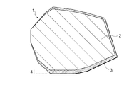
- FIG. 1 shows a schematic diagram of a main phase particle 1 of the present invention having a core portion 2 and a shell portion 3.
- the core portion 2 has a lower HR concentration than the shell portion 3.
- the maximum thickness 4 of the shell portion is the maximum thickness in the observed shell portion of the main phase particle 1.
- the x of the main phase LR (2-x) HR x T 14 B is increased in the vicinity of the interface between the main phase particle and the grain boundary phase, which is the starting point of reverse magnetic domain generation, and the main phase LR (2-x) HR x T
- the coercive force (HcJ) can be increased by increasing the anisotropic magnetic field of 14 B.
- the higher the HR content of the main phase the lower the saturation magnetization and the residual magnetic flux representing the magnetic strength of the magnet.
- the density (Br) also decreases. Therefore, Br can be kept high by reducing the HR in the core portion of the main phase particle having a small influence on HcJ and increasing the volume ratio of the core portion to the entire magnet.
- x of the main phase LR (2-x) HR x T 14 B of the core part of the main phase particle is 0.00 to 0.02
- HR is included in the core part including an error in analysis.
- Br can be made sufficiently high
- x of the main phase LR (2-x) HR x T 14 B of the shell part of the main phase particle is 0.20 to 0.40
- the shell part can be made to contain a lot of HR, and the improvement of HcJ can be increased.
- the grain boundary phase of the two-grain grain boundary exists between two adjacent main phase grains among the grain boundary phases, and is a phase having R and T as the main composition, and depending on the composition, has a needle shape or a plate shape.
- a region having a precipitate and having a width of about several nanometers is distinguished from the triple boundary of grain boundaries.
- the LR of the main phase LR (2-x) HR x T 14 B of the main phase particles is Nd or / and Pr, HR from the viewpoint of raw material costs and magnetic properties. Is preferably Dy or / and Tb.
- C is an element that substitutes a part of B in the main phase LR (2-x) HR x T 14 B of the main phase particles, but it easily forms carbides with the rare earth element, so that it is 500 to 2300 ppm. A range is desirable.
- the RTB-based sintered magnet of the present invention is preferably an HR prepared separately from the raw material alloy in one alloy method with one raw material alloy and two alloy methods with two raw material alloys.
- a compound powder containing a high melting point component is added to the finely pulverized powder of the raw material alloy to produce a compact, and the finely pulverized powder of the raw material alloy in the sintering step of the compact It can be obtained by performing a sintering process at a high temperature for a short time without cooling.
- the second alloy is preferably in the range of R: 29.0 to 60.0 mass%, T: 40.0 to 71.0 mass%, and is mixed with the first alloy including the main phase.
- the mixing ratio (first alloy / second alloy) is in the range of 0.97 / 0.03 to 0.70 / 0.30, from the viewpoint of obtaining high magnetic properties, from 0.95 / 0 ⁇ 05. 0.80 / 0.20 is preferable, and 0.95 / 0.05 to 0.85 / 0.25 is more preferable.
- the raw material alloy can be produced by ingot, strip casting, centrifugal casting or the like.
- the composition of the RTB-based sintered magnet of the present invention is as follows: LR is 29.4 to 31.5 mass%, HR is 0.15 to 0.65 mass%, Al Is 0.03 to 0.40 mass%, Co is 0.03 to 1.10 mass%, Cu is 0.03 to 0.18 mass%, B is 0.75 to 1.25 mass%, and the balance is Fe.
- Inevitable impurities are O: 0.03 to 0.12 mass%, N: 0.01 to 0.09 mass%, and C: 0.05 to 0.23 mass%.
- the particle size of the main phase particles is a fine sintered structure, the demagnetizing field of each main phase particle is reduced, the magnetization state is stabilized, and HcJ is improved.
- the most common method is to use finely pulverized powder with a reduced particle size.
- nitrogen is used as the pulverizing gas for the jet mill, R and nitrogen react in the process of finely pulverizing the coarsely pulverized powder, and the R-rich liquid phase component necessary for sintering may be insufficient.
- the pulverized particle size is 3 ⁇ m or more, preferably 4 ⁇ m or more.
- argon that does not react with R may be used as the pulverization gas.
- finely pulverized powder finely pulverized to an average particle size of less than 2 ⁇ m is used, a larger HcJ can be expected.
- argon is used as a pulverized gas, the pulverization efficiency is low, which is not preferable because the material yield decreases.
- helium is used as the pulverization gas, which is inert to the rare earth and has high pulverization efficiency. It is difficult to apply to mass production.
- the average particle size of the finely pulverized powder is suitably 8 ⁇ m or less. Therefore, the average particle size of finely pulverized powder considering the balance between magnetic characteristics and process cost in mass production is preferably 2 to 8 ⁇ m.
- Additive compound powder containing HR and coated with a high melting point component is added to the finely pulverized fine powder and mixed.
- a nauta mixer, a planetary mixer or the like can be used for mixing.
- the additive compound powder to be added must contain HR at 25.0 mass% or more. If the content of HR is less than 25.0 mass%, sufficient HcJ improvement effect cannot be obtained, or components that inhibit densification in sintering of RTB-based sintered magnets and magnetic characteristics In particular, the influence of a component that lowers HcJ becomes significant.
- the compound containing HR HR alone, halide, hydride, alloy, or the like can be used as the compound containing HR, HR alone, halide, hydride, alloy, or the like can be used.
- the high melting point component used for the coating layer needs a melting point that does not easily dissolve during sintering.
- a layer having low wettability with the R-rich liquid phase component generated during sintering is preferable because the reaction start of the additive compound can be easily controlled by the sintering temperature.
- the coating layer include boron carbide, boron nitride, silicon carbide, silicon nitride, aluminum nitride, titanium nitride, zirconium boride, hafnium boride, and tungsten carbide.
- a coating method suitable for the components of the coating layer to be used may be selected, such as PVD, CVD, vapor deposition, or formation on the surface of the HR compound using a chemical reaction.
- the thickness of the coating layer is not particularly limited, but the thickness is preferably such that it does not easily react and dissolve in sintering or remain unreacted.
- elements contained in the components of the coating layer carbon, nitrogen and the like are likely to be deteriorated in magnetic properties as impurities in the structure of the RTB-based sintered magnet, and if excessive boron is present, Fe 2 B is present at the grain boundary. For example, a soft magnetic phase or a non-magnetic phase is formed, leading to deterioration of magnetic properties. Therefore, it is preferable to avoid forming an excessively thick coating layer.
- the thickness of the coating layer is sufficient if a layer having a thickness of 100 nm to less than 1 ⁇ m can be formed, depending on the components used.
- the mixed powder of the raw material alloy is formed in a magnetic field.
- This forming in a magnetic field is carried out in an inert gas atmosphere such as nitrogen or argon with an oxygen concentration of less than 100 ppm to prevent oxidation of the finely pulverized powder of the raw material alloy.
- the orientation magnetic field may be 12 to 17 kOe (960 to 1360 kA / m), and the molding pressure may be about 0.7 to 2.0 tonf / cm 2 (70 to 200 MPa).
- the temperature in this high temperature process is a temperature range higher by 40 ° C. to 80 ° C. than the appropriate sintering temperature. It is preferable to do.
- the rate of temperature rise is preferably 8 to 20 ° C./min. If it is slower than this, diffusion of the additive compound powder into the main phase of HR may proceed excessively, and there is a possibility that the reduction of Br becomes remarkable.
- the maintenance time is preferably 60 minutes or less, and if it is longer than this, abnormal grain growth is promoted, and the HcJ decrease becomes remarkable.
- very fine main phase particles of sub-nano size are taken into large main phase particles by dissolution and re-precipitation.
- the average particle size of the main phase particles may be considered to be approximately the same as the average particle size of the finely pulverized powder used.
- an aging treatment is performed in which the obtained sintered body is heat-treated at a temperature lower than the sintering temperature.
- the aging treatment is performed in vacuum or in an inert gas atmosphere at 430 to 630 ° C. for about 30 to 180 minutes.
- the first stage is preferably higher in temperature than the second stage, and is performed at 650 to 950 ° C. for about 30 to 180 minutes in a vacuum or an inert gas atmosphere.
- the first stage is about 700 to 800 ° C. for about 60 minutes to 180 minutes, or 850 to 950 ° C. for 30 minutes to 50 minutes. It is preferable to carry out under conditions of about a minute.
- the RTB-based sintered magnet of the present invention is not limited to the method of adding an additive compound powder containing HR and coated with a high melting point component to the finely pulverized fine powder.
- it may be formed by a grain boundary diffusion method in which a powder containing HR is adhered to the film or a layer containing HR is formed and heat-treated.
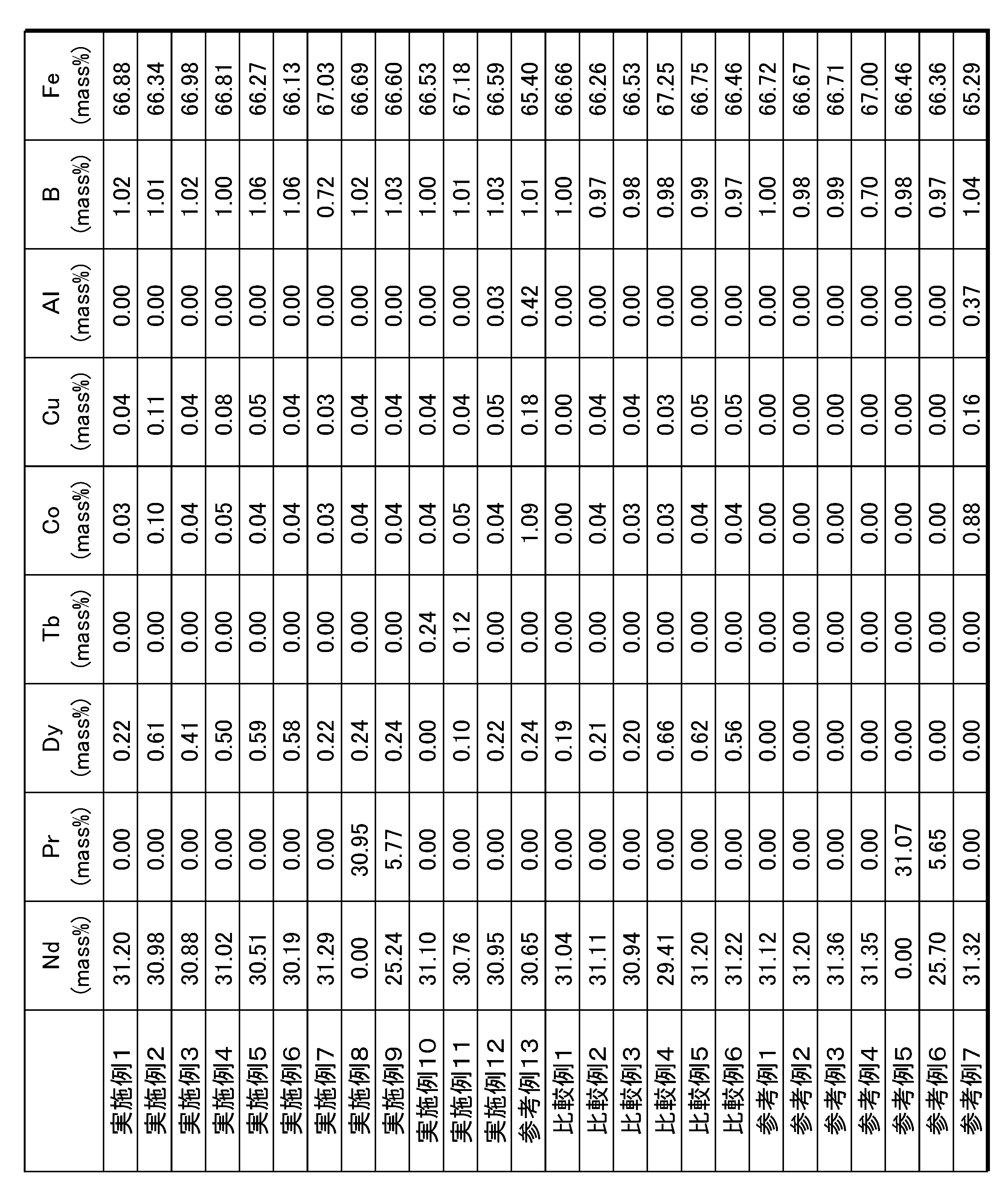
- Example 1 Raw material alloys having compositions A and D in Table 1 were produced by strip casting.
- the prepared raw material alloy A and raw material alloy D are mixed at a mixing ratio of 0.95 / 0.05, and after 90 minutes of hydrogen storage at room temperature, dehydrogenation treatment is performed at 650 ° C. for 60 minutes in an argon gas atmosphere. And coarsely pulverized. 0.10 mass% of oleic acid amide was added as a grinding aid to the coarsely pulverized powder of the raw material alloy. Thereafter, fine pulverization by a jet mill using high-pressure nitrogen gas was performed to obtain finely pulverized powder having an average particle size of 4.0 ⁇ m.
- An alloy compound containing Dy having a composition of G in Table 1 was melted at high frequency using an ingot matched with the composition of G, and the molten metal was made into a thin strip by roll quenching.
- Sputter while gently stirring the powder to be coated with vibration with the target being a cubic boron nitride (c-BN) plate on the surface as a powder with an average particle size of less than 10 ⁇ m by dry media grinding. Processing was performed to form a c-BN coating layer.
- the coated compound powder was added to the finely pulverized powder of the raw material alloy at 0.25 mass%, and mixed with a small Nauta mixer.
- the finely pulverized powder mixed with the compound powder was molded in a nitrogen gas atmosphere in a magnetic field of 15 kOe (1200 kA / m) at a pressure of 1.5 tonf / cm 2 (150 MPa) to obtain a molded body.
- the obtained molded body was first sintered at 1010 ° C. for 100 minutes in a reduced pressure atmosphere of 10 ⁇ 2 Pa or less, and the temperature was raised to 1070 ° C. at 10 ° C./min without interposing cooling. , Maintained for 20 minutes, and rapidly cooled by argon gas pressurization. Subsequently, the obtained sintered body was subjected to a heat treatment (first stage aging treatment) at 780 ° C./90 minutes in an atmospheric pressure argon gas atmosphere. After cooling, the sintered body was cooled to 540 ° C./hour in an atmospheric pressure argon gas atmosphere. A heat treatment (second stage aging treatment) for 90 minutes was performed to prepare an evaluation sample.
- the obtained evaluation sample was evaluated for magnetic properties by a BH tracer, and the structure was evaluated by STEM-EDS and atom probe analysis.
- the composition of the sintered body was analyzed and confirmed by fluorescent X-ray quantitative analysis.
- Example 2 A raw material alloy having a composition of A and D in Table 1 was finely pulverized in the same manner as in Example 1, and an alloy compound containing Dy having a composition of G in Table 1 was prepared in the same manner as in Example 1. Was added to the finely pulverized powder at 0.80 mass%, and an evaluation sample was prepared in the same manner as in Example 1.
- Example 4 The raw material alloy having the composition of B and D in Table 1 was finely pulverized in the same manner as in Example 1, and an alloy compound containing the composition of G in Table 1 was prepared in the same manner as in Example 1. It added to pulverized powder at 0.40 mass%, and the evaluation sample was produced similarly to Example 1.
- FIG. 4 The raw material alloy having the composition of B and D in Table 1 was finely pulverized in the same manner as in Example 1, and an alloy compound containing the composition of G in Table 1 was prepared in the same manner as in Example 1. It added to pulverized powder at 0.40 mass%, and the evaluation sample was produced similarly to Example 1.
- Example 5 The raw material alloys having the compositions of A and D in Table 1 were subjected to coarse pulverization in the same manner as in Example 1, 0.10 mass% of oleic acid amide was added as a pulverization aid, and the fineness was measured by a jet mill using high-pressure argon gas. Pulverization was performed to obtain finely pulverized powder having an average particle size of 2.0 ⁇ m.
- a compound of an alloy containing Dy having a composition of G in Table 1 was prepared in the same manner as in Example 1, added to the finely pulverized powder of the raw material alloy at 0.25 mass%, and mixed with a small Nauta mixer. Then, it was molded in a nitrogen gas atmosphere at a pressure of 1.5 tonf / cm 2 (150 MPa) in a magnetic field of 15 kOe (1200 kA / m) to obtain a molded body.
- the obtained molded body was first sintered at 940 ° C. for 100 minutes in a reduced pressure atmosphere of 10 ⁇ 2 Pa or less, and the temperature was raised to 980 ° C. at 8 ° C./min without interposing cooling. , Maintained for 20 minutes, and rapidly cooled by argon gas pressurization. Subsequently, the obtained sintered body was subjected to a heat treatment (first stage aging treatment) at 780 ° C./90 minutes in an atmospheric pressure argon gas atmosphere. After cooling, the sintered body was cooled to 540 ° C./hour in an atmospheric pressure argon gas atmosphere. A heat treatment (second stage aging treatment) for 90 minutes was performed to prepare an evaluation sample.
- Example 6 The raw material alloys having the compositions of A and D in Table 1 were subjected to coarse pulverization in the same manner as in Example 1, 0.10 mass% of oleic acid amide was added as a pulverization aid, and the fineness was measured by a jet mill using high-pressure argon gas. Pulverization was performed to obtain finely pulverized powder having an average particle size of 3.0 ⁇ m. Thereafter, an alloy compound containing Dy having a composition of G in Table 1 was prepared in the same manner as in Example 1, added to the finely pulverized powder of the raw material alloy at 0.25 mass%, and mixed with a small Nauta mixer. It was. Then, it was molded in a nitrogen gas atmosphere at a pressure of 1.5 tonf / cm 2 (150 MPa) in a magnetic field of 15 kOe (1200 kA / m) to obtain a molded body.
- Example 7 An evaluation sample was produced in the same manner as in Example 1 except that a raw material alloy having a composition of J and D in Table 1 was used.
- Example 8 An evaluation sample was prepared in the same manner as in Example 1 except that a raw material alloy having the composition of H and D in Table 1 was used.
- Example 9 An evaluation sample was prepared in the same manner as in Example 1 except that a raw material alloy having a composition of I and D in Table 1 was used.
- Example 10 The raw material alloy having the composition of A and D in Table 1 was finely pulverized in the same manner as in Example 1, and an alloy compound containing the composition of L in Table 1 was prepared in the same manner as in Example 1. It added to pulverized powder at 0.25 mass%, and the evaluation sample was produced similarly to Example 1.
- FIG. 10 The raw material alloy having the composition of A and D in Table 1 was finely pulverized in the same manner as in Example 1, and an alloy compound containing the composition of L in Table 1 was prepared in the same manner as in Example 1. It added to pulverized powder at 0.25 mass%, and the evaluation sample was produced similarly to Example 1.
- Example 11 The raw material alloy having the composition of A and D in Table 1 is finely pulverized in the same manner as in Example 1, and an alloy compound containing the composition of M in Table 1 is prepared in the same manner as in Example 1. It added to pulverized powder at 0.25 mass%, and the evaluation sample was produced similarly to Example 1.
- FIG. 11 The raw material alloy having the composition of A and D in Table 1 is finely pulverized in the same manner as in Example 1, and an alloy compound containing the composition of M in Table 1 is prepared in the same manner as in Example 1. It added to pulverized powder at 0.25 mass%, and the evaluation sample was produced similarly to Example 1.
- Example 12 The raw material alloy having the composition of A and D in Table 1 was finely pulverized in the same manner as in Example 1, and an alloy compound containing the composition of N in Table 1 was prepared in the same manner as in Example 1. It added to pulverized powder at 0.30 mass%, and the evaluation sample was produced similarly to Example 1.
- FIG. 12 The raw material alloy having the composition of A and D in Table 1 was finely pulverized in the same manner as in Example 1, and an alloy compound containing the composition of N in Table 1 was prepared in the same manner as in Example 1. It added to pulverized powder at 0.30 mass%, and the evaluation sample was produced similarly to Example 1.
- Example 13> The raw material alloy having the composition of A and F in Table 1 was finely pulverized in the same manner as in Example 1, and an alloy compound containing the composition of G in Table 1 was prepared in the same manner as in Example 1. It added to pulverized powder at 0.25 mass%, and the evaluation sample was produced similarly to Example 1.
- FIG. ⁇ Comparative Example 1> The raw material alloys having the compositions of B and D in Table 1 were subjected to pulverization in the same manner as in Example 1 and evaluated in the same manner as in Example 1 without adding an alloy compound containing Dy having the composition of G in Table 1. A sample was prepared.
- Example 2 The raw material alloys having the compositions A and D in Table 1 were subjected to fine pulverization in the same manner as in Example 1. After the compound of the alloy containing Dy having the G composition in Table 1 was pulverized in the same manner as in Example 1, c- A BN coating was not formed, but was added to the finely pulverized powder of the raw material alloy at 0.25 mass%, and mixing was performed using a small Nauta mixer. The obtained mixed powder produced an evaluation sample in the same manner as in Example 1.
- Example 5 The raw material alloys having the compositions A and D in Table 1 were subjected to fine pulverization in the same manner as in Example 5. After pulverizing the alloy compound containing Dy having the G composition in Table 1 in the same manner as in Example 5, c- A BN coating was not formed, but was added to the finely pulverized powder of the raw material alloy at 0.25 mass%, and mixing was performed using a small Nauta mixer. The obtained mixed powder produced an evaluation sample in the same manner as in Example 5.
- Example 6 The raw material alloys having the compositions A and D in Table 1 were subjected to fine pulverization in the same manner as in Example 6, and the alloy compound containing Dy having the G composition in Table 1 was pulverized in the same manner as in Example 6. A BN coating was not formed, but was added to the finely pulverized powder of the raw material alloy at 0.25 mass%, and mixing was performed using a small Nauta mixer. The obtained mixed powder produced an evaluation sample in the same manner as in Example 6.
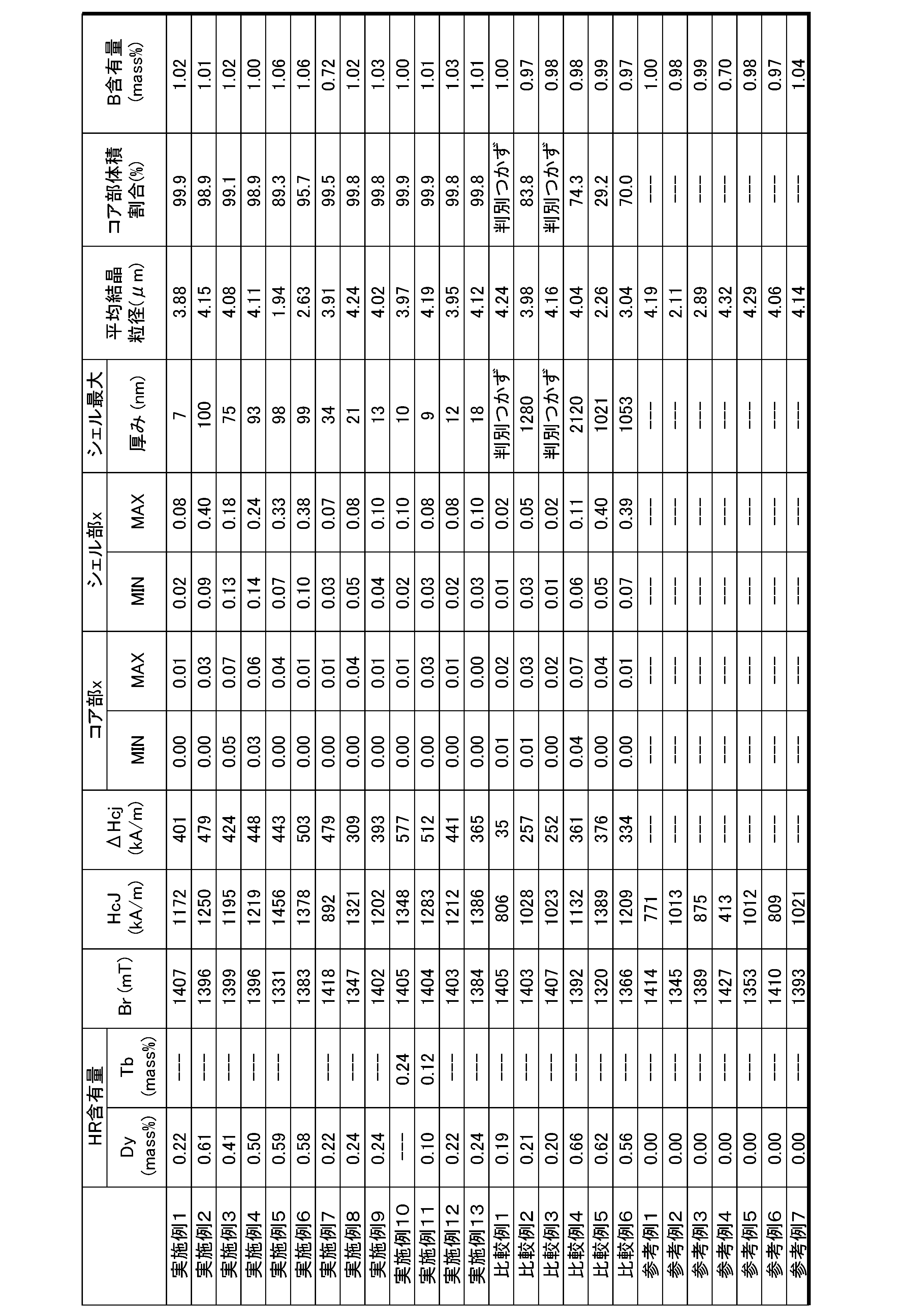
- Example 1 and Example 2 have significantly improved HcJ over Comparative Example 1 and Comparative Example 4 each containing substantially the same amount of Dy. That is, the Dy content required for obtaining the same HcJ can be greatly reduced according to the present invention.
- 2 and FIG. 3 are HcJ and Br when no additive compound is added to the finely pulverized powder of the raw material alloy of Example 1.
- Comparative Example 2 the same amount as in Example 1 was added to the finely pulverized powder of the raw material alloy without forming the c-BN coating in the additive compound powder having the composition of G in Table 1. Comparative Example 1 Higher HcJ is obtained. However, it was 144 kA / m lower than HcJ of Example 1 and the c-BN coating layer was not formed on the surface of the additive compound powder, so that the additive compound easily reacted with the R-rich liquid phase during the sintering process. Dy substitution proceeds deeply into the core portion of the main phase particle, and the effects of the present invention are not sufficiently obtained.
- Example 1 has almost the same Br as that of Comparative Example 1 containing substantially the same amount Dy, and Example 2 also has almost the same amount of Comparative Example 4 containing almost the same amount Dy. It is shown that HcJ is greatly improved while maintaining Br according to the present invention.
- HcJ is 149 kA / m larger and Br is substantially equivalent to Comparative Example 3 in which substantially the same amount of Dy and approximately the same amounts of Co and Cu are added.
- HcJ can be improved by additive elements such as Co and Cu, it has been shown that the improvement of HcJ according to the present invention is remarkable even if the HcJ improvement by Co and Cu is subtracted.
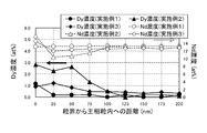
- FIG. 4 shows quantitative amounts of Dy and Nd in the direction from the two-particle grain boundary to the main phase particle by STEM-EDS in Example 1, Example 2, and Example 3, and shows the main phase from the grain boundary interface.
- the largest Dy substitution range within the particles is confirmed to be about 100 nm in Example 2, the Dy concentration is also the highest, and the Dy substitution range and its concentration are increased by the addition amount of the added compound. Indicates.
- the Dy substitution range of Example 3 is approximately 75 nm, but the Dy concentration is smaller than Example 2. This seems to indicate that Dy substitution in the main phase is suppressed by the presence of Dy in the main phase particles in advance.
- Comparative Example 1 Comparative Example 2, Comparative Example 3 and Comparative Example 4, the concentration distributions of Dy and Nd in the direction from the two-grain boundary to the main phase particle by STEM-EDS were examined. In Comparative Example 3, the clear concentration difference of Dy could not be confirmed as the Dy substitution range was clearly divided. In Comparative Example 2, although the Dy concentration difference was small but the Dy replacement range could be determined, the maximum width was 1280 nm, which is considerably wider than that of the example. Similarly, the Dy substitution range could also be determined in Comparative Example 4, but the maximum width was 2120 nm, which was found to be wider than that of Comparative Example 2.
- Example 2 when the Dy replacement range of Example 2 and Example 3 is taken as the maximum shell portion width, and the minimum value to the maximum value of x in the maximum shell portion width are estimated, 0.09 is obtained in Example 2. It was ⁇ 0.40, and in Example 3, it was 0.13 to 0.18. Further, when the core portion is a range where the Nd concentration distribution is almost constant compared to the shell portion, and the minimum value to the maximum value of x in the core portion are estimated, 0.03 in Example 3, 0.05 to 0.07.
- Comparative Example 1 Comparative Example 2, Comparative Example 3 and Comparative Example 4, as in Example 2 and Example 3, the minimum and maximum values of x in the shell portion and the core portion were estimated.
- the shell portion was not clearly discriminated. Therefore, assuming that the shell portion was 1000 nm, the minimum value to the maximum value of x of the shell portion and the core portion were estimated.
- the minimum value to the maximum value of x of the shell part are 0.01 to 0.02 in Comparative Example 1, 0.03 to 0.05 in Comparative Example 2, 0.01 to 0.02 in Comparative Example 3, and Comparative Example 4 became 0.06 to 0.11.
- the minimum value to the maximum value of x of the core portion are 0.01 to 0.02 in Comparative Example 1, 0.01 to 0.03 in Comparative Example 2, 0.00 to 0.02 in Comparative Example 3, and Example 4 was 0.04 to 0.007.
- Example 1 Dy has a high concentration at the grain boundary, but STEM-EDS has not yet clarified the Dy substitution range in the main phase particles. Therefore, an atom probe analysis that can be quantified with higher resolution was performed. As for other examples, atom probe analysis was performed for the case where the Dy substitution range could not be clarified by STEM-EDS.
- FIG. 5 shows the quantitative values of Dy and Nd in the vicinity of the two-particle grain boundary by the atom probe analysis of Example 1.
- the Dy concentration becomes maximum at the interface between the main phase particle and the grain boundary phase, and the higher the Dy concentration is. Since the Nd concentration is reduced, it is shown that the Dy substitution range in the main phase particles is 7 nm at the minimum.
- the reason why HcJ is improved by Dy substitution is that nucleation of reverse magnetic domains is suppressed by an anisotropic magnetic field having high Dy, but the effect is also achieved in the Dy substitution range of 7 nm in Example 1. High HcJ is obtained by acting greatly.
- the Dy replacement range confirmed by the atom probe analysis is taken as the maximum shell portion width, and the minimum value to the maximum value of x in the maximum shell portion width are estimated.
- the core portion is a range where the Nd concentration distribution is substantially constant compared to the shell portion, and the minimum value to the maximum value of x in the core portion are estimated, 0.01.
- the particle size of the finely pulverized powder is about 2 ⁇ m and about 3 ⁇ m, respectively, and the finely pulverized powder is made finer than in Example 4, and an alloy containing Dy is added thereto as in Example 4. is doing.
- the main phase particle diameter in the fine sintered structure is almost similar to that, and the maximum thickness of the shell portion of the main phase particles is almost the same. Therefore, in the finer example 5, the core portion volume ratio of the main phase particles is smaller, and Br is low as the magnetic properties, but HcJ is greatly improved, and the effect of the invention appears. .
- Comparative Example 5 and Comparative Example 6 since the c-BN coating was not applied to the finely pulverized powder of the alloy containing Dy added in Example 5 and Example 6, A large amount of Dy is taken in to form a thick shell portion, and Br is greatly reduced as compared with the case where the material is made of only the raw material alloy, but HcJ is not improved as much as Example 5 and Example 6.
- Example 5 although it is not a big problem as a magnetic characteristic, the fall of Br is a little large compared with the case of only a raw material alloy, and in order to improve HcJ while maintaining Br high enough, it is a main phase.
- the core volume ratio of the particles is preferably 90% or more.
- Example 7 the B content was reduced to 0.72, and the HcJ was as small as 892 kA / m. This is because the HcJ when made of only the raw material alloy was as small as 413 kA / m. The addition of an alloy containing is improved by 479 kA / m, and the effect of the present invention is obtained.
- the original HcJ based only on the raw material alloy is also necessary to some extent, and reducing the B content too much as in Example 7 forms a soft magnetic phase containing Fe. Since it leads to HcJ becoming low, it is preferable that B content shall be 0.75 mass% or more.
- Example 8 the sample was prepared using all the Nd of the raw material alloy of Example 1, and in Example 9, the raw material alloy in which a part of Nd was replaced with Pr was used, but only Nd was used.
- the effect by this invention is acquired similarly to Example 1.
- Example 10 samples were prepared using all of Dy of the alloy containing Dy used in Example 1, and in Example 11, an alloy in which half was substituted with Tb. HcJ is greatly improved over the addition of. This is because, when LR such as Nd constituting the main phase is replaced with Tb, the anisotropic magnetic field that greatly affects HcJ is larger than when it is replaced with Dy.
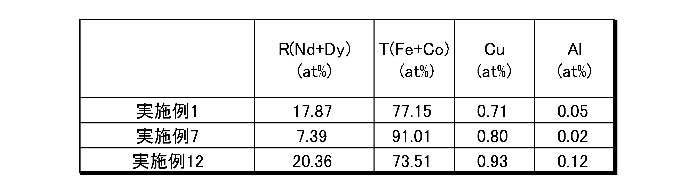
- Table 4 shows the content ratios of R amount (Nd + Dy), T amount (Fe + Co), Cu, and Al at the grain boundary of Example 1, Example 7, and Example 12.
- Example 12 a sample was prepared using an alloy in which a part of Dy of the alloy containing Dy used in Example 1 was replaced with Al. However, HcJ was greatly improved as compared with Example 1. Yes. From the atom probe analysis, in the grain boundary phase of the two-grain grain boundary of Example 12, the R amount combining Nd and Dy is 20.36 at%, the T amount combining Fe and Co is 73.51 at%, and Cu is 0.00. 93 at% and Al were 0.12 at%.
- Example 1 in which Al was not included in the alloy containing Dy, the rare earth combined with Nd and Dy was 17.87 at%, the T amount combined with Fe and Co was 77.15 at%, and Cu was 0. .71 at% and Al was 0.05 at%. From this, it can be considered that the improvement in HcJ in Example 12 was greater than that in Example 1 because Al that was effective in improving HcJ was added and existed at the grain boundary.
- Example 7 when an atom probe analysis of the two-grain grain boundary was performed on Example 7, the R amount combining Nd and Dy was 7.39 at%, the T amount combining Fe and Co was 91.01 at%, and Cu was 0 .80 at%, Al is 0.02 at%, the R amount is small, and the T amount is large. From this, in Example 7, the B content was excessively reduced, so that an excess of Fe or Co not forming the main phase was formed, and R and a soft magnetic phase were formed in the grain boundary phase, and the original HcJ Is considered to be a small result. However, also in Example 7, the effect of improving HcJ by the present invention appears.
- R (where R is one or more of Y (yttrium) and rare earth elements) is 10 to 30 at% at the two-grain boundary of the sintered body, and T (Fe Or one or more transition metals essentially containing Fe and Co) is 65 to 85 at%, Cu is 0.70 to 4.0 at%, Al is 0.07 to 2.0 at%, Preferably there is.
- Reference Example 7 has a larger amount of Co, Cu, and Al added from the raw material alloy than Comparative Examples 3 and 4, and the composition and structure are substantially the same except that Co, Cu, and Al are not included.
- HcJ is high.
- Example 13 in which an alloy having the composition of G in Table 1 was added to Reference Example 7, HcJ was improved while suppressing a decrease in Br as in the other Examples, but G in Table 1 was added to Reference Example 1.
- the improvement of HcJ as great as that of Example 1 to which an alloy having the composition was added was not obtained. The reason why the improvement in HcJ is slightly small in Example 13 cannot be determined.
- the improvement of HcJ by Dy is much more effective than simply including Dy from the raw material alloy, and is a sufficiently practical technique. From this, the upper limit of the contents of Co, Cu, and Al is 1.10 mass% for Co, 0.18 mass% for Cu, and 0.40 mass% for Al.
- an RTB-based sintered magnet having a significantly improved HcJ can be obtained with a small Dy content, and further, when maintaining the conventional magnetic properties, the Dy content is greatly reduced.
- an RTB-based sintered magnet can be obtained.
- the present invention can provide an RTB-based sintered magnet in which the amount of heavy rare earth elements is reduced while maintaining high magnetic properties.
Landscapes
- Chemical & Material Sciences (AREA)
- Engineering & Computer Science (AREA)
- Materials Engineering (AREA)
- Mechanical Engineering (AREA)
- Metallurgy (AREA)
- Organic Chemistry (AREA)
- Power Engineering (AREA)
- Crystallography & Structural Chemistry (AREA)
- Inorganic Chemistry (AREA)
- Hard Magnetic Materials (AREA)
- Powder Metallurgy (AREA)
Abstract
Description
好ましくは、前記主相粒子の2粒子粒界の粒界相において、R(RはY(イットリウム)および希土類元素の1種又は2種以上)が10~30at%であり、T(Fe又はFe及びCoを必須とする1種又は2種以上の遷移金属)が65~85at%であって、Cuが0.70~4.0at%、Alが0.07~2.0at%、である。
また、より好ましくは、前記LRはNdまたは/およびPrであり、HRはDyまたは/およびTbである。
また、より好ましくは、前記主相粒子全体に占めるコア部の体積比率が90.0%以上である。
また、より好ましくは前記R-T-B系焼結磁石の組成は、LRが29.4~31.5mass%、HRが0.15~0.65mass%、Alが0.03~0.40mass%、Coが0.03~1.10mass%、Cuが0.03~0.18mass%、Bが0.75~1.25mass%、残部がFeである。
本発明のR-T-B系焼結磁石は、主相LR(2-x)HRxT14B(LR:Ndを必須とし、Y、La、Ce、Pr、Smの1種または2種以上を含む軽希土類元素、HR:Dyまたは/およびTbを必須とし、Gd、Ho、Er、Tm、Yb,Luの1種または2種以上を含む重希土類元素、T:Feまたは/およびCoを必須とし、Mn、Niの1種または2種を含む、B:(ホウ素、一部C(炭素)で置換されているものを含む))を主相とする主相粒子と、R(RはY(イットリウム)および希土類元素の1種又は2種以上)、およびT(TはFe又はFe及びCoを必須とする1種又は2種以上)を主組成とする粒界相とから構成される。さらに、主相粒子は、主相LR(2-x)HRxT14Bがx=0.00~0.07の範囲であるコア部と、主相LR(2-x)HRxT14Bがx=0.02~0.40の範囲であるシェル部から形成された構造をもつ。
図1はコア部2とシェル部3をもつ本発明の主相粒子1の模式図を示している。このコア部2はシェル部3に比べHR濃度が低い。シェル部の最大厚み4は、観察した主相粒子1のシェル部において最大の厚みをとる。
本発明のR-T-B系焼結磁石において、主相粒子のコア部の主相LR(2-x)HRxT14Bのxは、好ましくは、0.00~0.02であり、主相粒子のシェル部の主相LR(2-x)HRxT14Bのxは、好ましくは0.20~0.40の範囲である。本発明のR-T-B系焼結磁石において、主相粒子のコア部のHR量を少なくすることでBrを高く維持でき、シェル部のHR量を多くすることでHcJを大きく向上することができるが、主相粒子のコア部の主相LR(2-x)HRxT14Bのxが0.00~0.02であると、解析の誤差を含めて、コア部にHRが含まれておらず、Brを十分に高くすることができ、主相粒子のシェル部の主相LR(2-x)HRxT14Bのxが0.20~0.40であると、シェル部にHRを多く含ませた状態にでき、HcJの向上が大きくできる。
前記2粒子粒界の粒界相は、粒界相のうち、隣り合う2つの主相粒子の間に存在し、RならびにTを主組成とする相、および組成によっては針状や板状の析出物を有する、幅数nm程度の領域で、粒界3重点とは区別される。
本発明のR-T-B系焼結磁石は、好適には原料合金が1種類の1合金法、および原料合金が2種類の2合金法において、前記原料合金とは別に準備された、HRを含有し、表面を高融点成分によりコーティングされた化合物粉を、原料合金の微粉砕粉にごく少量添加して成形体を作製し、前記成形体の焼結工程において、原料合金の微粉砕粉のみでの焼結に対し、高温でごく短時間の焼結過程を、冷却を挟まずに行うことで得られる。
添加する添加化合物粉は、HRを25.0mass%以上で含有することが必須とする。HRの含有量が25.0mass%よりも少な過ぎると、十分なHcJ向上の効果が得られなかったり、R-T-B系焼結磁石の焼結において緻密化を阻害する成分や、磁気特性、特にHcJを低下させる成分の影響が顕著になる。HRを含有する化合物として、HR単体、ハロゲン化物、水素化物、合金などが利用できる。
コーティング層に使用する高融点成分としては、焼結において容易に溶解しない程度の融点が必要となる。また、焼結中に発生するRリッチな液相成分との濡れ性が低い層であれば、添加化合物の反応開始を焼結温度により制御し易くなるので好ましい。コーティング層の例としては、炭化ホウ素、窒化ホウ素、炭化ケイ素、窒化ケイ素、窒化アルミニウム、窒化チタン、ホウ化ジルコニウム、ホウ化ハフニウム、炭化タングステンなどがある。コーティングの方法としてはPVD、CVD、蒸着法、HR化合物表面に化学反応を利用して形成するなど、使用するコーティング層の成分に適したコーティング方法を選択すればよい。
また、コーティング層の厚みに特に制限はないが、焼結において容易に反応して溶解したり、あるいは反応し切らないまま残ることがない程度の厚みがよい。コーティング層の成分に含まれる元素について、炭素、窒素などはR-T-B系焼結磁石の組織においては不純物として磁気特性の低下につながりやすく、ホウ素も過剰に存在すると粒界にFe2Bなど軟磁性相あるいは非磁性相を形成して磁気特性の低下につながる。そのため、過剰に厚いコーティング層を形成することは避けることが好ましい。使用する成分により変わるが、コーティング層の厚みとしては100nm~1μm未満の層が形成できれば十分である。
この高温過程により、前記適正な焼結温度では反応が抑制されていた高融点成分にコーティングされた添加化合物粉と、Rリッチな液相成分との反応を促進させ、主相粒子の粒界近傍で主相のLRをHRで置換させる。この高温過程の温度は、多数の成形体を焼結する場合の均熱と添加化合物粉からのHR放出のバランスを考慮し、前記適正な焼結温度に対し40℃~80℃高い温度範囲とすることが好ましい。
昇温速度は8~20℃/分が好ましく、これより遅い場合は添加化合物粉のHRの主相内への拡散が進行し過ぎてBr低下が顕著になる恐れがある。また、昇温速度がこれより速い場合は、均熱がとりにくくなって、磁石表面での異常粒成長が急速に促進され、1つの焼結体内および焼結炉内の位置が異なる焼結体でHcJのばらつきが無視できなくなり、磁気特性および生産安定性を悪化させる恐れがある。また、維持時間は60分以下が好ましく、これより長時間となると異常粒成長が促進してHcJ低下が顕著となる。焼結過程でサブナノサイズのきわめて微細な主相粒子が溶解-再析出によって大きな主相粒子に取り込まれて無くなるが、ジェットミルで粉砕した微粉砕粉の粒度分布では少ない存在量なので、過剰な粒成長が起きない適切な焼結条件で作製した焼結体では主相粒子の平均粒径は使用した微粉砕粉の平均粒径とほぼ同じ大きさと考えてよい。
表1のAとDの組成の原料合金を、ストリップキャストにて作製した。
作製した原料合金Aと原料合金Dを混合比0.95/0.05で混合し、室温にて90分間の水素吸蔵をさせた後、アルゴンガス雰囲気中で650℃×60分の脱水素処理を施して粗粉砕を行った。
原料合金の粗粉砕粉に粉砕助剤としてオレイン酸アミドを0.10mass%添加した。その後、高圧窒素ガスを用いたジェットミルによる微粉砕を行い、平均粒径4.0μmの微粉砕粉を得た。

前記コーティングした化合物粉を、前記原料合金の微粉砕粉へ0.25mass%で添加し、小型のナウタミキサーにて混合を行った。
次に、化合物粉と混合した微粉砕粉を、窒素ガス雰囲気中にて、15kOe(1200kA/m)の磁場中で1.5tonf/cm2(150MPa)の圧力で成形して成形体を得た。
続いて、得られた焼結体を、大気圧アルゴンガス雰囲気中にて780℃/90分の熱処理(1段目時効処理)を行い、冷却後、大気圧アルゴンガス雰囲気中にて540℃/90分の熱処理(2段目時効処理)を行い、評価試料を作製した。
表1のAとDの組成の原料合金を、実施例1と同様に微粉砕まで行い、表1のGの組成のDyを含む合金の化合物を、実施例1と同様に準備し、原料合金の微粉砕粉へ0.80mass%で添加し、実施例1と同様に評価試料を作製した。
表1のBとDの組成の原料合金を用いることを除き、実施例1と同様に評価試料を作製した。
表1のBとDの組成の原料合金を、実施例1と同様に微粉砕まで行い、表1のGの組成を含む合金の化合物を、実施例1と同様に準備し、原料合金の微粉砕粉へ0.40mass%で添加し、実施例1と同様に評価試料を作製した。
表1のAとDの組成の原料合金を、実施例1と同様に粗粉砕まで行い、粉砕助剤としてオレイン酸アミドを0.10mass%添加して、高圧アルゴンガスを用いたジェットミルによる微粉砕を行い、平均粒径2.0μmの微粉砕粉を得た。
続いて、得られた焼結体を、大気圧アルゴンガス雰囲気中にて780℃/90分の熱処理(1段目時効処理)を行い、冷却後、大気圧アルゴンガス雰囲気中にて540℃/90分の熱処理(2段目時効処理)を行い、評価試料を作製した。
表1のAとDの組成の原料合金を、実施例1と同様に粗粉砕まで行い、砕助剤としてオレイン酸アミドを0.10mass%添加して、高圧アルゴンガスを用いたジェットミルによる微粉砕を行い、平均粒径3.0μmの微粉砕粉を得た。その後、表1のGの組成のDyを含む合金の化合物を、実施例1と同様に準備し、原料合金の微粉砕粉へ0.25mass%で添加し、小型のナウタミキサーにて混合を行った。その後、窒素ガス雰囲気中にて、15kOe(1200kA/m)の磁場中で1.5tonf/cm2(150MPa)の圧力で成形して成形体を得た。
続いて、得られた焼結体を、大気圧アルゴンガス雰囲気中にて780℃/90分の熱処理(1段目時効処理)を行い、冷却後、大気圧アルゴンガス雰囲気中にて540℃/90分の熱処理(2段目時効処理)を行い、評価試料を作製した。
表1のJとDの組成の原料合金を用いることを除き、実施例1と同様に評価試料を作製した。
表1のHとDの組成の原料合金を用いることを除き、実施例1と同様に評価試料を作製した。
表1のIとDの組成の原料合金を用いることを除き、実施例1と同様に評価試料を作製した。
表1のAとDの組成の原料合金を、実施例1と同様に微粉砕まで行い、表1のLの組成を含む合金の化合物を、実施例1と同様に準備し、原料合金の微粉砕粉へ0.25mass%で添加し、実施例1と同様に評価試料を作製した。
表1のAとDの組成の原料合金を、実施例1と同様に微粉砕まで行い、表1のMの組成を含む合金の化合物を、実施例1と同様に準備し、原料合金の微粉砕粉へ0.25mass%で添加し、実施例1と同様に評価試料を作製した。
表1のAとDの組成の原料合金を、実施例1と同様に微粉砕まで行い、表1のNの組成を含む合金の化合物を、実施例1と同様に準備し、原料合金の微粉砕粉へ0.30mass%で添加し、実施例1と同様に評価試料を作製した。
表1のAとFの組成の原料合金を、実施例1と同様に微粉砕まで行い、表1のGの組成を含む合金の化合物を、実施例1と同様に準備し、原料合金の微粉砕粉へ0.25mass%で添加し、実施例1と同様に評価試料を作製した。
<比較例1>
表1のBとDの組成の原料合金を、実施例1と同様に微粉砕まで行い、表1のGの組成のDyを含む合金の化合物を添加せずに、実施例1と同様に評価試料を作製した。
表1のAとDの組成の原料合金を、実施例1と同様に微粉砕まで行い、表1のGの組成のDyを含む合金の化合物を実施例1と同様に粉砕した後、c-BNのコーティングは形成せずに、前記原料合金の微粉砕粉へ0.25mass%で添加し、小型のナウタミキサーにて混合を行った。得られた混合粉は、実施例1と同様に評価試料を作製した。
表1のBとEの組成の原料合金を、実施例1と同様に微粉砕まで行い、表1のGの組成のDyを含む合金の化合物を添加せずに、実施例1と同様に評価試料を作製した。
表1のCとEの組成の原料合金を、実施例1と同様に微粉砕まで行い、表1のGの組成のDyを含む合金の化合物を添加せずに、実施例1と同様に評価試料を作製した。
表1のAとDの組成の原料合金を、実施例5と同様に微粉砕まで行い、表1のGの組成のDyを含む合金の化合物を実施例5と同様に粉砕した後、c-BNのコーティングは形成せずに、前記原料合金の微粉砕粉へ0.25mass%で添加し、小型のナウタミキサーにて混合を行った。得られた混合粉は、実施例5と同様に評価試料を作製した。
表1のAとDの組成の原料合金を、実施例6と同様に微粉砕まで行い、表1のGの組成のDyを含む合金の化合物を実施例6と同様に粉砕した後、c-BNのコーティングは形成せずに、前記原料合金の微粉砕粉へ0.25mass%で添加し、小型のナウタミキサーにて混合を行った。得られた混合粉は、実施例6と同様に評価試料を作製した。
また、実施例1~3および比較例1~4のHcJをDy含有量に対する変化として図2に、実施例1~3および比較例1~4のBrをDy含有量に対する変化として図3に示した。
実施例3のDy置換範囲は、およそ75nmであるが、Dy濃度は実施例2より小さい。これは、主相粒子内にあらかじめDyが存在することで、主相のDy置換が抑制されていることを示すと思われる。
また、Ndの濃度分布が、シェル部に比べほぼ一定となっている範囲をコア部ととり、そのコア部の中でxの最小値~最大値を見積もると、実施例2では0.00~0.03、実施例3では0.05~0.07であった。
シェル部のxの最小値~最大値は、比較例1が0.01~0.02、比較例2が0.03~0.05、比較例3が0.01~0.02、比較例4が0.06~0.11となった。またコア部のxの最小値~最大値は、比較例1が0.01~0.02、比較例2が0.01~0.03、比較例3が0.00~0.02、比較例4が0.04~0.0.07となった。
Dy置換によりHcJが向上されるのは、Dyの高い異方性磁界によって逆磁区の核形成が抑制されるためであるとされるが、実施例1における7nmのDy置換範囲でも、その効果が大きく作用して高いHcJが得られている。
一方、比較例5および比較例6は、実施例5および実施例6で添加したDyを含有する合金の微粉砕粉にc-BNコーティングを施していないため、焼結過程において主相粒子中にDyが多量に取り込まれて厚いシェル部が形成されており、原料合金のみより作製した場合よりBrが大きく低下しているが、HcJが実施例5および実施例6ほど大きくは向上していない。
しかしながら、実施例5において、磁気特性としては大きな問題ではないが、原料合金のみの場合に対しBrの低下がやや大きくなっており、Brも十分に高く維持しながらHcJを向上させる上では主相粒子のコア部体積割合を90%以上とすることが好ましい。
しかしながら、製品として適するHcJを得る上では原料合金のみによるもともとのHcJもある程度必要であるといえ、実施例7のようにB含有量を少なくし過ぎることはFeを含む軟磁性相を形成してHcJが低くなることにつながるため、B含有量は0.75mass%以上とすることが好ましい。
また、実施例7について2粒子粒界のアトムプローブ解析を行ったところ、NdとDyを合わせたR量が7.39at%、FeとCoを合わせたT量が91.01at%、Cuが0.80at%、Alが0.02at%で、R量が少なくなり、T量が多く存在している。このことから、実施例7ではB含有量を過剰に少なくしているため主相を組まないFeやCoの余剰ができて粒界相においてRと軟磁性相を形成してしまい、もともとのHcJが小さい結果となっていると考えられる。ただ、実施例7においても本発明によるHcJ向上の効果は現れている。
したがって、製品として適するHcJを得る上で、焼結体の2粒子粒界においてR(RはY(イットリウム)および希土類元素の1種又は2種以上)が10~30at%であり、T(Fe又はFe及びCoを必須とする1種又は2種以上の遷移金属)が65~85at%であって、Cuが0.70~4.0at%、Alが0.07~2.0at%、であることが好ましい。
いずれにせよ、多量のCo、Cu、AlによるHcJの向上を完全に残しながらDyによるHcJのさらなる向上を実現するのは難しい。しかし、DyによるHcJの向上は原料合金からDyを単純に含有させるよりもずっと大きな効果が得られており、十分に実用可能な手法である。このことから、Co、Cu、Alの含有量の上限については、Coが1.10mass%、Cuが0.18mass%、Alが0.40mass%である。
2 コア部
3 シェル部
4 シェル部の最大厚み
Claims (5)
- R-T-B系焼結磁石であって、主相粒子と粒界相を有し、前記主相粒子は、コア部とシェル部を含み、前記コア部の主相LR(2-x)HRxT14B(LR:Ndを必須とし、Y、La、Ce、Pr、Smの1種または2種以上を含む軽希土類元素、HR:Dyまたは/およびTbを必須とし、Gd、Ho、Er、Tm、Yb,Luの1種または2種以上を含む重希土類元素、T:Feまたは/およびCoを必須とし、Mn、Niの1種または2種を含む、B:(ホウ素、一部C(炭素)で置換されているものを含む)においてx=0.00~0.07であり、前記シェル部の主相LR(2-x)HRxT14Bにおいてx=0.02~0.40であり、かつ前記シェル部の最大厚みが、7nm~100nmであることを特徴とするR-T-B系焼結磁石。
- 請求項1記載のR-T-B系焼結磁石であって、前記主相粒子の2粒子粒界の粒界相において、R(RはY(イットリウム)および希土類元素の1種又は2種以上)が10~30at%であり、T(Fe又はFe及びCoを必須とする1種又は2種以上の遷移金属)が65~85at%であって、Cuが0.70~4.0at%、Alが0.07~2.0at%、であることを特徴とするR-T-B系焼結磁石。
- 請求項1記載のR-T-B系焼結磁石であって、前記LRはNdまたは/およびPrであり、HRはDyまたは/およびTbであることを特徴とするR-T-B系焼結磁石。
- 請求項1乃至請求項2記載のR-T-B系焼結磁石であって、前記主相粒子全体に占めるコア部の体積比率が、90.0%以上であることを特徴とするR-T-B系焼結磁石。
- 請求項1乃至請求項4のR-T-B系焼結磁石であって、組成がLRが29.4~31.5mass%、HRが0.15~0.65mass%、Alが0.03~0.40mass%、Coが0.03~1.10mass%、Cuが0.03~0.18mass%、Bが0.75~1.25mass%、残部がFeであることを特徴とするR-T-B系焼結磁石。
Priority Applications (3)
| Application Number | Priority Date | Filing Date | Title |
|---|---|---|---|
| US14/354,865 US9548148B2 (en) | 2011-10-28 | 2012-10-04 | R-T-B based sintered magnet |
| CN201280053073.6A CN103890868B (zh) | 2011-10-28 | 2012-10-04 | R‑t‑b系烧结磁铁 |
| DE112012004502.5T DE112012004502T5 (de) | 2011-10-28 | 2012-10-04 | R-T-B basierter gesinterter Magnet |
Applications Claiming Priority (4)
| Application Number | Priority Date | Filing Date | Title |
|---|---|---|---|
| JP2011236617 | 2011-10-28 | ||
| JP2011-236617 | 2011-10-28 | ||
| JP2012-212333 | 2012-09-26 | ||
| JP2012212333A JP6089535B2 (ja) | 2011-10-28 | 2012-09-26 | R−t−b系焼結磁石 |
Publications (1)
| Publication Number | Publication Date |
|---|---|
| WO2013061744A1 true WO2013061744A1 (ja) | 2013-05-02 |
Family
ID=48167579
Family Applications (1)
| Application Number | Title | Priority Date | Filing Date |
|---|---|---|---|
| PCT/JP2012/075740 Ceased WO2013061744A1 (ja) | 2011-10-28 | 2012-10-04 | R-t-b系焼結磁石 |
Country Status (5)
| Country | Link |
|---|---|
| US (1) | US9548148B2 (ja) |
| JP (1) | JP6089535B2 (ja) |
| CN (1) | CN103890868B (ja) |
| DE (1) | DE112012004502T5 (ja) |
| WO (1) | WO2013061744A1 (ja) |
Cited By (2)
| Publication number | Priority date | Publication date | Assignee | Title |
|---|---|---|---|---|
| CN110047636A (zh) * | 2019-04-17 | 2019-07-23 | 南京理工大学 | 一种高矫顽力富La/Ce烧结磁体的制备方法 |
| CN114203380A (zh) * | 2021-12-17 | 2022-03-18 | 沈阳中北通磁科技股份有限公司 | 一种高性能稀土永磁体 |
Families Citing this family (33)
| Publication number | Priority date | Publication date | Assignee | Title |
|---|---|---|---|---|
| JP5790617B2 (ja) | 2012-10-18 | 2015-10-07 | トヨタ自動車株式会社 | 希土類磁石の製造方法 |
| JP5464289B1 (ja) * | 2013-04-22 | 2014-04-09 | Tdk株式会社 | R−t−b系焼結磁石 |
| CN109300640B (zh) | 2013-06-05 | 2021-03-09 | 丰田自动车株式会社 | 稀土磁体及其制造方法 |
| BR112015031725A2 (pt) * | 2013-06-17 | 2017-07-25 | Urban Mining Tech Company Llc | método para fabricação de um imã permanente de nd-fe-b reciclado |
| KR102215818B1 (ko) * | 2013-09-24 | 2021-02-17 | 엘지전자 주식회사 | 비자성 합금을 포함하는 열간가압변형 자석 및 이의 제조방법 |
| CN104674115A (zh) | 2013-11-27 | 2015-06-03 | 厦门钨业股份有限公司 | 一种低b的稀土磁铁 |
| JP6142794B2 (ja) * | 2013-12-20 | 2017-06-07 | Tdk株式会社 | 希土類磁石 |
| JP6142793B2 (ja) * | 2013-12-20 | 2017-06-07 | Tdk株式会社 | 希土類磁石 |
| JP6142792B2 (ja) * | 2013-12-20 | 2017-06-07 | Tdk株式会社 | 希土類磁石 |
| US20160345425A1 (en) * | 2014-02-07 | 2016-11-24 | Kabushiki Kaisha Kobe Seiko Sho (Kobe Steel, Ltd.) | Wiring film for flat panel display |
| JP6003920B2 (ja) | 2014-02-12 | 2016-10-05 | トヨタ自動車株式会社 | 希土類磁石の製造方法 |
| CN104952574A (zh) | 2014-03-31 | 2015-09-30 | 厦门钨业股份有限公司 | 一种含W的Nd-Fe-B-Cu系烧结磁铁 |
| JP6269279B2 (ja) * | 2014-04-15 | 2018-01-31 | Tdk株式会社 | 永久磁石およびモータ |
| CN105321699B (zh) * | 2014-07-07 | 2017-11-24 | 厦门钨业股份有限公司 | 一种钕铁硼系烧结磁体的制造方法及其磁体 |
| JP6511779B2 (ja) * | 2014-11-12 | 2019-05-15 | Tdk株式会社 | R−t−b系焼結磁石 |
| CN107077935A (zh) | 2014-12-08 | 2017-08-18 | Lg电子株式会社 | 包含非磁性合金的热压变形的磁体及其制造方法 |
| JP6424664B2 (ja) * | 2015-02-16 | 2018-11-21 | Tdk株式会社 | 希土類系永久磁石 |
| JP6504044B2 (ja) * | 2015-02-16 | 2019-04-24 | Tdk株式会社 | 希土類系永久磁石 |
| JP6468435B2 (ja) * | 2015-04-15 | 2019-02-13 | Tdk株式会社 | R−t−b系焼結磁石 |
| JP2017098537A (ja) * | 2015-11-13 | 2017-06-01 | Tdk株式会社 | R−t−b系焼結磁石 |
| JP6645219B2 (ja) * | 2016-02-01 | 2020-02-14 | Tdk株式会社 | R−t−b系焼結磁石用合金、及びr−t−b系焼結磁石 |
| JP6848736B2 (ja) | 2016-07-15 | 2021-03-24 | Tdk株式会社 | R−t−b系希土類永久磁石 |
| JP6848735B2 (ja) | 2016-07-15 | 2021-03-24 | Tdk株式会社 | R−t−b系希土類永久磁石 |
| US10748685B2 (en) * | 2017-03-30 | 2020-08-18 | Tdk Corporation | R-T-B based sintered magnet |
| CN108735413A (zh) * | 2018-05-18 | 2018-11-02 | 宁波科田磁业有限公司 | 一种含Tb高性能高矫顽力磁体及其制备方法 |
| CN110619984B (zh) | 2018-06-19 | 2021-12-07 | 厦门钨业股份有限公司 | 一种低B含量的R-Fe-B系烧结磁铁及其制备方法 |
| CN111223625B (zh) * | 2020-02-26 | 2022-08-16 | 福建省长汀金龙稀土有限公司 | 钕铁硼磁体材料、原料组合物及制备方法和应用 |
| CN111243807B (zh) * | 2020-02-26 | 2021-08-27 | 厦门钨业股份有限公司 | 一种钕铁硼磁体材料、原料组合物及制备方法和应用 |
| CN111223627B (zh) * | 2020-02-26 | 2021-12-17 | 厦门钨业股份有限公司 | 钕铁硼磁体材料、原料组合物、制备方法、应用 |
| CN111223628B (zh) * | 2020-02-26 | 2022-02-01 | 厦门钨业股份有限公司 | 钕铁硼磁体材料、原料组合物、制备方法、应用 |
| JP7303157B2 (ja) * | 2020-06-01 | 2023-07-04 | トヨタ自動車株式会社 | 希土類磁石及びその製造方法 |
| CN113838620B (zh) * | 2020-06-23 | 2023-03-14 | 比亚迪股份有限公司 | 一种稀土永磁材料及其制备方法 |
| WO2024166148A1 (ja) * | 2023-02-06 | 2024-08-15 | 三菱電機株式会社 | 希土類焼結磁石、希土類焼結磁石の製造方法、回転子および回転機 |
Citations (4)
| Publication number | Priority date | Publication date | Assignee | Title |
|---|---|---|---|---|
| JP2009010305A (ja) * | 2007-06-29 | 2009-01-15 | Tdk Corp | 希土類磁石の製造方法 |
| WO2011007758A1 (ja) * | 2009-07-15 | 2011-01-20 | 日立金属株式会社 | R-t-b系焼結磁石の製造方法およびr-t-b系焼結磁石 |
| JP2011211069A (ja) * | 2010-03-30 | 2011-10-20 | Tdk Corp | 焼結磁石、モーター、自動車、及び焼結磁石の製造方法 |
| JP2011211071A (ja) * | 2010-03-30 | 2011-10-20 | Tdk Corp | 焼結磁石、モーター、自動車、及び焼結磁石の製造方法 |
Family Cites Families (10)
| Publication number | Priority date | Publication date | Assignee | Title |
|---|---|---|---|---|
| JP2510806B2 (ja) | 1992-03-10 | 1996-06-26 | ミサワホーム株式会社 | サイザ―装置におけるワ―クストッパの位置決め構造 |
| JPH07122413A (ja) | 1993-10-28 | 1995-05-12 | Hitachi Metals Ltd | 希土類永久磁石およびその製造方法 |
| US7618497B2 (en) | 2003-06-30 | 2009-11-17 | Tdk Corporation | R-T-B based rare earth permanent magnet and method for production thereof |
| US8123832B2 (en) | 2005-03-14 | 2012-02-28 | Tdk Corporation | R-T-B system sintered magnet |
| EP2178096B1 (en) * | 2007-07-27 | 2015-12-23 | Hitachi Metals, Ltd. | R-Fe-B RARE EARTH SINTERED MAGNET |
| CN102282279B (zh) * | 2009-01-16 | 2013-10-02 | 日立金属株式会社 | R-t-b系烧结磁铁的制造方法 |
| WO2011108704A1 (ja) * | 2010-03-04 | 2011-09-09 | Tdk株式会社 | 希土類焼結磁石及びモータ |
| WO2011122667A1 (ja) * | 2010-03-30 | 2011-10-06 | Tdk株式会社 | 希土類焼結磁石、その製造方法、モーター、及び自動車 |
| WO2011122638A1 (ja) * | 2010-03-30 | 2011-10-06 | Tdk株式会社 | 焼結磁石、モーター、自動車、及び焼結磁石の製造方法 |
| JP2011211056A (ja) * | 2010-03-30 | 2011-10-20 | Tdk Corp | 希土類焼結磁石、モーター及び自動車 |
-
2012
- 2012-09-26 JP JP2012212333A patent/JP6089535B2/ja active Active
- 2012-10-04 CN CN201280053073.6A patent/CN103890868B/zh active Active
- 2012-10-04 WO PCT/JP2012/075740 patent/WO2013061744A1/ja not_active Ceased
- 2012-10-04 DE DE112012004502.5T patent/DE112012004502T5/de active Pending
- 2012-10-04 US US14/354,865 patent/US9548148B2/en active Active
Patent Citations (4)
| Publication number | Priority date | Publication date | Assignee | Title |
|---|---|---|---|---|
| JP2009010305A (ja) * | 2007-06-29 | 2009-01-15 | Tdk Corp | 希土類磁石の製造方法 |
| WO2011007758A1 (ja) * | 2009-07-15 | 2011-01-20 | 日立金属株式会社 | R-t-b系焼結磁石の製造方法およびr-t-b系焼結磁石 |
| JP2011211069A (ja) * | 2010-03-30 | 2011-10-20 | Tdk Corp | 焼結磁石、モーター、自動車、及び焼結磁石の製造方法 |
| JP2011211071A (ja) * | 2010-03-30 | 2011-10-20 | Tdk Corp | 焼結磁石、モーター、自動車、及び焼結磁石の製造方法 |
Cited By (3)
| Publication number | Priority date | Publication date | Assignee | Title |
|---|---|---|---|---|
| CN110047636A (zh) * | 2019-04-17 | 2019-07-23 | 南京理工大学 | 一种高矫顽力富La/Ce烧结磁体的制备方法 |
| CN110047636B (zh) * | 2019-04-17 | 2021-09-10 | 南京理工大学 | 一种高矫顽力富La/Ce烧结磁体的制备方法 |
| CN114203380A (zh) * | 2021-12-17 | 2022-03-18 | 沈阳中北通磁科技股份有限公司 | 一种高性能稀土永磁体 |
Also Published As
| Publication number | Publication date |
|---|---|
| JP6089535B2 (ja) | 2017-03-08 |
| US9548148B2 (en) | 2017-01-17 |
| DE112012004502T5 (de) | 2014-12-18 |
| JP2013110387A (ja) | 2013-06-06 |
| CN103890868A (zh) | 2014-06-25 |
| CN103890868B (zh) | 2017-05-03 |
| US20140283649A1 (en) | 2014-09-25 |
Similar Documents
| Publication | Publication Date | Title |
|---|---|---|
| JP6089535B2 (ja) | R−t−b系焼結磁石 | |
| JP5477282B2 (ja) | R−t−b系焼結磁石およびその製造方法 | |
| CN106024253B (zh) | R-Fe-B烧结磁体及制备方法 | |
| CN100565719C (zh) | 稀土永磁体 | |
| US10410775B2 (en) | R—Fe—B sintered magnet and making method | |
| JP7418598B2 (ja) | 重希土類合金、ネオジム鉄ホウ素永久磁石材料、原料及び製造方法 | |
| JP3891307B2 (ja) | Nd−Fe−B系希土類永久焼結磁石材料 | |
| JP5464289B1 (ja) | R−t−b系焼結磁石 | |
| JP5348124B2 (ja) | R−Fe−B系希土類焼結磁石の製造方法およびその方法によって製造された希土類焼結磁石 | |
| WO2018101239A1 (ja) | R-Fe-B系焼結磁石及びその製造方法 | |
| CN113593882A (zh) | 2-17型钐钴永磁材料及其制备方法和应用 | |
| JPWO2004029999A1 (ja) | R−t−b系希土類永久磁石 | |
| JP4895027B2 (ja) | R−t−b系焼結磁石及びr−t−b系焼結磁石の製造方法 | |
| WO2021193334A1 (ja) | 異方性希土類焼結磁石及びその製造方法 | |
| JP4543940B2 (ja) | R−t−b系焼結磁石の製造方法 | |
| JP4821128B2 (ja) | R−Fe−B系希土類永久磁石 | |
| JP4076080B2 (ja) | 希土類永久磁石の製造方法 | |
| CN116978653A (zh) | 烧结的稀土磁体和制造方法 | |
| CN101694798A (zh) | R-t-b类烧结磁体及其制造方法 | |
| JP4702522B2 (ja) | R−t−b系焼結磁石及びその製造方法 | |
| CN113571279A (zh) | 磁体及其制造方法 | |
| JP4556727B2 (ja) | 希土類焼結磁石の製造方法 | |
| JP2005286174A (ja) | R−t−b系焼結磁石 | |
| JP2005286173A (ja) | R−t−b系焼結磁石 | |
| JP4753044B2 (ja) | 粉末成形用潤滑剤、成形用組成物及びr−t−b系焼結磁石の製造方法 |
Legal Events
| Date | Code | Title | Description |
|---|---|---|---|
| 121 | Ep: the epo has been informed by wipo that ep was designated in this application |
Ref document number: 12844563 Country of ref document: EP Kind code of ref document: A1 |
|
| WWE | Wipo information: entry into national phase |
Ref document number: 14354865 Country of ref document: US Ref document number: 1120120045025 Country of ref document: DE Ref document number: 112012004502 Country of ref document: DE |
|
| 122 | Ep: pct application non-entry in european phase |
Ref document number: 12844563 Country of ref document: EP Kind code of ref document: A1 |