WO2013047746A1 - 分離膜、分離膜エレメントおよび分離膜の製造方法 - Google Patents
分離膜、分離膜エレメントおよび分離膜の製造方法 Download PDFInfo
- Publication number
- WO2013047746A1 WO2013047746A1 PCT/JP2012/075078 JP2012075078W WO2013047746A1 WO 2013047746 A1 WO2013047746 A1 WO 2013047746A1 JP 2012075078 W JP2012075078 W JP 2012075078W WO 2013047746 A1 WO2013047746 A1 WO 2013047746A1
- Authority
- WO
- WIPO (PCT)
- Prior art keywords
- separation membrane
- flow path
- separation
- less
- water
- Prior art date
Links
- 238000000926 separation method Methods 0.000 title claims abstract description 627
- 239000012528 membrane Substances 0.000 title claims abstract description 623
- 238000004519 manufacturing process Methods 0.000 title claims description 47
- 239000000463 material Substances 0.000 claims abstract description 362
- 239000002346 layers by function Substances 0.000 claims abstract description 43
- 230000006835 compression Effects 0.000 claims abstract description 25
- 238000007906 compression Methods 0.000 claims abstract description 25
- XLYOFNOQVPJJNP-UHFFFAOYSA-N water Substances O XLYOFNOQVPJJNP-UHFFFAOYSA-N 0.000 claims description 197
- 239000010410 layer Substances 0.000 claims description 66
- 239000000835 fiber Substances 0.000 claims description 45
- 239000012466 permeate Substances 0.000 claims description 31
- 239000004745 nonwoven fabric Substances 0.000 claims description 29
- 238000005452 bending Methods 0.000 claims description 24
- 239000002344 surface layer Substances 0.000 claims description 12
- 229920005992 thermoplastic resin Polymers 0.000 claims description 5
- 238000004804 winding Methods 0.000 description 42
- 229920005989 resin Polymers 0.000 description 32
- 239000011347 resin Substances 0.000 description 32
- ZOXJGFHDIHLPTG-UHFFFAOYSA-N Boron Chemical compound [B] ZOXJGFHDIHLPTG-UHFFFAOYSA-N 0.000 description 30
- 229910052796 boron Inorganic materials 0.000 description 30
- 238000000034 method Methods 0.000 description 30
- 239000002585 base Substances 0.000 description 29
- 238000010612 desalination reaction Methods 0.000 description 29
- 238000011085 pressure filtration Methods 0.000 description 29
- 239000012530 fluid Substances 0.000 description 21
- 150000001875 compounds Chemical class 0.000 description 17
- 239000000853 adhesive Substances 0.000 description 16
- 230000001070 adhesive effect Effects 0.000 description 16
- 239000012943 hotmelt Substances 0.000 description 16
- 238000004049 embossing Methods 0.000 description 15
- 230000002093 peripheral effect Effects 0.000 description 15
- 238000012545 processing Methods 0.000 description 15
- 229920002492 poly(sulfone) Polymers 0.000 description 14
- 239000000243 solution Substances 0.000 description 14
- 239000000758 substrate Substances 0.000 description 14
- 230000015572 biosynthetic process Effects 0.000 description 13
- 238000007789 sealing Methods 0.000 description 13
- 239000000126 substance Substances 0.000 description 13
- 230000005540 biological transmission Effects 0.000 description 12
- 230000007547 defect Effects 0.000 description 12
- 238000010438 heat treatment Methods 0.000 description 12
- 229920000642 polymer Polymers 0.000 description 12
- -1 polyethylene terephthalate Polymers 0.000 description 11
- 239000000203 mixture Substances 0.000 description 10
- 239000011148 porous material Substances 0.000 description 10
- ZMXDDKWLCZADIW-UHFFFAOYSA-N N,N-Dimethylformamide Chemical compound CN(C)C=O ZMXDDKWLCZADIW-UHFFFAOYSA-N 0.000 description 9
- 238000005259 measurement Methods 0.000 description 9
- 230000007423 decrease Effects 0.000 description 7
- 238000011084 recovery Methods 0.000 description 7
- 239000013535 sea water Substances 0.000 description 7
- VTYYLEPIZMXCLO-UHFFFAOYSA-L Calcium carbonate Chemical compound [Ca+2].[O-]C([O-])=O VTYYLEPIZMXCLO-UHFFFAOYSA-L 0.000 description 6
- 239000007864 aqueous solution Substances 0.000 description 6
- 238000005520 cutting process Methods 0.000 description 6
- 150000003839 salts Chemical class 0.000 description 6
- 230000008859 change Effects 0.000 description 5
- 229920001577 copolymer Polymers 0.000 description 5
- 230000000694 effects Effects 0.000 description 5
- 229910052751 metal Inorganic materials 0.000 description 5
- 239000002184 metal Substances 0.000 description 5
- 229920000139 polyethylene terephthalate Polymers 0.000 description 5
- 239000005020 polyethylene terephthalate Substances 0.000 description 5
- 238000006116 polymerization reaction Methods 0.000 description 5
- 238000007665 sagging Methods 0.000 description 5
- 239000004952 Polyamide Substances 0.000 description 4
- 239000004743 Polypropylene Substances 0.000 description 4
- 239000004793 Polystyrene Substances 0.000 description 4
- 239000002253 acid Substances 0.000 description 4
- 150000001412 amines Chemical class 0.000 description 4
- 239000003795 chemical substances by application Substances 0.000 description 4
- 230000000052 comparative effect Effects 0.000 description 4
- 239000002131 composite material Substances 0.000 description 4
- 239000003822 epoxy resin Substances 0.000 description 4
- 239000000945 filler Substances 0.000 description 4
- 239000013505 freshwater Substances 0.000 description 4
- 239000007788 liquid Substances 0.000 description 4
- 230000035699 permeability Effects 0.000 description 4
- 229920002647 polyamide Polymers 0.000 description 4
- 229920000647 polyepoxide Polymers 0.000 description 4
- 229920000728 polyester Polymers 0.000 description 4
- 229920000098 polyolefin Polymers 0.000 description 4
- 229920001155 polypropylene Polymers 0.000 description 4
- 229920002223 polystyrene Polymers 0.000 description 4
- 230000008569 process Effects 0.000 description 4
- 239000002904 solvent Substances 0.000 description 4
- XECAHXYUAAWDEL-UHFFFAOYSA-N acrylonitrile butadiene styrene Chemical compound C=CC=C.C=CC#N.C=CC1=CC=CC=C1 XECAHXYUAAWDEL-UHFFFAOYSA-N 0.000 description 3
- 239000012267 brine Substances 0.000 description 3
- 229910000019 calcium carbonate Inorganic materials 0.000 description 3
- FSBVERYRVPGNGG-UHFFFAOYSA-N dimagnesium dioxido-bis[[oxido(oxo)silyl]oxy]silane hydrate Chemical compound O.[Mg+2].[Mg+2].[O-][Si](=O)O[Si]([O-])([O-])O[Si]([O-])=O FSBVERYRVPGNGG-UHFFFAOYSA-N 0.000 description 3
- 238000009826 distribution Methods 0.000 description 3
- 238000011156 evaluation Methods 0.000 description 3
- 239000004744 fabric Substances 0.000 description 3
- 150000004820 halides Chemical class 0.000 description 3
- 239000000391 magnesium silicate Substances 0.000 description 3
- 229910052919 magnesium silicate Inorganic materials 0.000 description 3
- 235000019792 magnesium silicate Nutrition 0.000 description 3
- 238000002844 melting Methods 0.000 description 3
- 230000008018 melting Effects 0.000 description 3
- 238000001223 reverse osmosis Methods 0.000 description 3
- HPALAKNZSZLMCH-UHFFFAOYSA-M sodium;chloride;hydrate Chemical compound O.[Na+].[Cl-] HPALAKNZSZLMCH-UHFFFAOYSA-M 0.000 description 3
- 239000007787 solid Substances 0.000 description 3
- 230000037303 wrinkles Effects 0.000 description 3
- IJGRMHOSHXDMSA-UHFFFAOYSA-N Atomic nitrogen Chemical compound N#N IJGRMHOSHXDMSA-UHFFFAOYSA-N 0.000 description 2
- 239000002033 PVDF binder Substances 0.000 description 2
- 239000004695 Polyether sulfone Substances 0.000 description 2
- VYPSYNLAJGMNEJ-UHFFFAOYSA-N Silicium dioxide Chemical compound O=[Si]=O VYPSYNLAJGMNEJ-UHFFFAOYSA-N 0.000 description 2
- 230000002159 abnormal effect Effects 0.000 description 2
- 238000007664 blowing Methods 0.000 description 2
- 238000003490 calendering Methods 0.000 description 2
- 229920002301 cellulose acetate Polymers 0.000 description 2
- 238000006243 chemical reaction Methods 0.000 description 2
- 239000004927 clay Substances 0.000 description 2
- 229910052570 clay Inorganic materials 0.000 description 2
- 239000011248 coating agent Substances 0.000 description 2
- 238000000576 coating method Methods 0.000 description 2
- 229920006037 cross link polymer Polymers 0.000 description 2
- DIOQZVSQGTUSAI-UHFFFAOYSA-N decane Chemical compound CCCCCCCCCC DIOQZVSQGTUSAI-UHFFFAOYSA-N 0.000 description 2
- 239000003651 drinking water Substances 0.000 description 2
- 235000020188 drinking water Nutrition 0.000 description 2
- 229920001971 elastomer Polymers 0.000 description 2
- 239000005038 ethylene vinyl acetate Substances 0.000 description 2
- 238000009292 forward osmosis Methods 0.000 description 2
- 230000004927 fusion Effects 0.000 description 2
- 229920006015 heat resistant resin Polymers 0.000 description 2
- 239000012948 isocyanate Substances 0.000 description 2
- 150000002513 isocyanates Chemical class 0.000 description 2
- 239000000178 monomer Substances 0.000 description 2
- 238000001728 nano-filtration Methods 0.000 description 2
- 239000008239 natural water Substances 0.000 description 2
- BASFCYQUMIYNBI-UHFFFAOYSA-N platinum Chemical compound [Pt] BASFCYQUMIYNBI-UHFFFAOYSA-N 0.000 description 2
- 229920001200 poly(ethylene-vinyl acetate) Polymers 0.000 description 2
- 238000006068 polycondensation reaction Methods 0.000 description 2
- 229920006393 polyether sulfone Polymers 0.000 description 2
- 229920005862 polyol Polymers 0.000 description 2
- 150000003077 polyols Chemical class 0.000 description 2
- 239000004800 polyvinyl chloride Substances 0.000 description 2
- 229920000915 polyvinyl chloride Polymers 0.000 description 2
- 229920002981 polyvinylidene fluoride Polymers 0.000 description 2
- 238000007639 printing Methods 0.000 description 2
- 239000005060 rubber Substances 0.000 description 2
- IREVRWRNACELSM-UHFFFAOYSA-J ruthenium(4+);tetrachloride Chemical compound Cl[Ru](Cl)(Cl)Cl IREVRWRNACELSM-UHFFFAOYSA-J 0.000 description 2
- 238000009751 slip forming Methods 0.000 description 2
- 238000007711 solidification Methods 0.000 description 2
- 230000008023 solidification Effects 0.000 description 2
- 125000006850 spacer group Chemical group 0.000 description 2
- 238000012360 testing method Methods 0.000 description 2
- 239000005995 Aluminium silicate Substances 0.000 description 1
- 238000012935 Averaging Methods 0.000 description 1
- CHDVXKLFZBWKEN-UHFFFAOYSA-N C=C.F.F.F.Cl Chemical compound C=C.F.F.F.Cl CHDVXKLFZBWKEN-UHFFFAOYSA-N 0.000 description 1
- BVKZGUZCCUSVTD-UHFFFAOYSA-L Carbonate Chemical compound [O-]C([O-])=O BVKZGUZCCUSVTD-UHFFFAOYSA-L 0.000 description 1
- ZAMOUSCENKQFHK-UHFFFAOYSA-N Chlorine atom Chemical compound [Cl] ZAMOUSCENKQFHK-UHFFFAOYSA-N 0.000 description 1
- LFQSCWFLJHTTHZ-UHFFFAOYSA-N Ethanol Chemical compound CCO LFQSCWFLJHTTHZ-UHFFFAOYSA-N 0.000 description 1
- JOYRKODLDBILNP-UHFFFAOYSA-N Ethyl urethane Chemical compound CCOC(N)=O JOYRKODLDBILNP-UHFFFAOYSA-N 0.000 description 1
- 229920000219 Ethylene vinyl alcohol Polymers 0.000 description 1
- 238000012696 Interfacial polycondensation Methods 0.000 description 1
- 238000012695 Interfacial polymerization Methods 0.000 description 1
- FYYHWMGAXLPEAU-UHFFFAOYSA-N Magnesium Chemical compound [Mg] FYYHWMGAXLPEAU-UHFFFAOYSA-N 0.000 description 1
- IOVCWXUNBOPUCH-UHFFFAOYSA-N Nitrous acid Chemical compound ON=O IOVCWXUNBOPUCH-UHFFFAOYSA-N 0.000 description 1
- 229930182556 Polyacetal Natural products 0.000 description 1
- 239000005062 Polybutadiene Substances 0.000 description 1
- 239000004698 Polyethylene Substances 0.000 description 1
- 239000004372 Polyvinyl alcohol Substances 0.000 description 1
- 229920001328 Polyvinylidene chloride Polymers 0.000 description 1
- 239000004113 Sepiolite Substances 0.000 description 1
- XUIMIQQOPSSXEZ-UHFFFAOYSA-N Silicon Chemical group [Si] XUIMIQQOPSSXEZ-UHFFFAOYSA-N 0.000 description 1
- 239000004115 Sodium Silicate Substances 0.000 description 1
- GWEVSGVZZGPLCZ-UHFFFAOYSA-N Titan oxide Chemical compound O=[Ti]=O GWEVSGVZZGPLCZ-UHFFFAOYSA-N 0.000 description 1
- 230000001133 acceleration Effects 0.000 description 1
- 239000003513 alkali Substances 0.000 description 1
- 229910052784 alkaline earth metal Inorganic materials 0.000 description 1
- 229910052915 alkaline earth metal silicate Inorganic materials 0.000 description 1
- 150000001342 alkaline earth metals Chemical class 0.000 description 1
- 150000001336 alkenes Chemical class 0.000 description 1
- PNEYBMLMFCGWSK-UHFFFAOYSA-N aluminium oxide Inorganic materials [O-2].[O-2].[O-2].[Al+3].[Al+3] PNEYBMLMFCGWSK-UHFFFAOYSA-N 0.000 description 1
- 235000012211 aluminium silicate Nutrition 0.000 description 1
- 229960000892 attapulgite Drugs 0.000 description 1
- 239000000440 bentonite Substances 0.000 description 1
- 229910000278 bentonite Inorganic materials 0.000 description 1
- SVPXDRXYRYOSEX-UHFFFAOYSA-N bentoquatam Chemical compound O.O=[Si]=O.O=[Al]O[Al]=O SVPXDRXYRYOSEX-UHFFFAOYSA-N 0.000 description 1
- UWCPYKQBIPYOLX-UHFFFAOYSA-N benzene-1,3,5-tricarbonyl chloride Chemical compound ClC(=O)C1=CC(C(Cl)=O)=CC(C(Cl)=O)=C1 UWCPYKQBIPYOLX-UHFFFAOYSA-N 0.000 description 1
- DQXBYHZEEUGOBF-UHFFFAOYSA-N but-3-enoic acid;ethene Chemical compound C=C.OC(=O)CC=C DQXBYHZEEUGOBF-UHFFFAOYSA-N 0.000 description 1
- 239000000378 calcium silicate Substances 0.000 description 1
- 229910052918 calcium silicate Inorganic materials 0.000 description 1
- OYACROKNLOSFPA-UHFFFAOYSA-N calcium;dioxido(oxo)silane Chemical compound [Ca+2].[O-][Si]([O-])=O OYACROKNLOSFPA-UHFFFAOYSA-N 0.000 description 1
- 238000005266 casting Methods 0.000 description 1
- 239000003518 caustics Substances 0.000 description 1
- 239000001913 cellulose Substances 0.000 description 1
- 229920002678 cellulose Polymers 0.000 description 1
- 239000000460 chlorine Substances 0.000 description 1
- 229910052801 chlorine Inorganic materials 0.000 description 1
- 230000001112 coagulating effect Effects 0.000 description 1
- 238000005345 coagulation Methods 0.000 description 1
- 230000015271 coagulation Effects 0.000 description 1
- 238000009833 condensation Methods 0.000 description 1
- 230000005494 condensation Effects 0.000 description 1
- 239000000470 constituent Substances 0.000 description 1
- 238000007796 conventional method Methods 0.000 description 1
- 238000001816 cooling Methods 0.000 description 1
- 230000006866 deterioration Effects 0.000 description 1
- 238000011161 development Methods 0.000 description 1
- 238000010586 diagram Methods 0.000 description 1
- 238000001035 drying Methods 0.000 description 1
- BXKDSDJJOVIHMX-UHFFFAOYSA-N edrophonium chloride Chemical compound [Cl-].CC[N+](C)(C)C1=CC=CC(O)=C1 BXKDSDJJOVIHMX-UHFFFAOYSA-N 0.000 description 1
- 238000010894 electron beam technology Methods 0.000 description 1
- 238000000635 electron micrograph Methods 0.000 description 1
- 238000005516 engineering process Methods 0.000 description 1
- 229920000840 ethylene tetrafluoroethylene copolymer Polymers 0.000 description 1
- 238000001704 evaporation Methods 0.000 description 1
- 238000001125 extrusion Methods 0.000 description 1
- 238000000445 field-emission scanning electron microscopy Methods 0.000 description 1
- 238000009730 filament winding Methods 0.000 description 1
- 238000001914 filtration Methods 0.000 description 1
- 230000004907 flux Effects 0.000 description 1
- 239000007789 gas Substances 0.000 description 1
- 239000010440 gypsum Substances 0.000 description 1
- 229910052602 gypsum Inorganic materials 0.000 description 1
- 239000012510 hollow fiber Substances 0.000 description 1
- 230000001771 impaired effect Effects 0.000 description 1
- 230000006872 improvement Effects 0.000 description 1
- 229910010272 inorganic material Inorganic materials 0.000 description 1
- 239000011147 inorganic material Substances 0.000 description 1
- 150000002500 ions Chemical class 0.000 description 1
- 230000001788 irregular Effects 0.000 description 1
- 230000002262 irrigation Effects 0.000 description 1
- 238000003973 irrigation Methods 0.000 description 1
- NLYAJNPCOHFWQQ-UHFFFAOYSA-N kaolin Chemical compound O.O.O=[Al]O[Si](=O)O[Si](=O)O[Al]=O NLYAJNPCOHFWQQ-UHFFFAOYSA-N 0.000 description 1
- 238000010030 laminating Methods 0.000 description 1
- 229910052749 magnesium Inorganic materials 0.000 description 1
- 239000011777 magnesium Substances 0.000 description 1
- ZLNQQNXFFQJAID-UHFFFAOYSA-L magnesium carbonate Chemical compound [Mg+2].[O-]C([O-])=O ZLNQQNXFFQJAID-UHFFFAOYSA-L 0.000 description 1
- 239000001095 magnesium carbonate Substances 0.000 description 1
- 229910000021 magnesium carbonate Inorganic materials 0.000 description 1
- 230000014759 maintenance of location Effects 0.000 description 1
- 238000000691 measurement method Methods 0.000 description 1
- 229910044991 metal oxide Inorganic materials 0.000 description 1
- 150000004706 metal oxides Chemical class 0.000 description 1
- 238000001471 micro-filtration Methods 0.000 description 1
- 238000002156 mixing Methods 0.000 description 1
- 239000012768 molten material Substances 0.000 description 1
- 238000000465 moulding Methods 0.000 description 1
- 230000007935 neutral effect Effects 0.000 description 1
- 229910052757 nitrogen Inorganic materials 0.000 description 1
- JRZJOMJEPLMPRA-UHFFFAOYSA-N olefin Natural products CCCCCCCC=C JRZJOMJEPLMPRA-UHFFFAOYSA-N 0.000 description 1
- 239000003960 organic solvent Substances 0.000 description 1
- 229910052763 palladium Inorganic materials 0.000 description 1
- KDLHZDBZIXYQEI-UHFFFAOYSA-N palladium Substances [Pd] KDLHZDBZIXYQEI-UHFFFAOYSA-N 0.000 description 1
- 229910052625 palygorskite Inorganic materials 0.000 description 1
- 229920013653 perfluoroalkoxyethylene Polymers 0.000 description 1
- 229910052697 platinum Inorganic materials 0.000 description 1
- 229920003229 poly(methyl methacrylate) Polymers 0.000 description 1
- 229920002285 poly(styrene-co-acrylonitrile) Polymers 0.000 description 1
- 229920002239 polyacrylonitrile Polymers 0.000 description 1
- 229920002857 polybutadiene Polymers 0.000 description 1
- 239000004417 polycarbonate Substances 0.000 description 1
- 229920000515 polycarbonate Polymers 0.000 description 1
- 229920000573 polyethylene Polymers 0.000 description 1
- 239000003505 polymerization initiator Substances 0.000 description 1
- 230000000379 polymerizing effect Effects 0.000 description 1
- 239000004926 polymethyl methacrylate Substances 0.000 description 1
- 229920006324 polyoxymethylene Polymers 0.000 description 1
- 229920002451 polyvinyl alcohol Polymers 0.000 description 1
- 239000005033 polyvinylidene chloride Substances 0.000 description 1
- 239000000843 powder Substances 0.000 description 1
- 230000009257 reactivity Effects 0.000 description 1
- 238000012827 research and development Methods 0.000 description 1
- 238000007788 roughening Methods 0.000 description 1
- 229910052624 sepiolite Inorganic materials 0.000 description 1
- 235000019355 sepiolite Nutrition 0.000 description 1
- 229910052710 silicon Inorganic materials 0.000 description 1
- 150000003377 silicon compounds Chemical class 0.000 description 1
- 239000000377 silicon dioxide Substances 0.000 description 1
- 239000002356 single layer Substances 0.000 description 1
- NTHWMYGWWRZVTN-UHFFFAOYSA-N sodium silicate Chemical compound [Na+].[Na+].[O-][Si]([O-])=O NTHWMYGWWRZVTN-UHFFFAOYSA-N 0.000 description 1
- 229910052911 sodium silicate Inorganic materials 0.000 description 1
- 239000007779 soft material Substances 0.000 description 1
- 239000002689 soil Substances 0.000 description 1
- 239000007921 spray Substances 0.000 description 1
- 238000005507 spraying Methods 0.000 description 1
- 238000010186 staining Methods 0.000 description 1
- 230000001629 suppression Effects 0.000 description 1
- 239000000454 talc Substances 0.000 description 1
- 229910052623 talc Inorganic materials 0.000 description 1
- KKEYFWRCBNTPAC-UHFFFAOYSA-L terephthalate(2-) Chemical compound [O-]C(=O)C1=CC=C(C([O-])=O)C=C1 KKEYFWRCBNTPAC-UHFFFAOYSA-L 0.000 description 1
- 238000010998 test method Methods 0.000 description 1
- BFKJFAAPBSQJPD-UHFFFAOYSA-N tetrafluoroethene Chemical group FC(F)=C(F)F BFKJFAAPBSQJPD-UHFFFAOYSA-N 0.000 description 1
- 229920001169 thermoplastic Polymers 0.000 description 1
- 229920002803 thermoplastic polyurethane Polymers 0.000 description 1
- 239000004416 thermosoftening plastic Substances 0.000 description 1
- OGIDPMRJRNCKJF-UHFFFAOYSA-N titanium oxide Inorganic materials [Ti]=O OGIDPMRJRNCKJF-UHFFFAOYSA-N 0.000 description 1
- 229910021642 ultra pure water Inorganic materials 0.000 description 1
- 238000000108 ultra-filtration Methods 0.000 description 1
- 239000012498 ultrapure water Substances 0.000 description 1
- 238000004065 wastewater treatment Methods 0.000 description 1
- 239000010456 wollastonite Substances 0.000 description 1
- 229910052882 wollastonite Inorganic materials 0.000 description 1
Images


Classifications
-
- B—PERFORMING OPERATIONS; TRANSPORTING
- B01—PHYSICAL OR CHEMICAL PROCESSES OR APPARATUS IN GENERAL
- B01D—SEPARATION
- B01D63/00—Apparatus in general for separation processes using semi-permeable membranes
- B01D63/10—Spiral-wound membrane modules
-
- B—PERFORMING OPERATIONS; TRANSPORTING
- B01—PHYSICAL OR CHEMICAL PROCESSES OR APPARATUS IN GENERAL
- B01D—SEPARATION
- B01D67/00—Processes specially adapted for manufacturing semi-permeable membranes for separation processes or apparatus
-
- B—PERFORMING OPERATIONS; TRANSPORTING
- B01—PHYSICAL OR CHEMICAL PROCESSES OR APPARATUS IN GENERAL
- B01D—SEPARATION
- B01D69/00—Semi-permeable membranes for separation processes or apparatus characterised by their form, structure or properties; Manufacturing processes specially adapted therefor
- B01D69/10—Supported membranes; Membrane supports
-
- B—PERFORMING OPERATIONS; TRANSPORTING
- B01—PHYSICAL OR CHEMICAL PROCESSES OR APPARATUS IN GENERAL
- B01D—SEPARATION
- B01D63/00—Apparatus in general for separation processes using semi-permeable membranes
- B01D63/06—Tubular membrane modules
-
- B—PERFORMING OPERATIONS; TRANSPORTING
- B01—PHYSICAL OR CHEMICAL PROCESSES OR APPARATUS IN GENERAL
- B01D—SEPARATION
- B01D67/00—Processes specially adapted for manufacturing semi-permeable membranes for separation processes or apparatus
- B01D67/0002—Organic membrane manufacture
- B01D67/0006—Organic membrane manufacture by chemical reactions
-
- B—PERFORMING OPERATIONS; TRANSPORTING
- B01—PHYSICAL OR CHEMICAL PROCESSES OR APPARATUS IN GENERAL
- B01D—SEPARATION
- B01D67/00—Processes specially adapted for manufacturing semi-permeable membranes for separation processes or apparatus
- B01D67/0081—After-treatment of organic or inorganic membranes
- B01D67/0088—Physical treatment with compounds, e.g. swelling, coating or impregnation
-
- B—PERFORMING OPERATIONS; TRANSPORTING
- B01—PHYSICAL OR CHEMICAL PROCESSES OR APPARATUS IN GENERAL
- B01D—SEPARATION
- B01D69/00—Semi-permeable membranes for separation processes or apparatus characterised by their form, structure or properties; Manufacturing processes specially adapted therefor
- B01D69/02—Semi-permeable membranes for separation processes or apparatus characterised by their form, structure or properties; Manufacturing processes specially adapted therefor characterised by their properties
-
- B—PERFORMING OPERATIONS; TRANSPORTING
- B01—PHYSICAL OR CHEMICAL PROCESSES OR APPARATUS IN GENERAL
- B01D—SEPARATION
- B01D69/00—Semi-permeable membranes for separation processes or apparatus characterised by their form, structure or properties; Manufacturing processes specially adapted therefor
- B01D69/10—Supported membranes; Membrane supports
- B01D69/107—Organic support material
- B01D69/1071—Woven, non-woven or net mesh
-
- B—PERFORMING OPERATIONS; TRANSPORTING
- B01—PHYSICAL OR CHEMICAL PROCESSES OR APPARATUS IN GENERAL
- B01D—SEPARATION
- B01D69/00—Semi-permeable membranes for separation processes or apparatus characterised by their form, structure or properties; Manufacturing processes specially adapted therefor
- B01D69/12—Composite membranes; Ultra-thin membranes
- B01D69/1213—Laminated layers
-
- B—PERFORMING OPERATIONS; TRANSPORTING
- B01—PHYSICAL OR CHEMICAL PROCESSES OR APPARATUS IN GENERAL
- B01D—SEPARATION
- B01D69/00—Semi-permeable membranes for separation processes or apparatus characterised by their form, structure or properties; Manufacturing processes specially adapted therefor
- B01D69/12—Composite membranes; Ultra-thin membranes
- B01D69/125—In situ manufacturing by polymerisation, polycondensation, cross-linking or chemical reaction
-
- B—PERFORMING OPERATIONS; TRANSPORTING
- B01—PHYSICAL OR CHEMICAL PROCESSES OR APPARATUS IN GENERAL
- B01D—SEPARATION
- B01D71/00—Semi-permeable membranes for separation processes or apparatus characterised by the material; Manufacturing processes specially adapted therefor
- B01D71/06—Organic material
- B01D71/56—Polyamides, e.g. polyester-amides
-
- B—PERFORMING OPERATIONS; TRANSPORTING
- B01—PHYSICAL OR CHEMICAL PROCESSES OR APPARATUS IN GENERAL
- B01D—SEPARATION
- B01D2313/00—Details relating to membrane modules or apparatus
- B01D2313/12—Specific discharge elements
-
- B—PERFORMING OPERATIONS; TRANSPORTING
- B01—PHYSICAL OR CHEMICAL PROCESSES OR APPARATUS IN GENERAL
- B01D—SEPARATION
- B01D2323/00—Details relating to membrane preparation
- B01D2323/40—Details relating to membrane preparation in-situ membrane formation
-
- B—PERFORMING OPERATIONS; TRANSPORTING
- B01—PHYSICAL OR CHEMICAL PROCESSES OR APPARATUS IN GENERAL
- B01D—SEPARATION
- B01D2325/00—Details relating to properties of membranes
- B01D2325/08—Patterned membranes
-
- B—PERFORMING OPERATIONS; TRANSPORTING
- B01—PHYSICAL OR CHEMICAL PROCESSES OR APPARATUS IN GENERAL
- B01D—SEPARATION
- B01D2325/00—Details relating to properties of membranes
- B01D2325/24—Mechanical properties, e.g. strength
Definitions
- the present invention relates to a separation membrane used for separating components contained in a fluid such as liquid or gas.
- Separation membranes used in separation methods using separation membrane elements are classified into microfiltration membranes, ultrafiltration membranes, nanofiltration membranes, reverse osmosis membranes, and forward osmosis membranes in terms of their pore sizes and separation functions. These membranes are used, for example, in the production of drinking water from seawater, brackish water and water containing harmful substances, industrial ultrapure water, wastewater treatment and recovery of valuable materials. It is properly used depending on the separation component and separation performance.
- separation membrane elements There are various types of separation membrane elements, but they are common in that raw water is supplied to one side of the separation membrane and a permeated fluid is obtained from the other side.
- the separation membrane element includes a large number of bundled separation membranes so that the membrane area per separation membrane element is increased, that is, the amount of permeated fluid obtained per separation membrane element is large. It is formed to become.
- As the separation membrane element various shapes such as a spiral type, a hollow fiber type, a plate-and-frame type, a rotating flat membrane type, and a flat membrane integrated type have been proposed according to applications and purposes.
- spiral separation membrane elements are widely used for reverse osmosis filtration.
- the spiral separation membrane element includes a center tube and a laminate wound around the center tube.
- the laminated body includes a supply-side channel material that supplies raw water (that is, water to be treated) to the separation membrane surface, a separation membrane that separates components contained in the raw water, and a permeation side that is separated from the supply-side fluid through the separation membrane. It is formed by laminating a permeate-side channel material for guiding fluid to the central tube.
- the spiral separation membrane element is preferably used in that a large amount of permeated fluid can be taken out because pressure can be applied to the raw water.
- a polymer net is mainly used as a supply-side channel material in order to form a supply-side fluid channel.
- a stacked type separation membrane is used as the separation membrane.
- Laminate type separation membrane consists of a separation functional layer made of a crosslinked polymer such as polyamide, a porous resin layer made of a polymer such as polysulfone, and a nonwoven fabric made of a polymer such as polyethylene terephthalate, which are laminated from the supply side to the permeation side. Is a separation membrane.
- a knitted member called a tricot having a smaller interval than the supply side channel material is used for the purpose of preventing the separation membrane from dropping and forming the permeation side channel.
- Patent Document 1 proposes an element including a sheet-like material formed with irregularities as a permeate-side channel material.
- an element that does not require a supply-side channel material such as a net or a permeation-side channel material such as a tricot is provided by including a sheet-like separation membrane including a porous support having irregularities and a separation active layer.
- a supply-side channel material such as a net or a permeation-side channel material such as a tricot.
- the above-mentioned separation membrane element is not sufficient in terms of performance improvement, particularly stable performance when operated for a long period of time.
- an object of the present invention is to provide a separation membrane and a separation membrane element that can stabilize the separation and removal performance when the separation membrane element is operated under particularly high pressure.
- the separation membrane of the present invention comprises a separation membrane body having at least a base material and a separation functional layer, and a flow path material having a compression elastic modulus of 0.1 GPa or more and 5.0 GPa or less. And a channel material that is fixed in the vertical direction.
- the separation membrane can be applied to a separation membrane element.
- the separation membrane element includes a water collection pipe and a separation membrane that is disposed so that the first direction is along the longitudinal direction of the water collection pipe and is wound around the water collection pipe.
- a high-efficiency and stable permeation side flow path can be formed, and a high-performance, high-efficiency separation membrane element having separation component removal performance and high permeation performance can be obtained.
- FIG. 2 It is a disassembled perspective view which shows one form of a separation membrane leaf. It is a top view which shows the separation membrane provided with the flow-path material provided continuously in the length direction (2nd direction) of the separation membrane. It is a top view which shows the separation membrane provided with the flow-path material provided discontinuously in the length direction (2nd direction) of the separation membrane. It is sectional drawing of the separation membrane of FIG. 2 and FIG. It is a development perspective view showing one form of a separation membrane element. It is a horizontal surface schematic diagram of a separation membrane. It is sectional drawing which shows schematic structure of a separation membrane main body. It is a partially expanded perspective view which shows the 1st form of a separation membrane element. It is a partially expanded perspective view which shows the 2nd form of a separation membrane element. It is a partially expanded perspective view which shows the 3rd form of a separation membrane element.
- a separation membrane is a membrane that can separate components in the fluid supplied to the surface of the separation membrane and obtain a permeated fluid that has permeated the separation membrane.
- the separation membrane includes a separation membrane main body and a flow path material disposed on the separation membrane main body.
- FIG. 1 shows an exploded perspective view of a separation membrane leaf including an example of an embodiment of the separation membrane of the present invention as an example of such a separation membrane.
- the separation membrane leaf 4 includes the separation membrane 1 and the separation membrane 7, and is arranged so that the supply side surface 21 of the separation membrane 1 and the supply side surface 71 of the separation membrane 7 face each other.
- the separation membrane 1 includes a separation membrane body 2 and a permeate-side channel material 31.
- the channel material 31 is provided on the transmission side surface 22 so as to form a channel. Details of each part of the separation membrane 1 will be described later.
- the separation membrane body 2 includes a supply-side surface 21 and a permeation-side surface 22.
- the separation membrane 7 includes a supply-side surface 71 and a permeation-side surface 72.
- the “supply side surface” of the separation membrane body means the surface on the side of the separation membrane body on which raw water is supplied.
- the “transmission side surface” means the opposite side surface.
- the surface on the separation functional layer side is the surface 21 on the supply side
- the surface on the side is the surface 22 on the transmission side.
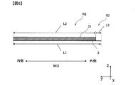
- the separation membrane body 2 is described as a laminate of a base material 201, a porous support layer 202 and a separation functional layer 203.
- the surface opened outside the separation functional layer 203 is the supply-side surface 21
- the surface opened outside the base material 201 is the transmission-side surface 22.
- the x-axis, y-axis, and z-axis direction axes are shown.
- the x-axis may be referred to as a first direction and the y-axis may be referred to as a second direction.
- the separation membrane main body 2 is rectangular, and the first direction and the second direction are parallel to the outer edge of the separation membrane main body 2.
- the first direction may be referred to as the width direction
- the second direction may be referred to as the length direction.
- the first direction (width direction) is represented by a CD arrow
- the second direction (length direction) is represented by an MD arrow.
- the separation membrane body a membrane having separation performance according to the method of use, purpose and the like is used.
- the separation membrane body may be formed of a single layer or a composite membrane including a separation functional layer and a substrate. As shown in FIG. 7, in the composite membrane, a porous support layer 202 may be formed between the separation functional layer 203 and the base material 201.
- the thickness of the separation functional layer is not limited to a specific numerical value, but is preferably 5 nm or more and 3000 nm or less in terms of separation performance and transmission performance.
- the thickness is preferably 5 nm or more and 300 nm or less.
- the thickness of the separation functional layer can be in accordance with a normal separation membrane thickness measurement method.
- the separation membrane is embedded with resin, and an ultrathin section is prepared by cutting the separation membrane, and the obtained section is subjected to processing such as staining. Thereafter, the thickness can be measured by observing with a transmission electron microscope.
- measurement can be made at intervals of 50 nm in the cross-sectional length direction of the pleat structure located above the porous support layer, the number of pleats can be measured, and the average can be obtained. it can.
- the separation function layer may be a layer having both a separation function and a support function, or may have only a separation function.
- the “separation function layer” refers to a layer having at least a separation function.
- the separation functional layer has both a separation function and a support function
- a layer containing cellulose, polyvinylidene fluoride, polyether sulfone, or polysulfone as a main component is preferably applied as the separation functional layer.
- X contains Y as a main component means that the Y content in X is 50% by mass, 70% by mass, 80% by mass, 90% by mass, or 95% by mass. It means that it is more than%.
- the total amount of these components only needs to satisfy the above range.
- a crosslinked polymer is preferably used in terms of easy control of the pore diameter and excellent durability.
- a polyamide separation functional layer obtained by polycondensation of a polyfunctional amine and a polyfunctional acid halide, an organic-inorganic hybrid functional layer, and the like are preferably used in terms of excellent separation performance of components in raw water.
- These separation functional layers can be formed by polycondensation of monomers on the porous support layer.
- the separation functional layer can contain polyamide as a main component.
- a film is formed by interfacial polycondensation of a polyfunctional amine and a polyfunctional acid halide by a known method. For example, by applying a polyfunctional amine aqueous solution to the porous support layer, removing the excess amine aqueous solution with an air knife or the like, and then applying an organic solvent solution containing a polyfunctional acid halide, the polyamide separation functional layer Is obtained.
- the separation functional layer may have an organic-inorganic hybrid structure containing Si element or the like.
- the separation functional layer having an organic-inorganic hybrid structure can contain, for example, the following compounds (A) and (B): (A) a silicon compound in which a reactive group and a hydrolyzable group having an ethylenically unsaturated group are directly bonded to a silicon atom, and (B) a compound other than the compound (A) and having an ethylenically unsaturated group Compound.
- the separation functional layer may contain a condensate of the hydrolyzable group of the compound (A) and a polymer of the ethylenically unsaturated group of the compounds (A) and / or (B). That is, the separation functional layer is A polymer formed by condensation and / or polymerization of only the compound (A), -The polymer formed by superposing
- the polymer includes a condensate.
- the compound (A) may be condensed through a hydrolyzable group.
- the hybrid structure can be formed by a known method.
- An example of a method for forming a hybrid structure is as follows.
- a reaction solution containing the compound (A) and the compound (B) is applied to the porous support layer.
- heat treatment may be performed.
- a polymerization initiator, a polymerization accelerator and the like can be added during the formation of the separation functional layer.
- the surface of the membrane may be hydrophilized with, for example, an alcohol-containing aqueous solution or an alkaline aqueous solution before use.
- the porous support layer is a layer that supports the separation functional layer, and is also referred to as a porous resin layer.
- the material used for the porous support layer and the shape thereof are not particularly limited, but may be formed on the substrate with a porous resin, for example.
- a porous resin for example.
- the porous support layer polysulfone, cellulose acetate, polyvinyl chloride, epoxy resin or a mixture and laminate of them is used, and polysulfone with high chemical, mechanical and thermal stability and easy to control pore size. Is preferably used.
- the porous support layer gives mechanical strength to the separation membrane and does not have separation performance like a separation membrane for components having a small molecular size such as ions.
- the pore size and pore distribution of the porous support layer are not particularly limited.
- the porous support layer may have uniform and fine pores, or the side on which the separation functional layer is formed. It may have a pore size distribution such that the diameter gradually increases from the surface to the other surface.
- the projected area equivalent circle diameter of the pores measured using an atomic force microscope or an electron microscope on the surface on the side where the separation functional layer is formed is 1 nm or more and 100 nm or less. preferable.
- the pores on the surface on the side where the separation functional layer is formed in the porous support layer preferably have a projected area equivalent circle diameter of 3 nm to 50 nm. .
- the thickness of the porous support layer is not particularly limited, but is preferably in the range of 20 ⁇ m or more and 500 ⁇ m or less, and more preferably 30 ⁇ m or more and 300 ⁇ m or less for the purpose of giving strength to the separation membrane.
- the morphology of the porous support layer can be observed with a scanning electron microscope, a transmission electron microscope, or an atomic microscope.
- a scanning electron microscope after peeling off the porous support layer from the substrate, it is cut by the freeze cleaving method to obtain a sample for cross-sectional observation.
- This sample is thinly coated with platinum, platinum-palladium or ruthenium tetrachloride, preferably ruthenium tetrachloride, and observed with a high-resolution field emission scanning electron microscope (UHR-FE-SEM) at an acceleration voltage of 3 kV to 6 kV.
- UHR-FE-SEM high-resolution field emission scanning electron microscope
- Hitachi S-900 electron microscope can be used. Based on the obtained electron micrograph, the film thickness of the porous support layer and the projected area equivalent circle diameter of the surface can be measured.
- the thickness and pore diameter of the porous support layer are average values, and the thickness of the porous support layer is an average value of 20 points measured at intervals of 20 ⁇ m in a direction perpendicular to the thickness direction by cross-sectional observation. Moreover, a hole diameter is an average value of each projected area circle equivalent diameter measured about 200 holes.
- the porous support layer is prepared by pouring an N, N-dimethylformamide (hereinafter referred to as DMF) solution of the above polysulfone on a base material described later, for example, a densely woven polyester cloth or non-woven fabric to a certain thickness. It can be produced by molding and wet coagulating it in water.
- DMF N, N-dimethylformamide
- the porous support layer is “Office of Saleen Water Research and Development Progress Report” No. 359 (1968).
- the polymer concentration, the temperature of the solvent, and the poor solvent can be adjusted.
- a predetermined amount of polysulfone is dissolved in DMF to prepare a polysulfone resin solution having a predetermined concentration.
- this polysulfone resin solution is applied to a substrate made of polyester cloth or nonwoven fabric to a substantially constant thickness, and after removing the surface solvent in the air for a certain period of time, the polysulfone is coagulated in the coagulation liquid.
- the separation membrane body can have a substrate.
- the base material it is preferable to use a fibrous base material in terms of strength, unevenness forming ability and fluid permeability.
- either a long fiber nonwoven fabric or a short fiber nonwoven fabric can be preferably used.
- the long fiber nonwoven fabric has excellent film-forming properties, when the polymer solution is cast, the solution penetrates through the permeation, the porous support layer peels off, and Can suppress the film from becoming non-uniform due to fluffing of the substrate and the like, and the occurrence of defects such as pinholes.
- the base material is made of a long-fiber non-woven fabric composed of thermoplastic continuous filaments, compared to short-fiber non-woven fabrics, it suppresses the occurrence of non-uniformity and film defects caused by fiber fluffing during casting of a polymer solution. be able to.
- the separation membrane is tensioned in the film-forming direction when continuously formed, it is preferable to use a long-fiber nonwoven fabric excellent in dimensional stability as a base material.
- the fibers in the surface layer on the side opposite to the porous support layer are preferably longitudinally oriented compared to the fibers in the surface layer on the porous support layer side in terms of moldability and strength. According to such a structure, not only a high effect of preventing membrane breakage by maintaining strength is realized, but also a laminate comprising a porous support layer and a substrate when imparting irregularities to the separation membrane The moldability is improved, and the uneven shape on the surface of the separation membrane is stabilized, which is preferable.
- the fiber orientation degree in the surface layer on the side opposite to the porous support layer of the long-fiber nonwoven fabric is preferably 0 ° or more and 25 ° or less, and the fiber orientation in the surface layer on the porous support layer side. It is preferable that the degree of orientation difference with respect to the degree is 10 ° to 90 °.
- a heating process is included, but a phenomenon occurs in which the porous support layer or the separation functional layer contracts due to heating.
- the shrinkage is remarkable in the width direction where no tension is applied in continuous film formation. Since shrinkage causes problems in dimensional stability and the like, a substrate having a small rate of thermal dimensional change is desired.
- the difference between the fiber orientation degree on the surface layer opposite to the porous support layer and the fiber orientation degree on the porous support layer side surface layer is 10 ° or more and 90 ° or less, the change in the width direction due to heat is suppressed. Can also be preferred.
- the fiber orientation degree is an index indicating the direction of the fibers of the nonwoven fabric base material constituting the porous support layer.
- the fiber orientation degree is an average value of angles between the film forming direction when continuous film forming is performed, that is, the longitudinal direction of the nonwoven fabric base material and the longitudinal direction of the fibers constituting the nonwoven fabric base material. is there. That is, if the longitudinal direction of the fiber is parallel to the film forming direction, the fiber orientation degree is 0 °. If the longitudinal direction of the fiber is perpendicular to the film forming direction, that is, if it is parallel to the width direction of the nonwoven fabric substrate, the degree of orientation of the fiber is 90 °. Accordingly, the closer to 0 ° the fiber orientation, the longer the orientation, and the closer to 90 °, the lateral orientation.
- the fiber orientation degree is measured as follows. First, 10 small piece samples are randomly collected from the nonwoven fabric. Next, the surface of the sample is photographed at 100 to 1000 times with a scanning electron microscope. In the photographed image, 10 fibers are selected for each sample, and the angle of the fibers in the longitudinal direction when the longitudinal direction of the nonwoven fabric is 0 ° is measured.
- the longitudinal direction of the nonwoven fabric refers to “Machine direction” at the time of manufacturing the nonwoven fabric.
- the longitudinal direction of the nonwoven fabric coincides with the film forming direction of the porous support layer and the MD direction in the figure.
- the CD direction in the figure corresponds to “Cross direction” at the time of manufacturing the nonwoven fabric.
- the angle is measured for a total of 100 fibers per nonwoven fabric.
- an average value is calculated from the angle in the longitudinal direction.
- the value obtained by rounding off the first decimal place of the obtained average value is the fiber orientation degree.
- the thickness of the substrate is preferably such that the total thickness of the substrate and the porous support layer is in the range of 30 ⁇ m to 300 ⁇ m, or in the range of 50 ⁇ m to 250 ⁇ m.
- (1-3) Permeation side channel material On the permeate side surface of the separation membrane body, a flow path material having a compression elastic modulus of 0.1 GPa or more and 5.0 GPa or less is fixed to the base material so as to form a permeate side flow path. “Provided to form a flow path on the permeate side” means that the permeated fluid that has permeated through the main body of the separation membrane can reach the water collecting pipe when the separation membrane is incorporated in a separation membrane element described later. It means that the road material is formed. Details of the configuration of the channel material are as follows.
- the compression elastic modulus of the channel material is preferably 0.1 GPa or more and 5.0 GPa or less.
- high-pressure operation is performed. Under high pressure, the flow path material is consolidated and the permeate-side flow path is narrowed, so that the flow resistance increases and the amount of water produced tends to decrease.
- the compression elastic modulus of the flow path material is 0.1 GPa or more, such a decrease in the amount of water can be suppressed.
- the compression elastic modulus of the flow path material is extremely high, the flow path material is easily broken when the separation membrane is surrounded.
- the compression elastic modulus is 5.0 GPa or less, the flow path material deformation at the time of pressure filtration can be suppressed, and the flow path can be stably formed.
- the compression modulus of the flow path material can be obtained from the slope of the straight line portion of the stress strain curve within the stress range in which the flow path material is elastically deformed. More specifically, the result measured by the measuring method in the examples described later only needs to satisfy the above-described range.
- the amount of deformation of the flow path material may be within a range described later by actually performing pressure filtration, the temperature of the raw water is 25 ° C. or less, and the pressure is 5.5 MPa or less. If the deformation rate of the height of the flow path material is 40% or less when operated under these conditions, it is suitable for application to seawater desalination.
- the flow rate can be applied to the irrigation element by having a deformation rate of 30% or less.
- the deformation rate is obtained by (the height of the channel material after operation under the above-mentioned conditions / the height of the channel material before operation) ⁇ 100.
- the bending resistance of the separation membrane to which the flow path material is fixed is preferably 400 mm or less, more preferably 350 mm or less, and particularly preferably 200 mm or less.
- the bending resistance is measured according to ISO 13934-1 1999. That is, the bending resistance is measured by the following procedure using a horizontal table having a horizontal plane and a 45 ° slope. First, a section having a width of 25 mm is cut out from the separation membrane as a sample. Next, the sample is placed on the horizontal plane so that the separator functional layer faces the horizontal plane, and the other end of the sample is pressed with a metal plate with one end of the sample aligned with the boundary between the slope and the horizontal plane. Further, while holding the sample, the metal plate is gently slid toward the boundary between the slope and the horizontal plane. As the metal plate moves, the sample is pushed out from the boundary between the slope and the horizontal plane.
- the length (mm) of the sample extruded is measured.
- the measured length is the bending resistance of the separation membrane.
- the channel material 31 is preferably formed of a material different from that of the separation membrane body 2.
- the different material means a material having a composition different from that of the material used in the separation membrane body 2.
- the composition of the flow path member 31 is preferably different from the composition of the surface of the separation membrane body 2 on which the flow path material 31 is formed, and is different from the composition of any layer forming the separation membrane body 2. It is preferable.
- the material constituting the channel material is not limited to a specific substance, but a resin is preferably used. Specifically, in view of chemical resistance, ethylene vinyl acetate copolymer resin, polyolefin such as polyethylene and polypropylene, and polyolefin copolymer are preferable.
- urethane resin epoxy resin, polyethersulfone, polyacrylonitrile, polyvinyl chloride, polyvinylidene chloride, polyvinyl alcohol, ethylene-vinyl alcohol copolymer, polystyrene, styrene-acrylonitrile copolymer, Styrene-butadiene-acrylonitrile copolymer, polyacetal, polymethyl methacrylate, methacryl-styrene copolymer, cellulose acetate, polycarbonate, polyethylene terephthalate, polybutadiene terephthalate and fluororesin (ethylene trifluoride chloride, polyvinylidene fluoride, tetrafluoroethylene) , Tetrafluoroethylene-hexafluoropropylene copolymer, tetrafluoroethylene-perfluoroalkoxyethylene copolymer, tetrafluoroethylene-ethylene copolymer
- a composite material can also be applied as the material of the channel material.
- the composite material include a material containing the above-described resin as a base material and further containing a filler.
- the compression elastic modulus of the channel material can be increased by adding a filler such as a porous inorganic material to the base material.
- a filler such as a porous inorganic material to the base material.
- alkaline earth metal silicates such as sodium silicate, calcium silicate and magnesium silicate, metal oxides such as silica, alumina and titanium oxide
- alkaline earth metals such as calcium carbonate and magnesium carbonate.
- Carbonate, pure meteorite, meteorite powder, caustic clay, wollastonite, sepiolite, attapulgite, kaolin, clay, bentonite, gypsum, talc, etc. can be used as fillers.
- the addition amount of a filler will not be specifically limited if it is a range which does not impair the effect of this invention.
- a tricot that has been widely used in the past is a knitted fabric, and is composed of three-dimensionally intersecting yarns. That is, the tricot has a two-dimensionally continuous structure. When such a tricot is applied as a channel material, the height of the channel is smaller than the thickness of the tricot. That is, the entire thickness of the tricot cannot be used as the height of the flow path.
- the flow path materials 31 shown in FIG. 1 and the like are arranged so as not to overlap each other. Therefore, the height (that is, the thickness) of the channel material 31 of the present embodiment is all utilized as the height of the channel groove. Therefore, when the flow path member 31 of the present embodiment is applied, the flow path is higher than when a tricot having the same thickness as the height of the flow path member 31 is applied. That is, since the cross-sectional area of the flow path becomes larger, the flow resistance becomes smaller.
- discontinuous is a state in which a plurality of flow path members are provided at intervals. That is, when the flow path material 31 in one separation membrane is peeled from the separation membrane main body 2, a plurality of flow path materials 31 separated from each other are obtained.
- members such as nets, tricots, and films exhibit a continuous and integral shape even when separated from the separation membrane body 2.
- the separation membrane 1 can suppress the pressure loss when incorporated in the separation membrane element 100 described later.
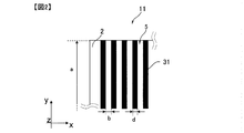
- the flow path material 31 is formed discontinuously only in the first direction (length direction of the separation membrane), and in FIG. 3, the first direction (length direction of the separation membrane). ) And the second direction (the width direction of the separation membrane).
- the permeate-side flow path 5 is formed in the space between the adjacent flow path materials 31.
- the separation membrane is preferably arranged in the separation membrane element so that the second direction coincides with the winding direction. That is, in the separation membrane element, in the separation membrane, the first direction (width direction of the separation membrane) is parallel to the longitudinal direction of the water collection pipe 6, and the second direction (length direction of the separation membrane) is the longitudinal direction of the water collection pipe 6. It is preferable to be arranged so as to be orthogonal to the direction.
- the flow path material 31 is provided discontinuously in the first direction, and in the form shown in FIGS. 2 and 5, it is provided so as to be continuous from one end to the other end of the separation membrane body 2 in the second direction.
- the flow path material 31 is arranged so as to continue from the inner end to the outer end of the separation membrane 1 in the winding direction.
- the inner side in the winding direction is the side close to the water collecting pipe in the separation membrane, and the outer side in the winding direction is the side far from the water collecting pipe in the separation membrane.
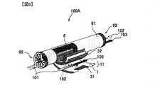
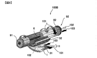
- FIG. 5 is an explanatory view schematically showing a separation membrane element 100 in which the separation membrane 1 is wound around the water collecting pipe 6.
- the separation membrane 1 is described as one surface of the separation membrane leaf.
- an arrow indicated by CD indicates the longitudinal direction of the water collecting pipe 6 and the width direction of the separation membrane.
- An arrow indicated by MD indicates the length direction of the separation membrane and the direction of winding around the water collecting pipe 6.
- the passage material is “continuous in the second direction” means that the passage material is provided without interruption as shown in FIG. 2 and the passage material is interrupted as shown in FIG. It includes both cases where the channel material is substantially continuous.
- the “substantially continuous” form preferably satisfies that the distance e between the flow path materials in the second direction (that is, the length of the portion where the flow path material is interrupted) is 5 mm or less.
- the distance e is more preferably 1 mm or less, and further preferably 0.5 mm or less.
- the total value of the intervals e included from the beginning to the end of the line of flow path materials arranged in the second direction is preferably 100 mm or less, more preferably 30 mm or less, and more preferably 3 mm or less. Further preferred. In the form of FIG. 2, the interval e is 0 (zero).
- membrane drop is suppressed during pressure filtration.
- Membrane sagging is that the membrane falls into the channel and narrows the channel.
- the channel material 31 is discontinuously provided not only in the first direction but also in the second direction. That is, the channel material 31 is provided at intervals in the length direction. However, as described above, the passage material 31 is substantially continuous in the second direction, so that the film sagging is suppressed. In addition, by providing the discontinuous flow path material 31 in the two directions as described above, the contact area between the flow path material and the fluid is reduced, so that the pressure loss is reduced.
- this form is a configuration in which the flow path 5 includes a branch point. That is, in the configuration of FIG. 3, the permeating fluid is divided by the flow path material 31 while flowing through the flow path 5, and can further merge downstream.
- the flow path material 31 is provided so as to be continuous from one end to the other end of the separation membrane body 2 in the second direction.
- the flow path material 31 is divided into a plurality of portions in the second direction, but the plurality of portions are provided so as to be lined up from one end to the other end of the separation membrane body 2.
- the channel material is “provided from one end to the other end of the separation membrane body” means that the channel material is provided up to the edge of the separation membrane body 2 and the channel material is provided in the vicinity of the edge. Includes both forms with no areas. That is, the flow path material only needs to be distributed in the second direction to such an extent that a flow path on the permeation side can be formed, and there may be a portion where the flow path material is not provided in the separation membrane body. For example, in the surface on the permeate side, a flow path material does not need to be provided in a portion (in other words, a contact portion) bonded to another separation membrane. Moreover, the area
- positioned may be provided in some places, such as the edge part of a separation membrane, for the reason on the other specification or manufacture.
- the flow path material 31 can be distributed almost uniformly over the entire separation membrane main body. However, similarly to the distribution in the second direction, it is not necessary to provide the flow path material at the bonding portion with the other separation membrane on the permeate side surface. Moreover, the area
- positioned may be provided in some places, such as the edge part of a separation membrane, for the reason on the other specification or manufacture.
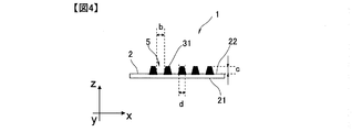
- a Length of the separation membrane body 2 b: Spacing of the flow path material 31 in the width direction of the separation membrane body 2 c: Height of the flow path material (the flow path material 31 and the permeation side surface 22 of the separation membrane body 2 Difference in height) d: width of the channel material 31 e: interval of the channel material in the length direction of the separation membrane body 2 f: length of the channel material 31
- a, b, c, d, e, f For measurement of values a, b, c, d, e, f
- a commercially available shape measuring system or a microscope can be used. Each value is obtained by performing measurement at 30 or more locations on one separation membrane, and calculating an average value by dividing the sum of these values by the number of measurement total locations. Thus, each value obtained as a result of the measurement at at least 30 locations should satisfy the range described below.
- the length a is a distance from one end of the separation membrane body 2 to the other end in the second direction (length direction of the separation membrane). When this distance is not constant, the length a can be obtained by measuring this distance at 30 or more positions in one separation membrane body 2 and obtaining an average value.
- the interval b between the adjacent flow path members 31 in the first direction corresponds to the width of the flow path 5.
- the width of one flow path 5 is not constant in one cross section, that is, when the side surfaces of two adjacent flow path materials 31 are not parallel, the maximum value of the width of one flow path 5 within one cross section
- the average value of the minimum values is measured, and the average value is calculated.
- the distance between the upper parts of the two adjacent channel materials 31 and the lower part is measured and the average value is calculated.
- the distance between the flow path materials 31 is measured at any 30 or more cross sections, and the average value is calculated for each cross section.
- interval b is calculated by calculating further the arithmetic mean value of the average value obtained in this way.
- the interval b is preferably 0.05 mm or more, 0.2 mm or more, or 0.3 mm or more. Further, in terms of suppressing film sagging, the interval b is preferably 5 mm or less, 3 mm or less, 2 mm or less, or 0.8 mm or less.
- the interval b is preferably 0.2 mm or more and 5 mm or less, and within this range, the pressure loss can be reduced while suppressing the film sagging.
- the distance b is more preferably 0.05 mm or more and 3 mm or less, 0.2 mm or more and 2 mm or less, and further preferably 0.3 mm or more and 0.8 mm or less.
- the height c is a height difference between the flow path material and the surface of the separation membrane main body. As shown in FIG. 4, the height c is a difference in height between the highest portion of the channel material 31 and the permeation side surface of the separation membrane main body in a cross section perpendicular to the second direction. That is, in the height, the thickness of the portion impregnated in the base material is not considered.
- the height c is a value obtained by measuring the heights of the flow path materials 31 at 30 or more locations and averaging them.
- the height c of the flow path material may be obtained by observing a cross section of the flow path material in the same plane, or may be obtained by observing cross sections of the flow path material in a plurality of planes.
- the height c can be appropriately selected according to the use condition and purpose of the element, but may be set as follows, for example.
- the height c is preferably 0.03 mm or more, 0.05 mm or more, or 0.1 mm or more.
- the smaller the height c the larger the number of films filled per element. Therefore, the height c is preferably 0.8 mm or less, 0.4 mm or less, or 0.32 mm or less.
- the height c is preferably 0.03 mm to 0.8 mm (30 ⁇ m to 800 ⁇ m), and preferably 0.05 mm to 0.4 mm. Preferably, it is 0.1 mm or more and 0.32 mm or less.
- the difference in height between two adjacent channel materials is small. If the difference in height is large, the separation membrane is distorted during pressure filtration, so that defects may occur in the separation membrane.
- the difference in height between two adjacent channel materials is preferably 0.1 mm or less (100 ⁇ m or less), more preferably 0.06 mm or less, and further preferably 0.04 mm or less.
- the maximum height difference of all the channel materials provided in the separation membrane is preferably 0.25 mm or less, particularly preferably 0.1 mm or less, and further preferably 0.03 mm or less. .
- the width d of the channel material 31 is measured as follows. First, in one cross section perpendicular to the first direction (the width direction of the separation membrane), an average value of the maximum width and the minimum width of one flow path material 31 is calculated. That is, in the channel material 31 with a thin upper part and a thick lower part as shown in FIG. 4, the width of the lower part and the upper part of the channel material are measured, and the average value is calculated. By calculating such an average value in at least 30 cross-sections and calculating the arithmetic average thereof, the width d per film can be calculated.
- the width d of the channel material 31 is preferably 0.2 mm or more, and more preferably 0.3 mm or more. When the width d is 0.2 mm or more, the shape of the flow path material can be maintained even when pressure is applied to the flow path material 31 during operation of the separation membrane element, and the permeation side flow path is stably formed.
- the width d is preferably 2 mm or less, and more preferably 1.5 mm or less. When the width d is 2 mm or less, a sufficient flow path on the permeate side can be secured.
- the pressure applied to the flow path material can be dispersed.
- the channel material 31 is formed so that its length is larger than its width. Such a long channel material 31 is also referred to as a “wall-like object”.
- the interval e between the flow path members 31 in the second direction is the shortest distance between the flow path members 31 adjacent in the second direction (the length direction of the separation membrane).
- the flow path material 31 is provided continuously from one end to the other end of the separation membrane body 2 in the second direction (in the separation membrane element, from the inner end to the outer end in the winding direction). If it is, the interval e is 0 mm.
- the interval e is preferably 5 mm or less, more preferably 1 mm or less, and further preferably 0.5 mm or less. .
- the distance e is within the above range, the mechanical load on the film is small even when the film is dropped, and the pressure loss due to the blockage of the flow path can be relatively small.
- interval e is 0 mm.
- the length f of the flow path material 31 is the length of the flow path material 31 in the length direction of the separation membrane body 2 (that is, the second direction).
- the length f is obtained by measuring the length of 30 or more flow path members 31 in one separation membrane 1 and calculating the average value.
- the length f of the channel material may be equal to or less than the length a of the separation membrane body.
- the length f of the flow path material is continuously provided from the inner end to the outer end in the winding direction of the separation membrane 1. Point to.
- the length f is preferably 10 mm or more, more preferably 20 mm or more. Since the length f is 10 mm or more, the flow path is secured even under pressure.
- the flow path material of the present embodiment can reduce pressure loss as compared with a flow path material having a continuous shape like a conventional tricot.
- the leaf length can be made larger than that of the conventional technique even if the pressure loss is equal. If the leaf length can be increased, the number of leaves can be reduced.
- the number of leaves can be particularly reduced by setting the dimensions af to satisfy the following mathematical formula. i) a 2 f 2 (b + c) 2 (b + d) ⁇ 10 ⁇ 6 / b 3 c 3 (e + f) 2 ⁇ 1400 and ii) 850 ⁇ a ⁇ 7000 and iii) b ⁇ 2 and iv) c ⁇ 0.5 And v) 0.15 ⁇ df / (b + d) (e + f) ⁇ 0.85
- pressure loss is reduced as compared with a flow path material having a continuous shape like a conventional tricot, so that the leaf length can be increased. . Therefore, even if the number of leaves per separation membrane element is reduced, a separation membrane element having excellent separation performance can be provided.
- mm can be adopted as the unit of length.
- the shape of the channel material is not particularly limited, but a shape that reduces the flow resistance of the channel and stabilizes the channel when permeated can be selected.
- the shape of the flow path material in any cross section perpendicular to the surface direction of the separation membrane, may be a straight column shape, a trapezoidal shape, a curved column shape, or a combination thereof.
- the ratio of the length of the upper base to the length of the lower base of the flow path material is preferably 0.6 or more and 1.4 or less, and is 0.8 or more and 1.2 or less. Further preferred.
- the shape of the flow path material is preferably a straight column shape perpendicular to the separation membrane surface described later from the viewpoint of reducing flow resistance.
- the channel material may be formed so that the width becomes smaller at a higher location, or conversely, the channel material may be formed so that the width becomes wider at a higher location, or the height from the surface of the separation membrane. Regardless, it may be formed to have the same width.
- the upper side of the cross section of the flow path material may be rounded.
- the channel material can be formed of a thermoplastic resin. If the flow path material is a thermoplastic resin, the shape of the flow path material can be freely changed to satisfy the required separation characteristics and permeation performance conditions by changing the processing temperature and the type of thermoplastic resin to be selected. Can be adjusted.
- the shape of the separation membrane of the flow path material in the planar direction may be linear as a whole as shown in FIGS. 2 and 3, and other shapes are, for example, curved, sawtooth, and wavy. There may be.
- the channel material may be a broken line or a dot. From the viewpoint of reducing the flow resistance, a dot shape or a broken line shape is preferable. However, since the flow path material is interrupted, the number of places where film sagging occurs during pressure filtration increases.
- the adjacent flow path materials may be arranged substantially parallel to each other. “Arranged substantially in parallel” means, for example, that the channel material does not intersect on the separation membrane, the angle formed by the longitudinal direction of two adjacent channel materials is 0 ° or more and 30 ° or less, It includes that the angle is from 0 ° to 15 °, and that the angle is from 0 ° to 5 °.
- the angle formed by the longitudinal direction of the flow path material and the longitudinal direction of the water collecting pipe is preferably 60 ° or more and 120 ° or less, more preferably 75 ° or more and 105 ° or less, and 85 ° or more and 95 °. More preferably, it is as follows. When the angle formed by the longitudinal direction of the flow path material and the longitudinal direction of the water collecting pipe is within the above range, the permeated water is efficiently collected in the water collecting pipe.
- the separation membrane body can be prevented from dropping when the separation membrane body is pressurized in the separation membrane element.
- the contact area between the separation membrane main body and the flow path material is large, that is, the area of the flow path material relative to the area of the separation membrane main body (projected area on the membrane surface of the separation membrane main body) is large.
- the cross-sectional area of a flow path is wide. The cross section of the flow path is to secure a large contact area between the separation membrane body perpendicular to the longitudinal direction of the flow path and the flow path material and to ensure a wide cross sectional area of the flow path.
- the cross-sectional shape is preferably a concave lens shape.
- the flow path member 31 may have a straight column shape having no change in width in a cross-sectional shape in a direction perpendicular to the winding direction.
- the cross-sectional shape in the direction perpendicular to the winding direction has a trapezoidal wall-like object having a change in width, an elliptic cylinder, an elliptic cone, four A shape like a pyramid or a hemisphere may be sufficient.
- the shape of the channel material is not limited to the shape shown in FIGS. Change the processing temperature and the type of hot-melt resin to be selected when the flow path material is placed on the permeate side surface of the separation membrane body by, for example, a hot melt method by fixing a molten material.
- the shape of the flow path material can be freely adjusted so that the required separation characteristics and permeation performance conditions can be satisfied.
- the planar shape of the channel material 31 is linear in the length direction.
- the flow path member 31 can be changed to another shape as long as it is convex with respect to the surface of the separation membrane body 2 and does not impair the desired effect as the separation membrane element. That is, the shape of the flow path material in the plane direction may be a curved line, a wavy line, or the like.
- a plurality of flow path materials included in one separation membrane may be formed so that at least one of width and length is different from each other.
- the projected area ratio of the flow path material to the permeation side surface of the separation membrane is 0.03 or more and 0.85 or less, particularly in terms of reducing the flow resistance of the permeation side flow path and forming the flow path stably. Is preferably 0.15 or more and 0.85 or less, more preferably 0.2 or more and 0.75 or less, and further preferably 0.3 or more and 0.6 or less.
- the projected area ratio is a value obtained by dividing the projected area of the flow path material obtained when the separation membrane is cut out at 5 cm ⁇ 5 cm and projected onto a plane parallel to the surface direction of the separation membrane by the cut-out area (25 cm 2 ). It is. This value can also be expressed by df / (b + d) (e + f) described in the above equation v).
- the water that has permeated through the separation membrane passes through the permeation side flow path 5 and is collected in the water collecting pipe 6.
- the separation membrane water that has passed through a region far from the water collecting pipe, that is, a region in the vicinity of the outer end in the winding direction (region near the right end in FIG. 5) It merges with the water that has passed through the inner area and heads for the water collecting pipe 6. Therefore, in the permeate side flow path, the amount of water present is smaller in the direction far from the water collecting pipe 6.
- the length L3 in the second direction (the length direction of the separation membrane) of the region R3, which is a region where the permeation-side flow path is not formed, is the length L1 in the second direction of the entire separation membrane ( It corresponds to the above-mentioned “a”.)
- the ratio of occupying with respect to “a” is preferably 0% or more and 30% or less, more preferably 0% or more and 10% or less, and particularly preferably 0% or more and 3% or less. This ratio is called a defect ratio.
- the defect rate is represented by (L3 / L1) ⁇ 100 in FIG.
- FIG. 6 shows a configuration in which the permeation-side channel material is not provided in the region R3.
- the region 3 may be a region provided with a permeate-side flow path material continuous in the width direction.
- FIG. 6 is a cross-sectional view of the separation membrane main body 2 and the end portion on the outer side in the winding direction of the permeate-side flow path member 31 cut in the length direction of the permeate-side flow path member 31.
- the permeation-side flow path material 31 is fixed to the separation membrane main body 2 and extends to the front of the outer end in the winding direction of the separation membrane main body 2.
- FIG. 6 shows a form in which the permeate-side flow path material 31 is continuously provided in the length direction, but the various forms described above are applied as the permeate-side flow path material 31. Is as already described.
- a region where the permeate side channel material 31 is provided is indicated by R2, and a region where the permeate side channel material 31 is not provided is indicated by R3.
- the length of the separation membrane body 2 in the MD direction is L1
- the length of the permeation side flow path material 31 in the MD direction is L2
- the MD of the region R3 where the permeation side flow path material 31 is not present is indicated by L3.
- the MD direction represents the length direction of the separation membrane and the winding direction of the separation membrane.
- the separation membrane element 100 includes the water collecting pipe 6 and the separation membrane 1 wound around the water collecting pipe 6.
- the separation membrane 1 is wound around the water collecting pipe 6 and is arranged so that the width direction of the separation membrane is along the longitudinal direction of the water collecting pipe 6. As a result, the separation membrane 1 is disposed such that the length direction is along the winding direction.
- the channel material 31 that is a wall-like material is discontinuously arranged at least in the longitudinal direction of the water collecting pipe 6 on the permeation side surface 22 of the separation membrane 1. That is, the flow path 5 is formed to be continuous from the outer end to the inner end of the separation membrane in the winding direction.
- the permeated water can easily reach the central pipe, that is, the flow resistance is reduced, so that a large amount of fresh water can be obtained.
- “Inside in winding direction” and “outside in winding direction” are as shown in FIG. That is, the “inner end portion in the winding direction” and the “outer end portion in the winding direction” correspond to the end portion closer to the water collecting pipe 6 and the far end portion in the separation membrane 1, respectively.
- the flow path material does not have to reach the edge of the separation membrane, for example, at the outer end of the envelope membrane in the winding direction and the end of the envelope membrane in the longitudinal direction of the water collecting pipe,
- the channel material may not be provided.
- the separation membrane forms a membrane leaf 4 (sometimes simply referred to as “leaf” in this document).
- the separation membrane 1 is arranged so that the supply-side surface 21 faces the supply-side surface 71 of another separation membrane 7 with a supply-side flow path material (not shown) interposed therebetween.
- a supply-side flow path is formed between the supply-side surfaces of the separation membranes facing each other.
- the two membrane leaves 4 are overlapped so that the separation membrane 1 and the separation membrane 7 of the other membrane leaf facing the permeation side surface 22 of the separation membrane 1 form an envelope-like membrane.
- the envelope-like membrane between the opposite permeate side surfaces, in the rectangular shape of the separation membrane, only one side inside the winding direction is opened, and the other three sides are sealed so that the permeate flows into the water collecting pipe 6. Stopped. The permeate is isolated from the raw water by this envelope membrane.
- Sealing includes a form bonded by an adhesive or hot melt, a form fused by heating or laser, and a form in which a rubber sheet is sandwiched. Sealing by adhesion is particularly preferable because it is the simplest and most effective.
- the inner end in the winding direction is closed by folding or sealing. Since the supply side surface of the separation membrane is sealed rather than folded, bending at the end of the separation membrane hardly occurs. By suppressing the occurrence of bending in the vicinity of the crease, the generation of voids between the separation membranes and the occurrence of leaks due to the voids are suppressed when wound.
- the recovery rate of the envelope-like film is obtained as follows. That is, an air leak test (air leak test) of the separation membrane element is performed in water, and the number of envelope-shaped membranes in which the leak has occurred is counted. Based on the count result, the ratio of (number of envelope films in which air leak has occurred / number of envelope films used for evaluation) is calculated as the recovery rate of the envelope film.
- the specific air leak test method is as follows.
- the end of the central pipe of the separation membrane element is sealed, and air is injected from the other end.
- the injected air passes through the holes of the water collecting pipe and reaches the permeation side of the separation membrane.
- the separation membrane is not sufficiently folded and bent near the fold, Will move through the gap.
- the air moves to the supply side of the separation membrane, and the air reaches the water from the end (supply side) of the separation membrane element.
- air leak can be confirmed as the generation of bubbles.
- the separation membranes facing each other may have the same configuration or different configurations. That is, in the separation membrane element, at least one of the two permeate-side surfaces facing each other only needs to be provided with the above-described permeation-side flow path material, and therefore the separation membrane element does not include the permeation-side flow path material. Separation membranes may be alternately stacked. However, for convenience of explanation, in the separation membrane element and the explanation related thereto, the “separation membrane” includes a separation membrane that does not include the permeate-side flow path material (for example, a membrane that has the same configuration as the separation membrane main body).
- the separation membranes facing each other on the permeate side surface or the supply side surface may be two different separation membranes, or may be a single membrane folded.
- the separation membrane 1 is provided with the permeation side channel material 31.
- the permeation side flow path member 31 a permeation side flow path is formed inside the envelope-shaped membrane, that is, between the permeation side surfaces of the facing separation membranes.
- the separation membrane element 100 includes a channel material (not shown) having a projected area ratio with respect to the separation membrane 1 exceeding 0 and less than 1 between the surfaces on the supply side of the facing separation membrane.
- the projected area ratio of the supply-side channel material is preferably 0.03 or more and 0.50 or less, more preferably 0.10 or more and 0.40 or less, and particularly preferably 0.15 or more and 0.35 or less. .
- the projected area ratio refers to the projected area obtained when the separation membrane and the supply-side channel material are cut out at 5 cm ⁇ 5 cm, and the supply-side channel material is projected onto a plane parallel to the surface direction of the separation membrane. Divided value.
- the height of the supply-side channel material is preferably more than 0.5 mm and not more than 2.0 mm, and more preferably not less than 0.6 mm and not more than 1.0 mm in consideration of the balance of each performance and operation cost as described later.
- the shape of the supply-side channel material is not particularly limited, and may have a continuous shape or a discontinuous shape.
- Examples of the channel material having a continuous shape include members such as a film and a net.
- the continuous shape means that it is continuous over the entire range of the flow path material.
- the continuous shape may include a portion where a part of the flow path material is discontinuous to such an extent that a problem such as a decrease in the amount of water produced does not occur.
- the definition of “discontinuity” is as described for the passage-side channel material.
- the material of the supply side channel material is not particularly limited, and may be the same material as the separation membrane or a different material.
- a difference in height can be imparted to the supply side of the separation membrane by a method such as embossing, hydraulic forming, or calendering.
- the embossing method examples include roll embossing, and the pressure and processing temperature for carrying out this can be determined as appropriate according to the melting point of the separation membrane.
- the linear pressure is preferably 10 kg / cm or more and 60 kg / cm or less
- the heating temperature is preferably 40 ° C. or more and 150 ° C. or less.
- it has a porous support layer containing heat resistant resins, such as polysulfone, it is preferable that it is 10 to 70 kg / cm of linear pressure, and roll heating temperature 70 to 160 degreeC is preferable.
- a winding speed of 1 m / min to 20 m / min is preferable.
- the shape of the roll handle is not particularly limited, but it is important to reduce the flow resistance of the flow path and stabilize the flow path when supplying and permeating fluid to the separation membrane element. is there.
- the difference in height of the supply side surface of the separation membrane that can be imparted by embossing can be freely adjusted by changing the pressure heat treatment conditions so as to satisfy the conditions that require separation characteristics and water permeation performance.
- the difference in height on the supply side surface of the separation membrane is too deep, the flow resistance is reduced, but the number of membrane leaves that can be filled in the vessel when the element is formed is reduced. If the height difference is small, the flow resistance of the flow path increases, and the separation characteristics and water permeation performance deteriorate. Therefore, the fresh water generation capacity of the element is reduced, and the operation cost for increasing the fresh water generation amount is increased.
- the difference in height of the supply side surface of the separation membrane is preferably more than 0.5 mm and preferably 2.0 mm or less, and 0.6 mm or more. 1.0 mm or less is more preferable.
- the height difference on the supply side surface of the separation membrane can be obtained by the same method as in the case of the height difference on the separation membrane permeation side described above.
- the groove width is preferably 0.2 mm or more and 10 mm or less, more preferably 0.5 mm or more and 3 mm or less.
- the pitch should be appropriately designed between 1/10 and 50 times the groove width.
- the groove width is the part that sinks on the surface where the height difference exists, and the pitch is the horizontal from the highest point of the high part to the highest part of the adjacent high part on the surface where the height difference exists. It is distance.
- the projected area ratio of the portion that becomes convex by embossing is preferably 0.03 or more and 0.5 or less, more preferably 0.10 or more and 0.40, for the same reason as in the case of the supply-side channel material.
- it is particularly preferably 0.15 or more and 0.35 or less.
- the “height difference” in the surface of the separation membrane is the difference in height between the surface of the separation membrane body and the apex of the flow channel material (that is, the height of the flow channel material). Is the difference in height between the concave and convex portions.
- the water collection pipe 6 is not particularly limited as long as it is configured to allow permeate to flow therethrough.
- a cylindrical member having a side surface provided with a plurality of holes is used as the water collecting pipe 6, for example.
- FIGS. 8 to 10 show separation membrane elements 100A, 100B, and 100C of the first to third forms.
- FIG. 8 is an explanatory view showing the separation membrane element 100 ⁇ / b> A of the first embodiment partially disassembled, and a plurality of separation membranes 1 are wound around the water collecting pipe 6.
- the separation membrane element 100A further includes the following configuration.
- the separation membrane element 100A includes end plates 92 with holes at both ends (that is, the first end and the second end).
- an outer package 81 is wound around the outer peripheral surface of the wound separation membrane (hereinafter referred to as “wrapping body”).
- the holeless end plate 91 described later does not include a hole through which raw water can pass, whereas the holed end plate 92 includes a plurality of holes through which the raw water can pass.
- the separation membrane 1 forms an envelope-shaped membrane 11, and the permeation-side flow path material 31 is arranged inside the envelope-shaped separation membrane 11 as described above.
- a supply-side channel material 32 is disposed between the envelope-shaped films 11.
- the permeation-side channel material 31 is shown as a dot shape, but the shape of the permeation-side channel material is not limited to this shape as described above.
- the raw water 101 supplied from the first end of the separation membrane element 100A flows into the supply-side flow path through the hole of the end plate 92. In this way, the raw water 101 in contact with the supply side surface of the separation membrane 1 is separated into the permeated water 102 and the concentrated water 103 by the separation membrane 1.
- the permeated water 102 flows into the water collecting pipe 6 through the permeate side flow path.
- the permeated water 102 that has passed through the water collection pipe 6 flows out of the separation membrane element 100A from the second end of the separation membrane element 100A.
- the concentrated water 103 flows out of the separation membrane element 100A from the hole of the end plate 92 provided at the second end through the supply side flow path.
- the separation membrane element 100B includes an end plate 91 that is arranged at the first end and has no holes, and an end plate 92 that is arranged at the second end and has holes. Further, the separation membrane element 100B includes a porous member 82 that is further wound around the outermost surface of the surrounded separation membrane 1.
- the porous member 82 a member having a plurality of holes through which raw water can pass is used. These holes provided in the porous member 82 may be referred to as raw water supply ports. As long as the porous member 82 has a plurality of holes, the material, size, thickness, rigidity and the like are not particularly limited. By adopting a member having a relatively small thickness as the porous member 82, the membrane area per unit volume of the separation membrane element can be increased.
- the thickness of the porous member 82 is, for example, 1 mm or less, 0.5 mm or less, or 0.2 mm or less.
- the porous member 82 may be a member having flexibility or flexibility that can be deformed so as to follow the outer peripheral shape of the wound body. More specifically, as the porous member 82, a net, a porous film, or the like can be applied. The net and the porous film may be formed in a cylindrical shape so that the wound body can be accommodated therein, or may be long and wound around the wound body.
- the porous member 82 is disposed on the outer peripheral surface of the separation membrane element 100B. By providing the porous member 82 in this manner, holes are provided on the outer peripheral surface of the separation membrane element 100B. It can be said that the “outer peripheral surface” is a portion excluding the first end surface and the second end surface in the entire outer peripheral surface of the separation membrane element 100B. In this embodiment, the porous member 82 is disposed so as to cover almost the entire outer peripheral surface of the wound body.
- raw water is supplied from the outer peripheral surface of the separation membrane element 100B (the outer peripheral surface of the wound body). Therefore, even if the separation membrane element 100B is repeatedly operated or the separation membrane element 100B is operated under a high pressure condition, deformation of the wound body due to the surrounding separation membrane 1 and the like being pushed out in the longitudinal direction ( It is possible to suppress so-called telescopes. Furthermore, in this embodiment, since raw
- the raw water does not flow into the separation membrane element 100B from the surface of the first end.
- the raw water 101 is supplied to the separation membrane 1 through the porous member 82 from the outer peripheral surface of the separation membrane element 100B.
- the raw water 101 supplied in this way is divided into permeated water 102 and concentrated water 103 by the separation membrane.
- the permeated water 102 passes through the water collection pipe 6 and is taken out from the second end of the separation membrane element 100B.
- the concentrated water 103 flows out of the separation membrane element 100B through the hole of the end plate 92 with a hole at the second end.
- the separation membrane element 100C is the same as the element of the second embodiment except that the separation membrane element 100C is provided at each of the first end and the second end and includes an end plate 92 having holes.
- the separation membrane element 100C includes a porous member 82, like the separation membrane element 100B.
- the raw water 101 is not only supplied from the outer peripheral surface of the separation membrane element 100C to the envelope through the hole of the porous member 82, but also the end plate 92 with a hole at the first end.
- the separation membrane element 100 ⁇ / b> C is supplied to the winding body through the first hole.
- the permeated water 102 and the concentrated water 103 are discharged from the second end to the outside of the separation membrane element 100C, similarly to the separation membrane element 100A of the first form.
- the manufacturing method of a separation membrane element includes the process of manufacturing a separation membrane.
- the step of producing the separation membrane includes at least the following steps: Preparing a separation membrane body having a base material and a separation functional layer; A step of softening a material having a composition different from that of the separation membrane body by heat, The softened material is disposed on the base material side surface of the separation membrane main body to form a permeation-side flow path material, and the material is solidified to form the permeation side on the separation membrane main body.
- a step of fixing the flow path material is performed by heat.
- Resin is dissolved in a good solvent, and the resulting resin solution is cast on a substrate and immersed in pure water to combine the porous support layer and the substrate. Thereafter, as described above, a separation functional layer is formed on the porous support layer. Furthermore, chemical treatment such as chlorine, acid, alkali, nitrous acid, etc. is performed to enhance separation performance and permeation performance as necessary, and the monomer is washed to produce a continuous sheet of the separation membrane body.
- chemical treatment such as chlorine, acid, alkali, nitrous acid, etc. is performed to enhance separation performance and permeation performance as necessary, and the monomer is washed to produce a continuous sheet of the separation membrane body.
- a method for manufacturing a separation membrane includes a step of providing a discontinuous channel material on the permeation side surface of the separation membrane body. This step may be performed at any time during the manufacture of the separation membrane.
- the flow path material may be provided before the porous support layer is formed on the base material, or after the porous support layer is provided and before the separation functional layer is formed. It may be performed after the separation functional layer is formed and before or after the above-described chemical treatment is performed.
- the method of arranging the flow path material includes, for example, a process of arranging a soft material on the separation membrane and a process of curing it.
- ultraviolet curable resin, chemical polymerization, hot melt, drying or the like is used for the arrangement of the flow path material.
- hot melt is preferably used.
- a step of softening a material such as resin by heat (that is, heat melting) a step of placing the softened material on the separation membrane, and curing the material by cooling.
- a step of fixing on the separation membrane is preferably used.
- Examples of the method for arranging the flow path material include coating, printing, spraying, and the like.
- Examples of the equipment used include a nozzle type hot melt applicator, a spray type hot melt applicator, a flat nozzle type hot melt applicator, a roll type coater, an extrusion type coater, a printing machine, and a sprayer.
- the formation of the supply-side flow path material includes the permeation-side flow path. The same methods and timings as the material formation can be applied.
- the embossing method examples include roll embossing, and the pressure and processing temperature for carrying out this can be determined as appropriate according to the melting point of the separation membrane.
- the linear pressure is preferably 10 kg / cm or more and 60 kg / cm or less
- the heating temperature is preferably 40 ° C. or more and 150 ° C. or less.
- it has a porous support layer containing heat resistant resins, such as polysulfone, it is preferable that it is 10 to 70 kg / cm of linear pressure, and roll heating temperature 70 to 160 degreeC is preferable.
- a winding speed of 1 m / min to 20 m / min is preferable.
- the shape of the roll handle is not particularly limited, but it is important to reduce the pressure loss of the flow path and stabilize the flow path when supplying and permeating fluid to the separation membrane element. is there.
- an ellipse, a circle, an ellipse, a trapezoid, a triangle, a rectangle, a square, a parallelogram, a rhombus, an indefinite shape, and the like are adopted as the shape observed from the upper surface.
- three-dimensionally it may be formed so that the width becomes smaller as the height is higher, or conversely, it may be formed so that the width becomes wider as the height is higher, regardless of the height. They may be formed with the same width.
- the difference in height of the supply side surface of the separation membrane that can be imparted by embossing can be freely adjusted by changing the pressure heat treatment conditions so as to satisfy the conditions that require separation characteristics and water permeation performance.
- the supply-side flow path is formed by fixing the supply-side flow path material to the separation membrane main body, or when the supply-side flow path material is formed by roughening the membrane, these supplies are supplied.
- the step of forming the side channel may be regarded as one step in the separation membrane manufacturing method.
- the separation membrane is a continuously formed member such as a net
- the separation membrane and the supply-side flow are What is necessary is just to overlap with a road material.
- the separation membrane leaf may be formed by folding the separation membrane so that the surface on the supply side faces inward, or two separate sheets may be formed.
- the separation membrane may be formed by bonding so that the surfaces on the supply side face each other.
- the manufacturing method of the separation membrane element includes a step of sealing the inner end portion in the winding direction of the separation membrane on the surface on the supply side.
- the two separation membranes are overlapped so that the surfaces on the supply side face each other. Further, the inner end in the winding direction of the stacked separation membranes, that is, the left end in FIG. 5 is sealed.
- Examples of the method of “sealing” include adhesion by an adhesive or hot melt, fusion by heating or laser, and a method of sandwiching a rubber sheet. Sealing by adhesion is particularly preferable because it is the simplest and most effective.
- a supply-side channel material formed separately from the separation membrane may be disposed inside the overlapped separation membrane.
- the arrangement of the supply-side flow path material can be omitted by providing a height difference in advance on the supply-side surface of the separation membrane by embossing or resin coating.
- Either the supply-side sealing or the permeation-side sealing may be performed first, or the supply-side sealing is performed while stacking separation membranes. And the sealing of the surface on the transmission side may be performed in parallel.
- the adhesive or hot melt at the end in the width direction is allowed to allow the adjacent separation membranes to shift in the length direction due to winding. It is preferable to complete the solidification or the like, that is, the solidification for forming an envelope-like film, after the winding is completed.
- the adhesive used for forming the envelope film preferably has a viscosity in the range of 40P to 150P, and more preferably 50P to 120P. If the adhesive viscosity is too high, wrinkles are likely to occur when the laminated leaves are wrapped around the water collection pipe. Wrinkles may impair the performance of the separation membrane element. Conversely, if the adhesive viscosity is too low, the adhesive may flow out of the end of the leaf and soil the device. Moreover, when an adhesive adheres to a portion other than the portion to be bonded, the performance of the separation membrane element is impaired, and the work efficiency is significantly reduced due to the processing operation of the adhesive that has flowed out.
- the amount of the adhesive applied is preferably such that the width of the portion to which the adhesive is applied after the leaf is wrapped around the water collecting pipe is 10 mm or more and 100 mm or less. As a result, the separation membrane is securely bonded, and the inflow of the raw water to the permeate side is suppressed. In addition, the effective membrane area of the separation membrane element can be secured relatively large.
- a urethane-based adhesive is preferable, and in order to make the viscosity in the range of 40 P or more and 150 P or less, the isocyanate of the main agent and the polyol of the curing agent have an isocyanate / polyol weight ratio of 1/5 to 1 Such a mixture is preferred.
- the viscosity of the adhesive is obtained by measuring the viscosity of a mixture in which the main agent, the curing agent alone, and the blending ratio are defined in advance with a B-type viscometer (JIS K 6833).
- the separation membrane When the separation membrane is wound around the water collecting pipe, the separation membrane is arranged so that the closed end of the leaf, that is, the closed portion of the envelope-shaped membrane faces the water collecting pipe.
- the separation membrane By winding the separation membrane around the water collecting pipe in such an arrangement, the separation membrane is wound in a spiral shape.
- a spacer such as a tricot or base material is wound around the water collection pipe, the adhesive applied to the water collection pipe will not flow easily when the element is wrapped, leading to suppression of leakage, and the flow path around the water collection pipe is stable. Secured.
- the spacer may be wound longer than the circumference of the water collecting pipe.
- the method of manufacturing a separation membrane element may include further winding a film, a filament, and the like around the wound body of the separation membrane formed as described above. Further steps such as edge cutting for aligning the end of the separation membrane in the longitudinal direction of the water collecting pipe, attachment of an end plate, and the like may be included.
- the separation membrane element may be further used as a separation membrane module by being connected in series or in parallel and housed in a pressure vessel.
- the separation membrane element and the separation membrane module described above can be combined with a pump that supplies fluid to them, a device that pretreats the fluid, and the like to form a fluid separation device.
- a separation device for example, raw water can be separated into permeated water such as drinking water and concentrated water that has not permeated through the membrane, and water suitable for the purpose can be obtained.
- the operating pressure when passing through the water to be treated is preferably 0.2 MPa or more and 5 MPa or less.
- the salt removal rate decreases, but as the raw water temperature decreases, the membrane permeation flux also decreases.
- the pH of the raw water is in a neutral region, even if the raw water is a high salt concentration liquid such as seawater, the generation of scales such as magnesium is suppressed, and the deterioration of the membrane is also suppressed.
- the fluid to be treated by the separation membrane element is not particularly limited, but when used for water treatment, as raw water, TDS (Total Dissolved Solids: total dissolved solids) of 500 mg / L or more and 100 g / L or less such as seawater, brine, drainage, etc.
- TDS Total Dissolved Solids: total dissolved solids
- the solution filtered through a 0.45 ⁇ m filter can be calculated from the weight of the residue by evaporating at a temperature of 39.5 ° C. or higher and 40.5 ° C. or lower. Convert.
- pitch and spacing of permeate channel material A scanning electron microscope (S-800) (manufactured by Hitachi, Ltd.) was used to photograph a cross section of 30 arbitrary channel materials at 500 times, and from the top of the channel material on the permeate side of the separation membrane, The horizontal distance to the top of the road material was measured at 200 locations, and the average value was calculated as the pitch.
- interval b was measured by the above-described method in the photograph in which the pitch was measured.
- the separation membrane was cut out together with the channel material at 5 cm ⁇ 5 cm, and the total projected area of the channel material was measured by moving the stage using a laser microscope (selected from 10 to 500 times magnification).
- a projected area ratio was a value obtained by dividing the projected area obtained by projecting the channel material from the separation membrane permeation side or the supply side by the cut-out area.
- the separation membrane or separation membrane element was operated for 100 hours under conditions of 3.5 wt% salt as raw water, operating pressure 5.5 MPa, operating temperature 25 ° C., pH 6.5 (recovery rate 15%). Thereafter, permeated water was obtained by operating for 10 minutes under the same conditions. From the volume of permeated water obtained by the operation for 10 minutes, the water permeation amount (cubic meter) per unit area of the separation membrane and per day was expressed as a water production amount (m 3 / day).
- TDS removal rate 100 ⁇ ⁇ 1 ⁇ (TDS concentration in permeated water / TDS concentration in raw water) ⁇ .
- the channel material was melt-molded into a cylindrical shape with a diameter of 10 mm and a thickness of 25 mm, and compressed using a Tensilon Universal Material Tester (RTF-2430) (manufactured by A & D) at a compression rate of 10 mm / min at 25 ° C. The relationship between stress and strain was examined, and the initial slope of the obtained curve was calculated. This initial gradient is the compression modulus.
- the other end of the sample was pressed with a metal plate.
- the metal plate was gently slid toward the boundary between the slope and the horizontal plane.
- the extruded length (mm) when the central part of the tip of the sample was in contact with the slope was measured.
- the measured length is the bending resistance of the separation membrane.
- Example 1 On a non-woven fabric made of polyethylene terephthalate fibers (yarn diameter: 1 dtex, thickness: about 90 ⁇ m, air permeability: 1 cc / cm 2 / sec, density: 0.80 g / cm 3 ), a 15.0 wt% DMF solution of polysulfone is 180 ⁇ m. Cast at room temperature (25 ° C.), immediately immersed in pure water for 5 minutes, and immersed in warm water at 80 ° C. for 1 minute to form a porous support layer comprising a fiber-reinforced polysulfone support membrane ( A thickness of 130 ⁇ m) was produced.
- the surface of the polysulfone layer of the porous support membrane was immersed in a 3.8% by weight aqueous solution of m-PDA for 2 minutes, and then slowly pulled up in the vertical direction. Furthermore, the excess aqueous solution was removed from the surface of the support film by blowing nitrogen from the air nozzle.
- n-decane solution containing 0.175% by weight of trimesic acid chloride was applied so that the surface of the film was completely wetted, and then allowed to stand for 1 minute. Thereafter, excess solution was removed from the membrane by air blowing and washed with hot water at 80 ° C.
- a permeate side channel material was formed over the entire separation membrane. That is, using a gravure roll while adjusting the temperature of the backup roll to 15 ° C., polypropylene (trade name: F219DA, compression elastic modulus: 1.3 GPa) was applied to the permeation side surface of the separation membrane. The resin temperature was 220 ° C. and the processing speed was 3.0 m / min. The pattern engraved on the surface of the gravure roll was a hemispherical dot with a diameter of 0.5 mm arranged in a staggered pattern, and the dot pitch was 1.0 mm.
- polypropylene trade name: F219DA, compression elastic modulus: 1.3 GPa
- the shape of the obtained permeation-side channel material is a height of 0.26 mm, a channel material width of 0.5 mm, and an interval between adjacent channel materials in the first direction and the second direction is 0.00. It was 4 mm, the pitch was 0.9 mm, and the projected area ratio with respect to the separation membrane main body was 0.32.
- the pitch is an average value of horizontal distances from the apex of the convex part of the separation membrane to the apex of the adjacent convex part measured at 200 locations on the transmission side surface.
- the height difference between adjacent channel materials was 30 ⁇ m or less, and the bending resistance of the separation membrane was 100 mm.
- the separation membrane was cut out to 43 cm 2 and placed in a pressure vessel and operated at a raw water of 3.5% salt, an operating pressure of 5.5 MPa, an operating temperature of 25 ° C. and a pH of 6.5 (recovery rate of 15%).
- the salt rates were 0.72 m 3 / m 2 / day and 99.61%, respectively, and the boron removal rate was 90.6%.
- Table 1 summarizes the conditions and evaluation results.
- Tables 1 to 7 show the conditions and evaluation results of Examples and Comparative Examples.
- Example 2 The separation membrane obtained in Example 1 was folded and cut so that the effective area at the separation membrane element was 37.0 m 2, and the net (thickness: 0.7 mm, pitch: 5 mm ⁇ 5 mm, fiber diameter: 350 ⁇ m, Twenty-six leaves having a width of 900 mm and a leaf length of 800 mm were produced using a projected area ratio of 0.13) as a supply-side channel material.
- the leaf thus obtained was spirally wound around an ABS water collecting tube (width: 1,020 mm, diameter: 30 mm, number of holes 40 ⁇ 1 straight line), and a film was further wound around the outer periphery. After fixing with tape, edge cutting, end plate attachment, and filament winding were performed to produce an 8-inch element. Both end plates were perforated end plates. That is, in this example, the separation membrane element of the first form shown in FIG. 8 was produced.
- the separation membrane element was placed in a pressure vessel and operated at a raw water of 3.5% salt, an operating pressure of 5.5 MPa, an operating temperature of 25 ° C., and a pH of 6.5 (recovery rate of 15%). They were 24.0 m 3 / day and 99.61%, respectively, and the boron removal rate was 90.6%. In addition, the deformation amount of the height of the flow path material before and after pressure filtration was 40% or less.
- Example 3 separation membranes were produced in the same manner as in Example 1 under conditions not specifically mentioned.
- the temperature of the backup roll is adjusted to 20 ° C.
- the resin temperature is 220 ° C.
- the processing speed is 3 on the permeate side surface of the separation membrane body.
- a permeate-side channel material was formed by applying resin linearly at 0.0 m / min.
- the resin used was polypropylene (trade name: F219DA, compression modulus: 1.3 GPa).
- transmission side channel material was parallel to the longitudinal direction (namely, the longitudinal direction of the nonwoven fabric which is a base material) of a separation membrane main body.
- the height of the formed permeation-side channel material is 0.26 mm, the width is 0.5 mm, the angle formed with the longitudinal direction of the water collecting pipe is 90 °, and the channel material spacing in the first direction is 0.
- the pitch was 4 mm and the pitch was 0.9 mm. Further, the difference in height between adjacent channel materials was 30 ⁇ m or less, and the projected area ratio of the permeation side channel material to the separation membrane main body was 0.55.
- the defect rate of the permeation channel material was 0%.
- the bending resistance of the separation membrane was 190 mm.
- the separation membrane was cut out to 43 cm 2 , put in a pressure vessel, and operated under the above conditions to obtain permeated water.
- the water production amount and the desalination rate were 0.72 m 3 / m 2 / day and 99. respectively.
- the boron removal rate was 90.7%.
- Example 4 The separation membrane obtained in Example 3 was arranged so that the longitudinal direction of the separation membrane was perpendicular to the longitudinal direction of the water collecting pipe, and an 8-inch element was produced in the same manner as in Example 2.
- the amount of fresh water and the desalination rate were 23.3 m 3 / day and 99.61%, respectively, and the boron removal rate was 90.6%.
- the deformation amount of the height of the flow path material before and after pressure filtration was 40% or less.
- Example 5 A separation membrane was prepared in the same manner as in Example 3 except that the defect rate was 12%. Subsequently, a separation membrane element was produced in the same manner as in Example 2.
- the separation membrane element When the separation membrane element was put in a pressure vessel and operated under the above-mentioned conditions to obtain permeated water, the water production amount and the desalination rate were 21.1 m 3 / day and 99.61%, respectively, and boron was removed. The rate was 90.6%. In addition, the deformation amount of the height of the flow path material before and after pressure filtration was 40% or less.
- Example 6 A separation membrane was prepared in the same manner as in Example 3 except that the defect rate was 25%. Subsequently, a separation membrane element was produced in the same manner as in Example 2.
- the separation membrane element When the separation membrane element was put into a pressure vessel and operated under the above-mentioned conditions to obtain permeated water, the water production amount and the desalination rate were 19.5 m 3 / day and 99.62%, respectively, and boron was removed. The rate was 90.4%. In addition, the deformation amount of the height of the flow path material before and after pressure filtration was 40% or less.
- Example 7 A separation membrane was prepared in the same manner as in Example 3 except that the height of the permeate side channel material was 0.32 mm. Subsequently, a separation membrane element was produced in the same manner as in Example 2 except that the effective membrane area of the separation membrane element was 36 m 2 .
- the separation membrane element was placed in a pressure vessel and operated under the above conditions to obtain permeated water.
- the amount of water produced and the desalination rate were 23.3 m 3 / day and 99.61%, respectively, and boron was removed. The rate was 90.6%.
- the deformation amount of the height of the flow path material before and after pressure filtration was 40% or less.
- Example 8 Except that the separation membrane obtained in Example 3 was used, the thickness of the net, which is the supply side channel material, was 0.95 mm, and the effective membrane area of the separation membrane element was 31 m 2 , all the same as in Example 2. Thus, a separation membrane element was produced.
- the separation membrane element When the separation membrane element was put into a pressure vessel and operated under the above-mentioned conditions to obtain permeated water, the water production amount and the desalination rate were 19.0 m 3 / day and 99.63%, respectively, and boron removal The rate was 90.5%. In addition, the deformation amount of the height of the flow path material before and after pressure filtration was 40% or less.
- Example 9 The separation membrane obtained in Example 3 was folded and cut so that the effective area at the separation membrane element was 0.5 m 2, and the net (thickness: 510 ⁇ m, pitch: 2 mm ⁇ 2 mm, fiber diameter: 255 ⁇ m, projected area) Two leaves with a width of 200 mm were prepared using a ratio: 0.21) as a supply-side channel material.
- the separation membrane element When the separation membrane element was put in a pressure vessel and operated under the above-mentioned conditions to obtain permeated water, the water production amount and the desalination rate were 0.156 m 3 / day and 99.69%, respectively, and boron was removed. The rate was 90.9%. In addition, the deformation amount of the height of the flow path material before and after pressure filtration was 40% or less.
- Example 10 A separation membrane element was produced in the same manner as in Example 9 except that the height of the permeation side channel material was 0.11 mm and the effective membrane area of the separation membrane element was 0.56 m 2 .
- the separation membrane element When the separation membrane element was put in a pressure vessel and operated under the above-mentioned conditions to obtain permeated water, the water production amount and the desalination rate were 0.170 m 3 / day and 99.69%, respectively, and boron was removed. The rate was 90.9%. In addition, the deformation amount of the height of the flow path material before and after pressure filtration was 40% or less.
- Example 11 A separation membrane element was produced in the same manner as in Example 9 except that the number of leaves was 1 (leaf length 1,600 mm) and the effective membrane area of the separation membrane element was 0.49 m 2 .
- the separation membrane element When the separation membrane element was put in a pressure vessel and operated under the above-mentioned conditions to obtain permeated water, the water production amount and the desalination rate were 0.167 m 3 / day and 99.69%, respectively, and boron was removed. The rate was 90.9%. In addition, the deformation amount of the height of the flow path material before and after pressure filtration was 40% or less.
- Example 12 The separation membrane obtained in Example 3 was folded and cut so that the effective area at the separation membrane element was 0.5 m 2, and the net (thickness: 510 ⁇ m, pitch: 2 mm ⁇ 2 mm, fiber diameter: 255 ⁇ m, projected area) 6 leaves having a width of 200 mm were manufactured using the ratio: 0.21) as the supply-side channel material.
- the separation membrane element When the separation membrane element was put in a pressure vessel and operated under the above-mentioned conditions to obtain permeated water, the water production amount and the desalination rate were 0.500 m 3 / day and 99.69%, respectively, and boron was removed. The rate was 90.9%. In addition, the deformation amount of the height of the flow path material before and after pressure filtration was 40% or less.
- Example 13 A separation membrane was prepared in the same manner as in Example 3 except that the cross-sectional shape of the permeation-side channel material was semicircular (width: 0.5 mm). Using this separation membrane, a separation membrane element was produced in the same manner as in Example 2.
- the separation membrane element When the separation membrane element was put into a pressure vessel and operated under the above-mentioned conditions to obtain permeated water, the water production amount and the desalination rate were 23.0 m 3 / day and 99.61%, respectively, and boron was removed. The rate was 90.6%. In addition, the deformation amount of the height of the flow path material before and after pressure filtration was 40% or less.
- Example 14 Polyester long fiber nonwoven fabric (yarn diameter: 1 dtex, thickness: about 90 ⁇ m, air permeability: 1.0 cc / cm 2 / sec, fiber orientation of the porous support layer side surface layer: 40 °, porous support layer A separation membrane was prepared in the same manner as in Example 3 except that the fiber orientation on the surface layer on the opposite side was 20 ° and the density was 0.80 g / cm 3 . Using this separation membrane, a separation membrane element was produced in the same manner as in Example 2.
- the separation membrane element was placed in a pressure vessel and operated under the above conditions to obtain permeated water.
- the amount of water produced and the desalination rate were 23.4 m 3 / day and 99.70%, respectively, which removed boron.
- the rate was 90.8%.
- the deformation amount of the height of the flow path material before and after pressure filtration was 40% or less.
- Example 15 Polyester long fiber nonwoven fabric as a base material (yarn diameter: 1 dtex, thickness: about 90 ⁇ m, air permeability: 1.0 cc / cm 2 / sec, fiber orientation degree of the surface layer on the porous support layer side: 40 °, porous support layer and Is the fiber orientation in the surface layer on the opposite side: 20 °, density 0.80 g / cm 3 ), and 25 wt% of calcium carbonate (Wako Pure Chemical Industries, Ltd.) is added to polypropylene.
- a separation membrane was prepared in the same manner as in Example 3. Further, a separation membrane element was produced in the same manner as in Example 2. The bending resistance of the separation membrane was 210 mm. The compression elastic modulus of the permeate side channel material was 1.5 GPa.
- the separation membrane element When the separation membrane element was put into a pressure vessel and operated under the above-mentioned conditions to obtain permeated water, the water production amount and the desalination rate were 23.5 m 3 / day and 99.61%, respectively, and boron was removed. The rate was 90.6%. In addition, the deformation amount of the height of the flow path material before and after pressure filtration was 40% or less.
- Example 16 Regarding the conditions for forming the permeate-side channel material, the resin was modified olefin hot melt (PK-100S, compression elastic modulus: 0.11 GPa), the resin temperature was changed to 170 ° C., and the processing speed was changed to 6.0 m / min.
- a separation membrane was prepared in the same manner as Example 3 except for the above. Using this separation membrane, a separation membrane element was produced in the same manner as in Example 2. The bending resistance of the separation membrane was 110 mm.
- the separation membrane element When the separation membrane element was put into a pressure vessel and operated under the above-mentioned conditions to obtain permeated water, the amount of water produced and the desalination rate were 21.7 m 3 / day and 99.62%, respectively, and boron was removed. The rate was 90.8%. In addition, the deformation amount of the height of the flow path material before and after pressure filtration was 40% or less.
- Example 17 Regarding the conditions for forming the permeate-side channel material, the resin is polyolefin hot melt (trade name: PHC-9275, compression elastic modulus: 0.18 GPa), the resin temperature is changed to 180 ° C., and the processing speed is changed to 11.0 m / min.
- a separation membrane was prepared in the same manner as Example 3 except for the above. Using this separation membrane, a separation membrane element was produced in the same manner as in Example 2. The bending resistance of the separation membrane was 140 mm.
- the separation membrane element When the separation membrane element was put into a pressure vessel and operated under the above-mentioned conditions to obtain permeated water, the amount of water produced and the desalination rate were 21.8 m 3 / day and 99.61%, respectively, and boron was removed. The rate was 90.6%. In addition, the deformation amount of the height of the flow path material before and after pressure filtration was 40% or less.
- Example 18 A separation membrane was prepared in the same manner as in Example 17 except that 25 wt% of magnesium silicate (Wako Pure Chemical Industries, Ltd.) was added to the polyolefin-based hot melt. Further, a separation membrane element was produced. The bending resistance of the separation membrane was 150 mm. The compression elastic modulus of the permeate side channel material was 0.25 GPa.
- the separation membrane element When the separation membrane element was put into a pressure vessel and operated under the above-mentioned conditions to obtain permeated water, the amount of water produced and the desalination rate were 22.0 m 3 / day and 99.61%, respectively, and boron was removed. The rate was 90.6%. In addition, the deformation amount of the height of the flow path material before and after pressure filtration was 40% or less.
- Example 19 Regarding the formation conditions of the permeation side channel material, except that the resin was polyethylene terephthalate (trade name: PET200, compression elastic modulus: 2.9 GPa), the resin temperature was changed to 280 ° C., and the processing speed was changed to 2.0 m / min.
- a separation membrane was prepared in the same manner as in Example 3. Using this separation membrane, a separation membrane element was produced in the same manner as in Example 2. The bending resistance of the separation membrane was 250 mm.
- the separation membrane element When the separation membrane element was put into a pressure vessel and operated under the above-mentioned conditions to obtain permeated water, the water production amount and the desalination rate were 23.8 m 3 / day and 99.60%, respectively, and boron was removed. The rate was 90.3%. In addition, the deformation amount of the height of the flow path material before and after pressure filtration was 40% or less.
- Example 20 Regarding the formation conditions of the permeate-side channel material, except that the resin is polystyrene (trade name: CR-2500, compression elastic modulus: 3.5 GPa), the resin temperature is changed to 250 ° C., and the processing speed is changed to 2.0 m / min.
- the resin temperature is changed to 250 ° C.
- the processing speed is changed to 2.0 m / min.
- a separation membrane Using this separation membrane, a separation membrane element was produced in the same manner as in Example 2.
- the bending resistance of the separation membrane was 290 mm.
- the separation membrane element was put in a pressure vessel and operated under the above conditions to obtain permeated water.
- the amount of water produced and the desalination rate were 23.9 m 3 / day and 99.59%, respectively, and boron was removed.
- the rate was 90.0%.
- the deformation amount of the height of the flow path material before and after pressure filtration was 40% or less.
- Example 21 About the formation conditions of the permeation
- the separation membrane element When the separation membrane element was put into a pressure vessel and operated under the above-mentioned conditions to obtain permeated water, the water production amount and the desalination rate were 24.0 m 3 / day and 99.58%, respectively, and boron was removed. The rate was 90.0%. In addition, the deformation amount of the height of the flow path material before and after pressure filtration was 40% or less.
- Example 22 A separation membrane was prepared in the same manner as in Example 20 except that 50 wt% of magnesium silicate (manufactured by Wako Pure Chemical Industries, Ltd.) was added to polystyrene for the formation conditions of the permeation-side channel material. Using this separation membrane, a separation membrane element was produced in the same manner as in Example 2. The compression elastic modulus of the permeation side channel material was 4.2 GPa, and the bending resistance of the separation membrane was 390 mm.
- magnesium silicate manufactured by Wako Pure Chemical Industries, Ltd.
- the separation membrane element When the separation membrane element was put in a pressure vessel and operated under the above-mentioned conditions to obtain permeated water, the water production amount and the desalination rate were 24.0 m 3 / day and 99.50%, respectively, and the stability was improved. Was 89.7%. In addition, the deformation amount of the height of the flow path material before and after pressure filtration was 40% or less.
- Example 23 As in Example 2, the separation membrane produced in Example 3 was wound around the water collection pipe in a spiral shape to produce an envelope.
- the outer peripheral surface of the wound body was covered with a net (thickness: 0.7 mm, pitch: 5 mm ⁇ 5 mm, fiber diameter: 350 ⁇ m, projected area ratio: 0.13) continuously extruded into a cylindrical shape.
- an end plate without holes (corresponding to the first end plate 91) is attached to one end of the envelope, and an end plate with holes (second) is attached to the other end. (Corresponding to the end plate 92) was attached to the wound body.
- the separation membrane element of this example is provided with raw water supply ports only on the outer peripheral surface of the separation membrane element, and corresponds to the separation membrane element 100B of the second form shown in FIG.
- the separation membrane element When the separation membrane element was put into a pressure vessel and operated under the above-mentioned conditions to obtain permeated water, the water production amount and the desalination rate were 22.4 m 3 / day and 99.61%, respectively, and boron was removed. The rate was 90.0%. In addition, the deformation amount of the height of the flow path material before and after pressure filtration was 40% or less.
- Example 24 End plates with holes (corresponding to the second end plate 92) were attached to both ends of the wound body.
- the separation membrane element of the present example was provided with supply ports on both the outer peripheral surface and the end of the separation membrane element, and corresponded to the separation membrane element 100C of the third form shown in FIG.
- the separation membrane element When the separation membrane element was put into a pressure vessel and operated under the above-mentioned conditions to obtain permeated water, the water production amount and the desalination rate were 23.1 m 3 / day and 99.61%, respectively, and boron was removed. The rate was 90.1%. In addition, the deformation amount of the height of the flow path material before and after pressure filtration was 40% or less.
- the separation membrane element When the separation membrane element was put in a pressure vessel and operated under the above-mentioned conditions to obtain permeated water, the water production amount and the desalination rate were 21.1 m 3 / day and 99.67%, respectively, and boron was removed. The rate was 90.4%.
- the separation membrane element When the separation membrane element was put in a pressure vessel and operated under the above conditions to obtain permeated water, the water production amount and the desalination rate were 9.7 m 3 / day and 99.67%, respectively, and boron removal The rate was 90.3%.
- the separation membrane element When the separation membrane element was put in a pressure vessel and operated under the above-mentioned conditions to obtain permeated water, the water production amount and the desalination rate were 10.1 m 3 / day and 99.61%, respectively, and the stability was 90.3%.
- the separation membranes and separation membrane elements of the examples have high water production performance, stable operation performance, and excellent removal performance.
- the membrane element of the present invention can be particularly suitably used for brine or seawater desalination.
Landscapes
- Chemical & Material Sciences (AREA)
- Chemical Kinetics & Catalysis (AREA)
- Engineering & Computer Science (AREA)
- Manufacturing & Machinery (AREA)
- Inorganic Chemistry (AREA)
- Separation Using Semi-Permeable Membranes (AREA)
- Laminated Bodies (AREA)
Abstract
Description
(1-1)分離膜の概要
分離膜とは、分離膜表面に供給される流体中の成分を分離し、分離膜を透過した透過流体を得ることができる膜である。分離膜は、分離膜本体と、分離膜本体上に配置された流路材とを備える。
<概要>
分離膜本体としては、使用方法、目的等に応じた分離性能を有する膜が用いられる。分離膜本体は、単一層によって形成されていてもよいし、分離機能層と基材とを備える複合膜であってもよい。また、図7に示すように、複合膜においては、分離機能層203と基材201との間に、多孔性支持層202が形成されていてもよい。
分離機能層の厚みは具体的な数値に限定されないが、分離性能と透過性能の点で5nm以上3000nm以下であることが好ましい。特に逆浸透膜、正浸透膜、ナノろ過膜では5nm以上300nm以下であることが好ましい。
(A)エチレン性不飽和基を有する反応性基および加水分解性基がケイ素原子に直接結合したケイ素化合物、ならびに
(B)前記化合物(A)以外の化合物であってエチレン性不飽和基を有する化合物。
・化合物(A)のみが縮合および/または重合することで形成された重合物、
・化合物(B)のみが重合して形成された重合物、並びに
・化合物(A)と化合物(B)との共重合物
のうちの少なくとも1種の重合物を含有することができる。なお、重合物には縮合物が含まれる。また、化合物(A)と化合物(B)との共重合体中で、化合物(A)は加水分解性基を介して縮合していてもよい。
多孔性支持層は、分離機能層を支持する層であり、多孔性樹脂層とも言い換えられる。
分離膜本体の強度、寸法安定性等の観点から、分離膜本体は基材を有することができる。基材としては、強度、凹凸形成能および流体透過性の点で繊維状基材を用いることが好ましい。
<概要>
分離膜本体の透過側の面には、圧縮弾性率が0.1GPa以上5.0GPa以下の流路材が、透過側流路を形成するように基材に固着される。「透過側の流路を形成するように設けられる」とは、分離膜が後述の分離膜エレメントに組み込まれたときに、分離膜本体を透過した透過流体が集水管に到達できるように、流路材が形成されていることを意味する。流路材の構成の詳細は以下のとおりである。
流路材の圧縮弾性率は、0.1GPa以上5.0GPa以下であることが好ましい。海水淡水化用途では高圧での運転が行われる。高圧下では流路材が圧密化されて透過側流路が狭まるので、流動抵抗が増加して造水量が低下しやすい。流路材の圧縮弾性率が0.1GPa以上であることで、このような造水量の低下を抑制することができる。また、流路材の圧縮弾性率が極端に高いと、分離膜を巻囲するときに流路材が破壊されやすい。これに対して、圧縮弾性率が5.0GPa以下であることで、加圧ろ過時の流路材変形を抑え、流路を安定的に形成することができる。
分離膜に流路材を固着させると分離膜自身の剛性が高くなるが、剛性が高くなりすぎると、分離膜エレメントを作製するための分離膜の巻回性が低下してしまい、分離膜が巻回されるにつれて流路材の破壊や分離膜の機能層が破壊される場合がある。そのため、流路材が固着された分離膜の剛軟度は400mm以下が好ましく、350mm以下がさらに好ましく、200mm以下が特に好ましい。
流路材31は、分離膜本体2とは異なる材料で形成されることが好ましい。異なる材料とは、分離膜本体2で使用される材料とは異なる組成を有する材料を意味する。特に、流路材31の組成は、分離膜本体2のうち、流路材31が形成されている面の組成とは異なることが好ましく、分離膜本体2を形成するいずれの層の組成とも異なることが好ましい。
<<概要>>
従来広く用いられているトリコットは編み物であり、立体的に交差した糸で構成されている。つまり、トリコットは、二次元的に連続した構造を有している。このようなトリコットが流路材として適用された場合、流路の高さはトリコットの厚みよりも小さくなる。すなわち、トリコットの厚みの全てを流路の高さとして利用することはできない。
図2~図4において、a~fは下記値を指す。
b:分離膜本体2の幅方向における流路材31の間隔
c:流路材の高さ(流路材31と分離膜本体2の透過側の面22との高低差)
d:流路材31の幅
e:分離膜本体2の長さ方向における上記流路材の間隔
f:流路材31の長さ
値a、b、c、d、e、fの測定には、例えば、市販の形状測定システムまたはマイクロスコープなどを用いることができる。各値は、1枚の分離膜において30箇所以上で測定を行い、それらの値を総和した値を測定総箇所の数で割って平均値を算出することで、求められる。このように、少なくとも30箇所における測定の結果得られる各値が、以下に記載する範囲を満たせばよい。
長さaは、第2方向(分離膜の長さ方向)における分離膜本体2の一端から他端までの距離である。この距離が一定でない場合、1枚の分離膜本体2において30箇所以上の位置でこの距離を測定し、平均値を求めることで長さaを得ることができる。
第1方向(分離膜の幅方向)において隣接する流路材31の間隔bは、流路5の幅に相当する。1つの断面において1つの流路5の幅が一定でない場合、つまり隣り合う2つの流路材31の側面が平行でない場合は、1つの断面内で、1つの流路5の幅の最大値と最小値の平均値を測定し、その平均値を算出する。図4に示すように、第2方向に垂直な断面において、流路材31は上が細く下が太い台形状を示す場合、まず、隣接する2つの流路材31の上部間の距離と下部間の距離を測定して、その平均値を算出する。任意の30箇所以上の断面において、流路材31の間隔を測定して、それぞれの断面において平均値を算出する。そして、こうして得られた平均値の相加平均値をさらに算出することで、間隔bが算出される。
高さcとは、流路材と分離膜本体の表面との高低差である。図4に示すように、高さcは、第2方向に垂直な断面における、流路材31の最も高い部分と分離膜本体の透過側面との高さの差である。すなわち、高さにおいては、基材中に含浸している部分の厚みは考慮しない。高さcは、30箇所以上の流路材31について高さを測定し、平均して得られる値である。流路材の高さcは、同一の平面内における流路材の断面の観察によって得られてもよいし、複数の平面における流路材の断面の観察によって得られてもよい。
流路材31の幅dは、次のように測定される。まず、第1方向(分離膜の幅方向)に垂直な1つの断面において、1つの流路材31の最大幅と最小幅の平均値を算出する。つまり、図4に示すような上部が細く下部が太い流路材31においては、流路材下部の幅と上部の幅を測定し、その平均値を算出する。このような平均値を少なくとも30箇所の断面において算出し、その相加平均を算出することで、1枚の膜当たりの幅dを算出することができる。
第2方向における流路材31の間隔eは、第2方向(分離膜の長さ方向)において隣り合う流路材31間の最短距離である。図2に示すように、流路材31が第2方向において分離膜本体2の一端から他端まで(分離膜エレメント内では、巻回方向の内側端部から外側端部まで)連続して設けられている場合、間隔eは0mmである。また、図3に示すように、流路材31が第2方向において途切れている場合
間隔eは、好ましくは5mm以下であり、より好ましくは1mm以下であり、さらに好ましくは0.5mm以下である。間隔eが上記範囲内であることで、膜落ち込みが生じても膜への機械的負荷が小さく、流路閉塞による圧力損失を比較的小さくすることができる。なお、間隔eの下限は、0mmである。
流路材31の長さfは、分離膜本体2の長さ方向(つまり第2方向)における流路材31の長さである。長さfは、1枚の分離膜1内で、30個以上の流路材31の長さを測定し、その平均値を算出することで求められる。流路材の長さfは、分離膜本体の長さa以下であればよい。流路材の長さfが分離膜本体の長さaと同等のときは、流路材31が分離膜1の巻回方向内側端部から外側端部へ連続的に設けられていることを指す。長さfは、好ましくは10mm以上であり、より好ましくは20mm以上である。長さfが10mm以上であることで、圧力下でも流路が確保される。
上述したように、本実施形態の流路材は、従来のトリコットのような連続形状を有する流路材に比べて圧力損失を小さくすることができる。言い換えると、本実施形態の技術によると、圧力損失が同等であっても、従来技術よりもリーフ長を大きくすることができる。リーフ長を大きくすることができると、リーフ数を低減することができる。
i)a2f2(b+c)2(b+d)×10-6/b3c3(e+f)2≦1400かつ
ii)850≦a≦7000かつ
iii)b≦2かつ
iv)c≦0.5かつ
v)0.15≦df/(b+d)(e+f)≦0.85
このように、透過側に流路材を所定の形態で設けることで、従来のトリコットのような連続形状を有する流路材に比べて圧力損失が小さくなるので、リーフ長を長くすることができる。よって、1個の分離膜エレメント当たりのリーフ数を低減しても、分離性能に優れる分離膜エレメントを提供することができる。
流路材の形状は特に限定されないが、流路の流動抵抗を少なくし、透過させた際の流路を安定化させるような形状が選択され得る。これらの点で、分離膜の面方向に垂直ないずれかの断面において、流路材の形状は、直柱状や台形状、曲柱状、あるいはそれらの組み合わせでもよい。
分離膜の透過側の面に対する流路材の投影面積比は、特に透過側流路の流動抵抗を低減し、流路を安定に形成させる点では、0.03以上0.85以下であることが好ましく、0.15以上0.85以下であることがより好ましく、0.2以上0.75以下であることがさらに好ましく、0.3以上0.6以下であることがさらに好ましい。なお、投影面積比とは、分離膜を5cm×5cmで切り出し、分離膜の面方向に平行な平面に投影した時に得られる流路材の投影面積を、切り出し面積(25cm2)で割った値である。また、この値は、上述の式v)に記載されたdf/(b+d)(e+f)で表すこともできる。
分離膜を透過した水は透過側流路5を通過して集水管6に集められる。分離膜において、集水管から遠い領域、つまり巻回方向外側の端部近傍の領域(図5における右側端部に近い領域)を透過した水は、集水管6に向かう間に、巻回方向においてより内側の領域を透過した水と合流し、集水管6へ向かう。よって、透過側流路においては、集水管6から遠い方が、存在する水量が少ない。
(2-1)概要
図5に示すように、分離膜エレメント100は、集水管6と、上述したいずれかの構成を備え、集水管6の周囲に巻回された分離膜1を備える。
<概要>
分離膜1は、集水管6の周囲に巻回されており、分離膜の幅方向が集水管6の長手方向に沿うように配置される。その結果、分離膜1は、長さ方向が巻回方向に沿うように配置される。
図1に示すように、分離膜は、膜リーフ4(本書において、単に「リーフ」と称することがある。)を形成する。リーフ4において分離膜1は、供給側の面21が、図示しない供給側流路材を挟んで他の分離膜7の供給側の面71と対向するように、配置される。分離膜リーフ4において、互いに向かい合う分離膜の供給側の面の間には供給側流路が形成される。
上述したように、分離膜1には透過側流路材31を備えている。透過側流路材31によって、封筒状膜の内側、つまり向かい合う分離膜の透過側の面の間には、透過側流路が形成される。
(流路材)
分離膜エレメント100は、向かい合う分離膜の供給側の面の間に、分離膜1に対する投影面積比が0を超えて1未満となる流路材を備える(図示せず)。供給側流路材の投影面積比は0.03以上0.50以下であることが好ましく、さらに好ましくは0.10以上0.40以下、特に好ましくは、0.15以上0.35以下である。投影面積比が0.03以上0.50以下であることで、流動抵抗が比較的小さく抑えられる。なお、投影面積比とは、分離膜と供給側流路材を5cm×5cmで切り出し、供給側流路材を分離膜の面方向に平行な平面に投影した時に得られる投影面積を切り出し面積で割った値である。
また、分離膜の供給側の面に供給側流路材を配置するに代わりに、エンボス成形、水圧成形、カレンダ加工といった方法で分離膜の供給側に高低差を付与することができる。
集水管6は、その中を透過水が流れるように構成されていればよく、材質、形状、大きさ等は特に限定されない。集水管6としては、例えば、複数の孔が設けられた側面を有する円筒状の部材が用いられる。
より具体的な形態として、図8-図10に、第1-第3の形態の分離膜エレメント100A、100B、100Cを示す。図8は、第1形態の分離膜エレメント100Aを部分的に分解して示す説明図であり、集水管6の周りに、複数枚の分離膜1が巻回されている。また、分離膜エレメント100Aは、上述した構成に加えて、さらに以下の構成を備える。
図9を参照して、本実施形態の分離膜エレメント100Bについて説明する。なお、既に説明した構成要素については、同符号を付してその説明を省略する。
図10を参照して、本実施形態の分離膜エレメント100Cについて説明する。なお、既に説明した構成要素については、同符号を付してその説明を省略する。
分離膜エレメントの製造方法は、分離膜を製造する工程を含む。また、分離膜を製造する工程は、少なくとも以下の工程:
基材および分離機能層を有する分離膜本体を準備する工程、
上記分離膜本体とは異なる組成を有する材料を、熱によって軟化する工程、
軟化した前記材料を、上記分離膜本体の基材側の面に配置することで、透過側流路材を形成する工程、および
上記材料を固化することで、上記分離膜本体上に上記透過側流路材を固着させる工程
を含む。
分離膜本体の製造方法については上述したが、簡単にまとめると以下のとおりである。
分離膜の製造方法は、分離膜本体の透過側の面に、不連続な流路材を設ける工程を備える。この工程は、分離膜製造のどの時点で行われてもよい。例えば、流路材は、基材上に多孔性支持層が形成される前に設けられてもよいし、多孔性支持層が設けられた後であって分離機能層が形成される前に設けられてもよいし、分離機能層が形成された後、上述の化学処理が施される前または後に行われてもよい。
供給側流路材が、分離膜本体と異なる材料で形成された不連続な部材である場合、供給側流路材の形成には、透過側流路材の形成と同じ方法およびタイミングを適用することができる。
分離膜リーフは、上述したように、供給側の面が内側を向くように分離膜を折りたたむことで形成することされてもよいし、別々の2枚の分離膜を、供給側の面が向かい合うように貼り合わせることで形成されてもよい。
1枚の分離膜を透過側面が内側を向くように折り畳んで貼り合わせることで、または2枚の分離膜を透過側面が内側を向くように重ねて貼り合わせることで、封筒状膜を形成することができる。長方形状の封筒状膜においては、長さ方向の一端のみが開口するように、他の3辺を封止する。封止は、接着剤またはホットメルト等による接着、熱またはレーザによる融着等により実行できる。
分離膜エレメントの製造には、従来のエレメント製作装置を用いることができる。また、エレメント作製方法としては、参考文献(日本国特公昭44-14216号公報、日本国特公平4-11928号公報、日本国特開平11-226366号公報)に記載される方法を用いることができる。詳細には以下の通りである。
分離膜エレメントの製造方法は、上述のように形成された分離膜の巻回体の外側に、フィルムおよびフィラメント等をさらに巻きつけることを含んでいてもよいし、集水管の長手方向における分離膜の端を切りそろえるエッジカット、端板の取り付け等のさらなる工程を含んでいてもよい。
分離膜エレメントは、さらに、直列または並列に接続して圧力容器に収納されることで、分離膜モジュールとして使用されてもよい。
キーエンス社製高精度形状測定システムKS-1100を用い、5cm×5cmの透過側の測定結果から平均の高低差を解析した。10μm以上の高低差のある30箇所を測定し、各高さの値を総和した値を測定総箇所の数で割って求めた。
走査型電子顕微鏡(S-800)(日立製作所製)を用いて30個の任意の流路材断面を500倍で写真撮影し、分離膜の透過側における流路材の頂点から、隣の流路材の頂点までの水平距離を200箇所について測定し、その平均値をピッチとして算出した。
流路材と共に分離膜を5cm×5cmで切り出し、レーザ顕微鏡(倍率10~500倍の中から選択)を用い、ステージを移動させて、流路材の全投影面積を測定した。流路材を分離膜透過側または供給側から投影した時に得られる投影面積を切り出し面積で割った値を投影面積比とした。
分離膜または分離膜エレメントについて、原水として3.5重量%食塩、運転圧力5.5MPa、運転温度25℃、pH6.5で運転(回収率15%)の条件下で100時間運転を行った。その後、同条件で、10分間の運転を行うことで透過水を得た。この10分間の運転で得られた透過水の体積から、分離膜の単位面積あたり、かつ1日あたりの透水量(立方メートル)を、造水量(m3/日)として表した。
造水量の測定における10分間の運転で用いた原水およびサンプリングした透過水について、TDS濃度を伝導率測定により求め、下記式からTDS除去率を算出した。
TDS除去率(%)=100×{1-(透過水中のTDS濃度/原水中のTDS濃度)}。
全ての壁状物(透過側流路材)に対して膜リーフ長L1と、膜リーフ長に対して集水管から遠方の端部から壁状物が存在しない距離または一面に塗布されている距離L3を測定し、欠点率(%)=L3/L1×100の式に基づいて算出した上で、1個の壁状物当たりの平均値を求めた。以下、得られた平均値を「欠点率」と表記する。
流路材を直径10mm、厚さ25mmの円柱状に溶融成形し、テンシロン万能材料試験器(RTF-2430)(エー・アンド・デイ製)を用いて圧縮速度10mm/分、25℃下で圧縮応力とひずみの関係を調べ、得られた曲線の初期勾配を算出した。この初期勾配が圧縮弾性率である。
原水と透過水中のホウ素濃度をICP発光分析装置(日立製作所製 P-4010)で分析し、次の式から求めた。
ホウ素除去率(%)=100×{1-(透過水中のホウ素濃度/原水中のホウ素濃度)}
(剛軟度)
ISO 13934-1 1999に従い、水平面と、45°の斜面とを有する水平台を用いて、剛軟度を測定した。具体的には、分離膜を25mm幅に切断して、サンプルを得た。切分離器機能層が水平面に対向するように、分離膜のサンプルを水平面上に配置した。サンプルの一端を斜面と水平面との境界に合わせた状態で、サンプルの他端を金属板で押さえた。次に、サンプルを押さえながら、金属板を斜面と水平面との境界に向かって静かに滑らせた。サンプルの先端の中央部分が斜面に接したときの、押し出された長さ(mm)を測定した。測定された長さが分離膜の剛軟度である。
ポリエチレンテレフタレート繊維からなる不織布(糸径:1デシテックス、厚み:約90μm、通気度:1cc/cm2/sec、密度0.80g/cm3)上にポリスルホンの15.0重量%のDMF溶液を180μmの厚みで室温(25℃)にてキャストし、ただちに純水中に浸漬して5分間放置し、80℃の温水で1分間浸漬することによって繊維補強ポリスルホン支持膜からなる、多孔性支持層(厚さ130μm)を作製した。
実施例1で得た分離膜を、分離膜エレメントでの有効面積が37.0m2となるように折り畳み断裁加工し、ネット(厚み:0.7mm、ピッチ:5mm×5mm、繊維径:350μm、投影面積比:0.13)を供給側流路材として幅900mmかつリーフ長800mmで26枚のリーフを作製した。
以下、特に言及しない条件については、実施例1と同様にして分離膜を作製した。
実施例3で得た分離膜を、分離膜の長手方向が集水管の長手方向に対して垂直になるように配置して、実施例2と同様にして、8インチエレメントを作製した。
欠点率を12%とした以外は全て実施例3と同様にして、分離膜を作製した。続いて、実施例2と同様にして、分離膜エレメントを作製した。
欠点率を25%とした以外は全て実施例3と同様にして、分離膜を作製した。続いて、実施例2と同様にして、分離膜エレメントを作製した。
透過側流路材の高さを0.32mmとした以外は実施例3と同様にして、分離膜を作製した。続いて、分離膜エレメントの有効膜面積を36m2としたこと以外は全て実施例2と同様にして、分離膜エレメントを作製した。
実施例3で得た分離膜を用い、供給側流路材であるネットの厚みを0.95mmとし、かつ分離膜エレメントの有効膜面積を31m2としたこと以外は全て実施例2と同様にして、分離膜エレメントを作製した。
実施例3で得た分離膜を、分離膜エレメントでの有効面積が0.5m2となるように折り畳み断裁加工し、ネット(厚み:510μm、ピッチ:2mm×2mm、繊維径:255μm、投影面積比:0.21)を供給側流路材として幅200mmで2枚のリーフを作製した。
透過側流路材の高さを0.11mmとし、かつ分離膜エレメントの有効膜面積を0.56m2としたこと以外は全て実施例9と同様にして、分離膜エレメントを作製した。
リーフ数を1枚(リーフ長1,600mm)とし、分離膜エレメントの有効膜面積を0.49m2としたこと以外は全て実施例9と同様にして、分離膜エレメントを作製した。
実施例3で得た分離膜を、分離膜エレメントでの有効面積が0.5m2となるように折り畳み断裁加工し、ネット(厚み:510μm、ピッチ:2mm×2mm、繊維径:255μm、投影面積比:0.21)を供給側流路材として、幅200mmの6枚のリーフを作製した。
透過側流路材の断面形状を半円状(幅:0.5mm)としたこと以外は全て実施例3と同様にして、分離膜を作製した。この分離膜を用いて、実施例2と同様にして、分離膜エレメントを作製した。
基材をポリエステル長繊維不織布(糸径:1デシテックス、厚み:約90μm、通気度:1.0cc/cm2/sec、多孔性支持層側表層の繊維配向度:40°、多孔性支持層とは反対側の表層での繊維配向°:20°、密度0.80g/cm3)にした以外は全て実施例3と同様にして、分離膜を作製した。この分離膜を用いて、実施例2と同様にして、分離膜エレメントを作製した。
基材としてポリエステル長繊維不織布(糸径:1デシテックス、厚み:約90μm、通気度:1.0cc/cm2/sec、多孔性支持層側表層の繊維配向度:40°、多孔性支持層とは反対側の表層での繊維配向°:20°、密度0.80g/cm3)を用い、かつポリプロピレンに対して炭酸カルシウム(和光純薬工業社製)を25wt%添加した以外は、て、全て実施例3と同様にして、分離膜を作製した。さらに、実施例2と同様にして分離膜エレメントを作製した。分離膜の剛軟度は210mmであった。透過側流路材の圧縮弾性率は1.5GPaであった。
透過側流路材の形成条件について、樹脂を変性オレフィン系ホットメルト(PK-100S、圧縮弾性率:0.11GPa)とし、樹脂温度を170℃、加工速度を6.0m/分に変更したこと以外は全て実施例3と同様にして、分離膜を作製した。この分離膜を用いて、実施例2と同様に分離膜エレメントを作製した。分離膜の剛軟度は110mmであった。
透過側流路材の形成条件について、樹脂をポリオレフィン系ホットメルト(商品名:PHC-9275、圧縮弾性率:0.18GPa)とし、樹脂温度を180℃、加工速度を11.0m/分に変更したこと以外は全て実施例3と同様にして、分離膜を作製した。この分離膜を用いて、実施例2と同様に分離膜エレメントを作製した。分離膜の剛軟度は140mmであった。
透過側流路材の形成条件について、ポリオレフィン系ホットメルトに対してケイ酸マグネシウム(和光純薬工業社製)を25wt%添加したこと以外は、全て実施例17と同様にして、分離膜を作製し、さらに分離膜エレメントを作製した。分離膜の剛軟度は150mmであった。透過側流路材の圧縮弾性率は0.25GPaであった。
透過側流路材の形成条件について、樹脂をポリエチレンテレフタレート(商品名:PET200、圧縮弾性率:2.9GPa)とし、樹脂温度を280℃、加工速度を2.0m/分に変更したこと以外は全て実施例3と同様にして、分離膜を作製した。この分離膜を用いて、実施例2と同様にして、分離膜エレメントを作製した。分離膜の剛軟度は250mmであった。
透過側流路材の形成条件について、樹脂をポリスチレン(商品名:CR-2500、圧縮弾性率:3.5GPa)とし、樹脂温度を250℃、加工速度を2.0m/分に変更したこと以外は全て実施例3と同様にして、分離膜を作製した。この分離膜を用いて、実施例2と同様にして、分離膜エレメントを作製した。分離膜の剛軟度は290mmであった。
透過側流路材の形成条件について、ポリスチレンに対して炭酸カルシウム(和光純薬工業社製)を25wt%添加して、圧縮弾性率を4.0GPaとしたこと以外は全て実施例20と同様にして、分離膜を作製した。この分離膜を用いて、実施例2と同様に分離膜エレメントを作製した。なお、分離膜の剛軟度は320mmであった。
透過側流路材の形成条件について、ポリスチレンに対してケイ酸マグネシウム(和光純薬工業社製)を50wt%添加したこと以外は全て実施例20と同様にして、分離膜を作製した。この分離膜を用いて、実施例2と同様に分離膜エレメントを作製した。透過側流路材の圧縮弾性率は4.2GPaであり、分離膜の剛軟度は390mmであった。
実施例3で作製した分離膜を、実施例2と同様に、集水管の周囲にスパイラル状に巻き付けることで、巻囲体を作製した。巻囲体の外周面を、筒状に連続押し出し成形されたネット(厚み:0.7mm、ピッチ:5mm×5mm、繊維径:350μm、投影面積比:0.13)で被覆した。被覆された巻囲体の両端のエッジカットを行った後、巻囲体の一端に孔のない端板(第1端板91に相当する)を取り付け、他端に孔付き端板(第2端板92に相当する)を巻囲体に取り付けた。本実施例の分離膜エレメントは、原水の供給口を分離膜エレメントの外周面のみに備えており、図9に示す第2形態の分離膜エレメント100Bに相当した。
巻囲体の両端に孔付き端板(第2端板92に相当する)を巻囲体に取り付けた。本実施例の分離膜エレメントは、供給口を分離膜エレメントの外周面と端部との両方に備えており、図10に示す第3形態の分離膜エレメント100Cに相当した。
透過側に配置する透過側流路材として、連続形状を有するトリコット(厚み:280μm、溝幅:400μm、畦幅:300μm、溝深さ:105μm、ポリエチレンテレフタレート製)を用いたこと以外は全て実施例2と同様にして、分離膜エレメントを作製した。
透過側流路材を形成する条件について、樹脂をエチレン酢酸ビニル系ホットメルト(701A、圧縮弾性率:0.04GPa)とし、樹脂温度を115℃、加工速度を5.0m/分としたこと以外は全て実施例3と同様にして、分離膜を作製した。この分離膜を用いて、実施例2と同様にして、分離膜エレメントを作製した。なお、分離膜の剛軟度は170mmであった。
透過側流路材を形成する条件について、樹脂をオレフィン系ホットメルト(2705、圧縮弾性率:0.08GPa)とし、樹脂温度を145℃、加工速度を7.0m/分としたこと以外は全て実施例3と同様にして、分離膜を作製した。この分離膜を用いて、実施例2と同様にして、分離膜エレメントを作製した。なお、分離膜の剛軟度は170mmであった。


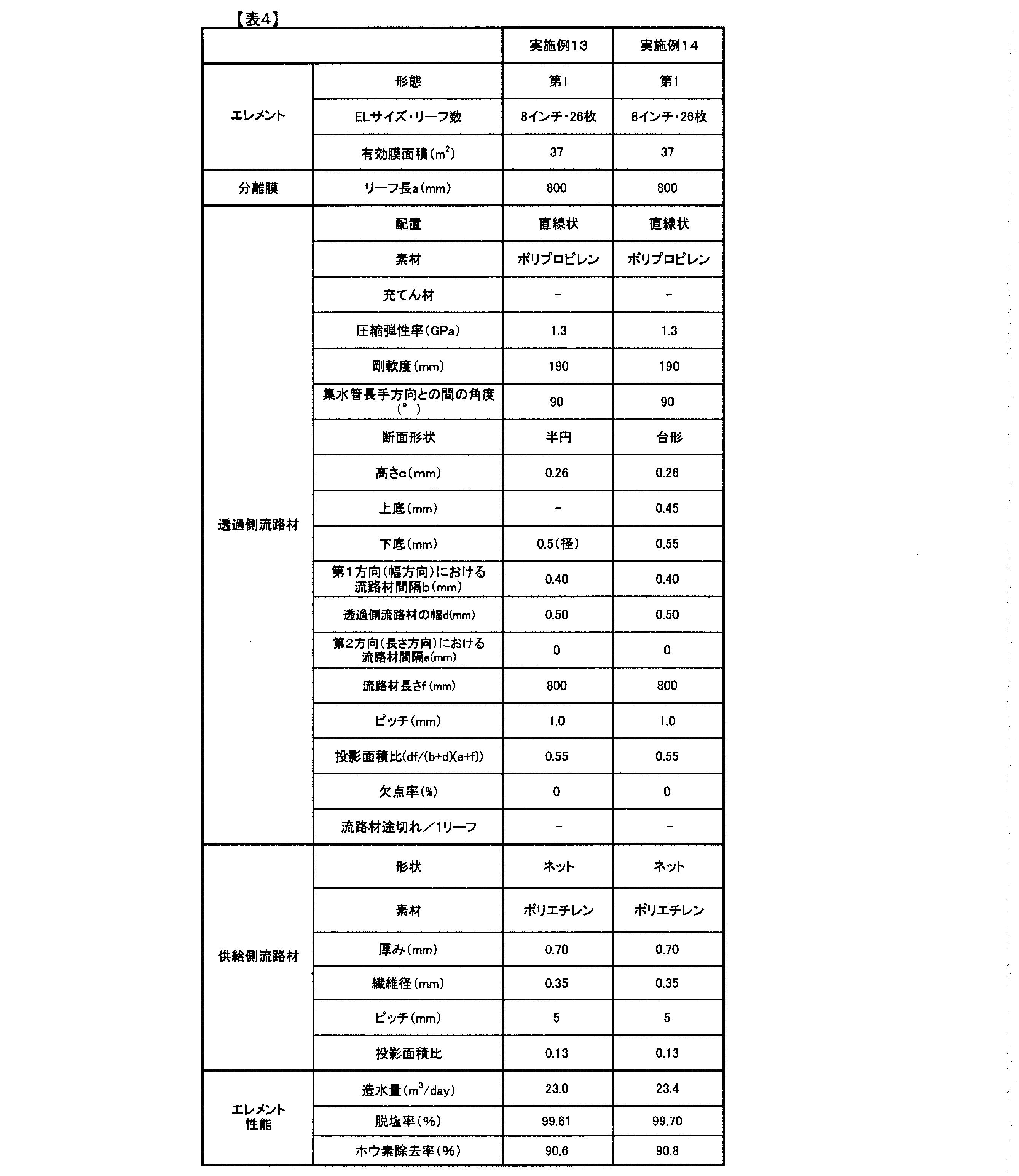


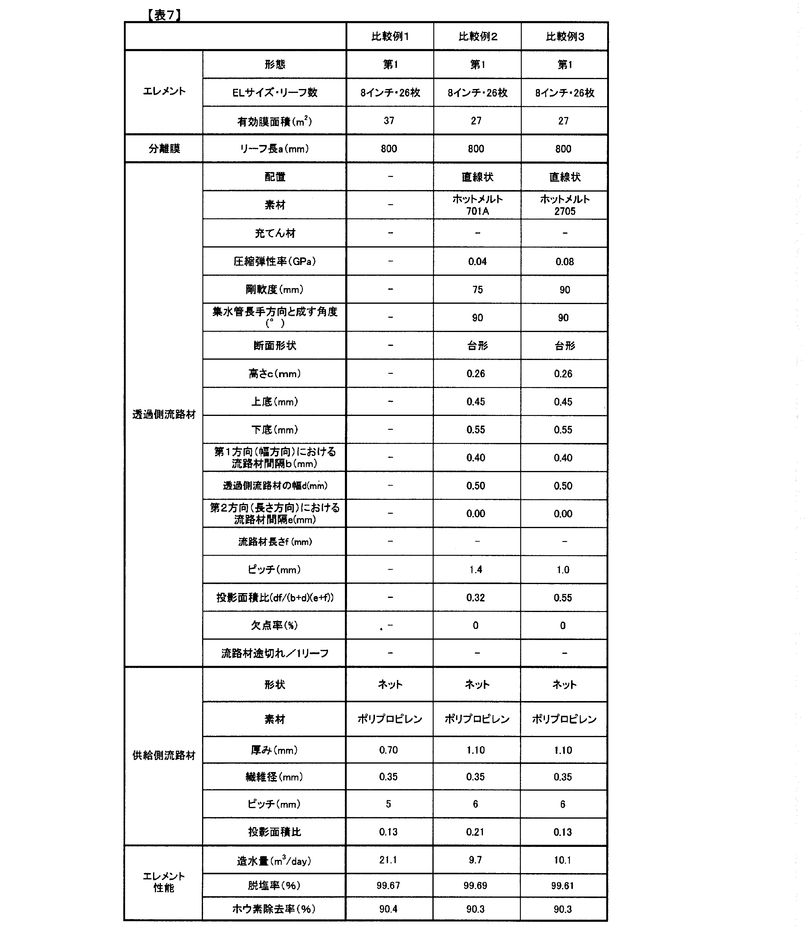
11 封筒状膜
2 分離膜本体
21 供給側の面
22 透過側の面
201 基材
202 多孔性支持層
203 分離機能層
31 透過側流路材
32 供給側流路材
4 分離膜リーフ
5 透過側流路
6 集水管
7 分離膜
71 供給側の面
72 透過側の面
82 多孔性部材
91 端板(孔無)
92 端板(孔有)
100 分離膜エレメント
a 分離膜(リーフ)長さ
b 透過側流路材の幅方向間隔
c 透過側流路材の高低差
d 透過側流路材の幅
e 透過側流路材の長さ方向の間隔
f 透過側流路材の長さ
R2 分離膜において巻回方向内側から外側に並んだ透過側流路材の先頭から最後尾までを含む領域
R3 分離膜の巻回方向外側端部において透過側流路材が設けられていない領域
L1 分離膜全体の長さ(上記長さa)
L2 領域R2の長さ
L3 領域R3の長さ
100 分離膜エレメント
100A 分離膜エレメント(第1形態)
100B 分離膜エレメント(第2形態)
100C 分離膜エレメント(第3形態)
101 原水
102 透過水
103 濃縮水
Claims (14)
- 分離膜本体と、前記分離膜本体上に固着した流路材と、を備える分離膜であって、
前記流路材の圧縮弾性率が0.1GPa以上5.0GPa以下であることを特徴とする分離膜。 - 前記分離膜の剛軟度が400mm以下であることを特徴とする請求項1記載の分離膜。
- 原水温度25℃以下かつ圧力5.5MPa以下で運転したときの、前記流路材の高さの変形率が40%以下であることを特徴とする請求項1または2に記載の分離膜。
- 前記分離膜本体は、供給側の面と透過側の面とを備え、
前記流路材は、前記透過側の面に設けられることを特徴とする請求項1~3に記載の分離膜。 - 前記流路材は、前記分離膜機能層とは異なる材料で形成されている
請求項1~4のいずれかに記載の分離膜。 - 前記流路材と前記分離膜表面との高さが30μm以上800μm以下であることを特徴とする請求項1~5のいずれかに記載の分離膜。
- 前記流路材が第1方向において前記分離膜本体上に不連続に設けられていることを特徴とする請求項1~6のいずれかに分離膜。
- 前記流路材は、前記第1方向に直交する方向において、前記分離膜本体の一端から他端まで連続状に設けられていることを特徴とする請求項1~7のいずれかに記載の分離膜。
- 隣り合う流路材の間隔が0.05mm以上5mm以下であることを特徴とする請求項1~8のいずれかに記載の分離膜。
- 前記流路材が熱可塑性樹脂で形成されていることを特徴とする請求項1~9のいずれかに記載の分離膜。
- 前記分離膜本体が、基材と、前記基材上に設けられた多孔性支持層と、前記多孔性支持層上に設けられた分離機能層とを備え
前記基材が長繊維不織布であることを特徴とする請求項1~10のいずれかに記載の分離膜。 - 前記長繊維不織布の前記多孔性支持層とは反対側の表層における繊維が、前記多孔性支持層側の表層の繊維よりも縦配向である、請求項11に記載の分離膜。
- 集水管と、請求項1~12のいずれかに記載の前記分離膜と、を備え、
前記分離膜は、前記第1方向が前記集水管の長手方向に沿うように配置され、かつ前記集水管の周囲に巻回されている分離膜エレメント。 - 少なくとも基材および分離機能層を有する分離膜本体を準備する工程、
圧縮弾性率が0.1GPa以上5.0GPa以下の材料を熱によって軟化する工程、
軟化した前記材料を、前記分離膜本体の基材側の面に配置することで、透過側流路材を形成する工程、および
前記材料を固化することで、前記分離膜本体上に前記透過側流路材を固着させる工程
を含む分離膜の製造方法。
Priority Applications (4)
| Application Number | Priority Date | Filing Date | Title |
|---|---|---|---|
| KR1020147006593A KR20140082651A (ko) | 2011-09-29 | 2012-09-28 | 분리막, 분리막 엘리먼트 및 분리막의 제조 방법 |
| CN201280048049.3A CN103842055B (zh) | 2011-09-29 | 2012-09-28 | 分离膜、分离膜元件及分离膜的制造方法 |
| US14/348,299 US20140251896A1 (en) | 2011-09-29 | 2012-09-28 | Separation membrane, separation membrane element and method for producing separation membrane |
| EP12836617.6A EP2742992A4 (en) | 2011-09-29 | 2012-09-28 | SEPARATION MEMBRANE, SEPARATION MEMBRANE ELEMENT, AND METHOD FOR PRODUCING THE SEPARATION MEMBRANE |
Applications Claiming Priority (4)
| Application Number | Priority Date | Filing Date | Title |
|---|---|---|---|
| JP2011214219 | 2011-09-29 | ||
| JP2011-214219 | 2011-09-29 | ||
| JP2011264502 | 2011-12-02 | ||
| JP2011-264502 | 2011-12-02 |
Publications (1)
| Publication Number | Publication Date |
|---|---|
| WO2013047746A1 true WO2013047746A1 (ja) | 2013-04-04 |
Family
ID=47995771
Family Applications (1)
| Application Number | Title | Priority Date | Filing Date |
|---|---|---|---|
| PCT/JP2012/075078 WO2013047746A1 (ja) | 2011-09-29 | 2012-09-28 | 分離膜、分離膜エレメントおよび分離膜の製造方法 |
Country Status (7)
| Country | Link |
|---|---|
| US (1) | US20140251896A1 (ja) |
| EP (1) | EP2742992A4 (ja) |
| JP (2) | JPWO2013047746A1 (ja) |
| KR (1) | KR20140082651A (ja) |
| CN (1) | CN103842055B (ja) |
| TW (1) | TW201318690A (ja) |
| WO (1) | WO2013047746A1 (ja) |
Cited By (13)
| Publication number | Priority date | Publication date | Assignee | Title |
|---|---|---|---|---|
| WO2014003171A1 (ja) * | 2012-06-28 | 2014-01-03 | 東レ株式会社 | 分離膜および分離膜エレメント |
| WO2014021133A1 (ja) * | 2012-07-31 | 2014-02-06 | 東レ株式会社 | 分離膜および分離膜エレメント |
| WO2015025811A1 (ja) * | 2013-08-19 | 2015-02-26 | 富士フイルム株式会社 | 酸性ガス分離モジュール |
| WO2015064720A1 (ja) * | 2013-10-30 | 2015-05-07 | 東レ株式会社 | 分離膜、シート流路材および分離膜エレメント |
| WO2015115575A1 (ja) * | 2014-01-31 | 2015-08-06 | 東レ株式会社 | 分離膜、シート流路材および分離膜エレメント |
| US20150375173A1 (en) * | 2014-06-25 | 2015-12-31 | Emd Millipore Corporation | Compact spiral-wound filter elements, modules and systems |
| WO2016159333A1 (ja) * | 2015-03-31 | 2016-10-06 | 東レ株式会社 | 分離膜 |
| US10207225B2 (en) | 2014-06-16 | 2019-02-19 | Emd Millipore Corporation | Single-pass filtration systems and processes |
| WO2019216656A1 (ko) * | 2018-05-10 | 2019-11-14 | 주식회사 엘지화학 | 역삼투막, 이의 제조방법 및 수처리 모듈 |
| US10550148B2 (en) | 2014-06-16 | 2020-02-04 | Emd Millipore Corporation | Methods for increasing the capacity of flow-through processes |
| CN112516799A (zh) * | 2020-12-18 | 2021-03-19 | 山东建筑大学 | 一种反渗透膜及其制备方法 |
| US11033839B2 (en) | 2014-08-29 | 2021-06-15 | Emd Millipore Corporation | Single pass tangential flow filtration systems and tangential flow filtration systems with recirculation of retentate |
| US11278827B2 (en) | 2014-08-29 | 2022-03-22 | Emd Millipore Corporation | Processes for filtering liquids using single pass tangential flow filtration systems and tangential flow filtration systems with recirculation of retentate |
Families Citing this family (14)
| Publication number | Priority date | Publication date | Assignee | Title |
|---|---|---|---|---|
| EP3064267A4 (en) | 2013-10-31 | 2017-07-26 | Toray Industries, Inc. | Separation membrane element |
| KR20170101212A (ko) * | 2014-12-26 | 2017-09-05 | 도레이 카부시키가이샤 | 분리막 엘리먼트 |
| WO2016201498A1 (en) * | 2015-06-15 | 2016-12-22 | Dmac Ip Pty Ltd | Water treatment system and method |
| JP2019501019A (ja) * | 2015-12-23 | 2019-01-17 | ソルベイ スペシャルティ ポリマーズ イタリー エス.ピー.エー. | シリケートを含む多孔質膜 |
| WO2018021387A1 (ja) * | 2016-07-28 | 2018-02-01 | 東レ株式会社 | 分離膜エレメント |
| JP7037306B2 (ja) | 2016-09-16 | 2022-03-16 | 日東電工株式会社 | スパイラル型膜エレメント |
| WO2020121058A2 (en) | 2018-11-16 | 2020-06-18 | Magna Imperio Systems Corp. | Spacers for ion-exchange device |
| WO2020210526A1 (en) | 2019-04-09 | 2020-10-15 | Magna Imperio Systems Corp. | Electrodialysis systems with decreased concentration gradients at high recovery rates |
| US11577202B2 (en) | 2019-06-25 | 2023-02-14 | Magna Imperio Systems Corp. | Electrodialysis process and bipolar membrane electrodialysis devices for silica removal |
| JP6767562B1 (ja) * | 2019-12-27 | 2020-10-14 | 日東電工株式会社 | 複合半透膜 |
| KR20220150911A (ko) * | 2020-03-31 | 2022-11-11 | 도레이 카부시키가이샤 | 스펀본드 부직포 |
| TWI755332B (zh) * | 2021-05-31 | 2022-02-11 | 國立高雄科技大學 | 具高滲透通量之含二氧化矽奈米顆粒之正滲透薄膜及其製備方法 |
| WO2023246740A1 (zh) * | 2022-06-21 | 2023-12-28 | 杭州苏博瑞驰科技有限公司 | 短流道膜元件及滤芯 |
| CN116834306B (zh) * | 2023-07-28 | 2024-06-14 | 苏州苏瑞膜纳米科技有限公司 | 一种多层工业滤水膜的卷膜机 |
Citations (9)
| Publication number | Priority date | Publication date | Assignee | Title |
|---|---|---|---|---|
| JPH03504820A (ja) * | 1988-04-04 | 1991-10-24 | アクア―ケム・インコーポレーテッド | スパイラル状に巻かれた逆浸透膜セル |
| JPH03249907A (ja) * | 1990-02-27 | 1991-11-07 | Toray Ind Inc | スパイラル型脱気エレメントおよびその使用方法 |
| JPH0411928B2 (ja) | 1985-12-16 | 1992-03-03 | Nippon Electric Co | |
| JPH11226366A (ja) | 1998-02-19 | 1999-08-24 | Toray Ind Inc | 流体分離膜エレメントの製造方法および装置ならびに流体分離膜エレメント |
| JP2003275545A (ja) * | 2002-03-22 | 2003-09-30 | Nitto Denko Corp | スパイラル型膜エレメント及びその製造方法 |
| JP2006247629A (ja) * | 2005-02-08 | 2006-09-21 | Nitto Denko Corp | スパイラル型膜エレメント及びその製造方法 |
| JP2006247453A (ja) | 2005-03-08 | 2006-09-21 | Toray Ind Inc | 液体分離素子、およびそれを用いた逆浸透装置、逆浸透膜処理方法 |
| JP2010099590A (ja) | 2008-10-23 | 2010-05-06 | Nitto Denko Corp | シート状複合半透膜及びその製造方法 |
| WO2011105278A1 (ja) * | 2010-02-23 | 2011-09-01 | 東レ株式会社 | 複合半透膜およびその製造方法 |
Family Cites Families (18)
| Publication number | Priority date | Publication date | Assignee | Title |
|---|---|---|---|---|
| US4390575A (en) * | 1981-12-02 | 1983-06-28 | Baxter Travenol Laboratories, Inc. | Multichanneled diffusion device |
| JP2898665B2 (ja) * | 1989-09-28 | 1999-06-02 | テルモ株式会社 | 血漿分離膜およびそれを用いた血漿分離器 |
| US5244578A (en) * | 1989-09-28 | 1993-09-14 | Terumo Kabushiki Kaisha | Blood plasma-separating membrane and blood plasma separator using the membrane |
| US5154832A (en) * | 1990-02-27 | 1992-10-13 | Toray Industries, Inc. | Spiral wound gas permeable membrane module and apparatus and method for using the same |
| US5458719A (en) * | 1993-03-24 | 1995-10-17 | Pall Corporation | Method for bonding a porous medium to a substrate |
| JPH0731857A (ja) * | 1993-07-23 | 1995-02-03 | Nitto Denko Corp | 平膜構造体 |
| JP3430783B2 (ja) * | 1996-04-11 | 2003-07-28 | 東レ株式会社 | 液体分離素子、装置および処理方法 |
| JP2000051671A (ja) * | 1998-08-06 | 2000-02-22 | Nitto Denko Corp | スパイラル型分離膜エレメント |
| EP1059114B1 (en) * | 1999-06-08 | 2005-10-12 | Nitto Denko Corporation | Liquid separation membrane module and method of producing the same |
| JP3956262B2 (ja) * | 1999-06-08 | 2007-08-08 | 日東電工株式会社 | 液体分離膜モジュール |
| JP2000350923A (ja) * | 1999-06-09 | 2000-12-19 | Toray Ind Inc | 流体分離素子およびその製造方法 |
| US6986428B2 (en) * | 2003-05-14 | 2006-01-17 | 3M Innovative Properties Company | Fluid separation membrane module |
| JP2005211790A (ja) * | 2004-01-29 | 2005-08-11 | Nitto Denko Corp | スパイラル型膜エレメント及びその逆流洗浄方法 |
| EP2439321A1 (en) * | 2006-03-31 | 2012-04-11 | Toray Industries, Inc. | Liquid separation device, flow channel material and production method thereof |
| JP2010125418A (ja) * | 2008-11-28 | 2010-06-10 | Nitto Denko Corp | シート状分離膜および分離膜エレメント |
| CN102333582B (zh) * | 2009-02-25 | 2014-08-06 | 普拉特及惠特尼火箭达因公司 | 具有减少的积垢的流体分离系统 |
| JP2011092905A (ja) * | 2009-10-30 | 2011-05-12 | Japan Gore Tex Inc | 脱気膜の製造方法、封筒状物、および該封筒状物を用いた脱気装置 |
| JP2012040487A (ja) * | 2010-08-18 | 2012-03-01 | Toray Ind Inc | 分離膜エレメント |
-
2012
- 2012-09-28 US US14/348,299 patent/US20140251896A1/en not_active Abandoned
- 2012-09-28 KR KR1020147006593A patent/KR20140082651A/ko not_active Application Discontinuation
- 2012-09-28 WO PCT/JP2012/075078 patent/WO2013047746A1/ja active Application Filing
- 2012-09-28 JP JP2012549033A patent/JPWO2013047746A1/ja active Pending
- 2012-09-28 EP EP12836617.6A patent/EP2742992A4/en not_active Withdrawn
- 2012-09-28 CN CN201280048049.3A patent/CN103842055B/zh not_active Expired - Fee Related
- 2012-09-28 TW TW101135713A patent/TW201318690A/zh unknown
-
2017
- 2017-05-12 JP JP2017095279A patent/JP2017148805A/ja active Pending
Patent Citations (9)
| Publication number | Priority date | Publication date | Assignee | Title |
|---|---|---|---|---|
| JPH0411928B2 (ja) | 1985-12-16 | 1992-03-03 | Nippon Electric Co | |
| JPH03504820A (ja) * | 1988-04-04 | 1991-10-24 | アクア―ケム・インコーポレーテッド | スパイラル状に巻かれた逆浸透膜セル |
| JPH03249907A (ja) * | 1990-02-27 | 1991-11-07 | Toray Ind Inc | スパイラル型脱気エレメントおよびその使用方法 |
| JPH11226366A (ja) | 1998-02-19 | 1999-08-24 | Toray Ind Inc | 流体分離膜エレメントの製造方法および装置ならびに流体分離膜エレメント |
| JP2003275545A (ja) * | 2002-03-22 | 2003-09-30 | Nitto Denko Corp | スパイラル型膜エレメント及びその製造方法 |
| JP2006247629A (ja) * | 2005-02-08 | 2006-09-21 | Nitto Denko Corp | スパイラル型膜エレメント及びその製造方法 |
| JP2006247453A (ja) | 2005-03-08 | 2006-09-21 | Toray Ind Inc | 液体分離素子、およびそれを用いた逆浸透装置、逆浸透膜処理方法 |
| JP2010099590A (ja) | 2008-10-23 | 2010-05-06 | Nitto Denko Corp | シート状複合半透膜及びその製造方法 |
| WO2011105278A1 (ja) * | 2010-02-23 | 2011-09-01 | 東レ株式会社 | 複合半透膜およびその製造方法 |
Non-Patent Citations (1)
| Title |
|---|
| OFFICE OF SALINE WATER, RESEARCH AND DEVELOPMENT PROGRESS REPORT, 1968 |
Cited By (41)
| Publication number | Priority date | Publication date | Assignee | Title |
|---|---|---|---|---|
| WO2014003171A1 (ja) * | 2012-06-28 | 2014-01-03 | 東レ株式会社 | 分離膜および分離膜エレメント |
| JPWO2014003171A1 (ja) * | 2012-06-28 | 2016-06-02 | 東レ株式会社 | 分離膜および分離膜エレメント |
| WO2014021133A1 (ja) * | 2012-07-31 | 2014-02-06 | 東レ株式会社 | 分離膜および分離膜エレメント |
| JP2016026860A (ja) * | 2013-08-19 | 2016-02-18 | 富士フイルム株式会社 | 酸性ガス分離モジュール |
| WO2015025811A1 (ja) * | 2013-08-19 | 2015-02-26 | 富士フイルム株式会社 | 酸性ガス分離モジュール |
| KR102254401B1 (ko) | 2013-10-30 | 2021-05-24 | 도레이 카부시키가이샤 | 분리막, 시트 유로재 및 분리막 엘리먼트 |
| JP5888439B2 (ja) * | 2013-10-30 | 2016-03-22 | 東レ株式会社 | 分離膜、シート流路材および分離膜エレメント |
| KR20160075543A (ko) * | 2013-10-30 | 2016-06-29 | 도레이 카부시키가이샤 | 분리막, 시트 유로재 및 분리막 엘리먼트 |
| JPWO2015064720A1 (ja) * | 2013-10-30 | 2017-03-09 | 東レ株式会社 | 分離膜、シート流路材および分離膜エレメント |
| WO2015064720A1 (ja) * | 2013-10-30 | 2015-05-07 | 東レ株式会社 | 分離膜、シート流路材および分離膜エレメント |
| EP3064266A4 (en) * | 2013-10-30 | 2017-06-28 | Toray Industries, Inc. | Separation membrane, sheet flow path material, and separation membrane element |
| US9802160B2 (en) | 2013-10-30 | 2017-10-31 | Toray Industries, Inc. | Separation membrane, sheet flow path material, and separation membrane element |
| KR102283221B1 (ko) * | 2014-01-31 | 2021-07-29 | 도레이 카부시키가이샤 | 분리막, 시트 유로재 및 분리막 엘리먼트 |
| WO2015115575A1 (ja) * | 2014-01-31 | 2015-08-06 | 東レ株式会社 | 分離膜、シート流路材および分離膜エレメント |
| CN105939776A (zh) * | 2014-01-31 | 2016-09-14 | 东丽株式会社 | 分离膜、片材流路部件及分离膜元件 |
| KR20160108392A (ko) * | 2014-01-31 | 2016-09-19 | 도레이 카부시키가이샤 | 분리막, 시트 유로재 및 분리막 엘리먼트 |
| US10159942B2 (en) | 2014-01-31 | 2018-12-25 | Toray Industries, Inc. | Separation membrane, sheet channel material, and separation membrane element |
| JPWO2015115575A1 (ja) * | 2014-01-31 | 2017-03-23 | 東レ株式会社 | 分離膜、シート流路材および分離膜エレメント |
| US10207225B2 (en) | 2014-06-16 | 2019-02-19 | Emd Millipore Corporation | Single-pass filtration systems and processes |
| US11040310B2 (en) | 2014-06-16 | 2021-06-22 | Emd Millipore Corporation | Single-pass filtration systems and processes |
| US11617988B2 (en) | 2014-06-16 | 2023-04-04 | Emd Millipore Corporation | Single-pass filtration systems and processes |
| US10550148B2 (en) | 2014-06-16 | 2020-02-04 | Emd Millipore Corporation | Methods for increasing the capacity of flow-through processes |
| US11986772B2 (en) | 2014-06-25 | 2024-05-21 | Emd Millipore Corporation | Compact spiral-wound filter elements, modules and systems |
| US11311841B2 (en) | 2014-06-25 | 2022-04-26 | Emd Millipore Corp. | Compact spiral-wound filter elements, modules and systems |
| US20150375173A1 (en) * | 2014-06-25 | 2015-12-31 | Emd Millipore Corporation | Compact spiral-wound filter elements, modules and systems |
| US11278827B2 (en) | 2014-08-29 | 2022-03-22 | Emd Millipore Corporation | Processes for filtering liquids using single pass tangential flow filtration systems and tangential flow filtration systems with recirculation of retentate |
| US11033839B2 (en) | 2014-08-29 | 2021-06-15 | Emd Millipore Corporation | Single pass tangential flow filtration systems and tangential flow filtration systems with recirculation of retentate |
| US11679349B2 (en) | 2014-08-29 | 2023-06-20 | Emd Millipore Corporation | Single pass tangential flow filtration systems and tangential flow filtration systems with recirculation of retentate |
| US11103836B2 (en) | 2015-03-31 | 2021-08-31 | Toray Industries, Inc. | Separation membrane |
| WO2016159333A1 (ja) * | 2015-03-31 | 2016-10-06 | 東レ株式会社 | 分離膜 |
| US10639595B2 (en) | 2015-03-31 | 2020-05-05 | Toray Industries, Inc. | Separation membrane |
| KR102337389B1 (ko) | 2015-03-31 | 2021-12-10 | 도레이 카부시키가이샤 | 분리막 |
| KR20170131474A (ko) * | 2015-03-31 | 2017-11-29 | 도레이 카부시키가이샤 | 분리막 |
| JPWO2016159333A1 (ja) * | 2015-03-31 | 2017-04-27 | 東レ株式会社 | 分離膜 |
| CN111712317A (zh) * | 2018-05-10 | 2020-09-25 | 株式会社Lg化学 | 反渗透膜、其制造方法及水处理模块 |
| KR102212128B1 (ko) * | 2018-05-10 | 2021-02-17 | 주식회사 엘지화학 | 역삼투막, 이의 제조방법 및 수처리 모듈 |
| KR20190129296A (ko) * | 2018-05-10 | 2019-11-20 | 주식회사 엘지화학 | 역삼투막, 이의 제조방법 및 수처리 모듈 |
| CN111712317B (zh) * | 2018-05-10 | 2022-10-11 | 株式会社Lg化学 | 反渗透膜、其制造方法及水处理模块 |
| WO2019216656A1 (ko) * | 2018-05-10 | 2019-11-14 | 주식회사 엘지화학 | 역삼투막, 이의 제조방법 및 수처리 모듈 |
| US11883785B2 (en) | 2018-05-10 | 2024-01-30 | Lg Chem, Ltd. | Reverse osmosis membrane, manufacturing method therefor, and water treatment module |
| CN112516799A (zh) * | 2020-12-18 | 2021-03-19 | 山东建筑大学 | 一种反渗透膜及其制备方法 |
Also Published As
| Publication number | Publication date |
|---|---|
| JPWO2013047746A1 (ja) | 2015-03-26 |
| CN103842055A (zh) | 2014-06-04 |
| TW201318690A (zh) | 2013-05-16 |
| JP2017148805A (ja) | 2017-08-31 |
| CN103842055B (zh) | 2016-08-17 |
| EP2742992A1 (en) | 2014-06-18 |
| KR20140082651A (ko) | 2014-07-02 |
| EP2742992A4 (en) | 2014-12-10 |
| US20140251896A1 (en) | 2014-09-11 |
Similar Documents
| Publication | Publication Date | Title |
|---|---|---|
| WO2013047746A1 (ja) | 分離膜、分離膜エレメントおよび分離膜の製造方法 | |
| JP6136269B2 (ja) | 水処理用分離膜エレメント | |
| JP6111668B2 (ja) | 分離膜エレメント、および分離膜エレメントの製造方法 | |
| JP6485044B2 (ja) | 分離膜エレメント | |
| JP6179402B2 (ja) | 分離膜エレメント | |
| JP6015650B2 (ja) | 分離膜および分離膜エレメント | |
| WO2015016253A1 (ja) | 分離膜エレメント | |
| JP6179403B2 (ja) | 分離膜および分離膜エレメント | |
| JP2015071159A (ja) | 分離膜エレメント | |
| WO2014208602A1 (ja) | 分離膜エレメント | |
| JP2014064973A (ja) | 分離膜および分離膜エレメント | |
| JP2015006661A (ja) | 分離膜エレメント | |
| JP2014140837A (ja) | 分離膜エレメント | |
| JP2015142894A (ja) | 分離膜エレメント | |
| JP2016068081A (ja) | 分離膜エレメント | |
| JP2014193460A (ja) | 分離膜および分離膜エレメント | |
| JP2014193459A (ja) | 分離膜エレメント | |
| JP2015142911A (ja) | 分離膜および分離膜エレメント | |
| JP2014140840A (ja) | 分離膜エレメント | |
| JP2015085322A (ja) | 分離膜エレメント | |
| JP2015091574A (ja) | 分離膜エレメント | |
| JP2017013055A (ja) | 分離膜エレメント | |
| JP2015127051A (ja) | 分離膜エレメント |
Legal Events
| Date | Code | Title | Description |
|---|---|---|---|
| ENP | Entry into the national phase |
Ref document number: 2012549033 Country of ref document: JP Kind code of ref document: A |
|
| 121 | Ep: the epo has been informed by wipo that ep was designated in this application |
Ref document number: 12836617 Country of ref document: EP Kind code of ref document: A1 |
|
| WWE | Wipo information: entry into national phase |
Ref document number: 2012836617 Country of ref document: EP |
|
| ENP | Entry into the national phase |
Ref document number: 20147006593 Country of ref document: KR Kind code of ref document: A |
|
| WWE | Wipo information: entry into national phase |
Ref document number: 14348299 Country of ref document: US |
|
| NENP | Non-entry into the national phase |
Ref country code: DE |