WO2013031817A1 - 不活性ガス精製方法 - Google Patents
不活性ガス精製方法 Download PDFInfo
- Publication number
- WO2013031817A1 WO2013031817A1 PCT/JP2012/071809 JP2012071809W WO2013031817A1 WO 2013031817 A1 WO2013031817 A1 WO 2013031817A1 JP 2012071809 W JP2012071809 W JP 2012071809W WO 2013031817 A1 WO2013031817 A1 WO 2013031817A1
- Authority
- WO
- WIPO (PCT)
- Prior art keywords
- inert gas
- catalyst
- hydrogen
- carbon monoxide
- oxygen
- Prior art date
- Legal status (The legal status is an assumption and is not a legal conclusion. Google has not performed a legal analysis and makes no representation as to the accuracy of the status listed.)
- Ceased
Links
Images




Classifications
-
- B—PERFORMING OPERATIONS; TRANSPORTING
- B01—PHYSICAL OR CHEMICAL PROCESSES OR APPARATUS IN GENERAL
- B01D—SEPARATION
- B01D53/00—Separation of gases or vapours; Recovering vapours of volatile solvents from gases; Chemical or biological purification of waste gases, e.g. engine exhaust gases, smoke, fumes, flue gases, aerosols
- B01D53/02—Separation of gases or vapours; Recovering vapours of volatile solvents from gases; Chemical or biological purification of waste gases, e.g. engine exhaust gases, smoke, fumes, flue gases, aerosols by adsorption, e.g. preparative gas chromatography
- B01D53/04—Separation of gases or vapours; Recovering vapours of volatile solvents from gases; Chemical or biological purification of waste gases, e.g. engine exhaust gases, smoke, fumes, flue gases, aerosols by adsorption, e.g. preparative gas chromatography with stationary adsorbents
-
- B—PERFORMING OPERATIONS; TRANSPORTING
- B01—PHYSICAL OR CHEMICAL PROCESSES OR APPARATUS IN GENERAL
- B01J—CHEMICAL OR PHYSICAL PROCESSES, e.g. CATALYSIS OR COLLOID CHEMISTRY; THEIR RELEVANT APPARATUS
- B01J23/00—Catalysts comprising metals or metal oxides or hydroxides, not provided for in group B01J21/00
- B01J23/38—Catalysts comprising metals or metal oxides or hydroxides, not provided for in group B01J21/00 of noble metals
- B01J23/40—Catalysts comprising metals or metal oxides or hydroxides, not provided for in group B01J21/00 of noble metals of the platinum group metals
- B01J23/44—Palladium
-
- C—CHEMISTRY; METALLURGY
- C01—INORGANIC CHEMISTRY
- C01B—NON-METALLIC ELEMENTS; COMPOUNDS THEREOF; METALLOIDS OR COMPOUNDS THEREOF NOT COVERED BY SUBCLASS C01C
- C01B21/00—Nitrogen; Compounds thereof
- C01B21/04—Purification or separation of nitrogen
- C01B21/0405—Purification or separation processes
- C01B21/0494—Combined chemical and physical processing
-
- C—CHEMISTRY; METALLURGY
- C01—INORGANIC CHEMISTRY
- C01B—NON-METALLIC ELEMENTS; COMPOUNDS THEREOF; METALLOIDS OR COMPOUNDS THEREOF NOT COVERED BY SUBCLASS C01C
- C01B23/00—Noble gases; Compounds thereof
- C01B23/001—Purification or separation processes of noble gases
- C01B23/0094—Combined chemical and physical processing
-
- B—PERFORMING OPERATIONS; TRANSPORTING
- B01—PHYSICAL OR CHEMICAL PROCESSES OR APPARATUS IN GENERAL
- B01D—SEPARATION
- B01D2253/00—Adsorbents used in seperation treatment of gases and vapours
- B01D2253/10—Inorganic adsorbents
- B01D2253/102—Carbon
-
- B—PERFORMING OPERATIONS; TRANSPORTING
- B01—PHYSICAL OR CHEMICAL PROCESSES OR APPARATUS IN GENERAL
- B01D—SEPARATION
- B01D2253/00—Adsorbents used in seperation treatment of gases and vapours
- B01D2253/10—Inorganic adsorbents
- B01D2253/104—Alumina
-
- B—PERFORMING OPERATIONS; TRANSPORTING
- B01—PHYSICAL OR CHEMICAL PROCESSES OR APPARATUS IN GENERAL
- B01D—SEPARATION
- B01D2253/00—Adsorbents used in seperation treatment of gases and vapours
- B01D2253/10—Inorganic adsorbents
- B01D2253/106—Silica or silicates
- B01D2253/108—Zeolites
-
- B—PERFORMING OPERATIONS; TRANSPORTING
- B01—PHYSICAL OR CHEMICAL PROCESSES OR APPARATUS IN GENERAL
- B01D—SEPARATION
- B01D2256/00—Main component in the product gas stream after treatment
- B01D2256/18—Noble gases
-
- B—PERFORMING OPERATIONS; TRANSPORTING
- B01—PHYSICAL OR CHEMICAL PROCESSES OR APPARATUS IN GENERAL
- B01D—SEPARATION
- B01D2257/00—Components to be removed
- B01D2257/50—Carbon oxides
- B01D2257/502—Carbon monoxide
-
- B—PERFORMING OPERATIONS; TRANSPORTING
- B01—PHYSICAL OR CHEMICAL PROCESSES OR APPARATUS IN GENERAL
- B01D—SEPARATION
- B01D2257/00—Components to be removed
- B01D2257/80—Water
-
- B—PERFORMING OPERATIONS; TRANSPORTING
- B01—PHYSICAL OR CHEMICAL PROCESSES OR APPARATUS IN GENERAL
- B01J—CHEMICAL OR PHYSICAL PROCESSES, e.g. CATALYSIS OR COLLOID CHEMISTRY; THEIR RELEVANT APPARATUS
- B01J21/00—Catalysts comprising the elements, oxides, or hydroxides of magnesium, boron, aluminium, carbon, silicon, titanium, zirconium, or hafnium
- B01J21/18—Carbon
-
- B—PERFORMING OPERATIONS; TRANSPORTING
- B01—PHYSICAL OR CHEMICAL PROCESSES OR APPARATUS IN GENERAL
- B01J—CHEMICAL OR PHYSICAL PROCESSES, e.g. CATALYSIS OR COLLOID CHEMISTRY; THEIR RELEVANT APPARATUS
- B01J29/00—Catalysts comprising molecular sieves
- B01J29/04—Catalysts comprising molecular sieves having base-exchange properties, e.g. crystalline zeolites
- B01J29/041—Mesoporous materials having base exchange properties, e.g. Si/Al-MCM-41
- B01J29/042—Mesoporous materials having base exchange properties, e.g. Si/Al-MCM-41 containing iron group metals, noble metals or copper
- B01J29/043—Noble metals
-
- C—CHEMISTRY; METALLURGY
- C01—INORGANIC CHEMISTRY
- C01B—NON-METALLIC ELEMENTS; COMPOUNDS THEREOF; METALLOIDS OR COMPOUNDS THEREOF NOT COVERED BY SUBCLASS C01C
- C01B2210/00—Purification or separation of specific gases
- C01B2210/0001—Separation or purification processing
- C01B2210/0003—Chemical processing
- C01B2210/0004—Chemical processing by oxidation
-
- C—CHEMISTRY; METALLURGY
- C01—INORGANIC CHEMISTRY
- C01B—NON-METALLIC ELEMENTS; COMPOUNDS THEREOF; METALLOIDS OR COMPOUNDS THEREOF NOT COVERED BY SUBCLASS C01C
- C01B2210/00—Purification or separation of specific gases
- C01B2210/0001—Separation or purification processing
- C01B2210/0009—Physical processing
- C01B2210/0014—Physical processing by adsorption in solids
-
- C—CHEMISTRY; METALLURGY
- C01—INORGANIC CHEMISTRY
- C01B—NON-METALLIC ELEMENTS; COMPOUNDS THEREOF; METALLOIDS OR COMPOUNDS THEREOF NOT COVERED BY SUBCLASS C01C
- C01B2210/00—Purification or separation of specific gases
- C01B2210/0001—Separation or purification processing
- C01B2210/0009—Physical processing
- C01B2210/0014—Physical processing by adsorption in solids
- C01B2210/0015—Physical processing by adsorption in solids characterised by the adsorbent
- C01B2210/0017—Carbon-based materials
-
- C—CHEMISTRY; METALLURGY
- C01—INORGANIC CHEMISTRY
- C01B—NON-METALLIC ELEMENTS; COMPOUNDS THEREOF; METALLOIDS OR COMPOUNDS THEREOF NOT COVERED BY SUBCLASS C01C
- C01B2210/00—Purification or separation of specific gases
- C01B2210/0001—Separation or purification processing
- C01B2210/0009—Physical processing
- C01B2210/0014—Physical processing by adsorption in solids
- C01B2210/0015—Physical processing by adsorption in solids characterised by the adsorbent
- C01B2210/0018—Zeolites
-
- C—CHEMISTRY; METALLURGY
- C01—INORGANIC CHEMISTRY
- C01B—NON-METALLIC ELEMENTS; COMPOUNDS THEREOF; METALLOIDS OR COMPOUNDS THEREOF NOT COVERED BY SUBCLASS C01C
- C01B2210/00—Purification or separation of specific gases
- C01B2210/0029—Obtaining noble gases
- C01B2210/0031—Helium
-
- C—CHEMISTRY; METALLURGY
- C01—INORGANIC CHEMISTRY
- C01B—NON-METALLIC ELEMENTS; COMPOUNDS THEREOF; METALLOIDS OR COMPOUNDS THEREOF NOT COVERED BY SUBCLASS C01C
- C01B2210/00—Purification or separation of specific gases
- C01B2210/0029—Obtaining noble gases
- C01B2210/0032—Neon
-
- C—CHEMISTRY; METALLURGY
- C01—INORGANIC CHEMISTRY
- C01B—NON-METALLIC ELEMENTS; COMPOUNDS THEREOF; METALLOIDS OR COMPOUNDS THEREOF NOT COVERED BY SUBCLASS C01C
- C01B2210/00—Purification or separation of specific gases
- C01B2210/0029—Obtaining noble gases
- C01B2210/0034—Argon
-
- C—CHEMISTRY; METALLURGY
- C01—INORGANIC CHEMISTRY
- C01B—NON-METALLIC ELEMENTS; COMPOUNDS THEREOF; METALLOIDS OR COMPOUNDS THEREOF NOT COVERED BY SUBCLASS C01C
- C01B2210/00—Purification or separation of specific gases
- C01B2210/0029—Obtaining noble gases
- C01B2210/0037—Xenon
-
- C—CHEMISTRY; METALLURGY
- C01—INORGANIC CHEMISTRY
- C01B—NON-METALLIC ELEMENTS; COMPOUNDS THEREOF; METALLOIDS OR COMPOUNDS THEREOF NOT COVERED BY SUBCLASS C01C
- C01B2210/00—Purification or separation of specific gases
- C01B2210/0043—Impurity removed
- C01B2210/005—Carbon monoxide
-
- C—CHEMISTRY; METALLURGY
- C01—INORGANIC CHEMISTRY
- C01B—NON-METALLIC ELEMENTS; COMPOUNDS THEREOF; METALLOIDS OR COMPOUNDS THEREOF NOT COVERED BY SUBCLASS C01C
- C01B2210/00—Purification or separation of specific gases
- C01B2210/0043—Impurity removed
- C01B2210/0053—Hydrogen
-
- C—CHEMISTRY; METALLURGY
- C01—INORGANIC CHEMISTRY
- C01B—NON-METALLIC ELEMENTS; COMPOUNDS THEREOF; METALLOIDS OR COMPOUNDS THEREOF NOT COVERED BY SUBCLASS C01C
- C01B2210/00—Purification or separation of specific gases
- C01B2210/0043—Impurity removed
- C01B2210/0062—Water
-
- Y—GENERAL TAGGING OF NEW TECHNOLOGICAL DEVELOPMENTS; GENERAL TAGGING OF CROSS-SECTIONAL TECHNOLOGIES SPANNING OVER SEVERAL SECTIONS OF THE IPC; TECHNICAL SUBJECTS COVERED BY FORMER USPC CROSS-REFERENCE ART COLLECTIONS [XRACs] AND DIGESTS
- Y02—TECHNOLOGIES OR APPLICATIONS FOR MITIGATION OR ADAPTATION AGAINST CLIMATE CHANGE
- Y02C—CAPTURE, STORAGE, SEQUESTRATION OR DISPOSAL OF GREENHOUSE GASES [GHG]
- Y02C20/00—Capture or disposal of greenhouse gases
- Y02C20/40—Capture or disposal of greenhouse gases of CO2
-
- Y—GENERAL TAGGING OF NEW TECHNOLOGICAL DEVELOPMENTS; GENERAL TAGGING OF CROSS-SECTIONAL TECHNOLOGIES SPANNING OVER SEVERAL SECTIONS OF THE IPC; TECHNICAL SUBJECTS COVERED BY FORMER USPC CROSS-REFERENCE ART COLLECTIONS [XRACs] AND DIGESTS
- Y02—TECHNOLOGIES OR APPLICATIONS FOR MITIGATION OR ADAPTATION AGAINST CLIMATE CHANGE
- Y02P—CLIMATE CHANGE MITIGATION TECHNOLOGIES IN THE PRODUCTION OR PROCESSING OF GOODS
- Y02P20/00—Technologies relating to chemical industry
- Y02P20/151—Reduction of greenhouse gas [GHG] emissions, e.g. CO2
Definitions
- the present invention relates to an inert gas purification method for reusing an inert gas used in preventing oxidation or nitriding.
- an inert gas such as nitrogen or argon is used to prevent oxidation or nitridation.
- an inert gas such as nitrogen or argon is used to prevent oxidation or nitridation.
- Patent Document 1 discloses an argon purification method and an argon purification apparatus for purifying argon as an inert gas.
- each reducing gas is oxidized by performing a three-step catalytic reaction in which oxygen is added to an argon gas containing a reducing gas such as carbon monoxide or hydrogen.
- a reducing gas such as carbon monoxide or hydrogen.
- carbon monoxide is oxidized by adding oxygen to an argon gas containing carbon monoxide and hydrogen in the first catalyst tower, and then the second and third catalyst towers.
- hydrogen is oxidized by adding oxygen to remove carbon dioxide and moisture, which are reaction products generated in these catalyst towers, in an adsorption tower in the subsequent stage.
- an object of the present invention is to provide an inert gas purification method capable of efficiently purifying an inert gas.
- the present invention provides the following methods.
- the present invention provides an inert gas purification method for purifying an inert gas containing hydrogen and carbon monoxide, wherein oxygen is added to the inert gas and hydrogen is converted into water by a reaction using a catalyst.
- an inert gas refining method comprising the steps of: (1).
- the first aspect of the present invention is an inert gas purification method for purifying an inert gas containing hydrogen and carbon monoxide, A first step of adding oxygen to the inert gas and converting hydrogen into water by a reaction using a catalyst; A second step of removing the carbon monoxide and the water from the inert gas by an adsorbent after the first step; It is the inert gas purification method characterized by including.
- the temperature of the catalyst is preferably in the range of 135 to 200 ° C. in the first step.
- the concentration of the oxygen added to the inert gas in the first step is preferably 1 vol% or less.
- the catalyst has palladium supported on alumina.
- the adsorbent is preferably composed of at least one of zeolite, alumina, and activated carbon.
- the method of the present invention of the above (1) to (5) includes a sub-process for measuring the hydrogen concentration contained in the inert gas containing hydrogen and carbon monoxide before the first process, and is added in the first process. It is preferable that the amount of oxygen to be performed is a half of the hydrogen concentration measured in the sub-process.
- the catalyst is preferably a catalyst in which platinum is supported on alumina.
- the above-described methods (1) to (7) of the present invention include: Before the first step, including a sub-step of measuring a hydrogen concentration contained in an inert gas containing hydrogen and carbon monoxide, The amount of oxygen added in the first step is 1 ⁇ 2 to 1 of the hydrogen concentration measured in the sub-step, and the concentration of oxygen added to the inert gas is 1 vol% or less.
- the catalyst is either a catalyst in which palladium is supported on alumina or a catalyst in which platinum is supported on alumina. It is also preferable that the temperature of the catalyst is controlled within the range of 135 to 200 ° C. It is also preferable that the amount of oxygen added in the first step is a half of the hydrogen concentration measured in the sub-step.
- the above-described methods (1) to (8) of the present invention include:
- the first step is preferably composed of the following steps (a) to (b).
- the inert gas is preferably argon.
- a first step of adding oxygen to an inert gas and making hydrogen into water by a reaction using a catalyst and after the first step, carbon monoxide from the inert gas by an adsorbent, Including a second step of removing water and, if necessary, carbon dioxide, selectively oxidizing hydrogen, which is a difficult-to-adsorb component, into water, which is a readily-adsorbing component, and then easily-adsorbing
- the components carbon monoxide and water can be easily adsorbed and removed.
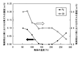
- FIG. 6 is a graph showing the concentrations of hydrogen and carbon monoxide contained in the raw material gas discharged from the catalyst tower when the temperature of the catalyst is changed in the range of 50 to 280 ° C. in the experiment of Example 1-1. is there.
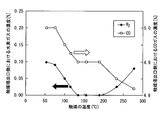
- FIG. 5 is a graph showing the concentrations of hydrogen and carbon monoxide contained in the raw material gas discharged from the catalyst tower when the temperature of the catalyst is changed in the range of 50 to 280 ° C. in the experiment No. 1-2 in the example. is there.
- FIG. 6 is a graph showing the concentrations of hydrogen and carbon monoxide contained in the raw material gas discharged from the catalyst tower when the temperature of the catalyst is changed in the range of 50 to 280 ° C. in the experiment No. 1-2 in the example. is there.
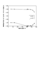
- FIG. 6 is a diagram showing the concentrations of hydrogen and carbon monoxide contained in the raw material gas discharged from the catalyst tower when the temperature of the catalyst is changed in the range of 30 to 280 ° C. in the second experiment of the example.
- FIG. 6 is a diagram showing the concentrations of hydrogen and carbon monoxide contained in the raw material gas discharged from the catalyst tower when the temperature of the catalyst is changed in the range of 30 to 400 ° C. in the third experiment of the example.
- FIG. 6 is a diagram showing the concentrations of hydrogen and carbon monoxide contained in the raw material gas discharged from the catalyst tower when the temperature of the catalyst is changed in the range of 30 to 280 ° C. in the fourth experiment of the example.
- FIG. 1 is a diagram showing a schematic configuration of an inert gas purifying apparatus according to an embodiment of the present invention.
- an inert gas purification apparatus 10 includes a buffer tank 11, a catalyst tower 13, a first gas transport line 14, a hydrogen concentration analyzer 15, and an oxygen supply line 16. And a heat exchanger 18, a second gas transport line 21, an adsorption separation unit 23, and a gas discharge line 24.
- the buffer tank 11 is a raw material gas (hereinafter referred to as “raw material”) that is an inert gas containing carbon monoxide and hydrogen (more specifically, exhaust gas from a heating furnace (not shown) that melts ceramics, metals, etc.). Gas A ”) is stored in the tank.
- the buffer tank 11 is connected to the first gas transport line 14.
- the source gas is not particularly limited as long as it is an inert gas containing carbon monoxide and hydrogen.
- the raw material gas A is preferably a gas substantially consisting of carbon monoxide, hydrogen, and argon gas.
- the gas may be composed of only carbon monoxide, hydrogen, and at least one inert gas.
- the source gas A is also preferably a gas not containing carbon dioxide.
- the catalyst tower 13 is connected to the buffer tank 11 via the first gas transport line 14.
- the catalyst tower 13 is provided in a portion of the first gas transport line 14 after passing through the heat exchanger 18 once.
- the catalyst tower 13 is connected to one end of the second gas transport line 21.
- the raw material gas A to which oxygen is added is transported to the catalyst tower 13 through the first gas transport line 14.
- water is generated by reacting hydrogen contained in the raw material gas A and added oxygen with a catalyst (catalytic reaction).
- the raw material gas A after the catalytic reaction is once cooled to about room temperature (for example, 25 ° C.) and then introduced into the adsorption separation unit 23.
- any catalyst that can oxidize hydrogen can be used without any particular problem.
- a catalyst for example, a catalyst in which at least one of platinum, palladium, rhodium, and ruthenium is supported on a carrier such as alumina, silica, and alumina silicate is preferable. It is particularly preferable to use alumina or palladium.
- a catalyst capable of oxidizing hydrogen generally oxidizes carbon monoxide. Therefore, in order to efficiently oxidize hydrogen, the temperature of the catalyst tower 13 is preferably controlled from the viewpoint of suppressing the oxidation of carbon monoxide.
- the temperature can be selected as required. In order to avoid the suppression of hydrogen oxidation due to the formation of carbon dioxide from carbon monoxide, it is preferably set to 200 ° C. or less, although it depends on the conditions. When oxygen is added at a high concentration, for example, when 1.5 to 2.5 vol% oxygen is added, the temperature tends to increase. Therefore, the upper limit may be set to 300 ° C. or less, but it is preferable to take measures against temperature. In terms of promoting hydrogen oxidation, the temperature is preferably 70 ° C.
- the temperature of the catalyst layer can be confirmed with a thermometer or the like such as a thermocouple, and the temperature can be controlled with a heater or the like controlled by a temperature controller. Particularly preferably, the temperature is in the range of 160-200 ° C.
- the catalyst tower 13 may be a catalyst tower 13 equipped with a heater and a thermometer.
- the hydrogen concentration analyzer 15 measures the concentration of hydrogen contained in the source gas A flowing through the portion of the first gas transport line 14 located between the buffer tank 11 and the oxygen supply line 16.
- the hydrogen concentration analyzer 15 can send the result of the hydrogen concentration contained in the measured source gas A to the oxygen supply line 16 by means that can be arbitrarily selected.
- the oxygen supply line 16 is a branch line branched from a portion of the first gas transport line 14 located between the analysis position of the hydrogen concentration analyzer 15 and the heat exchanger 18.
- the oxygen supply line 16 is a line for adding oxygen to the source gas A transported by the first gas transport line 14.
- the oxygen supply line 16 adds oxygen, preferably oxygen having an amount of 1 ⁇ 2 of the hydrogen concentration contained in the source gas A measured by the hydrogen concentration analyzer 15 to the source gas A.
- oxygen preferably oxygen having an amount of 1 ⁇ 2 of the hydrogen concentration contained in the source gas A measured by the hydrogen concentration analyzer 15 to the source gas A.
- the amount of oxygen added can be 1%.
- the amount of oxygen added to the raw material gas A may be changed to other than the above ratio.
- An excess of hydrogen may be added.
- the amount of oxygen may be, for example, 0.5 to 1.2 times the volume of hydrogen contained in the source gas A, or may be 0.5 to 1 times the volume. It is also preferable that the volume is further 0.5 to 0.55 times.
- the amount of oxygen added to the raw material gas A is preferably 1 vol% or less with respect to the raw material gas A from the viewpoint of suppressing the temperature rise of the catalyst tower 13.
- the lower limit value of oxygen is not particularly set, but it is necessary in the present invention to be larger than 0 vol% in order to oxidize hydrogen.
- FIG. 2 is a diagram showing a schematic configuration of an inert gas purifying apparatus according to a modification of the embodiment of the present invention.
- the adsorption separation part 23 is comprised from two adsorption tanks. Both adsorption tanks may be used at the same time, or by using one of them one after another, the used tanks may be replaced and adsorption separation may be performed continuously.
- the number of adsorption tanks is not limited, and can be used without any problem as long as it is one or more.
- the amount of oxygen added to the raw material gas A is preferably 1 vol% or less.
- the raw material gas A was obtained by treating the raw material gas A with an oxygen addition amount of 1 vol% or less to suppress the temperature rise. Hydrogen remains in the gas.
- two or more catalyst tanks may be used.
- a catalyst tower 13 between the buffer tank 11 and the adsorption separation unit 23, a catalyst tower 13, a first gas transport line 14, a hydrogen concentration analyzer 15, an oxygen supply line 16, a heat exchanger 18, And a plurality of units (two in the case of FIG. 2) composed of the second gas transport lines 21 and the inert gas purifying device 30 installed in series, the raw material gas A introduced into each catalyst tower 13
- the amount of oxygen to be added is preferably 1 vol% or less.
- the heat exchanger 18 is provided in the first gas transport line 14 located at the front stage of the catalyst tower 13 and the second gas transport line 21 located at the rear stage of the catalyst tower 13.
- Thermal efficiency can be improved.
- the adsorption separation unit 23 has one end connected to the other branched end of the second gas transport line 21 and the other end connected to the gas discharge line 24.
- the second gas transport line 21 passes through the heat exchanger 18, is discharged from the catalyst tower 13, and is cooled to a temperature of about room temperature (eg, 25 ° C.) (approximately from the source gas A).
- the gas from which hydrogen has been removed is transported to the adsorption separation unit 23.
- the adsorption separation unit 23 carbon monoxide contained in the raw material gas A and water generated in the catalyst tower 13 are removed by an adsorbent.
- the purified inert gas can be taken out from the outlet side of the adsorption separation unit 23 via the gas discharge line 24.
- the amounts of carbon monoxide and hydrogen are greatly reduced compared to the raw material gas A before the treatment.
- the adsorbent used in the adsorption separation unit 23 is not particularly limited, and an adsorbent capable of adsorbing carbon monoxide and water can be used.
- the adsorbent used in the adsorption separation unit 23 it is more preferable to use an adsorbent capable of adsorbing carbon monoxide and water and capable of adsorbing a small amount of carbon dioxide.
- an adsorbent for example, at least one of zeolite, alumina, and activated carbon can be used.
- the adsorbent may have a laminated structure using two or more kinds of materials.
- One of the most suitable combinations as the adsorbent having a laminated structure is, for example, a laminate in which alumina and zeolite are sequentially laminated.
- the first step of adding oxygen to an inert gas containing hydrogen and carbon monoxide and converting hydrogen into water by a catalytic reaction and after the first step, And a second step of removing carbon monoxide, water, and, if necessary, carbon dioxide from the inert gas by the adsorbent.
- purification of an inert gas can be performed efficiently.
- the inert gas treated by the method of the present invention is not particularly limited, and can be selected from general inert gases such as argon, nitrogen, helium, neon and xenon.
- the amount of hydrogen and carbon monoxide contained in the inert gas purified by the method of the present invention can also be set arbitrarily.
- the amount of hydrogen is preferably 0.01 to 10%, more preferably 0.1 to 10%, further preferably 0.1 to 4%, and particularly preferably 0.1% to 1%. %.
- the amount of carbon monoxide is preferably 1% to 50%, more preferably 1% to 20%, still more preferably 1% to 10%, and particularly preferably 1% to 5%.
- FIG. 3 is a graph showing the results of measuring the concentrations of hydrogen and carbon monoxide contained in the raw material gas discharged from the catalyst tower when the temperature of the catalyst is changed in the range of 50 to 280 ° C. (Note that the hydrogen and carbon monoxide concentration measuring instruments used in this evaluation are not shown in FIG. 1.)
- the present invention can provide an inert gas purification method capable of efficiently purifying an inert gas as compared with a conventional inert gas purification method.
- the present invention can be applied to an inert gas purification method for reusing an inert gas used for preventing oxidation or nitriding.
Landscapes
- Chemical & Material Sciences (AREA)
- Organic Chemistry (AREA)
- Chemical Kinetics & Catalysis (AREA)
- Analytical Chemistry (AREA)
- General Chemical & Material Sciences (AREA)
- Inorganic Chemistry (AREA)
- Engineering & Computer Science (AREA)
- Oil, Petroleum & Natural Gas (AREA)
- Materials Engineering (AREA)
- Catalysts (AREA)
- Separation Of Gases By Adsorption (AREA)
Abstract
水素及び一酸化炭素を含む不活性ガスを精製する不活性ガス精製方法であって、不活性ガスに酸素を添加し、触媒を用いた反応により水素を水にする第1の工程と、第1の工程後、吸着剤により、不活性ガスから一酸化炭素及び水を除去する第2の工程と、を含む。
Description
本発明は、酸化防止や窒化防止する際に使用される不活性ガスを再利用するための不活性ガス精製方法に関する。
本願は、2011年8月31日に、日本に出願された特願2011-188788号に基づき優先権を主張し、その内容をここに援用する。
本願は、2011年8月31日に、日本に出願された特願2011-188788号に基づき優先権を主張し、その内容をここに援用する。
セラミクスや金属等を加熱する加熱炉では、酸化防止や窒化防止のために、窒素やアルゴンなどの不活性ガスが使用されている。この際、使用される不活性ガスの量は、非常に多いため、使用したガスを精製することで、不活性ガスを再利用することが望まれている。
特許文献1には、不活性ガスであるアルゴンの精製を行なうアルゴン精製方法、及びアルゴン精製装置が開示されている。この方法では、一酸化炭素や水素などの還元性ガスを含むアルゴンガスに酸素が添加される、三段階の触媒反応を行うことで、それぞれの還元性ガスの酸化を行っている。
具体的には上記特許文献1には、第1の触媒塔で一酸化炭素や水素を含むアルゴンガスに酸素を添加することにより一酸化炭素を酸化し、続いて第2及び第3の触媒塔で酸素を添加することにより水素を酸化し、これら触媒塔で生成した反応生成物である二酸化炭素と水分については後段の吸着塔で除去することが開示されている。
具体的には上記特許文献1には、第1の触媒塔で一酸化炭素や水素を含むアルゴンガスに酸素を添加することにより一酸化炭素を酸化し、続いて第2及び第3の触媒塔で酸素を添加することにより水素を酸化し、これら触媒塔で生成した反応生成物である二酸化炭素と水分については後段の吸着塔で除去することが開示されている。
しかしながら、特許文献1記載のアルゴン精製方法では、触媒塔において一酸化炭素及び水素の全量を酸素で酸化するため、非常に多くの量の酸素及び触媒が必要であり、コストが増加してしまう。
つまり、特許文献1記載のアルゴン精製方法では、不活性ガスを効率良く精製することができないという問題があった。
つまり、特許文献1記載のアルゴン精製方法では、不活性ガスを効率良く精製することができないという問題があった。
そこで、本発明は、不活性ガスを効率良く精製することの可能な不活性ガス精製方法を提供することを目的とする。
上記課題を解決するため、本発明は以下の方法を提供する。
本発明は、水素及び一酸化炭素を含む不活性ガスを精製する不活性ガス精製方法であって、前記不活性ガスに酸素を添加し、触媒を用いた反応により水素を水にする第1の工程と、前記第1の工程後、吸着剤により、前記不活性ガスから前記一酸化炭素、前記水、及び第一の工程で前記一酸化炭素の酸化により発生した二酸化炭素を除去する第2の工程と、を含むことを特徴とする不活性ガス精製方法である。
(1).すなわち、本発明の第一の態様は、水素及び一酸化炭素を含む不活性ガスを精製する不活性ガス精製方法であって、
前記不活性ガスに酸素を添加し、触媒を用いた反応により水素を水にする第1の工程と、
前記第1の工程後、吸着剤により、前記不活性ガスから前記一酸化炭素、及び前記水を除去する第2の工程と、
を含むことを特徴とする不活性ガス精製方法である。
本発明は、水素及び一酸化炭素を含む不活性ガスを精製する不活性ガス精製方法であって、前記不活性ガスに酸素を添加し、触媒を用いた反応により水素を水にする第1の工程と、前記第1の工程後、吸着剤により、前記不活性ガスから前記一酸化炭素、前記水、及び第一の工程で前記一酸化炭素の酸化により発生した二酸化炭素を除去する第2の工程と、を含むことを特徴とする不活性ガス精製方法である。
(1).すなわち、本発明の第一の態様は、水素及び一酸化炭素を含む不活性ガスを精製する不活性ガス精製方法であって、
前記不活性ガスに酸素を添加し、触媒を用いた反応により水素を水にする第1の工程と、
前記第1の工程後、吸着剤により、前記不活性ガスから前記一酸化炭素、及び前記水を除去する第2の工程と、
を含むことを特徴とする不活性ガス精製方法である。
(2).上記本発明の方法は、前記第1の工程において、前記触媒の温度が、135~200℃の範囲内であることが好ましい。
(3).(1)や(2)に記載される上記本発明の方法は、前記第1の工程において、前記不活性ガスに添加された前記酸素の濃度が、1vol%以下であることが好ましい。
(4).上記(1)~(3)に記載される上記本発明の方法は、前記触媒が、アルミナにパラジウムが坦持されていることが好ましい。
(5).上記(1)~(4)の本発明の方法は、前記吸着剤が、ゼオライト、アルミナ、活性炭のうち、少なくとも1種よりなることが好ましい。
(6).上記(1)~(5)の本発明の方法は、第1工程の前に、水素及び一酸化炭素を含む不活性ガスに含まれる水素濃度を測定するサブ工程を含み、第1工程で添加される酸素の量が、前記サブ工程で測定された水素濃度の1/2の量であることが好ましい。
(5).上記(1)~(4)の本発明の方法は、前記吸着剤が、ゼオライト、アルミナ、活性炭のうち、少なくとも1種よりなることが好ましい。
(6).上記(1)~(5)の本発明の方法は、第1工程の前に、水素及び一酸化炭素を含む不活性ガスに含まれる水素濃度を測定するサブ工程を含み、第1工程で添加される酸素の量が、前記サブ工程で測定された水素濃度の1/2の量であることが好ましい。
(7).上記(1)~(3)、(5)~(6)の本発明の方法は、前記触媒が、アルミナに白金を担持させた触媒であることも好ましい。
(8).上記(1)~(7)の本発明の方法は、
第1工程の前に、水素及び一酸化炭素を含む不活性ガスに含まれる水素濃度を測定するサブ工程を含み、
第1工程で添加された酸素の量が、前記サブ工程で測定された水素濃度の1/2~1の量であり、かつ前記不活性ガスに添加された酸素の濃度が、1vol%以下であり、
前記触媒が、アルミナにパラジウムが坦持されている触媒及びアルミナに白金が坦持されている触媒のどちらかであり、
前記触媒の温度が、135~200℃の範囲内にコントロールされることも好ましい。上記第1工程で添加される酸素の量は、前記サブ工程で測定された水素濃度の1/2の量であることも好ましい。
(8).上記(1)~(7)の本発明の方法は、
第1工程の前に、水素及び一酸化炭素を含む不活性ガスに含まれる水素濃度を測定するサブ工程を含み、
第1工程で添加された酸素の量が、前記サブ工程で測定された水素濃度の1/2~1の量であり、かつ前記不活性ガスに添加された酸素の濃度が、1vol%以下であり、
前記触媒が、アルミナにパラジウムが坦持されている触媒及びアルミナに白金が坦持されている触媒のどちらかであり、
前記触媒の温度が、135~200℃の範囲内にコントロールされることも好ましい。上記第1工程で添加される酸素の量は、前記サブ工程で測定された水素濃度の1/2の量であることも好ましい。
(9).上記(1)~(8)の本発明の方法は、
第1の工程が、以下の工程(a)~(b)で構成されることが好ましい。
(a):水素濃度が2vol%を超える、水素及び一酸化炭素を含む不活性ガスに、前記不活性ガスに対して1vol%以下の酸素を添加し、触媒を用いた反応により水素を水にする工程、
(b):(a)工程によって処理された、水素濃度が2vol%以下になった、水素及び一酸化炭素を含む不活性ガスに、前記不活性ガスに対して1vol%以下になるように酸素を添加し、触媒を用いた反応により水素を水にする工程。
(10)上記(1)~(9)の本発明の方法は、
第2の工程において、第一の工程で前記一酸化炭素の酸化により発生した二酸化炭素が除去されることが好ましい。
第1の工程が、以下の工程(a)~(b)で構成されることが好ましい。
(a):水素濃度が2vol%を超える、水素及び一酸化炭素を含む不活性ガスに、前記不活性ガスに対して1vol%以下の酸素を添加し、触媒を用いた反応により水素を水にする工程、
(b):(a)工程によって処理された、水素濃度が2vol%以下になった、水素及び一酸化炭素を含む不活性ガスに、前記不活性ガスに対して1vol%以下になるように酸素を添加し、触媒を用いた反応により水素を水にする工程。
(10)上記(1)~(9)の本発明の方法は、
第2の工程において、第一の工程で前記一酸化炭素の酸化により発生した二酸化炭素が除去されることが好ましい。
また、上記本発明の方法によれば、前記不活性ガスがアルゴンであることが好ましい。
本発明によれば、不活性ガスに酸素を添加し、触媒を用いた反応により水素を水にする第1の工程と、第1の工程後、吸着剤により、不活性ガスから一酸化炭素、水、及び、必要に応じて二酸化炭素、を除去する第2の工程と、を含むことにより、難吸着成分である水素を選択的に酸化させて易吸着成分である水とし、その後、易吸着成分である一酸化炭素及び水を容易に吸着除去することが可能となる。これにより、従来の不活性ガスの精製方法と比較して、不活性ガスの精製を効率よく行うことができる。
以下、本発明の好ましい実施の形態について図面を参照して説明する。しかしながら本発明はこれら例のみに限定されるものではない。特に記載の無い限り、数、位置、材料などを必要に応じて選択や追加や省略してもよい。
(実施の形態)
図1は、本発明の実施の形態に係る不活性ガス精製装置の概略構成を示す図である。
図1を参照するに、本実施の形態の不活性ガス精製装置10は、バッファタンク11と、触媒塔13と、第1のガス輸送ライン14と、水素濃度分析計15と、酸素供給ライン16と、熱交換器18と、第2のガス輸送ライン21と、吸着分離部23と、ガス排出ライン24と、を有する。
(実施の形態)
図1は、本発明の実施の形態に係る不活性ガス精製装置の概略構成を示す図である。
図1を参照するに、本実施の形態の不活性ガス精製装置10は、バッファタンク11と、触媒塔13と、第1のガス輸送ライン14と、水素濃度分析計15と、酸素供給ライン16と、熱交換器18と、第2のガス輸送ライン21と、吸着分離部23と、ガス排出ライン24と、を有する。
バッファタンク11は、一酸化炭素及び水素を含む不活性ガス(より具体的には、セラミクスや金属等を溶融する加熱炉(図示せず)からの排ガス等)である原料ガス(以下、「原料ガスA」という)が貯留されるタンクである。バッファタンク11は、第1のガス輸送ライン14と接続されている。原料ガスは一酸化炭素及び水素を含む不活性ガスである限り特に限定されない。例えば、原料ガスAは、実質的に一酸化炭素、水素及びアルゴンガスのみからなるガスであることも好ましい。一酸化炭素、水素、及び少なくとも1種の不活性ガスのみからなるガスであってもよい。また原料ガスAは、二酸化炭素を含まないガスであることも好ましい。
触媒塔13は、第1のガス輸送ライン14を介して、バッファタンク11と接続されている。触媒塔13は、第1のガス輸送ライン14のうち、熱交換器18を一度通過した後の部分に設けられている。触媒塔13は、第2のガス輸送ライン21の一端と接続されている。
触媒塔13には、第1のガス輸送ライン14により、酸素が添加された原料ガスAが輸送される。触媒塔13では、触媒により原料ガスAに含まれる水素と添加された酸素とを反応(触媒反応)させることで、水を生成する。
触媒反応後の原料ガスAは、一旦、室温(例えば、25℃)程度まで冷却された後、吸着分離部23に導入される。
触媒反応後の原料ガスAは、一旦、室温(例えば、25℃)程度まで冷却された後、吸着分離部23に導入される。
触媒塔13で使用する触媒としては、水素を酸化することが可能な触媒であれば特に問題なく使用できる。
具体的には、上記触媒としては、例えば、アルミナ、シリカ、アルミナシリケート等の担体に、白金、パラジウム、ロジウム、及びルテニウムのうち、少なくとも1種を担持させた触媒が好適である。アルミナやパラジウムを用いることが特に好ましい。
具体的には、上記触媒としては、例えば、アルミナ、シリカ、アルミナシリケート等の担体に、白金、パラジウム、ロジウム、及びルテニウムのうち、少なくとも1種を担持させた触媒が好適である。アルミナやパラジウムを用いることが特に好ましい。
また、水素を酸化できる触媒は、一般に一酸化炭素も酸化させる。したがって、水素の酸化を効率よく行う為に一酸化炭素の酸化を抑制する観点から、触媒塔13の温度は、コントロールされることが好ましい。温度は必要に応じて選択できる。一酸化炭素から二酸化炭素が形成されることにより水素の酸化が抑制されることを避ける為には、条件にもよるが、200℃以下に設定することが好ましい。酸素を高い濃度で加える時、例えば1.5~2.5vol%の酸素を加える時は、温度上昇が起こりやすい為、上限を300℃以下としてもよいが、温度対策を行うことが好ましい。また水素の酸化を促進させる点からは温度は、70℃以上が好ましく、135℃以上であることがより好ましい。よって135~200℃の範囲内に設定することがより好ましい。触媒層の温度の確認は、熱電対の様な温度計等で行うことができ、温度のコントロールは温度調節器で制御されたヒーター等で行うことができる。特に好ましくは、前記温度は160~200℃の範囲である。触媒塔13は、ヒータと温度計を搭載した触媒塔13であってもよい。
水素濃度分析計15は、第1のガス輸送ライン14のうち、バッファタンク11と酸素供給ライン16との間に位置する部分を流れる原料ガスAに含まれる水素濃度を計測する。水素濃度分析計15は、任意に選択できる手段により、計測した原料ガスAに含まれる水素濃度の結果を、酸素供給ライン16に送ることができる。
酸素供給ライン16は、第1のガス輸送ライン14のうち、水素濃度分析計15の分析位置と熱交換器18との間に位置する部分から分岐された分岐ラインである。酸素供給ライン16は、第1のガス輸送ライン14により輸送される原料ガスAに酸素を添加するためのラインである。
酸素供給ライン16は酸素を、好ましくは水素濃度分析計15により計測された原料ガスAに含まれる水素濃度の1/2の量の酸素を、原料ガスAに添加する。この比率により効率よく反応を行うことができる。例えば、原料ガスA中の水素濃度が2%の時、加える酸素の量を1%とすることができる。
なお必要に応じて、原料ガスAに添加する酸素の量は、上記の比率以外に変更しても良い。水素に対して過剰気味に加えても良い。例えば、原料ガスAに含まれる水素の体積に対して、酸素の量は、例えば、0.5~1.2倍の体積であっても良く、0.5~1倍の体積であることもより良く、さらに0.5~0.55倍の体積であることも好ましい。
原料ガスAに添加する酸素の添加量は、触媒塔13の温度上昇を抑える観点から、原料ガスAに対して1vol%以下とすることが好ましい。なお酸素の下限値は特に設定されないが、水素の酸化を行うために0vol%よりは大きいことが本発明では必要である。
なお必要に応じて、原料ガスAに添加する酸素の量は、上記の比率以外に変更しても良い。水素に対して過剰気味に加えても良い。例えば、原料ガスAに含まれる水素の体積に対して、酸素の量は、例えば、0.5~1.2倍の体積であっても良く、0.5~1倍の体積であることもより良く、さらに0.5~0.55倍の体積であることも好ましい。
原料ガスAに添加する酸素の添加量は、触媒塔13の温度上昇を抑える観点から、原料ガスAに対して1vol%以下とすることが好ましい。なお酸素の下限値は特に設定されないが、水素の酸化を行うために0vol%よりは大きいことが本発明では必要である。
図2は、本発明の実施の形態の変形例に係る不活性ガス精製装置の概略構成を示す図である。図2において、図1に示す不活性ガス精製装置10と同一構成部分には同一符号を付す。
図2では吸着分離部23は2つの吸着槽から構成されている。両方の吸着槽を同時に使用しても良いし、片方ずつを使用することにより使用済みの槽を交換し連続的に吸着分離を行わせても良い。なお本発明において吸着槽の数は制限されず、一つ以上であれば特に問題なく使用できる。
図2では吸着分離部23は2つの吸着槽から構成されている。両方の吸着槽を同時に使用しても良いし、片方ずつを使用することにより使用済みの槽を交換し連続的に吸着分離を行わせても良い。なお本発明において吸着槽の数は制限されず、一つ以上であれば特に問題なく使用できる。
原料ガスAに添加する酸素の添加量は1vol%以下とすることが好ましいと述べた。しかしながら、原料ガスA中の水素濃度が2vol%を超えている場合、温度上昇を抑えるために酸素の添加量を原料ガスAに対して1vol%以下にすると、原料ガスAを処理して得たガス中に水素が残留してしまう。
そこで、原料ガスA中の水素濃度が高くなることが想定される場合には、2つ以上の触媒槽を使用しても良い。例えば、図2に示すように、バッファタンク11と吸着分離部23との間に、触媒塔13、第1のガス輸送ライン14、水素濃度分析計15、酸素供給ライン16、熱交換器18、及び第2のガス輸送ライン21よりなるユニットが複数(図2の場合、2つ)かつ直列に設置された不活性ガス精製装置30を用いて、各触媒塔13に導入される原料ガスAに添加する酸素の添加量を1vol%以下にするとよい。
熱交換器18は、触媒塔13の前段に位置する第1のガス輸送ライン14、及び触媒塔13の後段に位置する第2のガス輸送ライン21に設けられている。
このように、触媒塔13の前段に位置する第1のガス輸送ライン14、及び触媒塔13の後段に位置する第2のガス輸送ライン21に熱交換器18を設けることにより、触媒処理工程における熱効率を向上させることができる。
このように、触媒塔13の前段に位置する第1のガス輸送ライン14、及び触媒塔13の後段に位置する第2のガス輸送ライン21に熱交換器18を設けることにより、触媒処理工程における熱効率を向上させることができる。
吸着分離部23は、一端が第2のガス輸送ライン21の分岐した他端と接続されており、他端がガス排出ライン24と接続されている。第2のガス輸送ライン21は、熱交換器18を通過しており、触媒塔13から排出され、かつ温度が室温(例えば、25℃)程度まで冷却された原料ガスA(原料ガスAからほぼ水素が除かれたガス)を吸着分離部23に輸送する。
吸着分離部23では、吸着剤により、上記原料ガスAに含まれる一酸化炭素、及び触媒塔13で生成された水の除去を行う。これにより、吸着分離部23の出口側からガス排出ライン24を介して、精製された不活性ガスを取り出すことができる。精製された不活性ガスでは、一酸化炭素と水素の量が処理前の原料ガスAと比較して大幅に減少されている。
吸着分離部23で使用する吸着剤としては、特に限定されず、一酸化炭素及び水を吸着可能な吸着剤を用いることができる。
吸着分離部23で使用する吸着剤としては、特に限定されず、一酸化炭素及び水を吸着可能な吸着剤を用いることができる。
なお、触媒塔13において、一部の一酸化炭素が酸化されることで、二酸化炭素を生成する可能性がある。そこで、吸着分離部23で使用する吸着剤としては、一酸化炭素及び水を吸着可能で、かつ微量の二酸化炭素も吸着可能な吸着剤を用いると更に好ましい。
このような吸着剤としては、例えば、ゼオライト、アルミナ、及び活性炭のうち、少なくとも1種よりなるものを用いることができる。2種類以上の材料を用いて、吸着剤を積層構造としても良い。積層構造とされた吸着剤として最も好適な組み合わせの1つとして、例えば、アルミナと、ゼオライトと、を順次積層させたものがある。
このような吸着剤としては、例えば、ゼオライト、アルミナ、及び活性炭のうち、少なくとも1種よりなるものを用いることができる。2種類以上の材料を用いて、吸着剤を積層構造としても良い。積層構造とされた吸着剤として最も好適な組み合わせの1つとして、例えば、アルミナと、ゼオライトと、を順次積層させたものがある。
本実施の形態の不活性ガス精製方法によれば、水素及び一酸化炭素を含む不活性ガスに酸素を添加し、触媒反応により水素を水にする第1の工程と、第1の工程後、吸着剤により、不活性ガスから一酸化炭素、水、及び、必要に応じて二酸化炭素、を除去する第2の工程と、を含む。このことにより、難吸着成分である水素を選択的に酸化させて易吸着成分である水とし、その後、易吸着成分である一酸化炭素及び水を容易に吸着除去することが可能となる。
これにより、従来の不活性ガスの精製方法と比較して、不活性ガスの精製を効率よく行うことができる。
なお本発明の方法で処理される不活性ガスは特に制限なく、アルゴン、窒素、ヘリウム、ネオン及びキセノンなどの一般的な不活性ガスの中から選択できる。本発明の方法により精製処理される不活性ガスに含まれる水素及び一酸化炭素の量も任意で設定できる。水素の量は好ましくは、0.01~10%であり、より好ましくは0.1%~10%であり、さらに好ましくは0.1~4%であり、特に好ましくは0.1%~1%である。一酸化炭素の量は好ましくは、1%~50%であり、より好ましくは1%から20%であり、さらに好ましくは1%~10%であり、特に好ましくは1%~5%である。
これにより、従来の不活性ガスの精製方法と比較して、不活性ガスの精製を効率よく行うことができる。
なお本発明の方法で処理される不活性ガスは特に制限なく、アルゴン、窒素、ヘリウム、ネオン及びキセノンなどの一般的な不活性ガスの中から選択できる。本発明の方法により精製処理される不活性ガスに含まれる水素及び一酸化炭素の量も任意で設定できる。水素の量は好ましくは、0.01~10%であり、より好ましくは0.1%~10%であり、さらに好ましくは0.1~4%であり、特に好ましくは0.1%~1%である。一酸化炭素の量は好ましくは、1%~50%であり、より好ましくは1%から20%であり、さらに好ましくは1%~10%であり、特に好ましくは1%~5%である。
以上、本発明の好ましい実施の形態について詳述したが、本発明はかかる特定の実施の形態に限定されるものではない。特許請求の範囲内に記載された本発明の要旨の範囲内において、種々の変形・変更が可能である。
以下に本発明の方法における、第1の工程の好ましい条件(触媒の温度条件)での優れた効果を説明する。なお以下の例は本発明の好ましい例を説明するものであり、本発明をこれのみに限定するものではない。
評価においては、図1に示すものと同じ不活性ガス精製装置を使用した。
「第1-1の実験」
(触媒反応温度の評価(その1))
一酸化炭素(5vol%)、水素(0.1vol%)、及び酸素(0.1vol%)を含むアルゴンガス7.0L/minを用意した。
この混合ガスを、アルミナにパラジウムを坦持させた触媒(42cc)(エヌイーケムキャット社製ND-101)を充填した触媒塔13(図1参照)に導入した。
そして、触媒の温度を50~280℃の範囲で変化させる実験を行った。具体的には、設定した各温度で、60分間の触媒処理を行って評価した。この際の触媒塔13から排出される原料ガスに含まれる水素及び一酸化炭素の濃度について評価した。以下、この実験を「第1-1の実験」という。
この結果を図3に示す。図3は、触媒の温度を50~280℃の範囲で変化させた際の触媒塔から排出される原料ガスに含まれる水素及び一酸化炭素の濃度を測定した結果を示す図である。(なお、この評価に用いた水素及び一酸化炭素の濃度測定器は、図1には示されていない。)
評価においては、図1に示すものと同じ不活性ガス精製装置を使用した。
「第1-1の実験」
(触媒反応温度の評価(その1))
一酸化炭素(5vol%)、水素(0.1vol%)、及び酸素(0.1vol%)を含むアルゴンガス7.0L/minを用意した。
この混合ガスを、アルミナにパラジウムを坦持させた触媒(42cc)(エヌイーケムキャット社製ND-101)を充填した触媒塔13(図1参照)に導入した。
そして、触媒の温度を50~280℃の範囲で変化させる実験を行った。具体的には、設定した各温度で、60分間の触媒処理を行って評価した。この際の触媒塔13から排出される原料ガスに含まれる水素及び一酸化炭素の濃度について評価した。以下、この実験を「第1-1の実験」という。
この結果を図3に示す。図3は、触媒の温度を50~280℃の範囲で変化させた際の触媒塔から排出される原料ガスに含まれる水素及び一酸化炭素の濃度を測定した結果を示す図である。(なお、この評価に用いた水素及び一酸化炭素の濃度測定器は、図1には示されていない。)
図3を参照するに、触媒の温度が50℃を超えると水素の酸化が徐々に始まり、触媒の温度が135~200℃になると水素が優先的に酸化されて、水素濃度が0.01vol%になることが確認できた。
また、触媒の温度が200℃を超えると、水素の反応率が減少し、一酸化炭素の酸化が水素の酸化に優先して始まっていることが分かった。
「第1-2の実験」
さらに、触媒として、アルミナに白金を担持させたもの(エヌイーケムキャト社製NM-101)を使用した以外は、上記実験と同じ条件の実験を行った。この場合でも同様に、図4に示すように、135~200℃で水素が優先的に酸化されるという結果を得た。
つまり、触媒の温度は、135~200℃の範囲内に設定するとよいことが確認できた。
「第1-2の実験」
さらに、触媒として、アルミナに白金を担持させたもの(エヌイーケムキャト社製NM-101)を使用した以外は、上記実験と同じ条件の実験を行った。この場合でも同様に、図4に示すように、135~200℃で水素が優先的に酸化されるという結果を得た。
つまり、触媒の温度は、135~200℃の範囲内に設定するとよいことが確認できた。
「第2の実験」
(触媒反応温度の評価(その2))
先に説明した第1-1の実験とは、不活性ガスに含まれる水素の濃度及びそれに対応して酸素の量を変えた以外は、同様な実験を行った。
一酸化炭素(5vol%)、水素(1vol%)、及び酸素(1vol%)を含むアルゴンガス7.0L/minを用意した。この混合ガスを、アルミナにパラジウムを坦持させた触媒(42cc)を充填した触媒塔13(図1参照)に導入した。そして、触媒の温度を25~280℃の範囲で変化させ、その際の触媒塔13から排出される原料ガスに含まれる水素濃度について評価した。以下、この実験を「第2の実験」という。
(触媒反応温度の評価(その2))
先に説明した第1-1の実験とは、不活性ガスに含まれる水素の濃度及びそれに対応して酸素の量を変えた以外は、同様な実験を行った。
一酸化炭素(5vol%)、水素(1vol%)、及び酸素(1vol%)を含むアルゴンガス7.0L/minを用意した。この混合ガスを、アルミナにパラジウムを坦持させた触媒(42cc)を充填した触媒塔13(図1参照)に導入した。そして、触媒の温度を25~280℃の範囲で変化させ、その際の触媒塔13から排出される原料ガスに含まれる水素濃度について評価した。以下、この実験を「第2の実験」という。
この場合、触媒の温度が100℃を超えると、水素と酸素の反応が始まり、その反応熱により200℃付近まで急激に温度が上昇した。このときの、すなわち触媒の温度が200℃の時の、触媒塔の出口側における不活性ガスに含まれる水素の濃度は、0.0vol%であり、一酸化炭素濃度は、4.0vol%となった(図5参照)。
この条件では、不活性ガスに含まれる全ての水素が酸化されたが、一部の一酸化炭素も反応していることが分かった。
この条件では、不活性ガスに含まれる全ての水素が酸化されたが、一部の一酸化炭素も反応していることが分かった。
「第3の実験」
(触媒反応温度の評価(その3))
一酸化炭素(5vol%)、水素(4vol%)、及び酸素(2vol%)を含むアルゴンガスを用いて、その他は第2の実験と同様の条件による実験を行った。
この場合、触媒の温度が60℃を超えると、反応熱により触媒の温度が急激に300℃に達し、その後400度に達した。また、触媒の温度が300℃の時の、触媒塔13の出口側における水素の濃度は、3.5vol%であり、一酸化炭素の濃度は、1.5vol%となった(図6参照)。この実験を「第3の実験」という。
第2の実験と比較して、より多くの一酸化炭素が反応して二酸化炭素になり、水素の反応が抑制されたことが確認できた。
「第4の実験」
(触媒反応温度の評価(その4))
一酸化炭素(5vol%)、水素(1vol%)、及び酸素(0.5vol%)を含むアルゴンガスを用いた以外は、第2の実験と同様の条件による実験を行った。この実験を「第4の実験」という。200℃以下で水素が優先的に酸化される、という結果を得た。その結果を図7に示す。
(触媒反応温度の評価(その3))
一酸化炭素(5vol%)、水素(4vol%)、及び酸素(2vol%)を含むアルゴンガスを用いて、その他は第2の実験と同様の条件による実験を行った。
この場合、触媒の温度が60℃を超えると、反応熱により触媒の温度が急激に300℃に達し、その後400度に達した。また、触媒の温度が300℃の時の、触媒塔13の出口側における水素の濃度は、3.5vol%であり、一酸化炭素の濃度は、1.5vol%となった(図6参照)。この実験を「第3の実験」という。
第2の実験と比較して、より多くの一酸化炭素が反応して二酸化炭素になり、水素の反応が抑制されたことが確認できた。
「第4の実験」
(触媒反応温度の評価(その4))
一酸化炭素(5vol%)、水素(1vol%)、及び酸素(0.5vol%)を含むアルゴンガスを用いた以外は、第2の実験と同様の条件による実験を行った。この実験を「第4の実験」という。200℃以下で水素が優先的に酸化される、という結果を得た。その結果を図7に示す。
本発明は、従来の不活性ガスの精製方法と比較して、不活性ガスの精製を効率よく行うことの可能な不活性ガス精製方法を提供できる。本発明は、酸化防止や窒化防止する際に使用される不活性ガスを再利用するための不活性ガス精製方法に適用可能である。
10,30…不活性ガス精製装置
11…バッファタンク
13…触媒塔
14…第1のガス輸送ライン
15…水素濃度分析計
16…酸素供給ライン
18…熱交換器
21…第2のガス輸送ライン
23…吸着分離部
24…ガス排出ライン
11…バッファタンク
13…触媒塔
14…第1のガス輸送ライン
15…水素濃度分析計
16…酸素供給ライン
18…熱交換器
21…第2のガス輸送ライン
23…吸着分離部
24…ガス排出ライン
Claims (12)
- 水素及び一酸化炭素を含む不活性ガスを精製する不活性ガス精製方法であって、
前記不活性ガスに酸素を添加し、触媒を用いた反応により水素を水にする第1の工程と、
前記第1の工程後、吸着剤により、前記不活性ガスから前記一酸化炭素、及び前記水を除去する第2の工程と、
を含むことを特徴とする不活性ガス精製方法。 - 前記第1の工程において、前記触媒の温度が、135~200℃の範囲内であることを特徴とする請求項1記載の不活性ガス精製方法。
- 前記第1の工程において、前記不活性ガスに添加された前記酸素の濃度が、1vol%以下であることを特徴とする請求項1に記載の不活性ガス精製方法。
- 前記触媒が、アルミナにパラジウムが坦持されている触媒であることを特徴とする請求項1に記載の不活性ガス精製方法。
- 前記吸着剤が、ゼオライト、アルミナ、活性炭のうち、少なくとも1種よりなることを特徴とする請求項1に記載の不活性ガス精製方法。
- 第1工程の前に、水素及び一酸化炭素を含む不活性ガスに含まれる水素濃度を測定するサブ工程を含み、
第1工程で添加される酸素の量が、前記サブ工程で測定された水素濃度の1/2の量であることを特徴とする請求項1に記載の不活性ガス精製方法。 - 前記触媒が、アルミナに白金を担持させた触媒であることを特徴とする請求項1に記載の不活性ガス精製方法。
- 第1工程の前に、水素及び一酸化炭素を含む不活性ガスに含まれる水素濃度を測定するサブ工程を含み、
第1工程で添加された酸素の量が、前記サブ工程で測定された水素濃度の1/2~1の量であり、かつ前記不活性ガスに添加された酸素の濃度が、1vol%以下であり、
前記触媒が、アルミナにパラジウムが坦持されている触媒及びアルミナに白金が坦持されている触媒のどちらかであり、
前記触媒の温度が、135~200℃の範囲内にコントロールされる
ことを特徴とする請求項1に記載の不活性ガス精製方法。 - 第1の工程が、以下の工程(a)~(b)で構成される、
(a):水素濃度が2vol%を超える、水素及び一酸化炭素を含む不活性ガスに、前記不活性ガスに対して1vol%以下の酸素を添加し、触媒を用いた反応により水素を水にする工程:
(b):(a)工程によって処理された、水素濃度が2vol%以下になった、水素及び一酸化炭素を含む不活性ガスに、前記不活性ガスに対して1vol%以下になるように酸素を添加し、触媒を用いた反応により水素を水にする工程:
請求項1に記載の不活性ガス精製方法。 - 第2の工程において、第一の工程で前記一酸化炭素の酸化により発生した二酸化炭素が除去される、請求項1に記載の不活性ガス精製方法。
- 第1工程で添加される酸素の量が、前記サブ工程で測定された水素濃度の1/2の量であることを特徴とする請求項8に記載の不活性ガス精製方法。
- 前記不活性ガスがアルゴンである、請求項1に記載の不活性ガス精製方法。
Priority Applications (2)
| Application Number | Priority Date | Filing Date | Title |
|---|---|---|---|
| PH1/2014/500461A PH12014500461B1 (en) | 2011-08-31 | 2012-08-29 | Method of refining inert gas |
| CN201280041688.7A CN103764552A (zh) | 2011-08-31 | 2012-08-29 | 惰性气体精制方法 |
Applications Claiming Priority (2)
| Application Number | Priority Date | Filing Date | Title |
|---|---|---|---|
| JP2011-188788 | 2011-08-31 | ||
| JP2011188788A JP2013049605A (ja) | 2011-08-31 | 2011-08-31 | 不活性ガス精製方法 |
Publications (1)
| Publication Number | Publication Date |
|---|---|
| WO2013031817A1 true WO2013031817A1 (ja) | 2013-03-07 |
Family
ID=47756297
Family Applications (1)
| Application Number | Title | Priority Date | Filing Date |
|---|---|---|---|
| PCT/JP2012/071809 Ceased WO2013031817A1 (ja) | 2011-08-31 | 2012-08-29 | 不活性ガス精製方法 |
Country Status (5)
| Country | Link |
|---|---|
| JP (1) | JP2013049605A (ja) |
| CN (1) | CN103764552A (ja) |
| PH (1) | PH12014500461B1 (ja) |
| TW (1) | TWI474969B (ja) |
| WO (1) | WO2013031817A1 (ja) |
Citations (5)
| Publication number | Priority date | Publication date | Assignee | Title |
|---|---|---|---|---|
| JPS59152210A (ja) * | 1983-02-18 | 1984-08-30 | Hitachi Ltd | アルゴンの回収方法 |
| JPS60204608A (ja) * | 1984-03-30 | 1985-10-16 | Hitachi Ltd | アルゴンの回収方法およびその装置 |
| JPH03218910A (ja) * | 1990-01-22 | 1991-09-26 | Nippon Sanso Kk | アルゴンの回収方法及びその装置 |
| JPH07138007A (ja) * | 1993-11-17 | 1995-05-30 | Nippon Sanso Kk | アルゴンガスの精製方法及び装置 |
| JPH10114508A (ja) * | 1996-09-30 | 1998-05-06 | Boc Group Inc:The | 不活性ガス流れを精製する方法 |
Family Cites Families (4)
| Publication number | Priority date | Publication date | Assignee | Title |
|---|---|---|---|---|
| FR2729582A1 (fr) * | 1995-01-25 | 1996-07-26 | Air Liquide | Procede pour l'elimination d'une impurete contenue dans un compose gazeux |
| JP5232686B2 (ja) * | 2009-02-24 | 2013-07-10 | 大陽日酸株式会社 | ガスの精製方法および精製装置 |
| CN101993072B (zh) * | 2009-08-31 | 2012-11-14 | 中国石油化工股份有限公司 | Co混合气体选择氧化除氢的方法 |
| TWI476038B (zh) * | 2010-02-10 | 2015-03-11 | Sumitomo Seika Chemicals | 氬氣之純化方法及純化裝置 |
-
2011
- 2011-08-31 JP JP2011188788A patent/JP2013049605A/ja active Pending
-
2012
- 2012-08-29 WO PCT/JP2012/071809 patent/WO2013031817A1/ja not_active Ceased
- 2012-08-29 TW TW101131298A patent/TWI474969B/zh active
- 2012-08-29 CN CN201280041688.7A patent/CN103764552A/zh active Pending
- 2012-08-29 PH PH1/2014/500461A patent/PH12014500461B1/en unknown
Patent Citations (6)
| Publication number | Priority date | Publication date | Assignee | Title |
|---|---|---|---|---|
| JPS59152210A (ja) * | 1983-02-18 | 1984-08-30 | Hitachi Ltd | アルゴンの回収方法 |
| JPS60204608A (ja) * | 1984-03-30 | 1985-10-16 | Hitachi Ltd | アルゴンの回収方法およびその装置 |
| JPH03218910A (ja) * | 1990-01-22 | 1991-09-26 | Nippon Sanso Kk | アルゴンの回収方法及びその装置 |
| JPH07138007A (ja) * | 1993-11-17 | 1995-05-30 | Nippon Sanso Kk | アルゴンガスの精製方法及び装置 |
| JP3496079B2 (ja) * | 1993-11-17 | 2004-02-09 | 日本酸素株式会社 | アルゴンガスの精製方法及び装置 |
| JPH10114508A (ja) * | 1996-09-30 | 1998-05-06 | Boc Group Inc:The | 不活性ガス流れを精製する方法 |
Also Published As
| Publication number | Publication date |
|---|---|
| PH12014500461A1 (en) | 2014-04-14 |
| PH12014500461B1 (en) | 2021-12-10 |
| TW201317179A (zh) | 2013-05-01 |
| CN103764552A (zh) | 2014-04-30 |
| JP2013049605A (ja) | 2013-03-14 |
| TWI474969B (zh) | 2015-03-01 |
Similar Documents
| Publication | Publication Date | Title |
|---|---|---|
| JP5566815B2 (ja) | ガスの精製方法およびガス精製装置 | |
| JP2010533063A5 (ja) | ||
| JP2010076972A (ja) | 不純希ガスの処理方法 | |
| JP5478007B2 (ja) | 熱処理システム | |
| JP6413167B2 (ja) | ヘリウムガス精製装置およびヘリウムガス精製方法 | |
| JP5684898B2 (ja) | ガス精製方法 | |
| JP4733960B2 (ja) | 熱スイング吸着方式による不純物含有アルゴンガスの精製方法および精製装置 | |
| JP2011121805A (ja) | オゾンガスに含まれる窒素酸化物および水分の除去方法 | |
| WO2013031817A1 (ja) | 不活性ガス精製方法 | |
| JP5403685B2 (ja) | アルゴンガスの精製方法および精製装置 | |
| JP5234880B2 (ja) | アンモニア精製装置の再生方法 | |
| JP2013180931A (ja) | オゾンガスに含まれる窒素酸化物除去用吸着剤の前処理方法と窒素酸化物除去用吸着剤および前処理装置。 | |
| KR101018388B1 (ko) | 원료공기 정제장치 및 촉매 재활성화방법 | |
| JP2026501815A (ja) | ガス流から酸化窒素、窒素酸化物、および一酸化炭素を除去する方法 | |
| JP2000211904A (ja) | ガスの精製方法 | |
| WO2019187811A1 (ja) | 精製ガスの製造装置および精製ガスの製造方法 | |
| KR102154019B1 (ko) | 환원제를 사용하지 않는 n2o가스의 처리 장치 및 이를 이용한 n2o가스의 처리방법 | |
| JP2017077534A (ja) | 水素ガス精製装置および水素ガス精製方法 | |
| JP3300896B2 (ja) | 微量酸素の除去方法 | |
| JP6379339B2 (ja) | ガス浄化方法 | |
| TWI330168B (en) | Pefining method of carbon dioxide | |
| JP4322171B2 (ja) | ガス処理方法及び装置 | |
| JP3581988B2 (ja) | 不活性ガス中の酸素除去装置並びにその再生方法及び運転方法 | |
| JP3213851B2 (ja) | 不活性ガス中の一酸化炭素の除去方法 | |
| JP2006021935A (ja) | 高純度処理ガスの生成方法 |
Legal Events
| Date | Code | Title | Description |
|---|---|---|---|
| 121 | Ep: the epo has been informed by wipo that ep was designated in this application |
Ref document number: 12827683 Country of ref document: EP Kind code of ref document: A1 |
|
| NENP | Non-entry into the national phase |
Ref country code: DE |
|
| 122 | Ep: pct application non-entry in european phase |
Ref document number: 12827683 Country of ref document: EP Kind code of ref document: A1 |