WO2013008468A1 - 鉄道車両用台車 - Google Patents
鉄道車両用台車 Download PDFInfo
- Publication number
- WO2013008468A1 WO2013008468A1 PCT/JP2012/004513 JP2012004513W WO2013008468A1 WO 2013008468 A1 WO2013008468 A1 WO 2013008468A1 JP 2012004513 W JP2012004513 W JP 2012004513W WO 2013008468 A1 WO2013008468 A1 WO 2013008468A1
- Authority
- WO
- WIPO (PCT)
- Prior art keywords
- leaf spring
- vehicle
- contact
- support member
- lateral
- Prior art date
Links
Images


Classifications
-
- B—PERFORMING OPERATIONS; TRANSPORTING
- B61—RAILWAYS
- B61F—RAIL VEHICLE SUSPENSIONS, e.g. UNDERFRAMES, BOGIES OR ARRANGEMENTS OF WHEEL AXLES; RAIL VEHICLES FOR USE ON TRACKS OF DIFFERENT WIDTH; PREVENTING DERAILING OF RAIL VEHICLES; WHEEL GUARDS, OBSTRUCTION REMOVERS OR THE LIKE FOR RAIL VEHICLES
- B61F5/00—Constructional details of bogies; Connections between bogies and vehicle underframes; Arrangements or devices for adjusting or allowing self-adjustment of wheel axles or bogies when rounding curves
- B61F5/26—Mounting or securing axle-boxes in vehicle or bogie underframes
- B61F5/30—Axle-boxes mounted for movement under spring control in vehicle or bogie underframes
-
- B—PERFORMING OPERATIONS; TRANSPORTING
- B61—RAILWAYS
- B61F—RAIL VEHICLE SUSPENSIONS, e.g. UNDERFRAMES, BOGIES OR ARRANGEMENTS OF WHEEL AXLES; RAIL VEHICLES FOR USE ON TRACKS OF DIFFERENT WIDTH; PREVENTING DERAILING OF RAIL VEHICLES; WHEEL GUARDS, OBSTRUCTION REMOVERS OR THE LIKE FOR RAIL VEHICLES
- B61F15/00—Axle-boxes
- B61F15/02—Axle-boxes with journal bearings
- B61F15/06—Axle-boxes with journal bearings for cars
-
- B—PERFORMING OPERATIONS; TRANSPORTING
- B61—RAILWAYS
- B61F—RAIL VEHICLE SUSPENSIONS, e.g. UNDERFRAMES, BOGIES OR ARRANGEMENTS OF WHEEL AXLES; RAIL VEHICLES FOR USE ON TRACKS OF DIFFERENT WIDTH; PREVENTING DERAILING OF RAIL VEHICLES; WHEEL GUARDS, OBSTRUCTION REMOVERS OR THE LIKE FOR RAIL VEHICLES
- B61F3/00—Types of bogies
- B61F3/02—Types of bogies with more than one axle
- B61F3/04—Types of bogies with more than one axle with driven axles or wheels
-
- B—PERFORMING OPERATIONS; TRANSPORTING
- B61—RAILWAYS
- B61F—RAIL VEHICLE SUSPENSIONS, e.g. UNDERFRAMES, BOGIES OR ARRANGEMENTS OF WHEEL AXLES; RAIL VEHICLES FOR USE ON TRACKS OF DIFFERENT WIDTH; PREVENTING DERAILING OF RAIL VEHICLES; WHEEL GUARDS, OBSTRUCTION REMOVERS OR THE LIKE FOR RAIL VEHICLES
- B61F5/00—Constructional details of bogies; Connections between bogies and vehicle underframes; Arrangements or devices for adjusting or allowing self-adjustment of wheel axles or bogies when rounding curves
- B61F5/26—Mounting or securing axle-boxes in vehicle or bogie underframes
- B61F5/30—Axle-boxes mounted for movement under spring control in vehicle or bogie underframes
- B61F5/301—Axle-boxes mounted for movement under spring control in vehicle or bogie underframes incorporating metal springs
- B61F5/302—Leaf springs
-
- B—PERFORMING OPERATIONS; TRANSPORTING
- B61—RAILWAYS
- B61F—RAIL VEHICLE SUSPENSIONS, e.g. UNDERFRAMES, BOGIES OR ARRANGEMENTS OF WHEEL AXLES; RAIL VEHICLES FOR USE ON TRACKS OF DIFFERENT WIDTH; PREVENTING DERAILING OF RAIL VEHICLES; WHEEL GUARDS, OBSTRUCTION REMOVERS OR THE LIKE FOR RAIL VEHICLES
- B61F5/00—Constructional details of bogies; Connections between bogies and vehicle underframes; Arrangements or devices for adjusting or allowing self-adjustment of wheel axles or bogies when rounding curves
- B61F5/50—Other details
- B61F5/52—Bogie frames
Definitions
- the present invention relates to a bogie for a railway vehicle.
- Patent Document 1 proposes an axle box support device, in which a carriage frame includes a lateral beam extending in the lateral direction and a pair of left and right side beams extending in the front-rear direction from both ends of the lateral beam.
- the axle box support device includes an axle spring composed of a coil spring interposed between the axle box and the side beam above the axle box.
- Patent Document 2 proposes a bogie that omits the side beam portion of the bogie frame.
- the horizontal beam of the bogie frame and the axle box are connected to each other by a support mechanism member so as to maintain a certain distance from each other, and the front and rear of the leaf spring are disposed at both lateral ends of the horizontal beam.
- a central portion in the direction is held and fixed, and both end portions in the front-rear direction of the leaf spring are inserted into spring receivers provided at the lower portion of the axle box.
- a rectangular cylindrical attachment portion is provided at both lateral ends of the lateral beam, and the center portion in the front-rear direction of the leaf spring is inserted into the hollow portion of the attachment portion, and the attachment portion and the leaf spring are inserted. Since the leaf spring is positioned and fixed in the gap, the structure is complicated and the assembly workability is not good. Further, the center part of the leaf spring in the front-rear direction is held and fixed all around by the attachment portion of the transverse beam, and a torsional force is transmitted between the transverse beam and the leaf spring. If the strength is increased or the carriage is reinforced, the weight increases accordingly.
- an object of the present invention is to improve assembly workability while making the carriage simple and lightweight.
- a railcar bogie comprises a pair of front and rear axles arranged along the vehicle width direction at the front and rear in the longitudinal direction of the vehicle across the horizontal beam for supporting the body of the railcar.
- a bearing that is provided on both sides of the axle in the vehicle width direction and rotatably supports the axle, a shaft box that accommodates the bearing, and a vehicle longitudinal direction in a state in which both ends of the side wall in the vehicle width direction are supported.
- both ends of the vehicle in the longitudinal direction of the vehicle are provided on the side member supported by the axle box and both ends in the vehicle width direction of the horizontal beam and are not fixed in the vertical direction with respect to the side member.
- a contact member placed on the vehicle longitudinal direction central portion of the side member from above, and a support member provided on the axle box and supporting both ends of the side member in the vehicle longitudinal direction.
- the contact member provided in the vehicle width direction both ends of the horizontal beam is the structure mounted from the upper part in the vehicle longitudinal direction center part of the side member in the state which is not fixed to an up-down direction with respect to a side member.
- the support structure between the side member and the horizontal member is simplified, and the assembly workability of the carriage is greatly improved.
- the contact member of the side beam is not fixed in the vertical direction with respect to the side member, it becomes difficult to transmit a torsional force between the side beam and the side member, and each member has high strength as a countermeasure against torsion. There is no need to reinforce the carriage, and the weight reduction of the carriage can be promoted.
- the assembly workability can be improved while making the carriage simple and lightweight.
- FIG. 1 is a perspective view showing a railway vehicle carriage according to a first embodiment of the present invention. It is a top view of the trolley
- FIG. 4 is a cross-sectional view of a main part showing a contact member and a leaf spring of a horizontal beam in a cross section taken along line IV-IV in FIG. 2.
- FIG. 5 is a sectional view taken along line VV in FIG. 2. It is a principal part side view showing the leaf
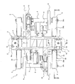
- FIG. 1 is a perspective view showing a railway vehicle carriage 1 according to a first embodiment of the present invention.
- FIG. 2 is a plan view of the leaf spring carriage 1 shown in FIG.
- FIG. 3 is a side view of the leaf spring carriage 1 shown in FIG.
- a railcar bogie 1 is arranged in a vehicle width direction (hereinafter also referred to as a lateral direction) as a bogie frame 3 for supporting a vehicle body 11 via an air spring 2 serving as a secondary suspension.
- the lateral beam 4 is not provided with a lateral beam extending from both lateral ends of the lateral beam 4 in the vehicle longitudinal direction (hereinafter also referred to as the front-rear direction).
- a pair of front and rear axles 5 is disposed along the lateral direction in front and rear of the lateral beam 4, and wheels 6 are fixed to both lateral sides of the axle 5.
- Bearings 7 that rotatably support the axle 5 are provided at both lateral ends of the axle 5 so as to be laterally outer than the wheels 6, and the bearings 7 are accommodated in an axle box 8.
- An electric motor 9 is attached to the side beam 4, and a gear box 10 in which a reduction gear for transmitting power to the axle 5 is accommodated is connected to the output shaft of the electric motor 9.
- the side cover 4 is also provided with a brake device (not shown) for braking the rotation of the wheels 6.
- the lateral beam 4 includes a pair of square pipes 12 made of metal extending in the lateral direction and connection plates 13 and 14 made of metal for connecting the square pipes 12.
- the connection plates 13 and 14 are connected to the square pipe 12. On the other hand, it is fixed by welding or bolt connection.
- a pair of cylindrical connecting plates 14 are provided at both ends 4 a in the lateral direction of the lateral beam 4 at intervals, and an air spring base 15 is installed on the upper surface thereof.
- the lateral length of the lateral beam 4 is longer than the distance between the left axle box 8 and the right axle box 8 (that is, the lateral beam 4 protrudes outward in the vehicle width direction from the axle box 8. ing).
- the lateral ends 4 a of the horizontal beam 4 are connected to the axle box 8 by a connecting mechanism 16.
- the coupling mechanism 16 includes a shaft beam 17 that extends integrally from the axle box 8 along the front-rear direction.
- the end portion of the shaft beam 17 is provided with a cylindrical portion 18 whose inner peripheral surface is cylindrical and whose both lateral sides are open.
- a mandrel 20 is inserted into the internal space of the cylindrical portion 18 via a rubber bush (not shown).
- a pair of receiving seats 21 and 22 constituting the coupling mechanism 16 are provided at both lateral ends 4 a of the lateral beam 4 so as to protrude in the front-rear direction.
- the upper ends of the pair of receiving seats 21 and 22 are connected by a connecting plate 23, and the connecting plate 23 is fixed to the square pipe 12 by a bolt 24.
- the receiving seats 21 and 22 are formed with insertion grooves 25 that open downward.
- the both ends of the mandrel 20 in the horizontal direction are fitted into the fitting groove 25 from below.
- the lid member 26 is fixed to the receiving seats 21 and 22 by bolts (not shown) so as to close the lower opening of the fitting groove 25, and the mandrel 20 is supported from below by the lid member 26. Yes.
- a leaf spring 30 (side member) extending in the front-rear direction is spanned between the side beam 4 and the axle box 8, and a center portion 30 a in the front-rear direction of the plate spring 30 is disposed at both end portions in the lateral direction of the side beam 4. 4a is supported, and both end portions 30c in the front-rear direction of the leaf spring 30 are supported by the axle box 8. That is, the leaf spring 30 has both the function of the primary suspension and the function of the conventional side beam.
- a support member 31 is attached to the upper end portion of the axle box 8, and both end portions 30 c in the front-rear direction of the leaf spring 30 are supported from below by the support member 31.
- the center part 30a in the front-rear direction of the leaf spring 30 is arranged so as to sink under the lateral beam 4, and contact members 33 (see FIG. 4) provided at both lateral ends 4a of the lateral beam 4 are placed from above. It has been.
- An extension 30b between the longitudinal center 30a and the longitudinal ends 30c of the leaf spring 30 is inclined downward toward the longitudinal center 30a in a side view, and the longitudinal direction of the leaf spring 30 is
- the central portion 30a is positioned below the longitudinal end portions 30c of the leaf spring 30. That is, the leaf spring 30 is formed in a bow shape that protrudes downward as a whole in a side view.
- a part of the extending portion 30b of the leaf spring 30 is disposed at a position overlapping the coupling mechanism 16 in a side view. However, the leaf spring 30 is disposed with a gap from the coupling mechanism 16. Specifically, a part of the extending portion 30 b of the leaf spring 30 passes through the space 27 sandwiched between the pair of receiving seats 21 and 22, passes below the connecting plate 23, and is positioned below the lateral beam 4. Has reached.
- FIG. 4 is a cross-sectional view of the main part showing the contact member 33 and the leaf spring 30 of the cross beam 4 in the cross section taken along the line IV-IV in FIG. 5 is a cross-sectional view taken along line VV in FIG.
- a fixed plate 32 made of metal (for example, general steel material) fixed to the lower surfaces of the pair of square pipes 12, and the lower surface of the fixed plate 32.
- a contact member 33 made of a rigid member (for example, an inelastic member made of metal, fiber reinforced resin, or the like), and the contact member 33 supports the lower surface of the leaf spring 30.
- the plate spring 30 is placed on the front-rear direction center portion 30a from above and is in free contact.
- the contact member 33 is in contact with the upper surface of the leaf spring 30 so as to be separated from the leaf spring 30 without being fixed in the vertical direction. That is, the abutting member 33 is not fixed to the leaf spring 30 by a fixing tool, but is contacted with the upper surface of the leaf spring 30 by the contact pressure between the downward load due to gravity from the lateral beam 4 and the reaction force of the leaf spring 30 against it. The contact is maintained.
- the side beam 4 is provided with a pair of guide side walls 39 projecting downward on both sides of the abutting member 33 in the lateral direction.
- the leaf spring 30 is disposed with a gap therebetween.
- the longitudinal end portions 30 c of the leaf spring 30 are located higher than the contact surface 33 a that is the lower surface of the contact member 33 of the side beam 4.
- a contact surface 33a of the contact member 33 with the leaf spring 30 has a substantially arc shape that protrudes downward in a side view.
- the curvature of the contact surface 33 a of the contact member 33 is set to be larger than the curvature of the portion of the leaf spring 30 that contacts the contact member 33 in a state where the cart 1 does not support the vehicle body 11. ing.
- the leaf spring 30 In the state where the carriage 1 supports the vehicle body 11, the leaf spring 30 is elastically deformed so that the lateral beam 4 sinks downward due to the downward load from the vehicle body 11, and the curvature of the portion of the leaf spring 30 that contacts the contact member 33 is curved. However, when the vehicle is idle, the curvature of the contact surface 33a of the contact member 33 is kept larger than the curvature of the portion of the leaf spring 30 that contacts the contact member 33 (solid line in FIG. 4).
- the curvature of the portion of the leaf spring 30 that contacts the contact member 33 increases. That is, as the downward load on the lateral beam 4 increases, the leaf spring 30 is elastically deformed to increase the contact area with the contact member 33, and from the contact portion of the leaf spring 30 with the contact member 33.
- the shortest distance from the contact point of the leaf spring 30 to the support member 31 is shortened from L1 to L2 (broken line in FIG. 4).
- the spring constant of the leaf spring 30 increases as the boarding rate on the vehicle body 11 increases and the downward load applied to the lateral beam 4 increases. Therefore, the spring constant is changed according to the change in the boarding rate, and a vehicle having a comfortable ride is realized both when the boarding rate is low and when the boarding rate is high.
- the leaf spring 30 has a two-layer structure including a lower layer portion 35 made of a fiber reinforced resin (for example, CFRP or GFRP) and an upper layer portion 36 made of a metal (for example, a general steel material) thinner than the lower layer portion 35.
- the leaf spring 30 is formed by integrally covering the upper surface side of the leaf spring main body portion (lower layer portion 35) made of fiber reinforced resin with metal (upper layer portion 36).
- the extending portion 30b of the leaf spring 30 is formed so that the thickness T gradually increases from the end portion side to the center portion side in the front-rear direction.
- the thickness of the lower layer portion 35 gradually increases from the end portion side to the center portion side in the front-rear direction, and the thickness of the upper layer portion 36 is constant.
- the thickness of the thinnest part of the lower layer part 35 is 3 to 10 times the thickness of the thinnest part of the upper layer part 36
- the thickness of the thickest part of the lower layer part 35 is the thickness of the thickest part of the upper layer part 36. 5 to 15 times greater than
- the contact portion between the contact surface 33a of the contact member 33 and the upper surface of the leaf spring 30 is provided with an uneven fitting structure which is a fitting portion that fits in the vertical direction with play.
- a concave portion 33b that is recessed upward is formed in the central portion of the contact surface 33a of the contact member 33, and a convex portion 36a that fits with the concave portion 33b with play is formed on the upper surface of the upper layer portion 36 of the leaf spring 30.
- FIG. 6 is a side view of the main part showing the leaf spring 30 and the support member 31 of the axle box 8 in the leaf spring carriage 1 shown in FIG.
- a support member 31 is placed on the upper end portion of the axle box 8.
- a hole 31a is formed in the center of the support member 31, and a convex portion 8a provided on the axle box 8 is fitted in the hole 31a.
- the support member 31 is formed by laminating the rubber plate 41, the metal plate 42, and the rubber plate 43 in order from the bottom. That is, the contact surface 33a of the support member 31 with respect to the lower layer portion 35 made of the fiber reinforced resin of the leaf spring 30 is made of rubber.
- the front and rear end portions 30c of the leaf spring 30 are placed on the support member 31 from above and are in free contact.
- the front and rear end portions 30 c of the leaf spring 30 are in contact with the upper surface of the support member 31 in a state where it is not fixed in the vertical direction with respect to the support member 31. That is, the front and rear end portions 30c of the leaf spring 30 are supported only by the contact pressure between the downward load from the leaf spring 30 and the reaction force of the support member 31 without being fixed to the support member 31 by the fixture. The contact with the upper surface of the member 31 is maintained.
- the contact portion between the contact surface 43a (upper surface) of the support member 31 and the lower surface of the leaf spring 30 is provided with an uneven fitting structure that is a fitting portion that fits in the vertical direction with play.
- a convex portion 35a that integrally protrudes downward from the lower layer portion 35 is formed at both longitudinal ends 30c of the leaf spring 30, and the convex portion 35a fits into the hole portion 31a of the support member 31 with play.
- the contact member 33 of the lateral beam 4 is placed on the front-rear direction center portion 30a of the leaf spring 30 from above and is not fixed to the leaf spring 30 in the vertical direction.
- the upper surface of 30 is in free contact.
- both front and rear end portions 30c of the leaf spring 30 are also in free contact with the upper surface of the support member 31 in a state where the both ends 30c are placed on the support member 31 of the axle box 8 from above and are not fixed in the vertical direction with respect to the support member 31. Yes. Therefore, the support structure between the leaf spring 30 and the side beam 4 and the support structure between the leaf spring 30 and the axle box 8 are simplified, and the assembly workability of the carriage 1 is greatly improved.
- the contact member 33 of the side beam 4 is in contact with the leaf spring 30 without being fixed in the vertical direction, and the support member 31 of the axle box 8 is also fixed in the vertical direction with respect to the leaf spring 30. Therefore, the torsional force is hardly transmitted between the side beam 4 and the leaf spring 30 and between the leaf spring 30 and the axle box 8. Therefore, it is not necessary to increase the strength of each member or to reinforce the carriage 1 as a countermeasure against twisting, and the weight reduction of the carriage can be promoted. In addition, since the torsional force is difficult to be transmitted between the side beam 4, the leaf spring 30, and the axle box 8, it is possible to suppress occurrence of wheel load loss on some of the wheels 6. .
- fiber reinforced resin is difficult to recycle unlike metal, but since fiber reinforced resin is used for leaf spring 30 that can be easily separated from other parts, the recyclability of members made of metal in other parts should be kept good. Can do.
- the leaf spring 30 is in contact with the abutting member 33 via the upper layer portion 36 that is a coating material made of metal, and the lower layer portion 35 made of fiber reinforced resin of the leaf spring 30 is the rubber of the support member 31. Since it is in contact with the plate 43, the fiber reinforced resin of the leaf spring 30 can be protected.
- the upper layer portion 36 is formed of a metal whose compressive strength is higher than the compressive strength of the fiber reinforced resin of the lower layer portion 35. Therefore, the upper layer portion 36 fixed to the lower layer portion 35 can serve to reinforce the lower layer portion 35 made of fiber reinforced resin when the leaf spring 30 is elastically deformed.
- the leaf spring 30 is disposed so that a part thereof overlaps the receiving seats 21 and 22 of the coupling mechanism 16 in a side view, the space occupied by the leaf spring 30 and the coupling mechanism 16 can be suppressed. it can.
- plate spring 30 is located below rather than the both ends 30c of the front-back direction of the leaf
- an uneven fitting structure that fits in a vertical direction with play is provided at a contact portion between the contact member 33 and the leaf spring 30 and a contact portion between the leaf spring 30 and the support member 31.
- the contact member 33 is placed on the plate spring 30 without being provided with a concave-convex fitting structure between the contact member 33 and the plate spring 30 without being fixed to the plate spring 30 in the horizontal direction. It is good also as a structure.
- FIG. 7 is a view corresponding to FIG. 4 of a leaf spring carriage according to a second embodiment of the present invention.
- the leaf spring bogie of the second embodiment is provided with elastic members 52 (for example, rubber) at both ends in the front-rear direction of the contact member 133 of the lateral beam 104.
- the abutting member 133 is a main body portion made of a rigid member (for example, an inelastic member made of metal, fiber reinforced resin, or the like) fixed to the lower surface of the fixing plate 32 fixed to the square pipe 12. 51 and an elastic member 52 disposed adjacent to both sides of the main body 51 in the front-rear direction.
- the lower surfaces of the main body 51 and the elastic member 52 form a substantially arc-shaped contact surface 133a that is smoothly continuous and convex downward in a side view.
- FIG. 8 is a view corresponding to FIG. 4 of a leaf spring carriage according to a third embodiment of the present invention.
- the leaf spring bogie of the third embodiment is provided with an elastic member 152 (for example, rubber) in surface contact with the upper surface of the leaf spring 30 on the lower surface of the contact member 233 of the lateral beam 204.
- the abutment member 233 is a main body portion made of a rigid member (for example, an inelastic member made of metal, fiber reinforced resin, or the like) fixed to the lower surface of the fixing plate 32 fixed to the square pipe 12.
- 51 and an elastic member 152 covering the lower surface of the main body 51 and both ends in the front-rear direction.
- the lower surface of the main body 51 has a substantially arc shape that protrudes downward in a side view
- the lower surface of the elastic member 152 forms a substantially arc-shaped contact surface 233a that protrudes downward in a side view. ing.
- the entire contact surface 233a (lower surface) of the elastic member 152 is in contact with the upper surface of the leaf spring 30. Then, in the state where the carriage supports the vehicle body, when the number of people who ride on the vehicle body increases and the downward load on the lateral beam 204 increases, the curvature of the longitudinal center portion 30a of the leaf spring 30 increases (the amount of deflection increases), The contact surface 233a of the elastic member 152 is pushed by the upper surface of the leaf spring 30, and the both sides of the elastic member 152 mainly contract in the front-rear direction.
- both side portions of the elastic member 152 mainly due to the reduction in compressive force.
- the entire contact surface 233 a of the contact member 233 is kept in surface contact with the upper surface of the leaf spring 30. Therefore, no gap is generated between the contact surface 233a of the contact member 233 and the leaf spring 30, and dust or the like is prevented from entering the gap.
- FIG. 9 is a view corresponding to FIG. 6 of a leaf spring carriage according to a fourth embodiment of the present invention.
- the rubber plate 61 is fixed to the lower surface of the lower layer portion 35 made of fiber reinforced resin at both front and rear direction end portions 130c of the leaf spring 130 (side member).
- the support member 131 provided at the upper end of the axle box 8 is formed by laminating a rubber plate 41 and a metal plate 42 in order from the bottom.
- the upper surface of the support member 131 is formed of metal, but the lower surfaces of the front and rear direction end portions 130c of the leaf spring 130 are formed of rubber, so that the lower layer portion 35 made of fiber reinforced resin of the leaf spring 130 is excellent. Can be protected. Since other configurations are the same as those of the first embodiment described above, description thereof is omitted.
- FIG. 10 is a drawing corresponding to FIG. 6 of a leaf spring carriage according to a fifth embodiment of the present invention.
- the leaf spring carriage of the fifth embodiment is formed in a substantially arc shape in which the upper surface of the support member 231 provided at the upper end portion of the axle box 8 is convex upward in a side view.
- the support member 231 is formed by laminating a rubber plate 41, a metal plate 42, and a rubber plate 143 in order from the bottom, and an upper surface 143a of the uppermost rubber plate 143 is formed in a substantially arc shape in a side view. Has been.
- the curvature of the upper surface 143a of the support member 231 is larger than the curvature of the lower surface of the portion (the front and rear direction end portions 30c) of the leaf spring 30 that contacts the support member 231.
- the shortest distance from the contact point of the leaf spring 30 with the contact member 33 (FIG. 4) to the contact point of the leaf spring 30 with the support member 231 increases the downward load on the lateral beam 4 (FIG. 4).
- plate spring 30 will increase as the boarding rate to the vehicle body 11 increases. Therefore, the spring constant is changed according to the change in the boarding rate, and a vehicle having a comfortable ride can be realized even when the boarding rate is low and high. Since other configurations are the same as those of the first embodiment described above, description thereof is omitted.
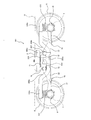
- FIG. 11 is a drawing corresponding to FIG. 3 of a carriage 301 according to the sixth embodiment of the present invention.
- the leaf spring carriage 301 according to the sixth embodiment is made of a rigid member (for example, an inelastic member made of metal, fiber reinforced resin, or the like) instead of the leaf spring 30 and extends in the front-rear direction.
- a long member 330 (side member) is used.
- the long member 330 has a cylindrical shape, for example.
- the elongate member 330 includes a front / rear direction center part 330a that supports both end parts 304a of the horizontal beam 304, a front / rear direction end part 330c that is supported by the axle box 8 and is higher than the center part 330a, 330a and the inclined part 330b which connects the both ends 330c. That is, the long member 330 forms a concave portion with the central portion 330a and a pair of inclined portions 330b at the front and rear thereof.
- a coil spring 331 is interposed as a primary suspension between both end portions 330 c of the long member 330 and the axle box 8.
- a part of the inclined portion 330b of the long member 330 is disposed at a position overlapping the coupling mechanism 16 in a side view. Specifically, a part of the inclined portion 330b of the long member 330 is inserted through the space 27 (see FIG. 1) sandwiched between the pair of receiving seats 21 and 22.
- Abutting members 333 are provided as bottom walls at both lateral ends 304a of the horizontal beam 304.
- the contact members 333 of the lateral end portions 304a of the lateral beam 304 are opened from above via a rubber plate 350 on the central portion 330a of the long member 330 in an open state without supporting the lower surface of the long member 330. It is on. That is, the contact member 333 is placed on the long member 330 so as to be separated without being fixed to the long member 330 by a fixture, and the downward load due to gravity from the lateral beam 4 and the long member 330 corresponding thereto. The state integrated with the long member 330 is maintained by the contact pressure with the reaction force.
- the contact member 333 of the horizontal beam 304 is placed on the long member 330 from above and is not fixed in the vertical direction with respect to the long member 330.
- the support structure in between is simplified, and the assembly workability of the cart is greatly improved.
- the abutting member 333 of the lateral beam 304 is not fixed in the vertical direction with respect to the long member 330, it becomes difficult to transmit a torsional force between the lateral beam 304 and the elongated member 330. Therefore, it is not necessary to increase the strength of each member or to reinforce the carriage as a countermeasure against twisting, and the weight reduction of the carriage can be promoted.
- the torsional force is difficult to be transmitted between the side beam 304 and the long member 330, it is possible to suppress occurrence of wheel load loss on some of the wheels 6.
- the abutting member 333 and the long member 330 may have a fitting portion that fits in the vertical direction, and the abutting member 333 and the long member 330 are not fixed in the vertical direction.
- the relative movement in the horizontal direction may be restricted.
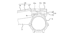
- FIG. 12 is a cross-sectional view as seen from the side (left-right direction) of the side beam 404 of the carriage according to the seventh embodiment of the present invention.
- the horizontal beam 404 of the seventh embodiment is a plate-shaped block that closes a horizontal beam main body 460 formed by cutting a metal and an opening 460 g formed on the processed surface of the horizontal beam main body 460.
- the lateral beam main body 460 is formed by cutting a hexahedron that is made of metal in the lateral direction from one surface side (the lower surface side in this example) to form a concave space S.
- the horizontal main body 460 includes five outer wall portions including an upper wall portion 460a, a front wall portion 460b, a rear wall portion 460c, a right wall portion 460d, and a left wall portion 460e, and an inner wall portion that partitions the concave space S. 460f is provided.
- a lid 461 is attached to the lower surface of the horizontal main body 460 so as to close the opening 460g of the concave space S.
- the lid 461 is a plate that is thinner than the horizontal beam main body 460 and is fixed to the horizontal beam main body 460 by a fixing tool (for example, a bolt or a screw).
- the side cover 404 can be manufactured without using welding.
- angular part of the outer surface and inner surface of the horizontal body 460 is chamfered and rounded.
- the horizontal beam 404 can be automatically manufactured by a cutting machine, and skill work such as welding is not required, so that manufacturing efficiency and manufacturing accuracy are improved.
- This configuration is combined with a configuration in which the horizontal beam 404 is not welded to the side member (the leaf spring 30 or the long member 330), so that the work for removing the accumulated distortion due to welding is greatly reduced, and the manufacturing efficiency is dramatically improved. Can be improved.
- FIG. 13 is a side view of a carriage 501 according to the eighth embodiment of the present invention.
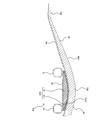
- FIG. 14 is a side view of the leaf spring 530 in the carriage 501 shown in FIG.
- the cart 501 of the eighth embodiment uses a leaf spring 530 formed in a bow shape that protrudes downward as a whole in a side view.
- the leaf spring 530 has an arc shape in which a longitudinal center portion 530a protrudes downward, and both longitudinal end portions 530c are warped upward. Therefore, the lower surfaces of the longitudinal ends 530c of the leaf spring 530 are flat surfaces but are inclined with respect to the horizontal plane. That is, the lower surfaces of both longitudinal ends 530c are inclined so as to become higher toward the outside in the vehicle longitudinal direction.
- a support member 531 is attached to the upper end portion of the axle box 8, and both longitudinal end portions 530 c of the leaf spring 530 are placed on the upper surface of the support member 531 from above. Then, the upper surface of the support member 530 is inclined with respect to the horizontal plane so as to extend along the longitudinal ends 530c of the leaf spring 530.
- a contact member 533 having an arc-shaped lower surface 533a is provided at the lower part of both end portions 4a in the vehicle width direction of the horizontal beam 4, and the contact member 533 is formed on the longitudinal center portion 530a of the leaf spring 530 from above. It is placed and is in free contact. However, the contact member 533 and the leaf spring 530 are not provided with a fitting portion that fits in the vertical direction.
- An interposition sheet 570 (for example, a rubber sheet) that contacts the contact member 533 is provided on the upper surface of the longitudinal center 530a of the leaf spring 530.
- the leaf spring 530 has an upper layer 561, an intermediate layer 562, and a lower layer 563, and the volume of the intermediate layer 562 is larger than the entire volume of the upper layer 561 and the lower layer 563.
- the upper layer 561 and the lower layer 563 are formed of CFRP, and the intermediate layer 562 is formed of GFRP.
- CFRP has higher strength against tension or compression than GFRP.
- the thickness of the leaf spring 530 is formed so as to gradually decrease from the longitudinal central portion 530a toward both longitudinal end portions 530c.
- the thickness of the intermediate layer 562 is formed so as to gradually decrease from the longitudinal center portion 530a toward the longitudinal end portions 530c, and the thicknesses of the upper layer 561 and the lower layer 563 are constant, and the thickness of the upper layer 561 is constant.
- the thickness is thinner than the wall thickness of the lower layer 563.
- the inclination angle ⁇ of the longitudinal ends 530c of the leaf spring 530 with respect to the horizontal plane is set to a value of 10 ° to 25 ° (for example, 15 °). .
- vibrations in the up / down, front / rear and left / right directions are transmitted from the wheels 6 to the bogie frame, and the vertical vibration component which is the dominant acceleration among the vibration components is transmitted and absorbed by the leaf spring 530.
- the upward force F transmitted from the support member 531 to the leaf spring 530 by vibration is applied to the longitudinal ends 530c of the leaf spring 530.
- the leaf spring 530 is not fixed to the contact member 533, and can rotate like a seesaw along the arcuate lower surface 533a of the contact member 533. Therefore, when vertical vibration is transmitted to the end 530c on one side in the longitudinal direction of the leaf spring 530, acceleration of the vertical vibration can be absorbed also by rotation about the longitudinal center portion 530a of the leaf spring 530.
- the end portion on the side having the larger inclination angle ⁇ becomes larger than the inclination angle ⁇ of the end portion 530c on the other side in the longitudinal direction due to vibration, the end portion on the side having the larger inclination angle ⁇ .
- the component force Fa of 530c is smaller than the component force Fa of the end portion 530c on the side where the inclination angle ⁇ is small. Therefore, a force is applied so that the inclination angles ⁇ on both sides in the longitudinal direction of the leaf spring 530 are the same (that is, so as to return to the original posture), and the leaf spring 530 has a self-correcting function for maintaining equilibrium. .
- the curvature of the leaf spring 530 increases.
- the direction center portion 530a falls relatively downward. This acts in the direction in which the contact member 533 supported by the longitudinal center portion 530a of the leaf spring 530 falls downward, so that an upward acceleration component transmitted from the support member 531 to the contact member 533 via the leaf spring 530.
- the longitudinal end portions 530 c of the leaf spring 530 are bent to absorb the upward acceleration transmitted from the support member 531 and to reduce the vibration transmission to the contact member 533. .
- the present invention is not limited to the above-described embodiment, and the configuration can be changed, added, or deleted without departing from the spirit of the present invention.
- the support members 31, 131, and 231 are separate objects placed on the axle box 8, but may be a part of the axle box 8.
- the contact surfaces of the contact members 33 and 133 with the plate springs 30 and 130 may be formed of rubber, and the surfaces of the plate springs 30 and 130 in contact with the rubber may be formed of fiber reinforced resin.
- the entire leaf spring may be made of fiber reinforced resin, and other than the leaf spring may be made of fiber reinforced resin.
- the coupling mechanism 16 may be omitted if the horizontal beam and the shaft box are regulated via the side member so that the horizontal relative displacement between the horizontal beam and the shaft box does not exceed a predetermined value.
- the railway vehicle bogie according to the present invention has an excellent effect of improving the assembly workability while making the bogie simple and lightweight, and is widely applied to railway vehicles capable of exhibiting the significance of this effect. This is beneficial.
Landscapes
- Engineering & Computer Science (AREA)
- Mechanical Engineering (AREA)
- Springs (AREA)
- Vibration Prevention Devices (AREA)
Abstract
Description
(第1実施形態)
図1は、本発明の第1実施形態に係る鉄道車両用台車1を表した斜視図である。図2は、図1に示す板バネ台車1の平面図である。図3は、図1に示す板バネ台車1の側面図である。図1乃至3に示すように、鉄道車両用台車1は、二次サスペンションとなる空気バネ2を介して車体11を支持するための台車枠3として車幅方向(以下、横方向ともいう)に延びる横ばり4を備えているが、横ばり4の横方向両端部から車両長手方向(以下、前後方向ともいう)に延びる側ばりを備えていない。横ばり4の前方及び後方には、横方向に沿って前後一対の車軸5が配置されており、車軸5の横方向両側には車輪6が固定されている。車軸5の横方向両端部には、車輪6よりも横方向外側にて車軸5を回転自在に支持する軸受7が設けられ、その軸受7は軸箱8に収容されている。横ばり4には、電動機9が取り付けられており、その電動機9の出力軸には、車軸5に動力を伝達する減速ギヤが収容されたギヤボックス10が接続されている。なお、横ばり4には、車輪6の回転を制動するためのブレーキ装置(図示せず)も設けられている。
図7は、本発明の第2実施形態に係る板バネ台車の図4相当の図面である。図7に示すように、第2実施形態の板バネ台車は、横ばり104の当接部材133の前後方向両端部分に弾性部材52(例えば、ゴム)を設けている。具体的には、当接部材133は、角パイプ12に固定された固定板32の下面に固定された剛性部材(例えば、金属や繊維強化樹脂等で構成された非弾性部材)からなる本体部51と、その本体部51の前後方向両側に隣接して配置された弾性部材52とを備えている。本体部51及び弾性部材52の下面は、側面視で滑らかに連続して下方に向けて凸となる略円弧形状の接触面133aを形成している。これにより、横ばり104に対する下方荷重の増加によって板バネ30が弾性変形して当接部材133の前後方向両端部分に接触しても、当該部分が弾性部材52からなるので、板バネ30への局所的な負荷を良好に緩和することができる。なお、他の構成は前述した第1実施形態と同様であるため説明を省略する。
図8は、本発明の第3実施形態に係る板バネ台車の図4相当の図面である。図8に示すように、第3実施形態の板バネ台車は、横ばり204の当接部材233の下面に板バネ30の上面と面接触する弾性部材152(例えば、ゴム)を設けている。具体的には、当接部材233は、角パイプ12に固定された固定板32の下面に固定された剛性部材(例えば、金属や繊維強化樹脂等で構成された非弾性部材)からなる本体部51と、その本体部51の下面及び前後方向両端を覆う弾性部材152とを備えている。本体部51の下面は、側面視で下方に向けて凸となる略円弧形状を呈し、弾性部材152の下面は、側面視で下方に向けて凸となる略円弧形状の接触面233aを形成している。
図9は、本発明の第4実施形態に係る板バネ台車の図6相当の図面である。図9に示すように、第3実施形態の板バネ台車は、板バネ130(側部材)の前後方向両端部130cにおいて繊維強化樹脂からなる下層部35の下面にゴム板61が固着されている。軸箱8の上端部に設けた支持部材131は、下から順に、ゴム板41及び金属板42が積層されてなる。即ち、支持部材131の上面が金属で形成されているが、板バネ130の前後方向両端部130cの下面がゴムで形成されているので、板バネ130の繊維強化樹脂からなる下層部35を良好に保護することができる。なお、他の構成は前述した第1実施形態と同様であるため説明を省略する。
図10は、本発明の第5実施形態に係る板バネ台車の図6相当の図面である。図10に示すように、第5実施形態の板バネ台車は、軸箱8の上端部に設けた支持部材231の上面が側面視で上方に向けて凸である略円弧状に形成されている。具体的には、支持部材231は、下から順に、ゴム板41、金属板42及びゴム板143が積層されてなり、その最上層のゴム板143の上面143aが側面視で略円弧形状に形成されている。即ち、側面視において、支持部材231の上面143aの曲率は、板バネ30の支持部材231と接触する部分(前後方向両端部30c)の下面の曲率よりも大きい。これにより、板バネ30の当接部材33(図4)との接触箇所から板バネ30の支持部材231との接触箇所までの最短距離は、横ばり4(図4)に対する下方荷重が増加して板バネ30が弾性変形するにつれて短くなる。そうすると、車体11への乗車率が増加するにつれて板バネ30のバネ定数が増加することとなる。よって、乗車率の変化に応じてバネ定数が変化して、乗車率が低いときも高いときも乗り心地の良い車両を実現することができる。なお、他の構成は前述した第1実施形態と同様であるため説明を省略する。
図11は、本発明の第6実施形態に係る台車301の図3相当の図面である。図11に示すように、第6実施形態の板バネ台車301は、板バネ30の代わりに、剛性部材(例えば、金属や繊維強化樹脂等で構成された非弾性部材)からなり前後方向に延びる長尺部材330(側部材)を用いている。長尺部材330は、例えば、筒形状を有している。長尺部材330は、横ばり304の横方向両端部304aを支持する前後方向中央部330aと、軸箱8に支持されて中央部330aよりも高い位置にある前後方向両端部330cと、中央部330aと両端部330cとを接続する傾斜部330bとを有している。即ち、長尺部材330は、中央部330aとその前後にある一対の傾斜部330bとで凹部を構成している。長尺部材330の両端部330cと軸箱8との間には、一次サスペンションとしてコイルバネ331が介装されている。長尺部材330の傾斜部330bの一部は、側面視で連結機構16と重なる位置に配置されている。具体的には、長尺部材330の傾斜部330bの一部は、一対の受け座21,22で挟まれた空間27(図1参照)を挿通している。
図12は、本発明の第7実施形態に係る台車の横ばり404の側方(左右方向)から見た断面図である。図12に示すように、第7実施形態の横ばり404は、金属を切削加工してなる横ばり本体460と、その横ばり本体460の加工面に形成された開口部460gを塞ぐ板状の蓋461とを備えている。横ばり本体460は、金属からなる横方向に長尺の六面体を一面側(本例では下面側)から切削加工して凹空間Sが形成されたものである。これにより、横ばり本体460は、上壁部460a、前壁部460b、後壁部460c、右壁部460dおよび左壁部460eの5面の外壁部を備えるとともに、凹空間Sを区切る内壁部460fを備える。そして、横ばり本体460の下面には、凹空間Sの開口部460gを塞ぐように蓋461が取り付けられている。この蓋461は、横ばり本体460よりも薄肉なプレートであり、固定具(例えば、ボルトやネジ等)により横ばり本体460に固定されている。つまり、横ばり404は、溶接を用いずに製作が可能である。なお、横ばり本体460の外面及び内面の角部は、面取り加工が施されて丸められている。
図13は、本発明の第8実施形態に係る台車501の側面図である。図14は、図13に示す台車501における板バネ530の側面図である。図13及び14に示すように、第8実施形態の台車501では、側面視において全体として下方に凸となる弓形状に形成された板バネ530が用いられている。板バネ530は、側面視において、その長手方向中央部530aが下方に向けて突出する円弧形状であり、その長手方向両端部530cが上方に向けて反っている。よって、板バネ530の長手方向両端部530cの下面は、平坦面ではあるが、水平面に対して傾斜している。即ち、長手方向両端部530cの下面は、車両長手方向の外側に向かうにつれて高くなるように傾斜している。
4,104,204,304,404 横ばり
5 車軸
7 軸受
8 軸箱
11 車体
16 連結機構
30,530 板バネ(側部材)
30a,530a 前後方向中央部
30c,530c 前後方向両端部
31,131,231,531 支持部材
33,133,233,333,533 当接部材
33a 接触面
33b 凹部
35 下層部
35a 凸部
36 上層部
36a 凸部
330 長尺部材(側部材)
Claims (18)
- 鉄道車両の車体を支持するための横ばりと、
前記横ばりを挟んで車両長手方向の前方及び後方において車幅方向に沿って配置された前後一対の車軸と、
前記車軸の車幅方向両側に設けられて、前記車軸を回転自在に支持する軸受と、
前記軸受を収容する軸箱と、
前記横ばりの車幅方向両端部を支持した状態で車両長手方向に延びて、その車両長手方向両端部が前記軸箱に支持された側部材と、
前記横ばりの車幅方向両端部に設けられて、前記側部材に対して上下方向に固定されない状態で前記側部材の車両長手方向中央部に上方から載せられている当接部材と、
前記軸箱に設けられて、前記側部材の車両長手方向両端部を支持する支持部材と、を備える、鉄道車両用台車。 - 前記側部材は、板バネである、請求項1に記載の鉄道車両用台車。
- 前記支持部材は、前記軸箱の上端部に設けられ、
前記板バネの車両長手方向両端部は、前記支持部材に対して上下方向に固定されない状態で前記支持部材に上方から載せられている、請求項2に記載の鉄道車両用台車。 - 前記板バネは、前記横ばりに対する下方荷重が増加すると、弾性変形して前記当接部材との接触面積が増加する、請求項2又は3のいずれか記載の鉄道車両用台車。
- 前記板バネは、繊維強化樹脂を有している、請求項2乃至4のいずれかに記載の鉄道車両用台車。
- 前記板バネの前記当接部材との接触面、及び、前記板バネの前記支持部材との接触面のうち少なくとも一方は、前記繊維強化樹脂を被覆した被覆材から形成されている、請求項5に記載の鉄道車両用台車。
- 前記当接部材の前記板バネとの接触面、及び、前記支持部材の前記板バネとの接触面のうち少なくとも一方は、ゴムから形成され、
前記板バネの前記ゴムとの接触面は、前記繊維強化樹脂から形成されている、請求項5に記載の鉄道車両用台車。 - 前記板バネは、複数の層を有し、その上層部の圧縮強度がその下層部の圧縮強度よりも高く構成されている、請求項2乃至7のいずれかに記載の鉄道車両用台車。
- 前記下層部は、前記上層部よりも厚く且つ繊維強化樹脂からなる、請求項8に記載の鉄道車両用台車。
- 前記板バネの前後方向中央部は、前記板バネの車両長手方向両端部よりも下方に位置している、請求項2乃至9のいずれかに記載の鉄道車両用台車。
- 前記板バネの前記当接部材との接触箇所から前記板バネの前記支持部材との箇所までの最短距離は、前記横ばりに対する下方荷重が増加して前記板バネが弾性変形するにつれて短くなるように構成されている、請求項2乃至10のいずれかに記載の鉄道車両用台車。
- 前記当接部材の前記板バネとの接触面は、側面視で下方に向けて凸である略円弧形状を有し、
側面視において、前記当接部材の前記接触面の曲率は、前記板バネの前記当接部材と接触する部分の曲率よりも大きい、請求項2乃至11のいずれかに記載の鉄道車両用台車。 - 前記当接部材は、側面視で下方に向けて凸となる略円弧形状の下面が形成された剛性部材からなる本体部と、前記本体部の下面を覆い前記板バネに下面で接触する弾性部材とを有し、
前記弾性部材の下面は、前記板バネが弾性変形したときに前記板バネの上面に追従して、前記板バネの上面と面接触した状態が保たれる、請求項2乃至12のいずれかに記載の鉄道車両用台車。 - 前記横ばりと前記軸箱とを連結する連結機構をさらに備え、
前記側部材は、その一部が側面視で前記連結機構と重なるように配置されている、請求項1乃至13のいずれかに記載の鉄道車両用台車。 - 前記当接部材と前記側部材とは、互いに上下方向に嵌合する嵌合部を有している、請求項1乃至14のいずれかに記載の鉄道車両用台車。
- 前記横ばりは、金属を切削加工することで形成されてなる、請求項1乃至15のいずれかに記載の鉄道車両用台車。
- 前記側部材の車両長手方向両端部の下面は、水平面に対して傾斜している、請求項1乃至16のいずれかに記載の鉄道車両用台車。
- 前記側部材は、側面視において全体として下方に凸となる弓形状に形成されている、請求項1乃至17のいずれかに記載の鉄道車両用台車。
Priority Applications (6)
| Application Number | Priority Date | Filing Date | Title |
|---|---|---|---|
| JP2013523836A JP5442167B2 (ja) | 2011-07-14 | 2012-07-12 | 鉄道車両用台車 |
| US14/232,354 US9358989B2 (en) | 2011-07-14 | 2012-07-12 | Railcar bogie |
| EP12812067.2A EP2733041B1 (en) | 2011-07-14 | 2012-07-12 | Railway vehicle truck |
| CN201280033375.7A CN103635373B (zh) | 2011-07-14 | 2012-07-12 | 铁道车辆用转向架 |
| KR1020137025200A KR101469406B1 (ko) | 2011-07-14 | 2012-07-12 | 철도 차량용 대차 |
| US15/089,023 US9573604B2 (en) | 2011-07-14 | 2016-04-01 | Railcar bogie |
Applications Claiming Priority (4)
| Application Number | Priority Date | Filing Date | Title |
|---|---|---|---|
| JP2011-155608 | 2011-07-14 | ||
| JP2011155608 | 2011-07-14 | ||
| JP2012076653 | 2012-03-29 | ||
| JP2012-076653 | 2012-03-29 |
Related Child Applications (2)
| Application Number | Title | Priority Date | Filing Date |
|---|---|---|---|
| US14/232,354 A-371-Of-International US9358989B2 (en) | 2011-07-14 | 2012-07-12 | Railcar bogie |
| US15/089,023 Continuation US9573604B2 (en) | 2011-07-14 | 2016-04-01 | Railcar bogie |
Publications (1)
| Publication Number | Publication Date |
|---|---|
| WO2013008468A1 true WO2013008468A1 (ja) | 2013-01-17 |
Family
ID=47505771
Family Applications (1)
| Application Number | Title | Priority Date | Filing Date |
|---|---|---|---|
| PCT/JP2012/004513 WO2013008468A1 (ja) | 2011-07-14 | 2012-07-12 | 鉄道車両用台車 |
Country Status (6)
| Country | Link |
|---|---|
| US (2) | US9358989B2 (ja) |
| EP (1) | EP2733041B1 (ja) |
| JP (4) | JP5442167B2 (ja) |
| KR (1) | KR101469406B1 (ja) |
| CN (1) | CN103635373B (ja) |
| WO (1) | WO2013008468A1 (ja) |
Cited By (8)
| Publication number | Priority date | Publication date | Assignee | Title |
|---|---|---|---|---|
| WO2014203450A1 (ja) * | 2013-06-19 | 2014-12-24 | 川崎重工業株式会社 | 板バネカバー及びそれを備えた鉄道車両用台車 |
| WO2015052912A1 (ja) | 2013-10-09 | 2015-04-16 | 川崎重工業株式会社 | 鉄道車両台車用の板バネの製造方法 |
| US20150344047A1 (en) * | 2013-01-10 | 2015-12-03 | Kawasaki Jukogyo Kabushiki Kaisha | Railcar bogie |
| CN107089242A (zh) * | 2013-04-24 | 2017-08-25 | 川崎重工业株式会社 | 铁道车辆用转向架 |
| WO2017199573A1 (ja) * | 2016-05-16 | 2017-11-23 | 川崎重工業株式会社 | 鉄道車両台車の組立方法、測定治具及び鉄道車両台車 |
| CN107532671A (zh) * | 2015-06-03 | 2018-01-02 | 川崎重工业株式会社 | 板簧单元和铁道车辆用转向架 |
| CN109311491A (zh) * | 2016-06-21 | 2019-02-05 | 川崎重工业株式会社 | 铁道车辆转向架的装配方法及在该方法中使用的轴距固定治具 |
| CN113844770A (zh) * | 2021-10-18 | 2021-12-28 | 青岛中车四方轨道车辆有限公司 | 转向架存储工装及转向架运输方法 |
Families Citing this family (30)
| Publication number | Priority date | Publication date | Assignee | Title |
|---|---|---|---|---|
| WO2013008468A1 (ja) * | 2011-07-14 | 2013-01-17 | 川崎重工業株式会社 | 鉄道車両用台車 |
| USD749984S1 (en) * | 2012-05-15 | 2016-02-23 | Kawasaki Jukogyo Kabushiki Kaisha | Bogie for railcar |
| JP6068984B2 (ja) * | 2013-01-10 | 2017-01-25 | 川崎重工業株式会社 | 鉄道車両用台車 |
| JP6110669B2 (ja) * | 2013-01-10 | 2017-04-05 | 川崎重工業株式会社 | 鉄道車両用台車及びそれを備えた鉄道車両 |
| US9090296B2 (en) * | 2013-08-29 | 2015-07-28 | Deere & Company | Resilient track frame pivot mechanism |
| JP6111187B2 (ja) * | 2013-12-05 | 2017-04-05 | 川崎重工業株式会社 | 鉄道車両用軸箱支持装置 |
| AT515583A1 (de) * | 2014-03-19 | 2015-10-15 | Siemens Ag Oesterreich | Drehgestellrahmen |
| USD867209S1 (en) * | 2014-11-26 | 2019-11-19 | Ge Global Sourcing Llc | Bogie side frame |
| FR3029879B1 (fr) * | 2014-12-15 | 2017-01-13 | Alstom Transp Tech | Bogie motorise pour un vehicule ferroviaire a plancher surbaisse |
| JP6383282B2 (ja) | 2014-12-17 | 2018-08-29 | 川崎重工業株式会社 | 鉄道車両用台車 |
| CN104554324B (zh) * | 2015-01-21 | 2017-01-04 | 南车株洲电力机车有限公司 | 一种整体式构架及转向架 |
| DE112015003399B4 (de) * | 2015-02-05 | 2021-02-11 | Crrc Qingdao Sifang Co., Ltd. | Fahrwerk für einen hochgeschwindigkeitsschienenzug und rahmen davon |
| JP6510938B2 (ja) * | 2015-09-10 | 2019-05-08 | 川崎重工業株式会社 | 鉄道車両用台車の電極付き板バネの製造方法 |
| JP6506677B2 (ja) * | 2015-10-29 | 2019-04-24 | 川崎重工業株式会社 | 鉄道車両用操舵台車 |
| JP6577834B2 (ja) * | 2015-10-29 | 2019-09-18 | 川崎重工業株式会社 | 鉄道車両用操舵台車 |
| JP6506676B2 (ja) * | 2015-10-29 | 2019-04-24 | 川崎重工業株式会社 | 鉄道車両用台車の軸箱支持装置 |
| JP6620007B2 (ja) * | 2015-12-18 | 2019-12-11 | 川崎重工業株式会社 | 鉄道車両用操舵台車 |
| JP6557596B2 (ja) * | 2015-12-25 | 2019-08-07 | 川崎重工業株式会社 | 鉄道車両用台車、その輪重調整方法、及び輪重調整システム |
| JP6595905B2 (ja) * | 2015-12-25 | 2019-10-23 | 川崎重工業株式会社 | 鉄道車両用台車の輪重調整具、それを備えた鉄道車両用台車、及び鉄道車両用台車の製造方法 |
| JP6637310B2 (ja) | 2015-12-25 | 2020-01-29 | 川崎重工業株式会社 | 鉄道車両用台車 |
| JP6718237B2 (ja) * | 2016-01-14 | 2020-07-08 | 川崎重工業株式会社 | ブレーキユニットを備えた鉄道車両用操舵台車 |
| USD783474S1 (en) * | 2016-04-28 | 2017-04-11 | Ausco Products, Inc. | Brake |
| DE102016123784A1 (de) * | 2016-12-08 | 2018-06-14 | CG Rail - Chinesisch-Deutsches Forschungs- und Entwicklungszentrum für Bahn- und Verkehrstechnik Dresden GmbH | Drehgestell eines Schienenfahrzeugs mit mindestens zwei in Achslagern gelagerten Radsätzen und wenigstens einem Querträger |
| JP6530806B1 (ja) * | 2017-12-26 | 2019-06-12 | 川崎重工業株式会社 | 鉄道車両用台車 |
| CN111348067B (zh) * | 2018-12-20 | 2021-07-27 | 中车唐山机车车辆有限公司 | 转向架及轨道车辆 |
| CN110588696B (zh) * | 2019-09-27 | 2024-05-07 | 中车工业研究院有限公司 | 一种非动力转向架 |
| CN112644542B (zh) * | 2019-10-10 | 2022-07-22 | 中车唐山机车车辆有限公司 | 一种转向架 |
| JP1681707S (ja) * | 2019-10-22 | 2021-03-22 | ||
| DE102020133694B3 (de) | 2020-12-16 | 2022-05-05 | CG Rail - Chinesisch-Deutsches Forschungs- und Entwicklungszentrum für Bahn- und Verkehrstechnik Dresden GmbH | Anordnung aus einem Kinematikpaket und einem Federhebel für ein Drehgestell |
| KR102621638B1 (ko) * | 2021-12-31 | 2024-01-05 | 최준현 | 석조 건조물 해체장치, 시스템 및 방법 |
Citations (10)
| Publication number | Priority date | Publication date | Assignee | Title |
|---|---|---|---|---|
| US2097418A (en) * | 1935-05-27 | 1937-10-26 | American Steel Foundries | Spring |
| JPS5058711A (ja) * | 1973-09-20 | 1975-05-21 | ||
| JPS5511365U (ja) * | 1978-07-10 | 1980-01-24 | ||
| JPS5547950A (en) | 1978-09-27 | 1980-04-05 | Sumitomo Metal Ind | Truck for railway rolling stock that side beam is omitted |
| JPS5690771A (en) * | 1979-12-22 | 1981-07-23 | Messerschmitt Boelkow Blohm | Truck for railway rolling stock |
| JPS61143257A (ja) * | 1984-12-17 | 1986-06-30 | 住友金属工業株式会社 | 鉄道車両用台車 |
| JPH04197873A (ja) * | 1990-11-29 | 1992-07-17 | Railway Technical Res Inst | 鉄道車両用台車枠 |
| EP0601677A1 (de) * | 1992-12-08 | 1994-06-15 | INSTITUT FÜR SCHIENENFAHRZEUGE GmbH | Doppelachslaufwerk |
| JP2799078B2 (ja) | 1991-01-24 | 1998-09-17 | 川崎重工業株式会社 | 軸箱支持装置 |
| JP2000502974A (ja) * | 1997-07-24 | 2000-03-14 | アーベーベー・ダイムラー―ベンツ・トランスポルタツイオーン(テクノロジー)・ゲゼルシャフト・ミト・ベシュレンクテル・ハフツング | 軌道車両の走行装置 |
Family Cites Families (29)
| Publication number | Priority date | Publication date | Assignee | Title |
|---|---|---|---|---|
| US1508954A (en) * | 1922-03-07 | 1924-09-16 | Broussouse Fernand Louis | Bogie for rolling stock |
| US3948188A (en) | 1970-06-05 | 1976-04-06 | Swiss Aluminium Ltd. | Resilient railway bogie |
| US4237791A (en) * | 1978-08-24 | 1980-12-09 | General Steel Industries, Inc. | Radial axle railway truck disc brakes |
| US4238006A (en) * | 1978-08-24 | 1980-12-09 | General Steel Industries, Inc. | Radial axle truck disc brakes |
| GB2091660A (en) * | 1981-01-22 | 1982-08-04 | Pullmann Standard Inc | Leaf spring railway bogies |
| DE3223989C2 (de) * | 1982-06-26 | 1986-09-04 | MAN Gutehoffnungshütte GmbH, 4200 Oberhausen | Laufwerk für Schienenfahrzeuge |
| US4538524A (en) * | 1983-12-08 | 1985-09-03 | The Budd Company | Equalization means for a railway truck |
| JPH0446098Y2 (ja) * | 1985-10-23 | 1992-10-29 | ||
| DE4143519C2 (de) * | 1991-02-27 | 1998-10-29 | Abb Daimler Benz Transp | Vorrichtung zur Übertragung von Traktionskräften in Drehgestellen von Schienenfahrzeugen |
| JPH04119266U (ja) * | 1991-04-01 | 1992-10-26 | 日本車輌製造株式会社 | 鉄道車両用台車 |
| JP2879632B2 (ja) * | 1992-02-10 | 1999-04-05 | 郵政大臣 | 鉄道車両用台車 |
| JPH07654A (ja) | 1993-06-15 | 1995-01-06 | Brother Ind Ltd | ミシン |
| DE19819467A1 (de) * | 1998-04-30 | 1999-11-11 | Zahnradfabrik Friedrichshafen | Drehgestell für Schienenfahrzeuge |
| FR2780016B1 (fr) * | 1998-06-18 | 2000-08-04 | Alsthom Gec | Bogie de vehicule ferroviaire et procede de fabrication d'un longeron d'un tel bogie |
| US6439130B1 (en) * | 1998-08-06 | 2002-08-27 | Herbert Scheffel | Self-steering bogies |
| FR2782687B1 (fr) * | 1998-09-02 | 2003-01-10 | Alstom Technology | Bogie a longerons composites |
| US6053112A (en) * | 1998-12-07 | 2000-04-25 | Buckeye Steel Castings Company | Shimming of railway car primary suspensions |
| CN2441705Y (zh) * | 2000-07-06 | 2001-08-08 | 东风汽车工业联营公司新疆汽车厂 | 自平衡式双联悬架 |
| FR2862935B1 (fr) * | 2003-12-02 | 2006-03-03 | Alstom | Dispositif de liaison souple entre un longeron et une boite d'essieu |
| FR2914609B1 (fr) * | 2007-04-05 | 2009-07-10 | Alstom Transport Sa | Bogie pour vehicule ferroviaire |
| WO2009063569A1 (ja) * | 2007-11-16 | 2009-05-22 | Kawasaki Jukogyo Kabushiki Kaisha | 低床式鉄道車両用台車及びそれを備えた低床式鉄道車両 |
| JP5118081B2 (ja) * | 2009-02-13 | 2013-01-16 | 川崎重工業株式会社 | 鉄道車両用軸箱支持装置 |
| JP5010630B2 (ja) * | 2009-02-20 | 2012-08-29 | 三菱重工業株式会社 | 低床式車両 |
| WO2010137308A1 (ja) * | 2009-05-26 | 2010-12-02 | 川崎重工業株式会社 | 低床式鉄道車両用台車及びそれを備えた低床式鉄道車両 |
| US8256585B2 (en) * | 2010-08-13 | 2012-09-04 | Amsted Rail Company, Inc. | Tapered brake beam wear liner |
| WO2012137257A1 (ja) * | 2011-04-07 | 2012-10-11 | 川崎重工業株式会社 | 鉄道車両用台車 |
| WO2013008468A1 (ja) * | 2011-07-14 | 2013-01-17 | 川崎重工業株式会社 | 鉄道車両用台車 |
| US8844447B2 (en) * | 2012-02-29 | 2014-09-30 | Electro-Motive Diesel, Inc. | Frame for railway truck |
| FR2991956B1 (fr) * | 2012-06-18 | 2014-07-04 | Alstom Transport Sa | Bogie de vehicule ferroviaire a suspensions perfectionnees, notamment pour un tramway a plancher bas |
-
2012
- 2012-07-12 WO PCT/JP2012/004513 patent/WO2013008468A1/ja active Application Filing
- 2012-07-12 EP EP12812067.2A patent/EP2733041B1/en active Active
- 2012-07-12 CN CN201280033375.7A patent/CN103635373B/zh active Active
- 2012-07-12 US US14/232,354 patent/US9358989B2/en active Active
- 2012-07-12 KR KR1020137025200A patent/KR101469406B1/ko active IP Right Grant
- 2012-07-12 JP JP2013523836A patent/JP5442167B2/ja active Active
-
2013
- 2013-12-17 JP JP2013260571A patent/JP5964806B2/ja active Active
-
2016
- 2016-04-01 US US15/089,023 patent/US9573604B2/en active Active
- 2016-06-30 JP JP2016129525A patent/JP6289549B2/ja active Active
-
2018
- 2018-02-06 JP JP2018018990A patent/JP6488031B2/ja active Active
Patent Citations (10)
| Publication number | Priority date | Publication date | Assignee | Title |
|---|---|---|---|---|
| US2097418A (en) * | 1935-05-27 | 1937-10-26 | American Steel Foundries | Spring |
| JPS5058711A (ja) * | 1973-09-20 | 1975-05-21 | ||
| JPS5511365U (ja) * | 1978-07-10 | 1980-01-24 | ||
| JPS5547950A (en) | 1978-09-27 | 1980-04-05 | Sumitomo Metal Ind | Truck for railway rolling stock that side beam is omitted |
| JPS5690771A (en) * | 1979-12-22 | 1981-07-23 | Messerschmitt Boelkow Blohm | Truck for railway rolling stock |
| JPS61143257A (ja) * | 1984-12-17 | 1986-06-30 | 住友金属工業株式会社 | 鉄道車両用台車 |
| JPH04197873A (ja) * | 1990-11-29 | 1992-07-17 | Railway Technical Res Inst | 鉄道車両用台車枠 |
| JP2799078B2 (ja) | 1991-01-24 | 1998-09-17 | 川崎重工業株式会社 | 軸箱支持装置 |
| EP0601677A1 (de) * | 1992-12-08 | 1994-06-15 | INSTITUT FÜR SCHIENENFAHRZEUGE GmbH | Doppelachslaufwerk |
| JP2000502974A (ja) * | 1997-07-24 | 2000-03-14 | アーベーベー・ダイムラー―ベンツ・トランスポルタツイオーン(テクノロジー)・ゲゼルシャフト・ミト・ベシュレンクテル・ハフツング | 軌道車両の走行装置 |
Cited By (21)
| Publication number | Priority date | Publication date | Assignee | Title |
|---|---|---|---|---|
| US20150344047A1 (en) * | 2013-01-10 | 2015-12-03 | Kawasaki Jukogyo Kabushiki Kaisha | Railcar bogie |
| US9802627B2 (en) * | 2013-01-10 | 2017-10-31 | Kawasaki Jukogyo Kabushiki Kaisha | Railcar bogie |
| CN107089242B (zh) * | 2013-04-24 | 2021-09-07 | 川崎重工业株式会社 | 铁道车辆用转向架 |
| CN107089242A (zh) * | 2013-04-24 | 2017-08-25 | 川崎重工业株式会社 | 铁道车辆用转向架 |
| US10053119B2 (en) | 2013-06-19 | 2018-08-21 | Kawasaki Jukogyo Kabushiki Kaisha | Plate spring cover and railcar bogie including plate spring cover |
| WO2014203450A1 (ja) * | 2013-06-19 | 2014-12-24 | 川崎重工業株式会社 | 板バネカバー及びそれを備えた鉄道車両用台車 |
| JP2015003559A (ja) * | 2013-06-19 | 2015-01-08 | 川崎重工業株式会社 | 板バネカバー及びそれを備えた鉄道車両用台車 |
| US10427696B2 (en) | 2013-10-09 | 2019-10-01 | Kawasaki Jukogyo Kabushiki Kaisha | Method of producing plate spring for railcar bogie |
| JP2015075178A (ja) * | 2013-10-09 | 2015-04-20 | 川崎重工業株式会社 | 鉄道車両台車用の板バネの製造方法 |
| WO2015052912A1 (ja) | 2013-10-09 | 2015-04-16 | 川崎重工業株式会社 | 鉄道車両台車用の板バネの製造方法 |
| US10723371B2 (en) | 2015-06-03 | 2020-07-28 | Kawasaki Jukogyo Kabushiki Kaisha | Plate spring unit and railcar bogie |
| CN107532671B (zh) * | 2015-06-03 | 2019-09-24 | 川崎重工业株式会社 | 板簧单元和铁道车辆用转向架 |
| CN107532671A (zh) * | 2015-06-03 | 2018-01-02 | 川崎重工业株式会社 | 板簧单元和铁道车辆用转向架 |
| WO2017199573A1 (ja) * | 2016-05-16 | 2017-11-23 | 川崎重工業株式会社 | 鉄道車両台車の組立方法、測定治具及び鉄道車両台車 |
| JP2017206059A (ja) * | 2016-05-16 | 2017-11-24 | 川崎重工業株式会社 | 鉄道車両台車の組立方法、測定治具及び鉄道車両台車 |
| US11104360B2 (en) | 2016-05-16 | 2021-08-31 | Kawasaki Jukogyo Kabushiki Kaisha | Method of assembling railcar bogie, measurement jig, and railcar bogie |
| CN109311491A (zh) * | 2016-06-21 | 2019-02-05 | 川崎重工业株式会社 | 铁道车辆转向架的装配方法及在该方法中使用的轴距固定治具 |
| CN109311491B (zh) * | 2016-06-21 | 2020-10-13 | 川崎重工业株式会社 | 铁道车辆转向架的装配方法及在该方法中使用的轴距固定治具 |
| US11597414B2 (en) | 2016-06-21 | 2023-03-07 | Kawasaki Railcar Manufacturing Co., Ltd. | Method of assembling railcar bogie and wheel base fixing jig for use therein |
| CN113844770A (zh) * | 2021-10-18 | 2021-12-28 | 青岛中车四方轨道车辆有限公司 | 转向架存储工装及转向架运输方法 |
| CN113844770B (zh) * | 2021-10-18 | 2023-03-14 | 青岛中车四方轨道车辆有限公司 | 转向架存储工装及转向架运输方法 |
Also Published As
| Publication number | Publication date |
|---|---|
| JPWO2013008468A1 (ja) | 2015-02-23 |
| EP2733041B1 (en) | 2019-09-11 |
| US20140137765A1 (en) | 2014-05-22 |
| JP5442167B2 (ja) | 2014-03-12 |
| EP2733041A4 (en) | 2015-06-03 |
| CN103635373B (zh) | 2016-05-18 |
| KR101469406B1 (ko) | 2014-12-04 |
| JP2016193724A (ja) | 2016-11-17 |
| US9358989B2 (en) | 2016-06-07 |
| KR20130132998A (ko) | 2013-12-05 |
| JP2014088176A (ja) | 2014-05-15 |
| JP2018100090A (ja) | 2018-06-28 |
| EP2733041A1 (en) | 2014-05-21 |
| US9573604B2 (en) | 2017-02-21 |
| JP6289549B2 (ja) | 2018-03-07 |
| JP6488031B2 (ja) | 2019-03-20 |
| CN103635373A (zh) | 2014-03-12 |
| US20160214627A1 (en) | 2016-07-28 |
| JP5964806B2 (ja) | 2016-08-03 |
Similar Documents
| Publication | Publication Date | Title |
|---|---|---|
| JP6488031B2 (ja) | 鉄道車両用台車 | |
| JP6506630B2 (ja) | 板バネユニット及び鉄道車両用台車 | |
| JP5947590B2 (ja) | 鉄道車両用台車 | |
| JP5878791B2 (ja) | 板バネユニット及びそれを用いた鉄道車両用台車 | |
| JP5779280B2 (ja) | 鉄道車両用台車 | |
| JP5878992B2 (ja) | 鉄道車両用台車 | |
| JP6560836B2 (ja) | 鉄道車両用台車 | |
| WO2014174788A1 (ja) | 鉄道車両用台車 | |
| KR20150023872A (ko) | 철도 차량의 대차 프레임 | |
| WO2021033405A1 (ja) | 軌条車両 | |
| JP5947772B2 (ja) | 鉄道車両用台車 | |
| JP6842320B2 (ja) | 鉄道車両用台車枠及びそれを備えた台車 | |
| CN109982913B (zh) | 轨道式车辆 | |
| JP7049898B2 (ja) | 鉄道車両用台車枠 | |
| CN110753652B (zh) | 铁道车辆用驱动转向架 | |
| JP2023171110A (ja) | 鉄道車両の構造部材および鉄道車両 |
Legal Events
| Date | Code | Title | Description |
|---|---|---|---|
| 121 | Ep: the epo has been informed by wipo that ep was designated in this application |
Ref document number: 12812067 Country of ref document: EP Kind code of ref document: A1 |
|
| ENP | Entry into the national phase |
Ref document number: 2013523836 Country of ref document: JP Kind code of ref document: A |
|
| ENP | Entry into the national phase |
Ref document number: 20137025200 Country of ref document: KR Kind code of ref document: A |
|
| WWE | Wipo information: entry into national phase |
Ref document number: 14232354 Country of ref document: US |
|
| NENP | Non-entry into the national phase |
Ref country code: DE |
|
| WWE | Wipo information: entry into national phase |
Ref document number: 2012812067 Country of ref document: EP |