WO2012176482A1 - タイヤ加硫機 - Google Patents
タイヤ加硫機 Download PDFInfo
- Publication number
- WO2012176482A1 WO2012176482A1 PCT/JP2012/050469 JP2012050469W WO2012176482A1 WO 2012176482 A1 WO2012176482 A1 WO 2012176482A1 JP 2012050469 W JP2012050469 W JP 2012050469W WO 2012176482 A1 WO2012176482 A1 WO 2012176482A1
- Authority
- WO
- WIPO (PCT)
- Prior art keywords
- rack
- mounting member
- mold mounting
- teeth
- fixed
- Prior art date
- Legal status (The legal status is an assumption and is not a legal conclusion. Google has not performed a legal analysis and makes no representation as to the accuracy of the status listed.)
- Ceased
Links
Images







Classifications
-
- B—PERFORMING OPERATIONS; TRANSPORTING
- B29—WORKING OF PLASTICS; WORKING OF SUBSTANCES IN A PLASTIC STATE IN GENERAL
- B29C—SHAPING OR JOINING OF PLASTICS; SHAPING OF MATERIAL IN A PLASTIC STATE, NOT OTHERWISE PROVIDED FOR; AFTER-TREATMENT OF THE SHAPED PRODUCTS, e.g. REPAIRING
- B29C33/00—Moulds or cores; Details thereof or accessories therefor
- B29C33/02—Moulds or cores; Details thereof or accessories therefor with incorporated heating or cooling means
-
- B—PERFORMING OPERATIONS; TRANSPORTING
- B29—WORKING OF PLASTICS; WORKING OF SUBSTANCES IN A PLASTIC STATE IN GENERAL
- B29C—SHAPING OR JOINING OF PLASTICS; SHAPING OF MATERIAL IN A PLASTIC STATE, NOT OTHERWISE PROVIDED FOR; AFTER-TREATMENT OF THE SHAPED PRODUCTS, e.g. REPAIRING
- B29C35/00—Heating, cooling or curing, e.g. crosslinking or vulcanising; Apparatus therefor
- B29C35/02—Heating or curing, e.g. crosslinking or vulcanizing during moulding, e.g. in a mould
-
- B—PERFORMING OPERATIONS; TRANSPORTING
- B29—WORKING OF PLASTICS; WORKING OF SUBSTANCES IN A PLASTIC STATE IN GENERAL
- B29D—PRODUCING PARTICULAR ARTICLES FROM PLASTICS OR FROM SUBSTANCES IN A PLASTIC STATE
- B29D30/00—Producing pneumatic or solid tyres or parts thereof
- B29D30/06—Pneumatic tyres or parts thereof (e.g. produced by casting, moulding, compression moulding, injection moulding, centrifugal casting)
- B29D30/0601—Vulcanising tyres; Vulcanising presses for tyres
-
- B—PERFORMING OPERATIONS; TRANSPORTING
- B29—WORKING OF PLASTICS; WORKING OF SUBSTANCES IN A PLASTIC STATE IN GENERAL
- B29D—PRODUCING PARTICULAR ARTICLES FROM PLASTICS OR FROM SUBSTANCES IN A PLASTIC STATE
- B29D30/00—Producing pneumatic or solid tyres or parts thereof
- B29D30/06—Pneumatic tyres or parts thereof (e.g. produced by casting, moulding, compression moulding, injection moulding, centrifugal casting)
- B29D30/0601—Vulcanising tyres; Vulcanising presses for tyres
- B29D30/0662—Accessories, details or auxiliary operations
Definitions
- the present invention relates to a tire vulcanizer that vulcanizes an unvulcanized tire in a mold.
- a tire vulcanizer is a device that vulcanizes an unvulcanized tire in a mold to form a vulcanized tire, and prevents the mold from opening due to the pressure reaction force during the vulcanization process. Is fixed to a guide frame or a column.
- a holding mechanism for holding a mold against a pressure reaction force in a vulcanizer is constituted by a mold height adjusting device, a clamped member, and a clamping device. Then, when the mold height adjusting device is fixed and the clamp device is fixed to the member to be clamped, the mold is held in the vulcanization process.
- the lifting screws 14a and 14b correspond to a mold height adjusting device
- the columns 18a and 18b correspond to clamped members
- the lock devices 21a and 21b correspond to clamping devices.
- a holding mechanism for holding a mold in a conventional vulcanizer has a configuration in which a mold height adjusting device, a clamped member, and a clamping device are independent from each other, and the number of parts is also increased. There were many complicated structures.
- the mold height adjustment device uses a screw member whose trapezoidal screw shape is formed on the cylindrical surface, but maintenance such as accuracy control for processing and assembly, lubrication for performance maintenance, etc. is required.
- the present invention has been made in view of such circumstances, and the upper mold mounting member or the lower mold is adjusted while adjusting the height of the upper mold mounting member or the lower mold mounting member with a simple structure. It aims at providing the tire vulcanizer which can fix the position of an attachment member.
- the tire vulcanizer of the present invention employs the following means. That is, the tire vulcanizer according to the present invention is installed in a support member that supports an upper mold mounting member and a lower mold mounting member, and an upper mold and a lower mold mounting member that are installed in the upper mold mounting member.
- a first rack having a plurality of teeth provided on the support member along the height direction of the mold having the lower mold and a first rack provided on the upper mold mounting member or the lower mold mounting member.
- a second rack having a plurality of teeth meshing with each other, and either one of the first rack and the second rack is moved relative to the other to mesh and fix the first rack and the second rack.
- the first drive unit that releases the meshing of the second rack, and the upper mold mounting member or the lower mold mounting member with the height of the upper mold mounting member or the lower mold mounting member being constant, And a second drive unit that moves the second rack in the height direction of the mold.
- the upper mold mounting member or the lower mold mounting member (hereinafter referred to as “mold mounting member”) provided with the second rack. .) Is fixed to the support member provided with the first rack.
- the fixing of the mold mounting member and the support member is released, and the mold mounting member can be moved in the height direction of the mold, for example.
- the mold mounting member since the first rack and the second rack have a plurality of teeth arranged in the height direction of the mold, the mold mounting member has a mold mounting member in a range where the first rack and the second rack are engaged with each other. Can be adjusted and fixed to the support member.
- the first rack and the second rack move in the direction in which they mesh with each other, and the teeth of both interfere with each other and completely mesh with each other. If this is not possible, the first rack and the second rack can be completely meshed by adjusting the height of the second rack. At this time, since the second rack can be moved while the height of the mold mounting member is kept constant, the height of the mold mounting member is not changed by the influence of the meshing adjustment.
- the first driving unit and the second driving unit are not driven, and the upper mold provided with the second rack via the first rack and the second rack.
- a force may be transmitted between the mounting member or the lower mold mounting member and the support member.
- the first driving unit and the second driving unit are used only for the movement of the first rack or the second rack, and when the first rack and the second rack are engaged with each other, the pressure applied to the mold is applied.
- the reaction force is held by the first rack and the second rack without using the first drive unit and the second drive unit, and the pressure reaction force is supplied via the first rack and the second rack. It is transmitted between the upper mold mounting member or the lower mold mounting member provided with two racks and the support member.
- a link mechanism that connects the first drive unit and the first rack or the second rack relatively moved by the first drive unit may be further provided.
- the link mechanism transmits the driving force of the first drive unit movable side rack 7 to the first rack or the second rack, and relatively moves the first rack or the second rack.
- the first rack or the second rack can be moved with a compact and simple configuration.
- the teeth of the first rack and the teeth of the second rack have slopes inclined with respect to the height direction of the mold, and the slopes of the teeth of the first rack and the teeth of the second rack are opposite to each other.
- the first rack and the second rack may be relatively movable along the slope.
- the first rack and the second rack are on the inclined surface formed on the teeth.
- the first rack and the second rack are completely engaged with each other by moving relative to each other and changing the height of the second rack.
- the position of the upper mold mounting member or the lower mold mounting member can be fixed while adjusting the height of the upper mold mounting member or the lower mold mounting member with a simple structure.
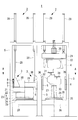
- FIG. 1 is a front view showing a vulcanizing apparatus according to a first embodiment of the present invention.
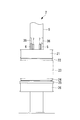
- FIG. 2 is a cross-sectional view taken along line AA in FIG.
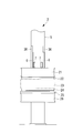
- FIG. 3 is a cross-sectional view taken along line BB in FIG. 2.
- FIG. 3 is a cross-sectional view taken along line BB in FIG. 2.
- It is a longitudinal cross-sectional view which shows the pressurization holding part of the vulcanizer which concerns on 1st Embodiment of this invention.
- It is a side view which shows the pressurization holding part of the vulcanizer which concerns on the same embodiment.
- It is a front view which shows the pressurization holding part of the vulcanizer which concerns on the same embodiment.
- the tire vulcanizer 1 includes a plurality of tire vulcanizers 2, and the tire vulcanizer 2 vulcanizes an unvulcanized tire 32 in a mold 23 to obtain a vulcanized tire 33.
- the unvulcanized tire 32 is carried into the tire vulcanizer 2 by a loader 31, and the vulcanized tire 33 is removed from the tire vulcanizer 2 by an unloader 34. It is carried out.
- the mold size of the mold 23 of the tire vulcanizer 2 is changed according to the size of the tire to be produced.
- the mold 23 includes an upper mold 4 and a lower mold 35.
- the upper mold 4 is attached to the lower side of the upper mold attachment member 21 via the upper platen 22, and moves up and down as the upper mold attachment member 21 moves up and down.
- the upper mold mounting member 21 is raised and lowered by driving a lifting hydraulic cylinder 29 provided on the upper portion of the guide frame 5.
- the upper mold mounting member 21 is provided at the lower end of a hydraulic cylinder rod 28 that enters and exits the lifting hydraulic cylinder 29.
- the upper mold 4 can be opened and closed by driving the opening / closing mold operating device 30.
- the lower mold 35 is attached and fixed to the upper surface of the pressure cylinder 25 provided on the base frame 26 via the lower platen 24.
- the base frame 26 is supported by the portal guide frame 5.
- the guide frame 5 is fixed on the installation surface of the tire vulcanizing apparatus 1, supports the upper mold attachment member 21 through the pressure holding unit 3, and supports the lower mold 35 through the base frame 26.
- the base frame 26 is an example of a lower mold attachment member.
- the bladder 27 is disposed on the upper surface of the lower mold 35 and is a thin-film elastic body.
- high-temperature and high-pressure steam is introduced into the bladder 27, and the high-temperature and high-pressure steam pressurizes and heats the unvulcanized tire 32 from the inside through the bladder 27 and presses it against the mold 23. .
- the unvulcanized tire 32 is loaded and the vulcanized tire 33 is unloaded.
- the unvulcanized tire 32 is vulcanized in the mold 23 when the upper mold 4 is positioned below.
- the pressure is applied to the inside of the mold 23 so that the pressure cylinder 25 tightens the mold 23 so that the mold 23 does not open.
- the mold 23 is fixed and held by the pressure holding unit 3. That is, the fixed side rack 6 and the movable side rack 7 receive a pressure reaction force, and the upper mold attachment member 21 tightens the mold 23. As a result, pressure is generated in the pressure cylinder 25 and the mold 23 is tightened.
- the left half of the tire vulcanizer 2 on the left side of FIG. 1 shows a case where the mold 23 has a low height and the width of the tire to be produced is narrow, and the right half has a high mold 23, The case where the width of the tire to produce is wide is shown.
- the height of the upper mold mounting member 21 when the mold 23 is fixed can be adjusted by the pressurization holding unit 3.
- the pressure holding unit 3 can fix and hold the upper mold mounting member 21 while adjusting the height of the upper mold mounting member 21 set in the vulcanization process.
- the pressure holding member 3 is fixed to the fixed rack 6 installed on the guide frame 5, the movable rack 7 installed on the upper mold mounting member 21 side, and the guide bracket 17 on the upper mold mounting member 21.
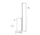
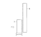
- the fixed side rack 6 is an example of a first rack, and is a rack in which a plurality of teeth are arranged in one direction. As shown in FIGS. 1 and 6, the fixed side rack 6 is provided inside the guide frame 5, and a plurality of teeth are installed along the height direction of the mold 23.
- the movable rack 7 is an example of a second rack, and is a rack in which a plurality of teeth are arranged in one direction. As shown in FIGS. 2 to 4, the movable rack 7 is provided to face the fixed rack 6. The movable rack 7 is movable with respect to the fixed rack 6, and meshes with the fixed rack 6 or is disengaged from the fixed rack 6. The movable rack 7 is driven by an air cylinder 8.
- the guide bracket 17 is provided on the upper part of the upper mold mounting member 21 as shown in FIG.
- the guide bracket 17 includes a plate member 19 erected in the vertical direction with respect to the upper mold attachment member 21, and a plate member installed on the upper surface of the upper mold attachment member 21. 20 and a plate member 18 connected to both of the plate members 19 and 20.
- the cylinder 8 is fixed to the plate member 19 of the guide bracket 17 by the fixing portion 13 (see FIG. 7).
- the movable rack 7 is connected to the piston 8 via a link 10, a plate member 9, a coupling member 11, and a rod 12. Therefore, the movable rack 7 is connected to the upper mold mounting member 21 via the guide bracket 17.
- the upper mold mounting member 21 When the fixed side rack 6 and the movable side rack 7 are engaged with each other, the upper mold mounting member 21 is fixed to the guide frame 5. On the other hand, when the meshing between the fixed rack 6 and the movable rack 7 is released, the upper mold mounting member 21 is released from the guide frame 5, and the upper mold mounting member 21 drives the lifting hydraulic cylinder 29. This makes it possible to move in the vertical direction (the height direction of the mold 23).
- the upper mold mounting member 21 is engaged with the fixed rack 6 and the movable rack 7.
- the height is adjusted to an arbitrary height as shown in FIGS. 3 and 4 show a state in which the fixed side rack 6 and the movable side rack 7 are engaged with each other.
- the movable rack 7 is engaged with the upper part of the fixed rack 6, and in FIG. 4, the movable rack 7 is engaged with the lower part of the fixed rack 6.
- the height of the mold 23 is high, and in the state of FIG. 4, the height of the mold 23 is low, and the upper mold mounting member 21 is located with respect to the guide frame 5. Fixed.
- the fixed side rack 6 and the movable side rack 7 can mesh with each other even at an intermediate position in the state shown in FIGS.
- the upper mold mounting member 21 can be fixed to the guide frame 5 in accordance with the height of various molds 23 by the pressurization holding unit 3 having the fixed side rack 6 and the movable side rack 7. It is. By adjusting the strength of the fixed side rack 6 and the movable side rack 7, it is possible to resist the pressure reaction force during the vulcanization process and firmly hold the fixed state.
- the height adjusting member 14 is connected to the upper mold attaching member 21 side of the movable rack 7.
- the height adjusting member 14 is movable in the height direction of the mold 23 together with the movable rack 7 with respect to the upper mold mounting member 21 by driving the air cylinder 15.
- the upper die mounting member 21 is provided with a slider 16 protruding toward the height adjusting member 14, and the height adjusting member 14 is provided with a through hole corresponding to the slider 16. When the slider 16 slides in the through hole, the height adjusting member 14 can move stably.
- the tips of the teeth interfere with each other depending on the positional relationship between the teeth of the fixed rack 6 and the teeth of the movable rack 7. There may be no cases.
- the height adjustment member 14 since the movable side rack 7 is movable with respect to the upper mold mounting member 21, by moving the movable side rack 7 to a position where the tooth tips do not interfere with each other, The fixed rack 6 and the movable rack 7 can be completely engaged with each other. At this time, since the movable rack 7 can be moved while the height of the upper mold mounting member 21 is kept constant, the height of the upper mold mounting member 21 is not changed by the influence of the meshing adjustment. .
- FIG. 7 shows a state before the fixed rack 6 and the movable rack 7 are engaged with each other, and the upper mold mounting member 21 is movable with respect to the guide frame 5.
- the rod 12 is accommodated in the air cylinder 8, and the coupling member 11 and the plate member 9 are positioned on the air cylinder 8 side.
- the plurality of links 10 provided on the plate member 9 are inclined with respect to the height direction of the mold 23, and the movable rack 7 is separated from the fixed rack 6.
- the movable rack 7 is oriented in the direction of the fixed rack 6 so as to mesh with the fixed rack 6. Move to. In the state shown in FIG. 7, when the tips of the teeth of the fixed side rack 6 and the movable side rack 7 interfere with each other, the height adjustment is performed by driving the air cylinder 15 while the position of the upper mold mounting member 21 is fixed. The height of the member 14 is adjusted.
- FIG. 8 shows a state after the height of the movable rack 7 is adjusted. The height adjustment member 14 is moved to the upper mold attachment member 21 side while the movable rack 7 is separated from the fixed rack 6. The state moved to.
- FIG. 9 shows a state after the fixed rack 6 and the movable rack 7 are engaged with each other, and the upper mold mounting member 21 is fixed to the guide frame 5. At this time, the rod 12 is discharged from the air cylinder 8, and the coupling member 11 and the plate member 9 are separated from the air cylinder 8. The plurality of links 10 provided on the plate member 9 are perpendicular to the height direction of the mold 23, and the movable rack 7 is engaged with the fixed rack 6.
- the pressure is applied to the inside of the mold 23 so that the pressurizing cylinder 25 tightens the mold 23 so that the mold 23 does not open.
- the clearance between the movable rack 7 and the fixed rack 6 and the clearance generated on the upper and lower surfaces of the height adjusting member 14 are all zero due to the stroke of the pressure cylinder 25.
- the reaction force from the mold 23 is transmitted in the order of the upper mold mounting member 21 ⁇ the height adjusting member 14 ⁇ the movable side rack 7 ⁇ the fixed side rack 6 ⁇ the guide frame 5. Therefore, the pressure reaction force is sufficiently transmitted to the guide frame 5 without the air cylinder 8 or the air cylinder 15 being interposed, and the pressure reaction force is maintained.
- the teeth of the fixed side rack 6 have an upper surface inclined with respect to the height direction of the mold 23 and a lower surface perpendicular to the height direction of the mold 23.
- the lower surface of the teeth of the movable rack 7 has an inclined surface that is inclined with respect to the height direction of the mold, corresponding to the upper surface of the teeth of the fixed rack 6.
- the tooth slope of the fixed rack 6 and the tooth slope of the movable rack 7 are provided to face each other.
- the fixed side rack 6 and the movable side rack 7 can be fixed even when the teeth of the both sides come into contact with each other while the fixed side rack 6 and the movable side rack 7 are moving in the meshing direction.
- the side rack 6 and the movable rack 7 move relative to each other along the slope formed on the teeth.
- the height adjustment member 14 moves upward in the height direction of the mold 23, whereby the height of the movable rack 7 is changed.
- the movable rack 7 and the fixed rack 6 are completely meshed with each other as shown in FIG.
- the teeth of the fixed side rack 6 and the teeth of the movable side rack 7 have the same dimensional shape.
- the setting of the gap dimension with respect to the pitch is considered.
- the teeth of the fixed side rack 6 and the teeth of the movable side rack 7 mesh with each other under any of the following four conditions, and thus the shape of the teeth is determined. There are four conditions: meshing without height adjustment, sliding up and down the slope without height adjustment, meshing by adjusting height, and meshing by sliding height.
- the tooth tips of the fixed rack 6 and the movable rack 7 are 1/4 or less of the tooth pitch.
- the range where the tooth tips hit each other and cannot mesh is defined to be 1 ⁇ 2 pitch or less.
- the pressure angle (flank side) of the tooth surface is an angle at which the movable rack 7 can climb the slope. This angle is defined by the friction coefficient of the pressure angle surface and the force (angle) from the link 10 acting on the movable rack 7.
- the tooth tips of the fixed side rack 6 and the movable side rack 7 are in a positional relationship such that they do not interfere with each other, as shown in FIG. In this case, only the movable side rack 7 moves to the fixed side rack 6 side, and the both are completely engaged.
- the teeth of the fixed side rack 6 and the movable side rack 7 are in contact with each other at the tip portion.
- the position of the movable rack 7 is lowered by a certain height.
- the movable rack 7 simply moves to the fixed rack 6 side. Fully mesh.
- the teeth of the fixed side rack 6 and the movable side rack 7 are in contact with each other at the tip portion.
- the position of the movable rack 7 is lowered by a certain height.
- the teeth of the fixed side rack 6 and the movable side rack 7 are in a positional relationship in which they contact with each other on the slope.
- the movable rack 7 moves along the slope, and then the two are completely engaged.
- the upper mold mounting member 21 can be mounted at any position by the combination of the driving of the height adjusting member 14 and the tooth shape of the movable rack 7 and the movable rack 7.
- the upper mold mounting member 21 can be fixed to the guide frame 5 without changing the height of the member 21.
- FIGS. 10 and 11 A second embodiment of the present invention will be described with reference to FIGS.
- two fixed side racks 6 are provided facing the guide frame 5, and two movable side racks 7 are provided corresponding to the two fixed side racks 6, respectively.
- the present invention is not limited to this example.
- one fixed side rack 6 is provided on the guide frame 5, and one movable side rack 7 corresponds to the fixed side rack 6. May be provided.
- the upper mold mounting member 21 can be fixed to the guide frame 5 while adjusting the height with a more simplified structure.
- the first and second embodiments of the present invention have a fixing function corresponding to the height of the mold 23 in a range in which the fixed side rack 6 and the movable side rack 7 can be engaged, and further a height adjusting function.
- this embodiment becomes a simplified structure compared with the case where each of the clamp apparatus and the mold height adjusting apparatus in the conventional tire vulcanizer has an independent configuration.
- a mold height adjusting device using a lifting screw is not required, and in this embodiment, the number of parts is greatly reduced.
- the design strength for resisting the pressure reaction force of the mold can be adjusted by changing the rack length and rack width of the fixed rack 6 and the movable rack 7, and a relatively simple and strong structure. can do.
- the structure is simplified, the maintainability of parts and consumable parts are improved.
- the rack provided on the guide frame 5 is fixed and the rack provided on the upper mold attachment member 21 is movable has been described.
- the present invention is not limited to this example.
- the rack provided on the upper mold attachment member 21 may be fixed, and the rack provided on the guide frame 5 may be movable with respect to the rack provided on the upper mold attachment member 21.
- the vulcanizer 2 in which the position of the lower mold 35 is always fixed and the upper mold 4 is movable with respect to the lower mold 35 has been described.
- the present invention is limited to this example.
- the position of the upper mold 4 may always be fixed, and the lower mold 35 may be movable with respect to the upper mold 4.
- the first rack and the second rack are provided corresponding to the movable lower mold mounting member.
- one of the teeth of the fixed side rack 6 and the teeth of the movable side rack 7 is inclined with respect to the height direction of the mold 23, and the other is relative to the height direction of the mold 23.
- the present invention is not limited to this example.
- the teeth of the fixed side rack 6 and the teeth of the movable side rack 7 may have other shapes as long as the upper mold mounting member 21 can be fixed at the time of meshing while adjusting the height of the upper mold mounting member 21.
Landscapes
- Engineering & Computer Science (AREA)
- Mechanical Engineering (AREA)
- Physics & Mathematics (AREA)
- Health & Medical Sciences (AREA)
- Oral & Maxillofacial Surgery (AREA)
- Thermal Sciences (AREA)
- Heating, Cooling, Or Curing Plastics Or The Like In General (AREA)
- Moulds For Moulding Plastics Or The Like (AREA)
Abstract
Description
すなわち、本発明に係るタイヤ加硫機は、上金型取付部材及び下金型取付部材を支持する支持部材と、上金型取付部材に設置された上金型及び下金型取付部材に設置された下金型を有する金型の高さ方向に沿って支持部材に設けられた複数の歯を有する第1ラックと、上金型取付部材又は下金型取付部材に設けられ、第1ラックに噛み合う複数の歯を有する第2ラックと、第1ラック及び第2ラックのいずれか一方を他方に対して相対移動させて、第1ラック及び第2ラックを噛み合わせて固定し、第1ラック及び第2ラックの噛み合いを解除する第1駆動部と、上金型取付部材又は下金型取付部材の高さを一定にしたまま、上金型取付部材又は下金型取付部材に対して、金型の高さ方向に第2ラックを移動させる第2駆動部とを備える。
以下、本発明の第1実施形態について、図1を用いて説明する。
タイヤ加硫装置1は、複数のタイヤ加硫機2からなり、タイヤ加硫機2は、未加硫タイヤ32を金型23内で加硫処理して加硫済タイヤ33とする。図1の右側のタイヤ加硫機2に示すように、未加硫タイヤ32は、ローダ31によってタイヤ加硫機2に搬入され、加硫済タイヤ33は、アンローダ34によってタイヤ加硫機2から搬出される。
加圧保持部3は、加硫処理の際に設定される上金型取付部材21の高さを調整しつつ、上金型取付部材21を固定保持することができる。加圧保持部材3は、ガイドフレーム5に設置された固定側ラック6と、上金型取付部材21側に設置された可動側ラック7と、上金型取付部材21上部のガイドブラケット17に固定されたエアシリンダ8と、高さ調整部材14と、エアシリンダ15等からなる。
図7は、固定側ラック6と可動側ラック7が噛み合う前の状態を示しており、上金型取付部材21は、ガイドフレーム5に対して移動可能である。このとき、ロッド12は、エアシリンダ8に収容されており、結合部材11と板部材9は、エアシリンダ8側に位置する。板部材9に設けられた複数のリンク10は、金型23の高さ方向に対して斜めになり、可動側ラック7は、固定側ラック6から離隔した状態である。
上記第1実施形態では、二つの固定側ラック6がガイドフレーム5に対向して設けられ、二つの固定側ラック6それぞれに対応して、二つの可動側ラック7が設けられる。一方、本発明は、この例に限定されない。図10及び図11に示す第2実施形態のタイヤ加硫機2のように、一つの固定側ラック6がガイドフレーム5に設けられ、固定側ラック6に対応して、一つの可動側ラック7が設けられてもよい。この構成によれば、より簡略化した構造で、上金型取付部材21をガイドフレーム5に対して高さ調整しつつ、固定できる。
2 タイヤ加硫機
3 加圧保持部
4 上金型
5 ガイドフレーム(支持部材)
6 固定側ラック(第1ラック)
7 可動側ラック(第2ラック)
8 エアシリンダ(第1駆動部)
9 板部材
10 リンク
11 結合部材
12 ロッド
13 固定部
14 高さ調整部材
15 エアシリンダ(第2駆動部)
16 スライダ
17 ガイドブラケット
18,19,20 板部材
21 上金型取付部材
22 上プラテン
23 開閉金型
24 下プラテン
25 加圧シリンダ
26 ベースフレーム(下金型取付部材)
27 ブラダ
28 油圧シリンダロッド
29 昇降用油圧シリンダ
30 開閉金型操作装置
31 ローダ
32 未加硫タイヤ
33 加硫済タイヤ
34 アンローダ
35 下金型
36 ラック固定部
Claims (4)
- 上金型取付部材及び下金型取付部材を支持する支持部材と、
前記上金型取付部材に設置された上金型及び前記下金型取付部材に設置された下金型を有する金型の高さ方向に沿って前記支持部材に設けられた複数の歯を有する第1ラックと、
前記上金型取付部材又は前記下金型取付部材に設けられ、前記第1ラックに噛み合う複数の歯を有する第2ラックと、
前記第1ラック及び前記第2ラックのいずれか一方を他方に対して相対移動させて、前記第1ラック及び前記第2ラックを噛み合わせて固定し、前記第1ラック及び前記第2ラックの噛み合いを解除する第1駆動部と、
前記上金型取付部材又は前記下金型取付部材の高さを一定にしたまま、前記上金型取付部材又は前記下金型取付部材に対して、前記金型の高さ方向に前記第2ラックを移動させる第2駆動部と、
を備えるタイヤ加硫機。 - 前記第1ラック及び前記第2ラックが噛み合うとき、第1駆動部及び第2駆動部を駆動させず、前記第1ラック及び前記第2ラックを介して、前記第2ラックが設けられた前記上金型取付部材又は前記下金型取付部材と前記支持部材との間に力が伝達される請求項1に記載のタイヤ加硫機。
- 前記第1駆動部と、前記第1駆動部によって相対移動する第1ラック又は前記第2ラックとを連結するリンク機構を更に備える請求項1又は2に記載のタイヤ加硫機。
- 前記第1ラックの歯と前記第2ラックの歯は、前記金型の高さ方向に対して傾斜した斜面を有し、前記第1ラックの歯の斜面と前記第2ラックの歯の斜面は対向して設けられ、前記第1ラックの歯と前記第2ラックの歯が接触するとき、前記斜面に沿って前記第1ラック及び前記第2ラックが相対移動可能である請求項1から3のいずれか1項に記載のタイヤ加硫機。
Priority Applications (3)
| Application Number | Priority Date | Filing Date | Title |
|---|---|---|---|
| CN201280004151.3A CN103347667B (zh) | 2011-06-23 | 2012-01-12 | 轮胎加硫机 |
| KR1020137014454A KR101472235B1 (ko) | 2011-06-23 | 2012-01-12 | 타이어 가황기 |
| US13/988,943 US8714954B2 (en) | 2011-06-23 | 2012-01-12 | Tire vulcanizer |
Applications Claiming Priority (2)
| Application Number | Priority Date | Filing Date | Title |
|---|---|---|---|
| JP2011139960A JP5649522B2 (ja) | 2011-06-23 | 2011-06-23 | タイヤ加硫機 |
| JP2011-139960 | 2011-06-23 |
Publications (1)
| Publication Number | Publication Date |
|---|---|
| WO2012176482A1 true WO2012176482A1 (ja) | 2012-12-27 |
Family
ID=47422334
Family Applications (1)
| Application Number | Title | Priority Date | Filing Date |
|---|---|---|---|
| PCT/JP2012/050469 Ceased WO2012176482A1 (ja) | 2011-06-23 | 2012-01-12 | タイヤ加硫機 |
Country Status (6)
| Country | Link |
|---|---|
| US (1) | US8714954B2 (ja) |
| JP (1) | JP5649522B2 (ja) |
| KR (1) | KR101472235B1 (ja) |
| CN (1) | CN103347667B (ja) |
| TW (1) | TWI480146B (ja) |
| WO (1) | WO2012176482A1 (ja) |
Cited By (1)
| Publication number | Priority date | Publication date | Assignee | Title |
|---|---|---|---|---|
| CN110023068A (zh) * | 2016-11-30 | 2019-07-16 | 倍耐力轮胎股份公司 | 用于控制轮胎生产的固化设备的方法、固化线、处理单元和相关电子单元 |
Families Citing this family (8)
| Publication number | Priority date | Publication date | Assignee | Title |
|---|---|---|---|---|
| JP5748683B2 (ja) | 2012-02-03 | 2015-07-15 | 三菱重工マシナリーテクノロジー株式会社 | タイヤ加硫機 |
| JP5988526B2 (ja) * | 2013-10-29 | 2016-09-07 | 三菱重工マシナリーテクノロジー株式会社 | タイヤ加硫機システム、および、その組立方法 |
| TWI617412B (zh) * | 2013-10-30 | 2018-03-11 | 三菱重工機械科技股份有限公司 | 輪胎硫化機系統及其組裝方法 |
| CN105437428A (zh) * | 2015-12-28 | 2016-03-30 | 常熟市浩然精工机械制造有限公司 | 轮胎加硫机拉杆轴 |
| CN105584071A (zh) * | 2015-12-28 | 2016-05-18 | 常熟市浩然精工机械制造有限公司 | 轮胎加硫机 |
| JP6817342B2 (ja) * | 2017-02-08 | 2021-01-20 | 三菱重工機械システム株式会社 | タイヤ加硫装置 |
| CN110741239A (zh) * | 2017-06-06 | 2020-01-31 | 三菱重工机械系统株式会社 | 轮胎输送装置、具备其的轮胎试验系统及轮胎输送方法 |
| TWD203063S (zh) | 2019-01-14 | 2020-03-01 | 廈門台源自動化有限公司 | 輪胎硫化生產輸送裝置 |
Citations (2)
| Publication number | Priority date | Publication date | Assignee | Title |
|---|---|---|---|---|
| JPS6014913U (ja) * | 1983-07-11 | 1985-01-31 | 三菱重工業株式会社 | タイヤ加硫機 |
| JPS62222809A (ja) * | 1986-03-26 | 1987-09-30 | Kobe Steel Ltd | タイヤプレスにおける型締付機構 |
Family Cites Families (11)
| Publication number | Priority date | Publication date | Assignee | Title |
|---|---|---|---|---|
| US4245971A (en) * | 1979-10-18 | 1981-01-20 | Donald Macmillan & Son, Inc. | Molding machine with expandable chamber and locking means |
| US4453902A (en) * | 1983-08-04 | 1984-06-12 | Mcneil-Akron, Inc. | Tire curing press |
| IT1312425B1 (it) * | 1999-06-30 | 2002-04-17 | Wintech S R L | Pressa con attrezzatura portastampo |
| JP4773620B2 (ja) | 2001-01-09 | 2011-09-14 | 三菱重工業株式会社 | タイヤ加硫機、タイヤ加硫装置およびタイヤ加硫方法 |
| CN2546173Y (zh) * | 2002-05-17 | 2003-04-23 | 大田油压机工业股份有限公司 | 橡胶加硫机 |
| JP4183125B2 (ja) * | 2003-08-01 | 2008-11-19 | 株式会社ブリヂストン | タイヤ取出装置を有する加硫装置 |
| CN200995459Y (zh) * | 2006-12-28 | 2007-12-26 | 桂林橡胶机械厂 | 双液压缸动作同步装置 |
| JP4969274B2 (ja) | 2007-03-12 | 2012-07-04 | 三菱重工業株式会社 | 左右独立作動式コラム型加硫機 |
| CN101585218B (zh) * | 2009-07-03 | 2011-09-28 | 江苏华瑞重工机械有限公司 | 平移硫化机 |
| JP5748683B2 (ja) * | 2012-02-03 | 2015-07-15 | 三菱重工マシナリーテクノロジー株式会社 | タイヤ加硫機 |
| KR200472979Y1 (ko) * | 2012-12-13 | 2014-06-05 | 한국타이어 주식회사 | 타이어 가류 분할금형의 보관대 |
-
2011
- 2011-06-23 JP JP2011139960A patent/JP5649522B2/ja not_active Expired - Fee Related
-
2012
- 2012-01-12 KR KR1020137014454A patent/KR101472235B1/ko not_active Expired - Fee Related
- 2012-01-12 WO PCT/JP2012/050469 patent/WO2012176482A1/ja not_active Ceased
- 2012-01-12 US US13/988,943 patent/US8714954B2/en not_active Expired - Fee Related
- 2012-01-12 CN CN201280004151.3A patent/CN103347667B/zh not_active Expired - Fee Related
- 2012-01-31 TW TW101103109A patent/TWI480146B/zh not_active IP Right Cessation
Patent Citations (2)
| Publication number | Priority date | Publication date | Assignee | Title |
|---|---|---|---|---|
| JPS6014913U (ja) * | 1983-07-11 | 1985-01-31 | 三菱重工業株式会社 | タイヤ加硫機 |
| JPS62222809A (ja) * | 1986-03-26 | 1987-09-30 | Kobe Steel Ltd | タイヤプレスにおける型締付機構 |
Cited By (2)
| Publication number | Priority date | Publication date | Assignee | Title |
|---|---|---|---|---|
| CN110023068A (zh) * | 2016-11-30 | 2019-07-16 | 倍耐力轮胎股份公司 | 用于控制轮胎生产的固化设备的方法、固化线、处理单元和相关电子单元 |
| US11007734B2 (en) | 2016-11-30 | 2021-05-18 | Pirelli Tyre S.P.A. | Method, curing line, processing unit and associated electronic unit for controlling curing apparatuses for tyre production |
Also Published As
| Publication number | Publication date |
|---|---|
| KR20130109176A (ko) | 2013-10-07 |
| US20130251832A1 (en) | 2013-09-26 |
| JP2013006335A (ja) | 2013-01-10 |
| TW201302414A (zh) | 2013-01-16 |
| JP5649522B2 (ja) | 2015-01-07 |
| US8714954B2 (en) | 2014-05-06 |
| TWI480146B (zh) | 2015-04-11 |
| CN103347667B (zh) | 2016-02-17 |
| CN103347667A (zh) | 2013-10-09 |
| KR101472235B1 (ko) | 2014-12-11 |
Similar Documents
| Publication | Publication Date | Title |
|---|---|---|
| JP5649522B2 (ja) | タイヤ加硫機 | |
| JP5803939B2 (ja) | 型締装置及び成形品押出方法 | |
| CN108698292B (zh) | 注射成型机 | |
| CN104015321B (zh) | 注塑成型机的合模装置 | |
| WO2014007329A1 (ja) | ノズルタッチ機構および射出成形機 | |
| CN112406052B (zh) | 一种注塑机及其工作方法 | |
| JP5748683B2 (ja) | タイヤ加硫機 | |
| WO2016181643A1 (ja) | 型開閉装置 | |
| CN110267787A (zh) | 轮胎硫化装置 | |
| JP5064186B2 (ja) | 射出成形機 | |
| JP2009045939A (ja) | 射出成形機のトグル式型締装置 | |
| JP7039362B2 (ja) | 射出成形機 | |
| JP7285755B2 (ja) | 型締装置 | |
| JP2018519184A (ja) | 加工空間の高さ位置固定機 | |
| KR101325813B1 (ko) | 사출성형기의 하프 너트 체결 기구 | |
| JP7158995B2 (ja) | 射出成形機 | |
| CA2477327A1 (en) | Mold closing device with mold height adjustment and method for actuation thereof | |
| JP5681235B2 (ja) | 射出成形機の型締装置 | |
| CN120533151B (zh) | 一种农机皮带轮生产用的全自动生产装置 | |
| CN105697945A (zh) | 可散热的医用平台装置及其调整方法 | |
| CN223276983U (zh) | 一种金属板折弯设备 | |
| JPH0224530Y2 (ja) | ||
| CN106393545B (zh) | 一种生产泡沫产品用的锁紧装置 | |
| JPH04369513A (ja) | タイヤ加硫プレス | |
| CN101119836A (zh) | 注射成型机 |
Legal Events
| Date | Code | Title | Description |
|---|---|---|---|
| WWE | Wipo information: entry into national phase |
Ref document number: 201280004151.3 Country of ref document: CN |
|
| 121 | Ep: the epo has been informed by wipo that ep was designated in this application |
Ref document number: 12802980 Country of ref document: EP Kind code of ref document: A1 |
|
| WWE | Wipo information: entry into national phase |
Ref document number: 13988943 Country of ref document: US |
|
| ENP | Entry into the national phase |
Ref document number: 20137014454 Country of ref document: KR Kind code of ref document: A |
|
| NENP | Non-entry into the national phase |
Ref country code: DE |
|
| 122 | Ep: pct application non-entry in european phase |
Ref document number: 12802980 Country of ref document: EP Kind code of ref document: A1 |