WO2012169352A1 - 作業車両の周辺監視装置 - Google Patents
作業車両の周辺監視装置 Download PDFInfo
- Publication number
- WO2012169352A1 WO2012169352A1 PCT/JP2012/063134 JP2012063134W WO2012169352A1 WO 2012169352 A1 WO2012169352 A1 WO 2012169352A1 JP 2012063134 W JP2012063134 W JP 2012063134W WO 2012169352 A1 WO2012169352 A1 WO 2012169352A1
- Authority
- WO
- WIPO (PCT)
- Prior art keywords
- obstacle
- image
- camera
- work vehicle
- detected
- Prior art date
Links
- 238000012806 monitoring device Methods 0.000 title claims abstract description 20
- 238000001514 detection method Methods 0.000 claims description 31
- 238000012544 monitoring process Methods 0.000 claims description 10
- 238000000034 method Methods 0.000 description 22
- 240000004050 Pentaglottis sempervirens Species 0.000 description 14
- 235000004522 Pentaglottis sempervirens Nutrition 0.000 description 14
- 238000003384 imaging method Methods 0.000 description 7
- 230000015572 biosynthetic process Effects 0.000 description 4
- 238000010586 diagram Methods 0.000 description 4
- 238000003786 synthesis reaction Methods 0.000 description 4
- 230000004397 blinking Effects 0.000 description 2
- 230000015654 memory Effects 0.000 description 2
- 230000005540 biological transmission Effects 0.000 description 1
- 238000006243 chemical reaction Methods 0.000 description 1
- 239000012141 concentrate Substances 0.000 description 1
- 238000005065 mining Methods 0.000 description 1
- 239000000203 mixture Substances 0.000 description 1
- 238000012986 modification Methods 0.000 description 1
- 230000004048 modification Effects 0.000 description 1
Images


Classifications
-
- H—ELECTRICITY
- H04—ELECTRIC COMMUNICATION TECHNIQUE
- H04N—PICTORIAL COMMUNICATION, e.g. TELEVISION
- H04N7/00—Television systems
- H04N7/18—Closed-circuit television [CCTV] systems, i.e. systems in which the video signal is not broadcast
- H04N7/181—Closed-circuit television [CCTV] systems, i.e. systems in which the video signal is not broadcast for receiving images from a plurality of remote sources
-
- B—PERFORMING OPERATIONS; TRANSPORTING
- B60—VEHICLES IN GENERAL
- B60K—ARRANGEMENT OR MOUNTING OF PROPULSION UNITS OR OF TRANSMISSIONS IN VEHICLES; ARRANGEMENT OR MOUNTING OF PLURAL DIVERSE PRIME-MOVERS IN VEHICLES; AUXILIARY DRIVES FOR VEHICLES; INSTRUMENTATION OR DASHBOARDS FOR VEHICLES; ARRANGEMENTS IN CONNECTION WITH COOLING, AIR INTAKE, GAS EXHAUST OR FUEL SUPPLY OF PROPULSION UNITS IN VEHICLES
- B60K35/00—Arrangement of adaptations of instruments
-
- B60K35/29—
-
- B—PERFORMING OPERATIONS; TRANSPORTING
- B60—VEHICLES IN GENERAL
- B60P—VEHICLES ADAPTED FOR LOAD TRANSPORTATION OR TO TRANSPORT, TO CARRY, OR TO COMPRISE SPECIAL LOADS OR OBJECTS
- B60P1/00—Vehicles predominantly for transporting loads and modified to facilitate loading, consolidating the load, or unloading
- B60P1/04—Vehicles predominantly for transporting loads and modified to facilitate loading, consolidating the load, or unloading with a tipping movement of load-transporting element
- B60P1/28—Tipping body constructions
- B60P1/283—Elements of tipping devices
-
- B—PERFORMING OPERATIONS; TRANSPORTING
- B60—VEHICLES IN GENERAL
- B60R—VEHICLES, VEHICLE FITTINGS, OR VEHICLE PARTS, NOT OTHERWISE PROVIDED FOR
- B60R1/00—Optical viewing arrangements; Real-time viewing arrangements for drivers or passengers using optical image capturing systems, e.g. cameras or video systems specially adapted for use in or on vehicles
- B60R1/20—Real-time viewing arrangements for drivers or passengers using optical image capturing systems, e.g. cameras or video systems specially adapted for use in or on vehicles
- B60R1/22—Real-time viewing arrangements for drivers or passengers using optical image capturing systems, e.g. cameras or video systems specially adapted for use in or on vehicles for viewing an area outside the vehicle, e.g. the exterior of the vehicle
- B60R1/23—Real-time viewing arrangements for drivers or passengers using optical image capturing systems, e.g. cameras or video systems specially adapted for use in or on vehicles for viewing an area outside the vehicle, e.g. the exterior of the vehicle with a predetermined field of view
- B60R1/27—Real-time viewing arrangements for drivers or passengers using optical image capturing systems, e.g. cameras or video systems specially adapted for use in or on vehicles for viewing an area outside the vehicle, e.g. the exterior of the vehicle with a predetermined field of view providing all-round vision, e.g. using omnidirectional cameras
-
- B—PERFORMING OPERATIONS; TRANSPORTING
- B60—VEHICLES IN GENERAL
- B60R—VEHICLES, VEHICLE FITTINGS, OR VEHICLE PARTS, NOT OTHERWISE PROVIDED FOR
- B60R1/00—Optical viewing arrangements; Real-time viewing arrangements for drivers or passengers using optical image capturing systems, e.g. cameras or video systems specially adapted for use in or on vehicles
- B60R1/20—Real-time viewing arrangements for drivers or passengers using optical image capturing systems, e.g. cameras or video systems specially adapted for use in or on vehicles
- B60R1/22—Real-time viewing arrangements for drivers or passengers using optical image capturing systems, e.g. cameras or video systems specially adapted for use in or on vehicles for viewing an area outside the vehicle, e.g. the exterior of the vehicle
- B60R1/28—Real-time viewing arrangements for drivers or passengers using optical image capturing systems, e.g. cameras or video systems specially adapted for use in or on vehicles for viewing an area outside the vehicle, e.g. the exterior of the vehicle with an adjustable field of view
-
- E—FIXED CONSTRUCTIONS
- E02—HYDRAULIC ENGINEERING; FOUNDATIONS; SOIL SHIFTING
- E02F—DREDGING; SOIL-SHIFTING
- E02F9/00—Component parts of dredgers or soil-shifting machines, not restricted to one of the kinds covered by groups E02F3/00 - E02F7/00
- E02F9/26—Indicating devices
- E02F9/261—Surveying the work-site to be treated
-
- G—PHYSICS
- G08—SIGNALLING
- G08G—TRAFFIC CONTROL SYSTEMS
- G08G1/00—Traffic control systems for road vehicles
- G08G1/16—Anti-collision systems
- G08G1/166—Anti-collision systems for active traffic, e.g. moving vehicles, pedestrians, bikes
-
- H—ELECTRICITY
- H04—ELECTRIC COMMUNICATION TECHNIQUE
- H04N—PICTORIAL COMMUNICATION, e.g. TELEVISION
- H04N23/00—Cameras or camera modules comprising electronic image sensors; Control thereof
- H04N23/60—Control of cameras or camera modules
- H04N23/63—Control of cameras or camera modules by using electronic viewfinders
-
- H—ELECTRICITY
- H04—ELECTRIC COMMUNICATION TECHNIQUE
- H04N—PICTORIAL COMMUNICATION, e.g. TELEVISION
- H04N23/00—Cameras or camera modules comprising electronic image sensors; Control thereof
- H04N23/90—Arrangement of cameras or camera modules, e.g. multiple cameras in TV studios or sports stadiums
-
- H—ELECTRICITY
- H04—ELECTRIC COMMUNICATION TECHNIQUE
- H04N—PICTORIAL COMMUNICATION, e.g. TELEVISION
- H04N7/00—Television systems
- H04N7/18—Closed-circuit television [CCTV] systems, i.e. systems in which the video signal is not broadcast
-
- B60K2360/186—
-
- B—PERFORMING OPERATIONS; TRANSPORTING
- B60—VEHICLES IN GENERAL
- B60P—VEHICLES ADAPTED FOR LOAD TRANSPORTATION OR TO TRANSPORT, TO CARRY, OR TO COMPRISE SPECIAL LOADS OR OBJECTS
- B60P1/00—Vehicles predominantly for transporting loads and modified to facilitate loading, consolidating the load, or unloading
- B60P1/04—Vehicles predominantly for transporting loads and modified to facilitate loading, consolidating the load, or unloading with a tipping movement of load-transporting element
-
- B—PERFORMING OPERATIONS; TRANSPORTING
- B60—VEHICLES IN GENERAL
- B60Q—ARRANGEMENT OF SIGNALLING OR LIGHTING DEVICES, THE MOUNTING OR SUPPORTING THEREOF OR CIRCUITS THEREFOR, FOR VEHICLES IN GENERAL
- B60Q9/00—Arrangement or adaptation of signal devices not provided for in one of main groups B60Q1/00 - B60Q7/00, e.g. haptic signalling
- B60Q9/008—Arrangement or adaptation of signal devices not provided for in one of main groups B60Q1/00 - B60Q7/00, e.g. haptic signalling for anti-collision purposes
-
- B—PERFORMING OPERATIONS; TRANSPORTING
- B60—VEHICLES IN GENERAL
- B60R—VEHICLES, VEHICLE FITTINGS, OR VEHICLE PARTS, NOT OTHERWISE PROVIDED FOR
- B60R2300/00—Details of viewing arrangements using cameras and displays, specially adapted for use in a vehicle
- B60R2300/10—Details of viewing arrangements using cameras and displays, specially adapted for use in a vehicle characterised by the type of camera system used
- B60R2300/105—Details of viewing arrangements using cameras and displays, specially adapted for use in a vehicle characterised by the type of camera system used using multiple cameras
-
- B—PERFORMING OPERATIONS; TRANSPORTING
- B60—VEHICLES IN GENERAL
- B60R—VEHICLES, VEHICLE FITTINGS, OR VEHICLE PARTS, NOT OTHERWISE PROVIDED FOR
- B60R2300/00—Details of viewing arrangements using cameras and displays, specially adapted for use in a vehicle
- B60R2300/30—Details of viewing arrangements using cameras and displays, specially adapted for use in a vehicle characterised by the type of image processing
- B60R2300/301—Details of viewing arrangements using cameras and displays, specially adapted for use in a vehicle characterised by the type of image processing combining image information with other obstacle sensor information, e.g. using RADAR/LIDAR/SONAR sensors for estimating risk of collision
-
- B—PERFORMING OPERATIONS; TRANSPORTING
- B60—VEHICLES IN GENERAL
- B60R—VEHICLES, VEHICLE FITTINGS, OR VEHICLE PARTS, NOT OTHERWISE PROVIDED FOR
- B60R2300/00—Details of viewing arrangements using cameras and displays, specially adapted for use in a vehicle
- B60R2300/30—Details of viewing arrangements using cameras and displays, specially adapted for use in a vehicle characterised by the type of image processing
- B60R2300/303—Details of viewing arrangements using cameras and displays, specially adapted for use in a vehicle characterised by the type of image processing using joined images, e.g. multiple camera images
-
- B—PERFORMING OPERATIONS; TRANSPORTING
- B60—VEHICLES IN GENERAL
- B60R—VEHICLES, VEHICLE FITTINGS, OR VEHICLE PARTS, NOT OTHERWISE PROVIDED FOR
- B60R2300/00—Details of viewing arrangements using cameras and displays, specially adapted for use in a vehicle
- B60R2300/60—Details of viewing arrangements using cameras and displays, specially adapted for use in a vehicle characterised by monitoring and displaying vehicle exterior scenes from a transformed perspective
- B60R2300/607—Details of viewing arrangements using cameras and displays, specially adapted for use in a vehicle characterised by monitoring and displaying vehicle exterior scenes from a transformed perspective from a bird's eye viewpoint
-
- B—PERFORMING OPERATIONS; TRANSPORTING
- B60—VEHICLES IN GENERAL
- B60R—VEHICLES, VEHICLE FITTINGS, OR VEHICLE PARTS, NOT OTHERWISE PROVIDED FOR
- B60R2300/00—Details of viewing arrangements using cameras and displays, specially adapted for use in a vehicle
- B60R2300/80—Details of viewing arrangements using cameras and displays, specially adapted for use in a vehicle characterised by the intended use of the viewing arrangement
- B60R2300/802—Details of viewing arrangements using cameras and displays, specially adapted for use in a vehicle characterised by the intended use of the viewing arrangement for monitoring and displaying vehicle exterior blind spot views
-
- B—PERFORMING OPERATIONS; TRANSPORTING
- B60—VEHICLES IN GENERAL
- B60R—VEHICLES, VEHICLE FITTINGS, OR VEHICLE PARTS, NOT OTHERWISE PROVIDED FOR
- B60R2300/00—Details of viewing arrangements using cameras and displays, specially adapted for use in a vehicle
- B60R2300/80—Details of viewing arrangements using cameras and displays, specially adapted for use in a vehicle characterised by the intended use of the viewing arrangement
- B60R2300/8093—Details of viewing arrangements using cameras and displays, specially adapted for use in a vehicle characterised by the intended use of the viewing arrangement for obstacle warning
Definitions
- the present invention relates to a periphery monitoring device, and more particularly to a periphery monitoring device that monitors the periphery of a work vehicle and displays a monitoring result on a display device.
- Patent Document 1 includes an obstacle detection system, an operator interface, an interface module, and a controller connected to each other.
- an obstacle detection system when an obstacle is detected, a dangerous obstacle is displayed on the display device, and an operator is warned.
- Patent Document 2 discloses a device that presents the danger level of an obstacle within the operating position range of a work machine. Here, it is detected whether there is an obstacle around the work machine. If there is an obstacle, the positional relationship between the work machine main body and the obstacle is calculated, and the obstacle is further calculated from the work operation of the work machine. The contact risk level is calculated. Then, the alarm content corresponding to the degree of danger is output to a monitor or a voice output device.
- regions corresponding to a plurality of blind spots around a vehicle are each schematically displayed as an icon on one monitor, and further, an image of one camera displaying an obstacle is displayed.
- a blind spot area (icon) including the position where the obstacle exists is flashed (see FIG. 7 of Patent Document 1 and the description of the related specification).
- Patent Document 1 does not mention the processing in such a case at all.
- Patent Document 2 when there are a plurality of obstacles, all the obstacles are displayed on the monitor (see FIG. 9 of Patent Document 2 and the description related thereto). reference).
- Patent Document 2 in the case of a working machine such as a hydraulic excavator, since the work range extends in all directions, it is necessary to display all of a plurality of obstacles on a monitor.
- Patent Document 2 when the configuration shown in Patent Document 2 is applied to a work vehicle such as a dump truck, even objects that do not need to be recognized as obstacles are displayed on the monitor. It becomes difficult to grasp things.
- An object of the present invention is to enable an operator to easily grasp an obstacle to be most careful when a plurality of obstacles are detected around a work vehicle.
- a work vehicle periphery monitoring device is a device that monitors the periphery of a work vehicle and displays a monitoring result on a display device, and includes a plurality of cameras, an overhead image display means, an obstacle detection sensor, Camera image specifying means and camera image display means.
- the plurality of cameras are attached to the work vehicle and obtain image data around the work vehicle.
- the overhead image display means displays an overhead image around the work vehicle on the display device based on image data obtained by a plurality of cameras.
- the plurality of obstacle detection sensors are attached to the work vehicle and detect obstacles around the work vehicle.
- the camera image specifying means specifies one or more camera images in which the obstacle is photographed when one or more obstacles are detected by the obstacle detection sensor. When a plurality of camera images are specified by the camera image specifying means, the camera image display means displays a camera image having a high priority side by side with the overhead image on the display device according to the priority order set according to the running state.
- camera image data around the vehicle is obtained by a plurality of cameras. Then, an overhead view image around the vehicle is created based on the plurality of camera image data and displayed on the display device.
- a camera image in which the obstacle is photographed is specified. At this time, when a plurality of camera images are specified, a camera image with a higher priority is displayed side by side with the overhead image according to the priority set according to the running state.
- the work vehicle periphery monitoring device is the work vehicle according to the first aspect, wherein the work vehicle has a driver's cab that is biased from the center in the vehicle width direction to either the left or right side. Then, when the obstacle detection sensor does not detect the obstacle, the camera image display means displays the camera image on the side opposite to the side where the cab is provided and the front side opposite to the overhead image on the display device.
- the driver's cab is often arranged to be deviated from the center to either the left or right. It is very difficult for an operator of such a work vehicle to grasp the situation on the side opposite to the side where the cab is provided.
- the front camera image on the side opposite to the side where the cab is arranged is displayed side by side with the overhead image.
- the work vehicle periphery monitoring device is the device of the first or second aspect, wherein the overhead image display means sets a plurality of regions corresponding to each of the plurality of cameras in the overhead image, The area is displayed by being divided by a frame. And when the obstruction is detected by the obstruction detection sensor, it further includes frame emphasis display means for emphasizing the frame defining the area where the obstruction is located.
- the overhead view image has a plurality of areas set corresponding to a plurality of cameras, and each area is partitioned by a frame. And the frame which divides the area
- a work vehicle periphery monitoring device is the device according to any one of the first to third aspects of the present invention, which differs depending on the traveling state and the position of the obstacle when the obstacle is detected by the obstacle detection sensor.
- Alarm means for emitting an alarm sound is further provided.
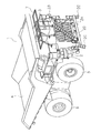
- FIG. 1 is a perspective view showing an overall configuration of a dump truck 1 including a periphery monitoring device according to an embodiment of the present invention.
- the dump truck 1 is a self-propelled super large work vehicle used for mining work or the like.
- the dump truck 1 mainly includes a vehicle body frame 2, a cab 3 as a cab, a vessel 4, two front wheels 5 and a rear wheel 6, respectively, and a base 7 for installing a pantograph for power feeding. . Moreover, this dump truck 1 is provided with the periphery monitoring apparatus 10 (refer FIG. 2) which monitors the circumference
- the vehicle body frame 2 supports a power mechanism such as a diesel engine and a transmission and other auxiliary machines (not shown). Further, front wheels 5 (only the right front wheel is shown in FIG. 1) are supported on the left and right of the front part of the vehicle body frame 2, and a rear wheel 6 (only the right rear wheel is shown in FIG. 1) are supported on the left and right of the rear part.
- the body frame 2 has a lower deck 2A on the side close to the ground, and an upper deck 2B above the lower deck 2A.
- a movable ladder 2C is provided between the lower deck 2A and the ground
- an oblique ladder 2D is provided between the lower deck 2A and the upper deck 2B.
- rail-like handrails are fixed to the left and right of the front part, the side part, and a part of the rear part.
- the cab 3 is arranged on the upper deck 2B so as to be deviated from the center in the vehicle width direction to the left side.
- a driver's seat a shift lever, a display controller, a monitor, a handle, an accelerator pedal, a brake pedal, and the like are provided.
- the controller, the monitor, and the shift lever constitute a part of the periphery monitoring device 10.
- Vessel 4 is a container for loading heavy objects such as crushed stones.
- a bottom portion on the rear side of the vessel 4 is rotatably connected to a rear end portion of the vehicle body frame 2 via a rotation pin (not shown) attached to the left and right.
- the vessel 4 has an upright posture in which the front part is rotated upward by an actuator such as a hydraulic cylinder (not shown) to discharge the load, and the front part is positioned above the cab as shown in FIG. It can take a posture.
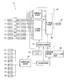
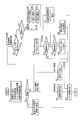
- FIG. 2 is a block diagram illustrating a configuration of the periphery monitoring device 10 provided in the dump truck 1.
- the periphery monitoring device 10 includes six cameras 11 to 16, eight radar devices 21 to 28, a vehicle body information detection unit 30, an obstacle information collection unit 32, an obstacle processing unit 33, and a cab 3 And a monitor 34 disposed in front of the driver's seat.
- the periphery monitoring apparatus 10 includes a display controller 40 that generates an image to be displayed on the monitor 34 based on the camera image data from the cameras 11 to 16 and the data from the obstacle processing unit 33.
- frame memories 11A to 16A for temporarily storing camera images are provided between the cameras 11 to 16 and the display controller 40, respectively.
- an operator switch 41 provided in the cab 3 is connected to the display controller 40.
- the operator switch 41 includes a start switch, a switch for designating a camera image to be displayed on the monitor 34 from a plurality of camera images, and the like.
- FIG. 3 is a plan view of the dump truck 1 showing the mounting positions of the six cameras 11 to 16 and the shooting range.
- photography range the actual camera imaging
- the first camera 11 is disposed at the upper end of the oblique ladder 2D, and the first shooting range 11C is the front of the vehicle.
- the second camera 12 is disposed at the right end of the front side surface of the upper deck 2B, and the second shooting range 12C is obliquely forward to the vehicle right.
- the third camera 13 is disposed symmetrically with the second camera 12, that is, at the left end portion of the front side surface of the upper deck 2B, and the third shooting range 13C is obliquely left frontward.
- the fourth camera 14 is arranged at the front end portion of the right side surface of the upper deck 2B, and the fourth imaging range 14C is diagonally right rearward.
- the fifth camera 15 is arranged symmetrically with the fourth camera, that is, at the front end of the left side surface of the upper deck 2B, and the fifth imaging range 15C is diagonally left rearward.
- the sixth camera 16 is disposed above the axle shaft connecting the two rear wheels 6 and in the vicinity of the rotation axis of the vessel 4, and the sixth imaging range 16 ⁇ / b> C is rearward.
- each of the six cameras 11 to 16 transmits camera image data, which is an image taken by itself, to the display controller 40 via the frame memories 11A to 16A.
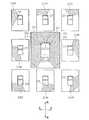
- FIG. 4 is a plan view of the dump truck 1 showing the mounting positions and detection ranges of the eight radar devices 21 to 28. As shown in FIG. As for the detection range, the actual detection range of the radar device is replaced with a range on the overhead image (see FIG. 6).
- the first radar device 21 is arranged on the lower deck 2A, and the first detection range 21R is diagonally forward left from the front of the vehicle.
- the second radar device 22 is arranged on the left side of the first radar device 21, and the second detection range 22R is diagonally forward right from the front of the vehicle.
- the third radar device 23 is disposed at the front end of the right side surface of the lower deck 2A, and the third detection range 23R is from the right front side to the right side.
- the fourth radar device 24 is disposed between the lower deck 2A and the upper deck 2B on the side of the vehicle, and the fourth detection range 24R is rearward from the right side.
- the fifth radar device 25 is disposed in the vicinity of the axle shaft that connects the two rear wheels 6, and the fifth detection range 25 ⁇ / b> R is from the right rear to the rear.
- the sixth radar device 26 is disposed on the right side of the fifth radar device 25, and the sixth detection range 25R is obliquely left rearward from the rear.
- the seventh radar device 27 is arranged at a symmetrical position with respect to the fourth radar device 24, and the seventh detection range 27R is on the left side from the rear.
- the eighth radar device 28 is disposed at a symmetrical position with respect to the third radar device 23, and the eighth detection range 28R is obliquely left forward from the left side.
- the relative position of the obstacle with respect to the dump truck 1 can be detected over almost the entire circumference of the dump truck 1 as shown in the center diagram of FIG. it can.
- the eight radar devices 21 to 28 transmit the detected obstacle data to the obstacle processing unit 33 via the obstacle information collecting unit 32.
- the vehicle body information detection unit 30 detects an operation position of a shift lever arranged around the driver seat in the cab 3 and a vehicle speed obtained by a vehicle speed sensor. Then, these data are transmitted to the display controller 40.
- the obstacle information collection unit 32 collects the reception information of each radar device 21 to 28 and outputs it to the obstacle processing unit 33.
- the obstacle processing unit 33 compares the parameter value set in advance with a threshold value and outputs obstacle information to the display controller 40.
- the relative speed, relative angle, relative distance between the dump truck 1 and the object, and the signal intensity from the object (the intensity of the radar reflected signal) are set.
- the object obstacle
- the position coordinates of the object are obtained. Further, it is determined whether or not this position coordinate is within the range where an alarm should be given as an obstacle. If the position coordinates are within the alarm range, this is output to the display controller 40 as obstacle detection information.
- the display controller 40 includes a bird's-eye view image synthesis unit 42, a camera image switching unit 43, an image display control unit 44, and a monitor image generation unit 45.
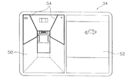
- the overhead image synthesis unit 42 receives a plurality of camera image data from each of the six cameras 11 to 16. Then, the bird's-eye view image combining unit 42 generates a bird's-eye view image 50 around the dump truck 1 as shown on the left side of FIG. 5 by combining a plurality of camera image data. Specifically, the bird's-eye view image synthesis unit 42 generates bird's-eye view image data indicating a bird's-eye view image 50 obtained by projecting a plurality of camera images on a predetermined projection plane by performing coordinate conversion on each of the plurality of camera image data. . In FIG. 5, an overhead image is displayed on the left side of one monitor 34, and one camera image (here, a real-time image taken by the first camera 11) 52 is displayed on the right side.
- FIG. 6 “front”, “right front”, “left front”, “right rear”, “left rear”, and “back” correspond to the imaging ranges 11C to 16C of the first to sixth cameras 11 to 16, respectively. ing.
- the camera image switching unit 43 selects a camera image to be displayed side by side on the overhead image. Specifically, the camera image switching unit 43 is controlled by the image display control unit 44 and selects one of the plurality of camera images according to a predetermined option. Processing for selecting one of the plurality of camera images will be described later.
- the image display control unit 44 receives information from the operator switch 41 and the vehicle body information detection unit 30 and controls the camera image switching unit 43 and the monitor image generation unit 45. In addition, the image display control unit 44 receives information from the obstacle processing unit 33 and performs control such that a frame 54 (see FIG. 5) surrounding the area where the obstacle exists in the overhead view image 50 is highlighted. Execute. The frame surrounding each area is usually displayed with a broken line. Each region is basically determined based on the shooting ranges 11C to 16C of the cameras 11 to 16, but the size and shape can be set as appropriate.
- the monitor image generation unit 45 displays the monitor image so that the overhead image data obtained by the overhead image synthesis unit 42 and one camera image selected by the camera image switching unit 43 are displayed side by side on one monitor 34. Is generated.
- the monitor image data generated by the monitor image generation unit 45 is output to the monitor 34.
- Vehicle speed Speed V1--a threshold value for determining whether an image is displayed on the monitor 34 or not.
- Priority order when obstacles are detected The priority order of cameras to be displayed on the monitor 34 when a plurality of cameras are shooting obstacles is as shown in Table 1 below. Reference numerals in parentheses indicate the shooting ranges of the cameras 11-16. “High”, “medium”, and “low” indicate the type of warning sound for the operator. “High” is a warning sound for which the on / off cycle of the sound is set to be the shortest, and to call the operator more intense attention. “Medium” is set so that the on / off cycle of the sound is longer than “High”. “Low” has the longest sound on / off period and the weakest warning.
- step S1 various kinds of data from outside are taken. Specifically, the following data is captured.
- step S2 it is determined whether or not the vehicle speed exceeds V1. If the vehicle speed exceeds V1, the process proceeds to step S3. In step S3, settings are made so that each image is not displayed on the monitor 34 and an alarm as a warning sound is not issued. This is to concentrate the operator on driving when traveling over a certain speed. Further, when the vehicle is traveling at a speed exceeding the vehicle speed V1 by this step S3, no warning sound is generated even when the oncoming vehicle is recognized as an obstacle.
- step S4 If the vehicle speed is V1 or less, the process proceeds to step S4 to step S6.
- step S4 an overhead image is generated based on each camera image data.
- step S5 a camera image to be displayed on the monitor 34 is selected. This camera image selection process is executed based on the processes after step S6.
- step S6 it is determined whether or not a specific camera has been selected by the operator.
- the process proceeds from step S6 to step S10.
- step S10 the camera designated by the operator is selected, and the process proceeds to step S11.
- step S20 the operation position of the shift lever is determined. If the operation position of the shift lever is “forward” and the speed exceeds “0”, the process proceeds to step S21, and the second camera 12 that is photographing the right front is selected. If the operation position of the shift lever is “reverse”, the process proceeds to step S22, and the sixth camera 16 photographing the rear is selected. If it is other than the above running state, the process proceeds to step S23, and the first camera 11 photographing the front is selected. For example, when the operation position of the shift lever is the “forward” position but the speed is “0”, the first camera 11 photographing the front is selected. After these processes, the process proceeds to step S11.
- step S11 it is determined whether an obstacle has been detected. If no obstacle is detected, the process proceeds from step S11 to step S5.
- step S11 it is determined whether an obstacle has been detected by a plurality of radar devices.
- step S30 it is determined whether an obstacle has been detected by a plurality of radar devices.
- step S32 from the position data of the obstacle detected by the radar device, the camera that is photographing this obstacle is specified and selected, and the process proceeds to step S5.
- step S30 If a plurality of obstacles are detected by a plurality of radar devices, the process proceeds from step S30 to step S33.
- step S33 one camera with the highest priority is selected according to Table 1 for determining priority, and the process proceeds to step S5.
- step S5 a camera image to be displayed side by side with the overhead image on the monitor 34 is selected according to the following procedure.
- Option 1 When no obstacle is detected and the operator designates a camera, the camera image of the camera designated by the operator.
- Option 2 If no obstacle is detected and the operator does not designate a camera, the camera image of the camera selected according to the operation position of the shift lever and the vehicle speed.
- Option 3 If one obstacle is detected, the camera image of the camera that is shooting the obstacle.
- Option 4 When multiple obstacles are detected in the shooting range of multiple cameras, the camera image of the camera with the highest priority according to the preset priority.
- step S4 the bird's-eye view image obtained in step S4 and the camera image of the selected camera obtained in step S5 are generated as monitor images in step S35.
- step S35 a frame surrounding an area where an obstacle exists among the six sections shown in FIG. 5 is highlighted.
- step S31 the type of warning sound is set according to the running state and the position where the obstacle is detected.
- the type of warning sound is set according to Table 1. For example, when an obstacle is detected ahead while moving forward, an on / off cycle is short and a warning sound that is harsh to the operator is set.
- a control for generating the warning sound set in step S31 is executed.
- the camera image on the monitor 34 is switched from the front camera image to the right front camera image. That is, the overhead image and the right front camera image are displayed side by side on the monitor 34.
- the speed further increases and exceeds the speed V1, the overhead image and the camera image are not displayed on the monitor 34.
- an overhead image is displayed on the left side of the monitor 34.
- an image of a camera having the highest priority according to Table 1 among the cameras shooting each of the plurality of obstacles is displayed on the right side of the monitor 34.
- a frame of a plurality of areas corresponding to the shooting ranges of the plurality of cameras shooting each of the plurality of obstacles is displayed with a red thick frame, blinking, and highlighted. .
- the on / off frequency is short according to Table 1, and an alarm sound that is annoying to the operator is emitted. Thereby, the operator can know that the degree of danger due to the obstacle is large.
- the frame of the area where the obstacle is present is highlighted in the overhead view image, and the camera image with a higher priority is displayed in accordance with the priority set according to the running state. Are displayed on the display device. Therefore, the operator can easily grasp the obstacle to be most careful.
- the camera image in front of the side opposite to the side where the cab is provided is displayed on the monitor 34 side by side with the overhead view image. Can be easily grasped through camera images.
- the priority order of the camera when a plurality of obstacles are detected or according to the running state is not limited to the above embodiment. What is necessary is just to set suitably according to arrangement
- the overhead image and the camera image are displayed side by side on one monitor, but two monitors are arranged side by side, and the overhead image and the camera image are separately displayed on each monitor. It may be.
- the periphery monitoring device of the present invention when a plurality of obstacles are detected around the work vehicle, it is possible to easily grasp the obstacle to which attention should be paid most.
Abstract
Description
図1は、本発明の一実施形態による周辺監視装置を備えたダンプトラック1の全体構成を示す斜視図である。ダンプトラック1は、鉱山作業などに用いられる自走式の超大型作業車両である。
図2は、ダンプトラック1が備える周辺監視装置10の構成を示すブロック図である。周辺監視装置10は、6台のカメラ11~16と、8台のレーダ装置21~28と、車体情報検出部30と、障害物情報収集部32と、障害物処理部33と、キャブ3内において運転席の前方に配置されるモニタ34と、を有する。また、周辺監視装置10は、カメラ11~16からのカメラ画像データと障害物処理部33からのデータによって、モニタ34に表示すべき画像を生成する表示用コントローラ40を有している。なお、各カメラ11~16と表示用コントローラ40との間には、それぞれカメラ画像を一旦記憶するフレームメモリ11A~16Aが設けられている。さらに、キャブ3内に設けられたオペレータスイッチ41が表示用コントローラ40に接続されている。オペレータスイッチ41は、起動用のスイッチ、複数のカメラ画像からモニタ34に表示すべきカメラ画像を指定するためのスイッチ等を含む。
6台のカメラ11~16は、ダンプトラック1の外周に装着され、ダンプトラック1の周囲の画像を取得する。図3は、6台のカメラ11~16の装着位置と撮影範囲とを示すダンプトラック1の平面図である。なお、撮影範囲については、実際のカメラ撮影範囲を俯瞰画像(図6参照)上の範囲に置き換えて示している。
8台のレーダ装置21~28は、ダンプトラック1の外周に装着され、ダンプトラック1の周囲に存在する障害物の相対位置を検知する。図4は、8台のレーダ装置21~28の装着位置と検知範囲とを示すダンプトラック1の平面図である。なお、検知範囲については、実際のレーダ装置の検知範囲を俯瞰画像(図6参照)上の範囲に置き換えて示している。
車体情報検出部30は、キャブ3内の運転席周辺に配置されたシフトレバーの操作位置と、車速センサによって得られる車速と、を検出する。そして、これらのデータを表示用コントローラ40に送信する。
障害物情報収集部32は、各レーダ装置21~28の受信情報を収集し、障害物処理部33に出力する。障害物処理部33は、予め設定されたパラメータの値としきい値とを比較して、障害物情報を表示用コントローラ40に対して出力する。パラメータとしては、ダンプトラック1と対象物との相対速度、相対角度、相対距離、対象物からの信号強度(レーダ反射信号の強度)が設定されている。これらのパラメータのうち、相対速度、相対角度、及び相対距離が、予め設定されているしきい値以下であり、かつ信号強度がしきい値を越えていれば、対象物(障害物)からの信号に基づいて、対象物の位置座標を求める。さらに、この位置座標が障害物として警報を行うべき範囲内の座標であるか否かを判断する。位置座標が警報範囲内である場合は、これを障害物の検知情報として表示用コントローラ40に出力する。
表示用コントローラ40は、俯瞰画像合成部42と、カメラ画像切替部43と、画像表示制御部44と、モニタ画像生成部45と、を有している。
図7のフローチャートにしたがって、モニタ34に画像を表示する制御処理について説明する。なお、画像表示制御処理を実行するに際し、以下のデータが予め設定されて記憶部(図示せず)に格納されている。
車速:速度V1--モニタ34に画像を表示するか表示しないかを判定するためのしきい値。

まず、ステップS1では、外部からの各種のデータを取り込む。具体的には、以下のデータを取り込む。
・車体情報:シフトレバーの操作位置及び車速
・オペレータSW情報:オペレータスイッチ41が操作された場合の操作情報
・障害物情報:各レーダ装置21~28からの障害物の情報
次にステップS2では、車速がV1を越えているか否かを判断する。車速がV1を越えている場合は、ステップS3に移行する。ステップS3では、モニタ34に各画像を表示せず、また警告音としての警報を発しないように設定する。これは、ある速度を越えて走行しているときは、オペレータを運転に集中させるためである。また、このステップS3によって、車速V1を越えて走行しているときには、対向車を障害物として認識したような場合でも、警告音は発せられない。
シフトレバーが「停止」から「前進」に操作された場合で、車速が「0」の場合は、俯瞰画像と前方のカメラ画像とがモニタ34に並べて表示される。
1つの障害物を検知した場合は、俯瞰画像と障害物を撮影しているカメラの画像がモニタ34に並べて表示される。このとき、俯瞰画像において、障害物を撮影しているカメラの撮影範囲に対応する領域の枠が赤い太枠で表示されるとともに点滅し、強調表示される。
(1)ダンプトラック1の周囲に障害物を検知した場合、俯瞰画像において障害物が存在する領域を囲む枠を強調表示し、障害物を撮影しているカメラ画像を俯瞰画像に並べてモニタ34に表示するので、オペレータは障害物の存在を容易に把握することができる。
本発明は以上のような実施形態に限定されるものではなく、本発明の範囲を逸脱することなく種々の変形又は修正が可能である。
2 車体フレーム
3 キャブ
10 周辺監視装置
11~16 カメラ
21~28 レーダ装置
30 車体情報検出部
32 障害物情報収集部
33 障害物処理部
34 モニタ
40 表示用コントローラ
42 俯瞰画像合成部
43 カメラ画像切替部
44 画像表示制御部
45 モニタ画像生成部
Claims (4)
- 作業車両の周囲を監視して監視結果を表示装置に表示する周辺監視装置であって、
作業車両に装着され、作業車両周囲の画像データを得るための複数のカメラと、
前記複数のカメラによって得られた画像データにより作業車両周囲の俯瞰画像を前記表示装置に表示する俯瞰画像表示手段と、
作業車両に装着され、作業車両周囲の障害物を検知する複数の障害物検知センサと、
前記障害物検知センサによって1又は複数の障害物が検知されたとき、前記障害物が撮影されている1又は複数のカメラ画像を特定するカメラ画像特定手段と、
前記カメラ画像特定手段によって複数のカメラ画像が特定されたとき、走行状態によって設定された優先順位にしたがって、優先順位の高いカメラ画像を俯瞰画像と並べて前記表示装置に表示するカメラ画像表示手段と、
を備えた作業車両の周辺監視装置。 - 前記作業車両は、車両幅方向の中央から左右いずれか一方側に偏って配置された運転室を有しており、
前記カメラ画像表示手段は、前記障害物検知センサが障害物を検知していないときは前記運転室が設けられた側と逆側前方のカメラ画像を俯瞰画像と並べて前記表示装置に表示する、
請求項1に記載の作業車両の周辺監視装置。 - 前記俯瞰画像表示手段は、俯瞰画像において前記複数のカメラのそれぞれに対応する複数の領域を設定するとともに、それぞれの前記領域を枠によって区画して表示するものであり、
前記障害物検知センサによって障害物が検知されたとき、障害物が位置する領域を区画している前記枠を強調表示する枠強調表示手段をさらに備えている、
請求項1又は2に記載の作業車両の周辺監視装置。 - 前記障害物検知センサによって障害物が検知されたとき、走行状態及び障害物の位置に応じて異なる警報音を発する警報手段をさらに備えた、請求項1から3のいずれかに記載の作業車両の周辺監視装置。
Priority Applications (6)
| Application Number | Priority Date | Filing Date | Title |
|---|---|---|---|
| US13/818,353 US9497422B2 (en) | 2011-06-07 | 2012-05-23 | Perimeter monitoring device for work vehicle |
| AU2012268476A AU2012268476B2 (en) | 2011-06-07 | 2012-05-23 | Perimeter monitoring device for work vehicle |
| CN201280002627.XA CN103080990B (zh) | 2011-06-07 | 2012-05-23 | 作业车辆的周边监视装置 |
| CA2808461A CA2808461C (en) | 2011-06-07 | 2012-05-23 | Perimeter monitoring device for work vehicle |
| JP2013519437A JP5587499B2 (ja) | 2011-06-07 | 2012-05-23 | 作業車両の周辺監視装置 |
| US15/283,557 US10321097B2 (en) | 2011-06-07 | 2016-10-03 | Perimeter monitoring device for work vehicle |
Applications Claiming Priority (4)
| Application Number | Priority Date | Filing Date | Title |
|---|---|---|---|
| JP2011-127476 | 2011-06-07 | ||
| JP2011127476 | 2011-06-07 | ||
| JP2011129461 | 2011-06-09 | ||
| JP2011-129461 | 2011-06-09 |
Related Child Applications (2)
| Application Number | Title | Priority Date | Filing Date |
|---|---|---|---|
| US13/818,353 A-371-Of-International US9497422B2 (en) | 2011-06-07 | 2012-05-23 | Perimeter monitoring device for work vehicle |
| US15/283,557 Continuation US10321097B2 (en) | 2011-06-07 | 2016-10-03 | Perimeter monitoring device for work vehicle |
Publications (1)
| Publication Number | Publication Date |
|---|---|
| WO2012169352A1 true WO2012169352A1 (ja) | 2012-12-13 |
Family
ID=47295920
Family Applications (1)
| Application Number | Title | Priority Date | Filing Date |
|---|---|---|---|
| PCT/JP2012/063134 WO2012169352A1 (ja) | 2011-06-07 | 2012-05-23 | 作業車両の周辺監視装置 |
Country Status (6)
| Country | Link |
|---|---|
| US (2) | US9497422B2 (ja) |
| JP (3) | JP5587499B2 (ja) |
| CN (1) | CN103080990B (ja) |
| AU (1) | AU2012268476B2 (ja) |
| CA (1) | CA2808461C (ja) |
| WO (1) | WO2012169352A1 (ja) |
Cited By (12)
| Publication number | Priority date | Publication date | Assignee | Title |
|---|---|---|---|---|
| JP2013080440A (ja) * | 2011-10-05 | 2013-05-02 | Toyota Motor Corp | 周辺物体表示装置および周辺物体表示方法 |
| US20140204215A1 (en) * | 2013-01-18 | 2014-07-24 | Caterpillar Inc. | Image processing system using unified images |
| JP2014183497A (ja) * | 2013-03-19 | 2014-09-29 | Sumitomo Heavy Ind Ltd | 作業機械用周辺監視装置 |
| CN106062823A (zh) * | 2014-04-24 | 2016-10-26 | 日立建机株式会社 | 作业机械的周围监视装置 |
| JP2017091093A (ja) * | 2015-11-06 | 2017-05-25 | トヨタ自動車株式会社 | 情報表示装置 |
| JP2017126847A (ja) * | 2016-01-13 | 2017-07-20 | 株式会社Jvcケンウッド | 車両用表示装置および車両用表示方法 |
| WO2017131243A1 (ja) * | 2017-02-09 | 2017-08-03 | 株式会社小松製作所 | 作業車両の周辺監視システム、作業車両、及び作業車両の周辺監視方法 |
| JP2018042205A (ja) * | 2016-09-09 | 2018-03-15 | 株式会社タダノ | 画像表示システム |
| KR101856890B1 (ko) * | 2015-07-31 | 2018-05-10 | 가부시키가이샤 고마쓰 세이사쿠쇼 | 작업 기계의 표시 시스템, 작업 기계의 표시 장치, 및 작업 기계의 표시 방법 |
| JP2020063568A (ja) * | 2018-10-15 | 2020-04-23 | 日立建機株式会社 | 作業機械 |
| KR20200070135A (ko) * | 2018-12-07 | 2020-06-17 | 아진산업(주) | 후방 개방형 트럭을 위한 어라운드 뷰 모니터 시스템 |
| CN114630081A (zh) * | 2022-03-17 | 2022-06-14 | 重庆紫光华山智安科技有限公司 | 视频播放顺序确定方法、装置、设备及介质 |
Families Citing this family (51)
| Publication number | Priority date | Publication date | Assignee | Title |
|---|---|---|---|---|
| AU2012257053A1 (en) * | 2011-05-13 | 2013-11-21 | Hitachi Construction Machinery Co., Ltd. | Device for monitoring area around working machine |
| JP5456123B1 (ja) * | 2012-09-20 | 2014-03-26 | 株式会社小松製作所 | 作業車両用周辺監視システム及び作業車両 |
| JP6243926B2 (ja) * | 2013-12-12 | 2017-12-06 | 日立建機株式会社 | 車両走行システム、搬送車の停車姿勢設定装置が実行する方法、及び搬送車の停車姿勢設定装置 |
| JP6134668B2 (ja) * | 2014-02-18 | 2017-05-24 | 日立建機株式会社 | 作業車両の障害物検知装置 |
| JP6228538B2 (ja) * | 2014-04-25 | 2017-11-08 | 株式会社小松製作所 | 周辺監視システム、作業車両、及び周辺監視方法 |
| DE102014108684B4 (de) | 2014-06-20 | 2024-02-22 | Knorr-Bremse Systeme für Nutzfahrzeuge GmbH | Fahrzeug mit Umfeldüberwachungseinrichtung sowie Verfahren zum Betreiben einer solchen Überwachungseinrichtung |
| JP6571974B2 (ja) * | 2015-04-27 | 2019-09-04 | 株式会社デンソーテン | 検出装置、検出システム、検出方法、及び、プログラム |
| WO2015125979A1 (ja) * | 2015-04-28 | 2015-08-27 | 株式会社小松製作所 | 作業機械の周辺監視装置及び作業機械の周辺監視方法 |
| JP6224029B2 (ja) * | 2015-05-21 | 2017-11-01 | 富士通テン株式会社 | 画像処理装置および画像処理方法 |
| US10486599B2 (en) | 2015-07-17 | 2019-11-26 | Magna Mirrors Of America, Inc. | Rearview vision system for vehicle |
| WO2017022042A1 (ja) * | 2015-07-31 | 2017-02-09 | 株式会社小松製作所 | 作業機械の表示システム、および作業機械の表示方法 |
| US20170132476A1 (en) * | 2015-11-08 | 2017-05-11 | Otobrite Electronics Inc. | Vehicle Imaging System |
| EP3385457A4 (en) * | 2015-11-30 | 2019-03-13 | Sumitomo Heavy Industries, Ltd. | PERIPHERAL MONITORING SYSTEM FOR A WORK MACHINE |
| US10344450B2 (en) * | 2015-12-01 | 2019-07-09 | The Charles Machine Works, Inc. | Object detection system and method |
| CN105701453B (zh) * | 2016-01-04 | 2019-07-12 | 中南大学 | 一种带障碍识别系统的铁路配碴车及其障碍识别方法 |
| USD809560S1 (en) | 2016-03-13 | 2018-02-06 | Lutron Electronics Co., Inc. | Display screen or portion thereof with set of graphical user interfaces |
| US10656265B2 (en) * | 2016-03-14 | 2020-05-19 | Hitachi Construction Machinery Co., Ltd. | Mining work machine |
| CN108432242A (zh) * | 2016-05-10 | 2018-08-21 | Jvc 建伍株式会社 | 车辆用显示装置、车辆用显示方法以及程序 |
| JP6727971B2 (ja) * | 2016-07-19 | 2020-07-22 | 株式会社クボタ | 作業車 |
| DE102016116859A1 (de) * | 2016-09-08 | 2018-03-08 | Knorr-Bremse Systeme für Nutzfahrzeuge GmbH | Sensoranordnung für ein autonom betriebenes Nutzfahrzeug und ein Verfahren zur Rundumbilderfassung |
| CN107077145A (zh) | 2016-09-09 | 2017-08-18 | 深圳市大疆创新科技有限公司 | 显示无人飞行器的障碍检测的方法和系统 |
| JP6599835B2 (ja) * | 2016-09-23 | 2019-10-30 | 日立建機株式会社 | 鉱山用作業機械、障害物判別装置、及び障害物判別方法 |
| US10511762B2 (en) * | 2016-10-24 | 2019-12-17 | Rosemount Aerospace Inc. | System and method for aircraft camera image alignment |
| JP6662762B2 (ja) * | 2016-12-19 | 2020-03-11 | 株式会社クボタ | 作業車 |
| US20180236939A1 (en) * | 2017-02-22 | 2018-08-23 | Kevin Anthony Smith | Method, System, and Device for a Forward Vehicular Vision System |
| KR102285424B1 (ko) * | 2017-04-05 | 2021-08-04 | 엘지이노텍 주식회사 | 차량의 사각영역 표시장치 및 그 표시방법 |
| JP6819431B2 (ja) | 2017-04-12 | 2021-01-27 | トヨタ自動車株式会社 | 注意喚起装置 |
| EP3389026A1 (en) * | 2017-04-12 | 2018-10-17 | Volvo Car Corporation | Apparatus and method for road vehicle driver assistance |
| JP6859216B2 (ja) * | 2017-07-03 | 2021-04-14 | トヨタ自動車株式会社 | 車両周辺表示装置 |
| JPWO2019026802A1 (ja) * | 2017-07-31 | 2020-07-27 | 住友重機械工業株式会社 | ショベル |
| EP3572590B1 (en) * | 2018-03-14 | 2022-02-09 | Hitachi Construction Machinery Co., Ltd. | Work machine |
| CN108859942A (zh) * | 2018-05-21 | 2018-11-23 | 苏州工业园区职业技术学院 | 一种自卸车的举升控制系统 |
| CN112272946B (zh) * | 2018-06-14 | 2023-06-09 | 日立安斯泰莫株式会社 | 车辆控制装置 |
| EP3598259B1 (en) * | 2018-07-19 | 2021-09-01 | Panasonic Intellectual Property Management Co., Ltd. | Information processing method and information processing system |
| CN109035866A (zh) * | 2018-08-30 | 2018-12-18 | 长安大学 | 一种道路施工车辆智能化管理系统及方法 |
| CN110874925A (zh) | 2018-08-31 | 2020-03-10 | 百度在线网络技术(北京)有限公司 | 智能路侧单元及其控制方法 |
| CN109671245B (zh) * | 2018-12-29 | 2021-03-16 | 南京奥杰智能科技有限公司 | 道路作业人员安全预警系统 |
| JP7016900B2 (ja) * | 2019-04-11 | 2022-02-07 | 三菱ロジスネクスト株式会社 | 制御装置、制御方法及びプログラム |
| EP3722522B1 (en) * | 2019-04-11 | 2024-03-27 | Mitsubishi Logisnext Co., Ltd. | Control device, control method, and program |
| US11195348B2 (en) | 2019-04-29 | 2021-12-07 | Caterpillar Inc. | System and method for determining a priority of monitoring a machine |
| JP7183121B2 (ja) * | 2019-06-25 | 2022-12-05 | 株式会社クボタ | 作業車 |
| CN112185144A (zh) * | 2019-07-01 | 2021-01-05 | 大陆泰密克汽车系统(上海)有限公司 | 交通预警方法以及系统 |
| CN110411472B (zh) * | 2019-07-31 | 2021-03-12 | 京东方科技集团股份有限公司 | 一种立体导航系统 |
| US11320830B2 (en) | 2019-10-28 | 2022-05-03 | Deere & Company | Probabilistic decision support for obstacle detection and classification in a working area |
| USD914725S1 (en) | 2020-01-03 | 2021-03-30 | Lutron Technology Company Llc | Display screen or portion thereof with graphical user interface |
| JP7290119B2 (ja) * | 2020-01-24 | 2023-06-13 | トヨタ自動車株式会社 | 車両報知装置 |
| JP2021163260A (ja) | 2020-03-31 | 2021-10-11 | 株式会社小松製作所 | 検出システムおよび検出方法 |
| JP2021174054A (ja) | 2020-04-20 | 2021-11-01 | 株式会社小松製作所 | 作業機械の障害物報知システムおよび作業機械の障害物報知方法 |
| JP7076501B2 (ja) * | 2020-06-30 | 2022-05-27 | 株式会社クボタ | 作業車 |
| JP2022035746A (ja) | 2020-08-21 | 2022-03-04 | 株式会社小松製作所 | 作業機械の障害物報知システムおよび作業機械の障害物報知方法 |
| JP2022042425A (ja) | 2020-09-02 | 2022-03-14 | 株式会社小松製作所 | 作業機械の障害物報知システムおよび作業機械の障害物報知方法 |
Citations (5)
| Publication number | Priority date | Publication date | Assignee | Title |
|---|---|---|---|---|
| JP2005056336A (ja) * | 2003-08-07 | 2005-03-03 | Denso Corp | 車両周辺監視装置 |
| JP2006341641A (ja) * | 2005-06-07 | 2006-12-21 | Nissan Motor Co Ltd | 映像表示装置及び映像表示方法 |
| JP2007235529A (ja) * | 2006-03-01 | 2007-09-13 | Nissan Motor Co Ltd | 車両周囲監視システム及び画像表示方法 |
| JP2008017311A (ja) * | 2006-07-07 | 2008-01-24 | Nissan Motor Co Ltd | 車両用映像表示装置及び車両周囲映像の表示方法 |
| JP2010204821A (ja) * | 2009-03-02 | 2010-09-16 | Hitachi Constr Mach Co Ltd | 周囲監視装置を備えた作業機械 |
Family Cites Families (21)
| Publication number | Priority date | Publication date | Assignee | Title |
|---|---|---|---|---|
| US5657076A (en) * | 1993-01-12 | 1997-08-12 | Tapp; Hollis M. | Security and surveillance system |
| US5667076A (en) | 1995-04-07 | 1997-09-16 | Rosman; Alexander | Gold retrieving pan |
| JPH1155656A (ja) | 1997-08-06 | 1999-02-26 | Matsushita Electric Ind Co Ltd | 車両側方監視装置 |
| DE60122040T8 (de) * | 2000-03-02 | 2007-08-23 | AutoNetworks Technologies, Ltd., Nagoya | Überwachungseinrichtung für schwer einsehbare Zonen um Kraftfahrzeuge |
| JP4385852B2 (ja) | 2004-05-17 | 2009-12-16 | 株式会社デンソー | 車両取り回し支援装置 |
| JP4466299B2 (ja) * | 2004-09-28 | 2010-05-26 | 日本電気株式会社 | 車両用警報装置、車両用警報方法及び車両用警報発生プログラム |
| EP1916846B1 (en) * | 2005-08-02 | 2016-09-14 | Nissan Motor Company Limited | Device and method for monitoring vehicle surroundings |
| JP4905888B2 (ja) * | 2006-12-04 | 2012-03-28 | 富士通テン株式会社 | 車両周辺情報表示装置 |
| JP4996928B2 (ja) | 2007-01-05 | 2012-08-08 | 日立建機株式会社 | 作業機械の周囲監視装置 |
| JP2008207627A (ja) | 2007-02-23 | 2008-09-11 | Auto Network Gijutsu Kenkyusho:Kk | 車載撮像システム、撮像装置及び表示制御装置 |
| JP5064976B2 (ja) | 2007-11-12 | 2012-10-31 | クラリオン株式会社 | 建設・土木作業車両の作業安全監視システム |
| JP5064201B2 (ja) | 2007-12-21 | 2012-10-31 | アルパイン株式会社 | 画像表示システム及びカメラ出力制御方法 |
| JP4973564B2 (ja) | 2008-03-27 | 2012-07-11 | 三菱自動車工業株式会社 | 車両周辺表示装置 |
| US8170787B2 (en) | 2008-04-15 | 2012-05-01 | Caterpillar Inc. | Vehicle collision avoidance system |
| JP4438100B2 (ja) | 2008-05-19 | 2010-03-24 | トヨタ自動車株式会社 | 表示切替装置 |
| JP2010121270A (ja) | 2008-11-17 | 2010-06-03 | Hitachi Constr Mach Co Ltd | 作業機械の監視装置 |
| JP5182042B2 (ja) * | 2008-11-28 | 2013-04-10 | 富士通株式会社 | 画像処理装置、画像処理方法及びコンピュータプログラム |
| JP5187179B2 (ja) | 2008-12-16 | 2013-04-24 | 三菱自動車工業株式会社 | 車両周辺監視装置 |
| JP5227841B2 (ja) | 2009-02-27 | 2013-07-03 | 日立建機株式会社 | 周囲監視装置 |
| JP2010204831A (ja) * | 2009-03-02 | 2010-09-16 | Aisin Aw Co Ltd | 施設案内装置、施設案内方法及びコンピュータプログラム |
| TW201103787A (en) | 2009-07-31 | 2011-02-01 | Automotive Res & Testing Ct | Obstacle determination system and method utilizing bird's-eye images |
-
2012
- 2012-05-23 US US13/818,353 patent/US9497422B2/en active Active
- 2012-05-23 AU AU2012268476A patent/AU2012268476B2/en active Active
- 2012-05-23 WO PCT/JP2012/063134 patent/WO2012169352A1/ja active Application Filing
- 2012-05-23 CA CA2808461A patent/CA2808461C/en active Active
- 2012-05-23 JP JP2013519437A patent/JP5587499B2/ja active Active
- 2012-05-23 CN CN201280002627.XA patent/CN103080990B/zh active Active
-
2014
- 2014-06-02 JP JP2014113791A patent/JP5961659B2/ja active Active
-
2015
- 2015-12-18 JP JP2015247248A patent/JP6158906B2/ja active Active
-
2016
- 2016-10-03 US US15/283,557 patent/US10321097B2/en active Active
Patent Citations (5)
| Publication number | Priority date | Publication date | Assignee | Title |
|---|---|---|---|---|
| JP2005056336A (ja) * | 2003-08-07 | 2005-03-03 | Denso Corp | 車両周辺監視装置 |
| JP2006341641A (ja) * | 2005-06-07 | 2006-12-21 | Nissan Motor Co Ltd | 映像表示装置及び映像表示方法 |
| JP2007235529A (ja) * | 2006-03-01 | 2007-09-13 | Nissan Motor Co Ltd | 車両周囲監視システム及び画像表示方法 |
| JP2008017311A (ja) * | 2006-07-07 | 2008-01-24 | Nissan Motor Co Ltd | 車両用映像表示装置及び車両周囲映像の表示方法 |
| JP2010204821A (ja) * | 2009-03-02 | 2010-09-16 | Hitachi Constr Mach Co Ltd | 周囲監視装置を備えた作業機械 |
Cited By (20)
| Publication number | Priority date | Publication date | Assignee | Title |
|---|---|---|---|---|
| JP2013080440A (ja) * | 2011-10-05 | 2013-05-02 | Toyota Motor Corp | 周辺物体表示装置および周辺物体表示方法 |
| US20140204215A1 (en) * | 2013-01-18 | 2014-07-24 | Caterpillar Inc. | Image processing system using unified images |
| US9167214B2 (en) * | 2013-01-18 | 2015-10-20 | Caterpillar Inc. | Image processing system using unified images |
| JP2014183497A (ja) * | 2013-03-19 | 2014-09-29 | Sumitomo Heavy Ind Ltd | 作業機械用周辺監視装置 |
| CN106062823A (zh) * | 2014-04-24 | 2016-10-26 | 日立建机株式会社 | 作业机械的周围监视装置 |
| KR101856890B1 (ko) * | 2015-07-31 | 2018-05-10 | 가부시키가이샤 고마쓰 세이사쿠쇼 | 작업 기계의 표시 시스템, 작업 기계의 표시 장치, 및 작업 기계의 표시 방법 |
| US10337174B2 (en) | 2015-07-31 | 2019-07-02 | Komatsu Ltd. | Working machine display system, working machine display device, and working machine display for prompt screen transition even when abnormal processing occurs |
| JP2017091093A (ja) * | 2015-11-06 | 2017-05-25 | トヨタ自動車株式会社 | 情報表示装置 |
| US10452930B2 (en) | 2015-11-06 | 2019-10-22 | Toyota Jidosha Kabushiki Kaisha | Information display device mounted in vehicle including detector |
| JP2017126847A (ja) * | 2016-01-13 | 2017-07-20 | 株式会社Jvcケンウッド | 車両用表示装置および車両用表示方法 |
| JP2018042205A (ja) * | 2016-09-09 | 2018-03-15 | 株式会社タダノ | 画像表示システム |
| JP6251453B1 (ja) * | 2017-02-09 | 2017-12-20 | 株式会社小松製作所 | 作業車両の周辺監視システム、作業車両、及び作業車両の周辺監視方法 |
| WO2017131243A1 (ja) * | 2017-02-09 | 2017-08-03 | 株式会社小松製作所 | 作業車両の周辺監視システム、作業車両、及び作業車両の周辺監視方法 |
| US10421400B2 (en) | 2017-02-09 | 2019-09-24 | Komatsu Ltd. | Surroundings monitoring system for work vehicle, work vehicle, and surroundings monitoring method for work vehicle |
| JP2020063568A (ja) * | 2018-10-15 | 2020-04-23 | 日立建機株式会社 | 作業機械 |
| JP7112935B2 (ja) | 2018-10-15 | 2022-08-04 | 日立建機株式会社 | 作業機械 |
| KR20200070135A (ko) * | 2018-12-07 | 2020-06-17 | 아진산업(주) | 후방 개방형 트럭을 위한 어라운드 뷰 모니터 시스템 |
| KR102270793B1 (ko) | 2018-12-07 | 2021-06-29 | 아진산업(주) | 후방 개방형 트럭을 위한 어라운드 뷰 모니터 시스템 |
| CN114630081A (zh) * | 2022-03-17 | 2022-06-14 | 重庆紫光华山智安科技有限公司 | 视频播放顺序确定方法、装置、设备及介质 |
| CN114630081B (zh) * | 2022-03-17 | 2024-03-26 | 重庆紫光华山智安科技有限公司 | 视频播放顺序确定方法、装置、设备及介质 |
Also Published As
| Publication number | Publication date |
|---|---|
| JP2016035791A (ja) | 2016-03-17 |
| AU2012268476B2 (en) | 2014-05-15 |
| CA2808461A1 (en) | 2012-12-13 |
| JP5587499B2 (ja) | 2014-09-10 |
| CN103080990A (zh) | 2013-05-01 |
| JP6158906B2 (ja) | 2017-07-05 |
| US10321097B2 (en) | 2019-06-11 |
| US20170026618A1 (en) | 2017-01-26 |
| JPWO2012169352A1 (ja) | 2015-02-23 |
| AU2012268476A1 (en) | 2013-02-21 |
| JP5961659B2 (ja) | 2016-08-02 |
| JP2014180046A (ja) | 2014-09-25 |
| CN103080990B (zh) | 2015-04-01 |
| CA2808461C (en) | 2015-12-08 |
| US20130147958A1 (en) | 2013-06-13 |
| US9497422B2 (en) | 2016-11-15 |
Similar Documents
| Publication | Publication Date | Title |
|---|---|---|
| JP6158906B2 (ja) | 作業車両の周辺監視装置 | |
| JP5722127B2 (ja) | 作業車両の周辺監視装置 | |
| JP5411976B1 (ja) | 作業車両用周辺監視システム及び作業車両 | |
| JP5124672B2 (ja) | 作業車両の周辺監視装置 | |
| JP5324690B1 (ja) | 作業車両用周辺監視システム及び作業車両 | |
| JP6134668B2 (ja) | 作業車両の障害物検知装置 | |
| JP5456123B1 (ja) | 作業車両用周辺監視システム及び作業車両 | |
| JP5938222B2 (ja) | 運搬車両の周囲監視装置 | |
| WO2012169362A1 (ja) | 作業車両の周辺監視装置 | |
| JP2014064208A (ja) | 作業車両用周辺監視システム及び作業車両 | |
| JP2012254650A (ja) | 作業車両の周辺監視装置 | |
| JP5595565B2 (ja) | 作業車両用周辺監視システム、作業車両及び作業車両用周辺監視方法 | |
| JP5990237B2 (ja) | ダンプトラック用周辺監視システム及びダンプトラック | |
| JP2022156495A (ja) | 転圧機械 | |
| CA2817869C (en) | Work vehicle periphery monitoring system and work vehicle |
Legal Events
| Date | Code | Title | Description |
|---|---|---|---|
| WWE | Wipo information: entry into national phase |
Ref document number: 201280002627.X Country of ref document: CN |
|
| 121 | Ep: the epo has been informed by wipo that ep was designated in this application |
Ref document number: 12797083 Country of ref document: EP Kind code of ref document: A1 |
|
| ENP | Entry into the national phase |
Ref document number: 2808461 Country of ref document: CA |
|
| ENP | Entry into the national phase |
Ref document number: 2012268476 Country of ref document: AU Date of ref document: 20120523 Kind code of ref document: A |
|
| WWE | Wipo information: entry into national phase |
Ref document number: 13818353 Country of ref document: US |
|
| ENP | Entry into the national phase |
Ref document number: 2013519437 Country of ref document: JP Kind code of ref document: A |
|
| NENP | Non-entry into the national phase |
Ref country code: DE |
|
| 122 | Ep: pct application non-entry in european phase |
Ref document number: 12797083 Country of ref document: EP Kind code of ref document: A1 |