WO2012165593A1 - 射出成形用金型及び射出成形方法 - Google Patents
射出成形用金型及び射出成形方法 Download PDFInfo
- Publication number
- WO2012165593A1 WO2012165593A1 PCT/JP2012/064203 JP2012064203W WO2012165593A1 WO 2012165593 A1 WO2012165593 A1 WO 2012165593A1 JP 2012064203 W JP2012064203 W JP 2012064203W WO 2012165593 A1 WO2012165593 A1 WO 2012165593A1
- Authority
- WO
- WIPO (PCT)
- Prior art keywords
- mold
- injection
- gap
- molding space
- vent hole
- Prior art date
- Legal status (The legal status is an assumption and is not a legal conclusion. Google has not performed a legal analysis and makes no representation as to the accuracy of the status listed.)
- Ceased
Links
Images




Classifications
-
- B—PERFORMING OPERATIONS; TRANSPORTING
- B29—WORKING OF PLASTICS; WORKING OF SUBSTANCES IN A PLASTIC STATE IN GENERAL
- B29C—SHAPING OR JOINING OF PLASTICS; SHAPING OF MATERIAL IN A PLASTIC STATE, NOT OTHERWISE PROVIDED FOR; AFTER-TREATMENT OF THE SHAPED PRODUCTS, e.g. REPAIRING
- B29C45/00—Injection moulding, i.e. forcing the required volume of moulding material through a nozzle into a closed mould; Apparatus therefor
- B29C45/17—Component parts, details or accessories; Auxiliary operations
- B29C45/26—Moulds
- B29C45/34—Moulds having venting means
Definitions
- the present invention relates to an injection mold and an injection molding method for injection molding of an optical element and the like, and more particularly to an injection mold and an injection molding method of a type that reduces the molding space.
- Patent Document 1 As an injection molding method, it is known that the inside of a cavity, which is a molding space, is evacuated to improve the flow of molten material (for example, see Patent Document 1).
- Patent Document 1 describes a configuration in which the inside of a heating cylinder provided with a screw is evacuated in addition to evacuating the inside of the molding space, thereby improving the flow of the molten resin and melting it. It is described that the generation of gas or the like from the material is suppressed and air accumulation is prevented. Further, Patent Document 1 describes that a passage communicated with a vacuum device is provided for a hole of an ejector pin.
- the term “air pool” as used herein refers to a product transfer failure (hereinafter referred to as “air pool”) due to the gas remaining in the cavity.
- the present invention has been made in view of the above-described problems of the background art, and a gas existing in a gap between a mold main body and a peripheral portion of a mold having a divided structure invades into a cavity and an air pool is formed in a molded product.
- An object of the present invention is to provide an injection mold and an injection molding method capable of suppressing the occurrence.
- a first injection mold according to the present invention includes a first mold and a second mold, and the first mold and the second mold are closed.
- An injection mold for forming a molding space wherein at least one of the first mold and the second mold is a divided part, a mold body facing the molding space, and a periphery surrounding the mold body A pressure reducing path that communicates with the molding space, and a vent hole that communicates with the gap between the mold body and the peripheral portion.
- the first injection mold includes a vent hole communicating with the gap between the mold body and the peripheral portion
- the gap between the mold body and the peripheral portion is reduced by reducing the pressure of the vent hole from the opposite side of the gap.
- the gas present in the gas can be discharged to the outside. That is, when preparing to fill the molding space by injecting the injection melt into the molding space, when the pressure in the molding space is reduced via the decompression path, the gas present in the gap between the mold body and the peripheral portion is removed from the molding space. Since it can prevent entering in, it can prevent reliably that a gas is contained in a molded article and an air pool will generate
- the cross-sectional size of the air hole is larger than the gap width between the mold body and the peripheral part.
- the cross section of the ventilation hole is not limited to a circle but includes a rectangle close to a square, and the size of the cross section means a diameter of a circle, a long side of the rectangle, and the like. In this case, it is possible to increase the exhaust efficiency of the gas present in the gap formed by the vent hole.
- the gas inlet provided at one end of the vent hole communicates with the inner wall of the peripheral portion. In this case, the gap between the mold body and the peripheral part can be directly reduced.
- the gas discharge port provided at the other end of the vent hole communicates with the decompression path.
- the air existing in the gap between the mold body and the peripheral part can be discharged to the outside using the existing pressure reducing path provided for the molding space, and the workability of exhausting from the gap can be improved.
- the vent is drawn out of the mold independently of the decompression path.
- the exhaust through the vent hole can be managed separately from the decompression through the decompression path, and the degree and timing of exhaust through the gas vent hole existing in the gap can be made more precise.
- the gas inlet provided at one end of the vent hole communicates with the base side of the mold body.
- the gas existing in the gap can be sucked in the direction away from the mating surface of the first mold and the second mold, and the occurrence of air accumulation can be prevented more reliably.
- the first mold has a transfer surface shallower than the second mold, and the vent hole communicates with a gap between the mold body provided in the second mold and the peripheral portion. .
- air tends to accumulate on the deep transfer surface of the second mold, but the occurrence of air accumulation can be more reliably prevented by exhausting the air in the gap via the vent hole provided on the second mold side. .
- a pressure reducing device for reducing the pressure in the molding space via the pressure reducing path and for reducing the gap between the mold main body and the peripheral portion via the vent hole.
- the mold body has a first mold part disposed on the inner side, and a cylindrical second mold part disposed around the first mold part,
- the vent hole communicates with the gap between the first mold part and the second mold part of the mold body and also communicates with the gap between the second mold part and the peripheral part of the mold body.
- the gas present in the gap between the first mold part and the second mold part can be discharged to the outside, and the gas present in the gap between the first mold part and the second mold part is molded. Intrusion into the space can be prevented.
- a second injection mold according to the present invention includes a first mold and a second mold, and an injection molding that forms a molding space by closing the first mold and the second mold.
- a mold for use wherein at least one of the first mold and the second mold has a mold body facing the molding space as a divided part, and a peripheral portion surrounding the mold body, The mold body has a first mold part disposed on the inside and a cylindrical second mold part disposed around the first mold part, and a decompression path communicating with the molding space; A vent hole communicating with the gap between the first mold part and the second mold part of the mold body is provided.
- the second injection mold has a vent hole communicating with the gap between the first mold part and the second mold part
- the first hole can be reduced by depressurizing the vent hole from the opposite side of the gap.
- the gas existing in the gap between the mold part and the second mold part can be discharged to the outside. That is, when the molding space is decompressed via the decompression path in preparation for injecting the injection melt into the molding space and filling the molding space, the gap between the first mold part and the second mold part is set. Since the existing gas can be prevented from entering the molding space, it is possible to reliably prevent the air from being contained in the molded product and causing air accumulation.
- an injection molding method includes a molding space in an injection mold by closing a first mold and a second mold that constitute the injection mold.
- a mold closing step for forming the mold a main pressure reducing step for reducing the pressure in the molding space via a pressure reducing path communicating with the molding space, and a portion divided in at least one of the first die and the second die.
- the gap between the mold main body and the peripheral portion is decompressed through the vent hole communicating with the mold body, so that gas is contained in the melt to be injected and an air pool is generated in the molded product. Can be reliably prevented.
- the maximum thickness in the direction parallel to the optical axis in the optical function part of the optical element to be molded is d (mm)
- the minimum thickness in the direction parallel to the optical axis of the optical element to be molded is t (mm).
- An optical element having a large thickness deviation ratio such that the value of the thickness deviation ratio d / t indicating the degree of necking of the optical element is 2.4 or more and less than 9.0, particularly 5.0 or more and less than 9.0. If this is the case, an air stagnation is likely to occur, but by using the injection mold or the injection molding method of the present invention, the occurrence of air stagnation can be reliably prevented.
- FIG. 2A and 2B are side sectional views for explaining an injection mold. It is the elements on larger scale which expanded the principal part of the metal mold
- a molding apparatus 100 includes an injection molding machine 10 that is a main body part that performs injection molding to produce a molded product MP, and a take-out device 20 that is an accessory part that takes out the molded product MP from the injection molding machine 10. And a control device 30 that comprehensively controls the operation of each part constituting the molding apparatus 100.
- the injection molding machine 10 is a horizontal molding machine, and includes an injection molding die 40, a fixed platen 11, a movable platen 12, a mold clamping plate 13, an opening / closing drive unit 15, and an injection unit 16. Along with this, the injection molding machine 10 is also provided with a decompression device 46, a mold temperature controller 47 and the like. The injection molding machine 10 sandwiches a first mold 41 and a second mold 42 that constitute an injection mold 40 between the fixed platen 11 and the movable platen 12 and inserts both molds 41 and 42 into molds. It can be molded by tightening.
- the fixed platen 11 is fixed to the approximate center of the support frame 14 so as to face the movable platen 12, and supports the take-out device 20 on the upper part thereof.
- the inner side 11a of the fixed platen 11 faces the inner side 12a of the movable platen 12, and supports the first mold 41 in a detachable manner.
- the fixed platen 11 is formed with an opening 11b through which a later-described nozzle 16d is passed. Note that the fixed platen 11 is fixed to the mold clamping plate 13 via a tie bar so that it can withstand the pressure of mold clamping during molding.
- the movable platen 12 is supported by a linear guide 15a so as to be movable back and forth with respect to the fixed platen 11.
- the inner side 12a of the movable platen 12 faces the inner side 11a of the fixed platen 11, and supports the second mold 42 in a detachable manner.
- an ejector driving unit 45 is incorporated in the movable platen 12. The ejector driving unit 45 is for extruding the molded product MP in the second mold 42 toward the first mold 41 in order to release the molded product MP.
- the mold clamping machine 13 is fixed to the end of the support frame 14.
- the mold clamping machine 13 supports the movable board 12 from the back via the power transmission part 15d of the opening / closing drive device 15 at the time of mold clamping.
- the opening / closing drive device 15 includes a linear guide 15a, a power transmission unit 15d, and an actuator 15e.
- the linear guide 15 a supports the movable platen 12 and enables the movable platen 12 to smoothly reciprocate with respect to the advancing and retreating direction with respect to the fixed platen 11.
- the power transmission unit 15 d expands and contracts by receiving a driving force from an actuator 15 e that operates under the control of the control device 30.
- the movable platen 12 moves forward and backward freely with respect to the mold clamping plate 13, close to or away from the mold clamping plate 13.
- the fixed platen 11 and the movable platen 12 can be brought close to or separated from each other, and the first mold 41 and the second mold 42 can be clamped or opened.
- the injection device 16 includes a cylinder 16a, a raw material storage unit 16b, a screw drive unit 16c, and the like.
- the injection device 16 operates at an appropriate timing under the control of the control device 30, and can inject a molten resin (injected melt) in a state of temperature control from the resin injection nozzle 16d.
- the injection device 16 brings the nozzle 16d into contact with a sprue port portion 65 (see FIG. 2B), which will be described later, through the opening 11b of the stationary platen 11.
- the molten resin in the cylinder 16a can be injected and supplied at a desired timing and pressure to a flow path space FC (see FIG. 2B) described later.
- the decompression device 46 provided with the injection molding machine 10 includes a decompression vacuum device 46a and a pipe 46b connected to the side surface 41s (see FIG. 2A) of the first mold 41.
- the decompression device 46 operates at an appropriate timing under the control of the control device 30 and performs decompression for sucking gas from a molding space CV (see FIG. 2B) formed between both molds 41 and 42. .
- a mold temperature controller 47 attached to the injection molding machine 10 circulates a temperature-controlled heat medium in both molds 41 and 42. Thereby, the temperature of both metal mold
- the take-out device 20 includes a hand 21 that can hold the molded product MP and a three-dimensional drive device 22 that moves the hand 21 three-dimensionally.
- the take-out device 20 operates at an appropriate timing under the control of the control device 30, and remains in the second die 42 after the first die 41 and the second die 42 are separated and opened. It has the role of gripping the molded product MP and carrying it out.
- the control device 30 includes an opening / closing control unit 31, an injection device control unit 32, an ejector control unit 33, a take-out device control unit 34, and a decompression control unit 35.
- the opening / closing control unit 31 enables the molds 41 and 42 to be closed, clamped, opened, and the like by operating the actuator 15e.
- the injection device control unit 32 causes the molten resin to be injected at a desired pressure into the molding space CV formed between the molds 41 and 42 by operating the screw driving unit 16c and the like.
- the ejector control unit 33 operates the ejector driving unit 45 to push out the molded product MP remaining in the second mold 42 when the mold is opened from the second mold 42 to release the mold.
- the take-out device control unit 34 operates the take-out device 20 to grip the molded product MP remaining in the second mold 42 after mold opening and mold release and carry it out of the injection molding machine 10.
- the decompression control unit 35 operates the decompression device 46 to decompress the molding space CV before the molten resin is injected.
- the second mold 42 on the movable side of the injection mold 40 can reciprocate in the AB direction.
- the second mold 42 is moved toward the first mold 41 on the fixed side, and both molds 41 and 42 are mold-matched with mold-matching surfaces, ie, parting surfaces PS1 and PS2, and clamped.
- a molding space CV for molding the optical element and a channel space FC that is a channel for supplying molten resin to the molding space CV are formed.
- the first mold 41 is a fixed mold, and includes a mold plate 61 arranged on the inner side, that is, the parting surface PS1 side, and a mounting plate 64 arranged on the outer side, that is, the fixed platen 11 side in FIG.
- the template 61 has a divided structure that is divided into a plurality of parts. As the divided parts, a core part 62 as a mold body and a peripheral part 63 surrounding the mold body are provided. is doing.
- the peripheral portion 63 of the template 61 is a metal plate-like member, and includes a plurality of core holes 61a for inserting the plurality of core portions 62, and a sprue hole 61b for supplying molten resin from the outside to the inside.
- the core part 62 is inserted in each core hole 61a, and the front end surface of the core part 62 is a concave part 61e for forming an optical function part of the optical element.
- a temperature control channel for circulating the heat medium As a part connected to the mold temperature controller 47, a temperature control channel for circulating the heat medium, although a heater, a thermometer for temperature monitoring, and the like are formed, illustration is omitted for simplicity of explanation.
- the mounting plate 64 is a metal plate-like member, and supports the template 61 from behind.
- the mounting plate 64 has a sprue hole 64b connected so as to extend the sprue hole 61b provided in the peripheral portion 63 of the template 61, and the tip of the nozzle 16d of the injection device 16 is provided at the base side of the sprue hole 64b.
- a sprue port portion 65 is formed to contact the portions.
- the second mold 42 is a movable mold, and is a mold plate 71 disposed on the inner side, that is, the parting surface PS2 side, a mounting plate 74 disposed on the outer side, that is, the movable platen 12 side in FIG. And an ejector member 75 formed so as to be embedded therein.
- the template 71 has a divided structure that is divided into a plurality of parts. As the divided parts, a core part 72 as a mold body and a peripheral part 73 surrounding the mold body are provided. is doing.
- the peripheral portion 73 of the template 71 is a metal plate-like member, and includes a plurality of core holes 71a into which the plurality of core portions 72 are inserted, and a cold slug 71b facing the sprue hole 61b.
- the core part 72 is inserted in each core hole 71a, and the front end surface of the core part 72 is a recess 71e for forming the optical function part of the optical element.
- the peripheral portion 73 is also formed with a pin hole 71g through which the ejector pin 75a constituting the ejector member 75 passes.
- a temperature control flow path for circulating a heat medium As a part connected to the mold temperature controller 47, a temperature control flow path for circulating a heat medium, although a heater, a thermometer for temperature monitoring, and the like are formed, illustration is omitted for simplicity of explanation.
- the mounting plate 74 is a metal plate-like member, and supports the template 71 from behind.
- the mounting plate 74 includes pin holes 74g and 74h through which the ejector pins 75a and 75b constituting the ejector member 75 are passed.
- the ejector member 75 is a mechanical mechanism having ejector pins 75a and 75b and an ejector plate 75d, and operates by being driven by the ejector driving unit 45 of FIG.
- the ejector pins 75a and 75b are connected to the ejector plate 75d, and can be moved forward and backward collectively in the pin holes 71g of the template 71 and the pin holes 74g and 74h of the mounting plate 74.
- the ejector pins 75a and 75b move forward, and the central ejector pin 75a projects from the bottom of the cold slug 71b provided on the peripheral portion 73 of the template 71, and the other ejector pins.
- the ejector pins 75a and 75b are retracted, and the central ejector pin 75a is retracted into the bottom of the cold slug 71b provided in the peripheral portion 73 of the template 71, and the ejector pin 75b retracts to allow the core portion 72 to retract.
- the core portion 72 has a structure with a spring (not shown) attached thereto. When the core portion 72 does not receive the urging force that moves forward from the ejector pin 75a, the core portion 72 moves backward and is housed in the core hole 71a.
- die 42 are demonstrated.
- the first mold 41 is formed with a decompression path 81 for communicating each molding space CV formed by clamping with the piping 46b of the decompression device 46.
- the decompression path 81 is exposed to the hole-shaped first portion 81 a embedded in the peripheral portion 63 constituting the template 61 of the first mold 41 and the parting surface PS1 of the peripheral portion 63 of the template 61.
- the first portion 81a is, for example, a circular cross-sectional flow path, and is connected to a pipe 46b extending to the decompression device 46 at the gas discharge port 83a at one end, and communicates with the second portion 81b at the other end.
- the second portion 81b cooperates with the mold surface portion 71f provided on the mold plate 71 of the second mold 42 in a clamped state in which the second mold 42 is urged against the first mold 41 with a predetermined pressure.
- a semicircular cross-sectional flow path is formed.
- One end of the flow path by the second part 81b is connected to the first part 81a as described above, and the other end of the flow path by the second part 81b is a gap-like shape extending to the peripheral side or outside of the molding space CV. It is connected to the vent part CVa.
- the molding space CV communicates with the piping 46b of the decompression device 46 via the first portion 81a and the second portion 81b of the decompression path 81, and operates the vacuum device 46a of the decompression device 46 shown in FIG.
- the molding space CV can be decompressed to a desired degree at a desired timing.
- the second mold 42 is formed with a vent hole 82 for communicating the gap GA between the side surface 72s of the core portion 72 and the inner wall 71s of the core hole 71a through the pressure reducing path 81 to the pipe 46b of the pressure reducing device 46.
- the vent 82 is a flow passage having, for example, a circular cross section embedded in the peripheral portion 73 of the template 71 of the second mold 42, and is connected to the second portion 81b of the decompression path 81 at the gas discharge port 84a at one end. And communicates with the gap GA between the core portion 72 and the core hole 71a at the gas inlet 84b at the other end.
- the gap GA between the core portion 72 and the core hole 71a communicates with the piping 46b of the decompression device 46 via the first portion 81a and the second portion 81b of the decompression path 81, and the vacuum device 46a of the decompression device 46.
- the air accumulated in the gap GA can also be discharged out of the second mold 42, and the air accumulated in the gap GA flows into the molding space CV and flows into the molten resin. This prevents the formation of an air reservoir.
- the gas inlet 84b of the vent hole 82 is the inner wall 71s of the core hole 71a, and is formed near the middle in the AB direction.
- the cross-sectional size of the vent hole 82 is larger than the size of the gap GA between the core portion 72 and the core hole 71a. That is, the diameter of the gas inlet 84b and the like of the vent hole 82 is larger than the gap width of the gap GA between the core portion 72 and the core hole 71a.
- a molding space CV for molding the optical element is formed between the mold surface portion 61r provided on the mold surface of the mold plate 61 of the first mold 41, and the mold of the mold plate 71 of the second mold 42.
- a runner space RU is formed between the mold surface portion 71r provided on the surface. The runner space RU is a part of the flow path space FC shown in FIG. 2B and communicates with the sprue hole 61b (see FIG. 2A).
- the first transfer surface S1 on the template 61 side desired in the molding space CV is shallower than the second transfer surface S2 on the template 71 side desired in the molding space CV.
- the distance W1 from the parting surfaces PS1 and PS2 of both molds 41 and 42 to the vertex of the first transfer surface S1 is the distance W2 from the parting surfaces PS1 and PS2 to the vertex of the second transfer surface S2. Is smaller than For this reason, at the time of injection molding, an air pool tends to occur on the deep second transfer surface S2 side.
- the vent hole 82 is formed in the peripheral portion 73 provided in the template 71 of the second mold 42 having the second transfer surface S2, thereby improving the reliability of exhaust. .
- FIG. 4 shows a modification of the injection mold 40 shown in FIG. 2B and the like.
- the first mold 41 also has a vent hole 182 for communicating the gap GA between the side surface 62s of the core portion 62 and the inner wall 61s of the core hole 61a with the pipe 46b of the decompression device 46 via the decompression path 81. Is formed.
- This air hole 182 is a flow passage having a circular cross section, for example, embedded in the peripheral portion 63 of the template 61 of the first mold 41, and is connected to the decompression path 81 at the gas discharge port 84a at one end.
- the gas inlet 84b at the end communicates with the gap GA between the core portion 62 and the core hole 61a.
- the gap GA between the core portion 62 and the core hole 61a communicates with the pipe 46b of the decompression device 46 via the first portion 81a and the second portion 81b of the decompression path 81, and the vacuum device 46a of the decompression device 46.
- the air accumulated in the gap GA adjacent to the core portion 62 can be discharged to the outside of the first mold 41.
- the mold temperature controller 47 heats both molds 41 and 42 to a temperature suitable for molding.
- the opening / closing drive device 15 is operated to advance the movable platen 12 to start mold closing (mold closing process).
- mold clamping is performed to clamp the first mold 41 and the second mold 42 with a necessary pressure.
- the decompression device 46 is operated to suck the gas from the molding space CV formed between the molds 41 and 42 to keep the molding space CV in a decompressed state (main decompression process).
- the injection device 16 is operated so that the molten resin is injected into the molding space CV between the clamped first mold 41 and the second mold 42 at a necessary pressure.
- An injection to be injected is performed (injection process).
- the injection molding machine 10 maintains the resin pressure in the molding space CV. Note that, after the molten resin is introduced into the molding space CV, the molten resin in the molding space CV is gradually cooled by heat radiation, so that the molten resin is solidified with the cooling and waits for completion of molding.
- the opening / closing drive device 15 is operated to perform mold opening for retracting the movable platen 12 (mold opening process). Along with this, the second mold 42 moves backward, and the first mold 41 and the second mold 42 are separated.
- the ejector driving unit 45 is operated, and the molded product MP including the optical element is ejected by the advancement of the ejector pins 75a and 75b. As a result, the optical element of the molded product MP is pushed out to the first mold 41 side and released from the second mold 42 (release process).
- the take-out device 20 is operated so that the proper position of the extruded molded product MP is gripped by the hand 21 and taken out to the outside (take-out process).
- the air holes 82 and 182 communicating with the gap GA between the core parts 62 and 72 and the peripheral parts 63 and 73 as the mold body are provided, By depressurizing the air holes 82 and 182 from the opposite side of the gap GA, the gas present in the gap GA between the core parts 62 and 72 and the peripheral parts 63 and 73 can be discharged to the outside.
- the core portions 62 and 72 and the peripheral portions 63 and 73 Since it is possible to prevent the gas existing in the gap GA from entering the molding space CV, the product portion of the molded product MP, particularly the product portion corresponding to the molding space CV, contains gas, resulting in poor appearance such as air accumulation. Can be surely prevented. Further, as a result of smooth discharge of air from the molding space CV, the transferability of the shape of the molded product MP is improved. Furthermore, there is an effect that the cycle time of manufacturing the molded product MP can be shortened by increasing the gas discharge efficiency.
- the vent portion CVa is provided on the peripheral side or outside of the molding space CV.
- the vent portion CVa is not provided, and the molding is performed from the gap between the end surface of the core portion 62 and the end surface of the core portion 72.
- the space CV may be decompressed. That is, by providing the vent hole 82 in the injection molding die 40, a gas discharge mechanism such as an air vent that has been provided around the molding space CV is not required.
- the molding space CV may be indirectly depressurized by closing the other end of the flow path by the second portion 81b of the decompression path 81 extending to the peripheral side or outside of the molding space CV.
- the injection mold according to the second embodiment is a modification of the injection mold according to the first embodiment, and the parts that are not particularly described are the same as the injection mold according to the first embodiment. It shall be.
- the injection mold 40 discharges the gas present in the gap GA between the pressure reducing path 81 that depressurizes the molding space CV and the core portion 72 and the mold plate 71. Therefore, the ventilation hole 282 is independent from another system. More specifically, the air hole 282 is a flow passage having a circular cross section, for example, embedded in the peripheral portion 73 of the template 71 of the second mold 42, and is decompressed at a gas discharge port 84a at one end extending to the side surface 42s. It communicates with the piping 46b of the device 46, and communicates with the gap GA between the core portion 72 and the core hole 71a at the gas inlet 84b at the other end.
- the air accumulated in the gap GA adjacent to the core portion 72 can be discharged out of the second mold 42.
- the pipe 46b common to the decompression path 81 and the vent hole 282 is shown, but an independent pipe can be connected to the decompression path 81 and the vent hole 282. And the air vent 282 can be more independent.
- a vent hole 182 communicating with the periphery of the core portion 62 in the template 61 of the first mold 41 can be provided as in FIG.
- the injection mold according to the third embodiment is a modification of the injection mold according to the first embodiment, and the parts that are not particularly described are the same as the injection mold according to the first embodiment. It shall be.
- the vent hole 382 for discharging the gas existing in the gap GA between the core portion 72 and the peripheral portion 73 is provided at the root side of the core portion 72.
- the vent hole 382 is a flow passage having a circular cross section, for example, embedded in the mounting plate 74 of the second mold 42, and the piping of the decompression device 46 at the gas discharge port 84a at one end extending to the side surface 42s. It communicates with the gap GA between the core part 72 and the core hole 71a via the base part 72r on the back side of the core part 72 at the gas inlet 84b at the other end.
- the air accumulated in the gap GA adjacent to the core portion 72 can be discharged out of the second mold 42.
- the pipe 46b common to the decompression path 81 and the vent hole 382 is shown, but independent pipes may be connected to the decompression path 81 and the vent hole 282.
- the gas present in the gap GA is parting surface PS1 that is a mating surface between the first mold 42 and the second mold 42. , PS is uniformly sucked in the direction away from PS2, and it is possible to more reliably prevent air from being accumulated in the product portion of the molded product MP, particularly corresponding to the molding space CV.
- a vent hole 182 communicating with the periphery of the core portion 62 in the template 61 of the first mold 41 can be provided as in FIG.
- the injection mold according to the fourth embodiment is a modification of the injection mold according to the first embodiment, and the portions not particularly described are the same as the injection mold according to the first embodiment. It shall be.
- the injection mold 40 has, on the first mold 41 side, a decompression path 81 that depressurizes the inside of the molding space CV, and a gap between the core portion 62 and the peripheral portion 63.
- a ventilation hole 482 for exhausting the gas present in the GA is provided.
- the vent hole 482 communicates with the decompression path 81 at one end, and communicates with the gap GA adjacent to the core portion 62 at the other end.
- the first transfer surface S1 provided in the recess 461e on the mold plate 61 side desired in the molding space CV is more than the second transfer surface S2 provided in the recess 471e on the mold plate 71 side desired in the molding space CV. It is deeper. For this reason, at the time of injection molding, air tends to accumulate on the deep first transfer surface S1 side. In view of such circumstances, in the present embodiment, the vent hole 482 is formed in the template 61 of the first mold 41 having the first transfer surface S1, thereby improving the reliability of exhaust.
- the injection mold according to the fifth embodiment is a modification of the injection mold according to the first embodiment, and the portions that are not particularly described are the same as the injection mold according to the first embodiment. It shall be.
- the core portion 572 includes the shaft-shaped first mold portion 2a disposed on the inner side and the first mold portion 2a. And a cylindrical second mold part 2b arranged around one mold part 2a.
- a vent hole 582 is formed so as to be embedded in the outer second mold portion 2b of the core portion 572.
- the vent hole 582 reduces the gap GA1 between the outer surface 2t of the first mold part 2a constituting the inside of the core part 572 and the inner wall 3t of the second mold part 2b constituting the outside of the core part 572. It communicates with the pipe 46 b of the decompression device 46 via the path 81.
- the vent hole 582 is configured such that a gap GA2 between the outer surface 2s of the second mold part 2b constituting the outer side of the core part 572 and the inner wall 3s of the core hole 71a provided in the peripheral part 73 is interposed via the decompression path 81.
- the vent hole 582 extends along the axis of the second mold portion 2b, and is connected to the second portion 81b of the decompression path 81 or the vent portion CVa at the gas discharge port 84a at one end, and the gas at the other end.
- the inlet 84b communicates with the gap GA1 between the pair of mold parts 2a, 2b, and the other gas inlet 84c communicates with the gap GA2 between the second mold part 2b and the peripheral portion 73.
- the gas present in the gap GA1 between the pair of mold parts 2a and 2b constituting the core part 572 can be discharged to the outside, and the core part 572 and the peripheral part 73 are discharged.
- the gas present in the gap GA2 can be discharged to the outside. Therefore, the gas present in the gaps GA1 and GA2 around the core portion 572 when decompressing the molding space CV through the decompression path 81 in preparation for injecting molten resin into the molding space CV and filling the molding space CV. Can be prevented from entering the molding space CV, so that it is possible to reliably prevent the appearance of defective products such as air accumulation due to gas being contained in the product portion of the molded product MP, particularly corresponding to the molding space CV. .
- air can be smoothly discharged from the molding space CV to improve the transferability of the shape of the molded product MP, and a gas exhausting mechanism such as an air vent is not required.
- the manufacturing cycle time can be shortened.
- the gas inlet 84c is provided in the other end of the ventilation hole 582, you may block the said gas inlet 84c.
- the vent hole 582 discharges the gas present in the gap GA1 between the pair of mold parts 2a and 2b constituting the core part 572 to the outside.
- the present invention has been described based on the above embodiments, the present invention is not limited to the above embodiments, and various modifications are possible.
- the shape of the molding space CV provided in the injection molding die constituted by the first die 41 and the second die 42 can be various shapes. That is, the shape of the molding space CV formed by the recesses 61e, 71e and the like is merely an example, and can be appropriately changed according to the use of various optical elements.
- the decompression device 46 keeps the molding space CV in a decompressed state via the decompression path 81 and exhausts the gas in the gap GA via the vent holes 82, 182, 282, 382, 482, and 582 to the outside.
- the injection process by the injection molding machine 10 is performed. In such an injection process, the operation of the decompression device 46 may be continued, but the operation of the soot decompression device 46 may be stopped.
- the resin filled in the molding space CV is not limited to a thermoplastic resin, but may be a thermosetting resin or other various materials.
- the injection molding machine 10 is not limited to a horizontal type, but can be a vertical type molding machine in which a first mold 41 and a second mold 42 are arranged vertically.
Landscapes
- Engineering & Computer Science (AREA)
- Manufacturing & Machinery (AREA)
- Mechanical Engineering (AREA)
- Moulds For Moulding Plastics Or The Like (AREA)
Abstract
分割構造を有する金型の型本体と周辺部との隙間に存在する気体がキャビティ内へ侵入して成形品にエア溜まりが発生することを抑制できる射出成形用金型及び射出成形方法を提供する。 型本体であるコア部72と周辺部73との隙間GAに連通する通気孔82を備えるので、隙間GAの反対側から通気孔82を減圧することにより、コア部72と周辺部73との隙間GAに存在する気体を外部に排出させることができる。つまり、成形空間CV中に溶融樹脂を射出して成形空間CVを充填する準備として減圧路81を介して成形空間CV内を減圧する際に、コア部62と周辺部73との隙間GAに存在する気体が成形空間CV内へ侵入することを防止できるので、成形品MPの特に成形空間CVに対応する製品部分に気体が含まれてエア溜まりが発生してしまうことを確実に防止できる。
Description
本発明は、光学素子等を射出成形するための射出成形用金型及び射出成形方法に関し、特に成形空間を減圧するタイプの射出成形用金型及び射出成形方法に関する。
射出成形方法として、成形空間であるキャビティ内を真空化して溶融材料の流動を良好にすることが知られている(例えば特許文献1等参照)。特に特許文献1では、成形空間内を真空化することに加え、スクリューが配設された加熱筒内を真空化した構成が記載されており、これにより、溶融樹脂の流動を良好にするとともに溶融材料からガス等が発生することを抑え、エア溜まりを防止することが記載されている。また、特許文献1では、エジェクターピンの穴に対して、真空装置に連通された通路を設けることが記載されている。ここでいうエア溜まりとは、キャビティ内に残留する気体による製品の転写不良(以下エア溜まり)のことを指す。
ところで、光学素子等の小型で高精度な製品を成形する場合、射出成形用金型の固定型や可動型を型本体(入れ子)と周辺部(ダイセット)とで構成される分割構造とする場合がある。このように、分割構造を有する金型を用いる場合、成形空間内を減圧しても、型本体と周辺部との隙間に存在する気体が成形空間内へ侵入し、成形品に気体が含まれてエア溜まりが発生してしまう場合があることが判明した。
本発明は、上記背景技術の課題に鑑みてなされたものであり、分割構造を有する金型の型本体と周辺部との隙間に存在する気体がキャビティ内へ侵入して成形品にエア溜まりが発生することを抑制できる射出成形用金型及び射出成形方法を提供することを目的とする。
上記課題を解決するため、本発明に係る第1の射出成形用金型は、第1金型と第2金型とを備え、第1金型と第2金型とを型閉じすることによって成形空間を形成する射出成形用金型であって、第1金型と第2金型とのうち少なくとも一方は、分割された部分として、成形空間に対向する型本体と当該型本体を囲む周辺部とを有し、成形空間に連通する減圧路と、型本体と周辺部との隙間に連通する通気孔とが設けられている。
上記第1の射出成形用金型では、型本体と周辺部との隙間に連通する通気孔を備えるので、当該通気孔を隙間の反対側から減圧することにより、型本体と周辺部との隙間に存在する気体を外部に排出させることができる。つまり、成形空間中に被射出溶融物を射出して成形空間を充填する準備として減圧路を介して成形空間内を減圧する際に、型本体と周辺部との隙間に存在する気体が成形空間内へ侵入することを防止できるので、成形品に気体が含まれてエア溜まりが発生してしまうことを確実に防止できる。
本発明の具体的な側面では、上記射出成形用金型において、通気孔の断面のサイズが型本体と周辺部との隙間幅よりも大きい。ここで、通気孔の断面は、円形に限らず正方形に近い矩形等を含むものとし、断面のサイズとは、円の直径、矩形の長辺等を意味するものとする。この場合、通気孔による隙間に存在する気体の排気効率を高めることができる。
本発明の別の側面では、通気孔の一端に設けた気体取入口は、周辺部の内壁に連通している。この場合、型本体と周辺部との隙間を直接減圧することができる。
本発明のさらに別の側面では、通気孔の他端に設けた気体排出口は、減圧路の途中に連通している。この場合、成形空間用に設けられる既存の減圧路を利用して型本体と周辺部との隙間に存在する空気を外部に排出させることができ、隙間からの排気の作業性を高めることができる。
本発明のさらに別の側面では、通気孔が、減圧路から独立して金型外に引き出されている。この場合、通気孔による排気を減圧路による減圧から独立させて別系統で管理することができ、隙間に存在する気体の通気孔による排気の程度やタイミングをより精密にすることができる。
本発明のさらに別の側面では、通気孔の一端に設けた気体取入口は、型本体の根元側に連通している。この場合、隙間に存在する気体を第1金型と第2金型との合わせ面から離れる方向に吸引することができ、エア溜まりの発生をより確実に防止できる。
本発明のさらに別の側面では、第1金型は、第2金型よりも浅い転写面を有し、通気孔は、第2金型に設けた型本体と周辺部との隙間に連通する。この場合、第2金型の深い転写面に空気が溜まりやすくなるが、第2金型側に設けた通気孔経由で隙間の空気を排気することで、エア溜まりの発生をより確実に防止できる。
本発明のさらに別の側面では、減圧路を介して成形空間内を減圧するとともに、通気孔を介して型本体と周辺部との隙間を減圧する減圧装置を備える。
本発明のさらに別の側面では、型本体が、内側に配置される第1の型部分と、当該第1の型部分の周囲に配置される筒状の第2の型部分とを有し、通気孔が、型本体の第1の型部分と第2の型部分との隙間に連通するとともに、型本体の第2の型部分と周辺部との隙間に連通する。この場合、第1の型部分と第2の型部分との隙間に存在する気体を外部に排出させることができ、第1の型部分と第2の型部分との隙間に存在する気体が成形空間内へ侵入することを防止できる。
本発明に係る第2の射出成形用金型は、第1金型と第2金型とを備え、第1金型と第2金型とを型閉じすることによって成形空間を形成する射出成形用金型であって、第1金型と第2金型とのうち少なくとも一方が、分割された部分として、成形空間に対向する型本体と、当該型本体を囲む周辺部とを有し、型本体が、内側に配置される第1の型部分と、当該第1の型部分の周囲に配置される筒状の第2の型部分とを有し、成形空間に連通する減圧路と、型本体の第1の型部分と第2の型部分との隙間に連通する通気孔とが設けられている。
上記第2の射出成形用金型では、第1の型部分と第2の型部分との隙間に連通する通気孔を備えるので、当該通気孔を隙間の反対側から減圧することにより、第1の型部分と第2の型部分との隙間に存在する気体を外部に排出させることができる。つまり、成形空間中に被射出溶融物を射出して成形空間を充填する準備として減圧路を介して成形空間内を減圧する際に、第1の型部分と第2の型部分との隙間に存在する気体が成形空間内へ侵入することを防止できるので、成形品に気体が含まれてエア溜まりが発生してしまうことを確実に防止できる。
上記課題を解決するため、本発明に係る射出成形方法は、射出成形用金型を構成する第1金型と第2金型とを型閉じすることによって、射出成形用金型中に成形空間を形成する型閉じ工程と、成形空間に連通する減圧路を介して成形空間内を減圧する主減圧工程と、第1金型と第2金型とのうち少なくとも一方において分割された部分として設けられた成形空間に対向する型本体と当該型本体を囲む周辺部との隙間を、当該隙間に連通する通気孔を介して減圧する補助減圧工程と、射出成形用金型の成形空間中に被射出溶融物を射出して成形空間を充填する射出工程とを備える。
上記射出成形方法では、補助減圧工程において、型本体と周辺部との隙間をこれに連通する通気孔を介して減圧するので、被射出溶融物に気体が含まれて成形品にエア溜まりが発生してしまうことを確実に防止できる。
また、成形する光学素子の光学機能部における光軸に平行な方向の最大厚さをd(mm)、成形する光学素子の光軸に光軸に平行な方向の最小厚さをt(mm)とした場合に、光学素子のくびれ度合いを示す偏肉比d/tの値が2.4以上9.0未満、特に5.0以上9.0未満のような、偏肉比が大きい光学素子であるとエア溜まりが生じ易くなってしまうが、本発明の射出成形用金型または射出成形方法を用いることによりエア溜まりの発生を確実に防止できる。
〔第1実施形態〕
以下、本発明の第1実施形態に係る射出成形用金型について、図面を参照しつつ説明する。
以下、本発明の第1実施形態に係る射出成形用金型について、図面を参照しつつ説明する。
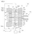
図1に示すように、成形装置100は、射出成形を行って成形品MPを作製する本体部分である射出成形機10と、射出成形機10から成形品MPを取り出す付属部分である取出装置20と、成形装置100を構成する各部の動作を統括的に制御する制御装置30とを備える。
射出成形機10は、横型の成形機であり、射出成形用金型40と、固定盤11と、可動盤12と、型締め盤13と、開閉駆動装置15と、射出装置16とを備える。射出成形機10には、これに付随して減圧装置46、金型温度調節機47等も設けられている。射出成形機10は、固定盤11と可動盤12との間に射出成形用金型40を構成する第1金型41と第2金型42とを挟持して両金型41,42を型締めすることにより成形を可能にする。
固定盤11は、可動盤12に対向して支持フレーム14の略中央に固定され、取出装置20をその上部に支持する。固定盤11の内側11aは、可動盤12の内側12aに対向しており、第1金型41を着脱可能に支持している。固定盤11には、後述するノズル16dを通す開口11bが形成されている。なお、固定盤11は、タイバーを介して型締め盤13に固定されており、成形時の型締めの圧力に耐え得るようになっている。
可動盤12は、リニアガイド15aによって固定盤11に対して進退移動可能に支持されている。可動盤12の内側12aは、固定盤11の内側11aに対向しており、第2金型42を着脱可能に支持している。なお、可動盤12には、エジェクター駆動部45が組み込まれている。このエジェクター駆動部45は、第2金型42内の成形品MPを離型するために第1金型41側に押し出すためのものである。
型締め盤13は、支持フレーム14の端部に固定されている。型締め盤13は、型締めに際して、開閉駆動装置15の動力伝達部15dを介して可動盤12をその背後から支持する。
開閉駆動装置15は、リニアガイド15aと、動力伝達部15dと、アクチュエーター15eとを備える。リニアガイド15aは、可動盤12を支持しつつ、固定盤11に対する進退方向に関して可動盤12の滑らかな往復移動を可能にしている。動力伝達部15dは、制御装置30の制御下で動作するアクチュエーター15eからの駆動力を受けて伸縮する。これにより、型締め盤13に対して可動盤12が近接したり離間したり自在に進退移動する。結果的に、固定盤11と可動盤12とを互いに近接又は離間させることができ、第1金型41と第2金型42との型締め又は型開きを行うことができる。
射出装置16は、シリンダー16a、原料貯留部16b、スクリュー駆動部16c等を備える。射出装置16は、制御装置30の制御下で適当なタイミングで動作するものであり、樹脂射出用のノズル16dから温度制御された状態で溶融樹脂(被射出溶融物)を射出することができる。射出装置16は、第1金型41と第2金型42とを型締めした状態において、固定盤11の開口11bを介して後述するスプルー口部65(図2B参照)にノズル16dを接触させることにより、後述する流路空間FC(図2B参照)に対してシリンダー16a中の溶融樹脂を所望のタイミング及び圧力で射出・供給することができる。
射出成形機10に付随して設けられた減圧装置46は、減圧用の真空装置46aと、第1金型41の側面41s(図2A参照)に連結される配管46bとを備える。減圧装置46は、制御装置30の制御下で適当なタイミングで動作するものであり、両金型41,42間に形成された成形空間CV(図2B参照)等から気体を吸引する減圧を行う。
射出成形機10に付随して設けられた金型温度調節機47は、両金型41,42中に温度制御された熱媒体を循環させる。これにより、成形時に両金型41,42の温度を適切な温度に保つことができる。
取出装置20は、成形品MPを把持することができるハンド21と、ハンド21を3次元的に移動させる3次元駆動装置22とを備える。取出装置20は、制御装置30の制御下で適当なタイミングで動作するものであり、第1金型41と第2金型42とを離間させて型開きした後に、第2金型42に残る成形品MPを把持して外部に搬出する役割を有する。
制御装置30は、開閉制御部31と、射出装置制御部32と、エジェクター制御部33と、取出装置制御部34と、減圧制御部35とを備える。開閉制御部31は、アクチュエーター15eを動作させることによって両金型41,42の型閉じ、型締め、型開き等を可能にする。射出装置制御部32は、スクリュー駆動部16c等を動作させることによって両金型41,42間に形成された成形空間CV中に所望の圧力で溶融樹脂を注入させる。エジェクター制御部33は、エジェクター駆動部45を動作させることによって型開き時に第2金型42に残る成形品MPを第2金型42内から押し出させて離型を行わせる。取出装置制御部34は、取出装置20を動作させることによって型開き及び離型後に第2金型42に残る成形品MPを把持して射出成形機10外に搬出させる。減圧制御部35は、減圧装置46を動作させることによって溶融樹脂の注入前の成形空間CVを減圧する。
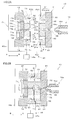
以下、射出成形用金型40について詳しく説明する。図2A等に示すように、射出成形用金型40のうち可動側の第2金型42は、AB方向に往復移動可能になっている。この第2金型42を固定側の第1金型41に向けて移動させ、両金型41,42を型合わせ面すなわちパーティング面PS1,PS2で型合わせして型締めすることにより、図2Bに示すように、光学素子を成形するための成形空間CVと、これに溶融樹脂を供給するための流路である流路空間FCとが形成される。
第1金型41は、固定金型であり、内側すなわちパーティング面PS1側に配置される型板61と、外側すなわち図1の固定盤11側に配置される取付板64とを備える。このうち、型板61は、複数の部分に分割された分割構造を有するものとなっており、分割された部分として、型本体としてのコア部62と、型本体を囲む周辺部63とを有している。
型板61のうち周辺部63は、金属製の板状の部材であり、複数のコア部62を挿入する複数のコア孔61aと、外部からの溶融樹脂を内部に供給するためのスプルー孔61bとを備える。各コア孔61aには、コア部62が挿入されており、コア部62の先端面は、光学素子の光学機能部を形成するための凹部61eとなっている。
なお、周辺部63の内部には、成形時に金型の温度を適切な温度に保つため、金型温度調節機47に接続される部分として、熱媒体を流通させる温調流路、加熱用のヒーター、温度監視用の温度計等が形成されているが、説明の簡単のため図示を省略している。
取付板64は、金属製の板状の部材であり、型板61を背後から支持している。取付板64は、型板61の周辺部63に設けたスプルー孔61bを延長するように接続されたスプルー孔64bを有し、スプルー孔64bの根元側には、射出装置16のノズル16dの先端部を接触させるスプルー口部65が形成されている。
第2金型42は、可動金型であり、内側すなわちパーティング面PS2側に配置される型板71と、外側すなわち図1の可動盤12側に配置される取付板74と、取付板74に埋め込むように形成されたエジェクター部材75とを備える。このうち、型板71は、複数の部分に分割された分割構造を有するものとなっており、分割された部分として、型本体としてのコア部72と、型本体を囲む周辺部73とを有している。
型板71のうち周辺部73は、金属製の板状の部材であり、複数のコア部72を挿入する複数のコア孔71aと、スプルー孔61bに対向するコールドスラグ71bとを備える。各コア孔71aには、コア部72が挿入されており、コア部72の先端面は、光学素子の光学機能部を形成するための凹部71eとなっている。周辺部73には、エジェクター部材75を構成するエジェクターピン75aを通すピン孔71gも形成されている。
なお、周辺部73の内部には、成形時に金型の温度を適切な温度に保つため、金型温度調節機47に接続される部分として、熱媒体を流通させる温調流路、加熱用のヒーター、温度監視用の温度計等が形成されているが、説明の簡単のため図示を省略している。
取付板74は、金属製の板状の部材であり、型板71を背後から支持している。取付板74は、エジェクター部材75を構成するエジェクターピン75a,75bを通すピン孔74g,74hを備える。
エジェクター部材75は、エジェクターピン75a,75bと、エジェクター板75dとを有する機械的な機構であり、図1のエジェクター駆動部45に駆動されて動作する。エジェクターピン75a,75bは、エジェクター板75dに連結されており、型板71のピン孔71g及び取付板74のピン孔74g,74h内で一括して進退移動させることができる。エジェクター部材75を前進状態とした場合、エジェクターピン75a,75bが前進し、このうち中央のエジェクターピン75aが型板71の周辺部73に設けたコールドスラグ71bの底部に突起し、他のエジェクターピン75bがコア部72を押してパーティング面PS2から突出させる。逆に、エジェクター部材75を後退状態とした場合、エジェクターピン75a,75bが後退し、このうち中央のエジェクターピン75aが型板71の周辺部73に設けたコールドスラグ71bの底部に引っ込み、エジェクターピン75bが引っ込んでコア部72の後退を許容する。なお、コア部72は、不図示のバネ等を付随させた構造を有しており、エジェクターピン75aから前進させる付勢力を受けなくなった場合、後退してコア孔71aの奥に収納される。
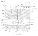
図3を参照して、第1金型41に設けた減圧路81と、第2金型42に設けた通気孔82とについて説明する。
第1金型41には、型締めによって形成される各成形空間CVを減圧装置46の配管46bに連通させるための減圧路81が形成されている。この減圧路81は、第1金型41の型板61を構成する周辺部63内に埋め込まれた孔状の第1部分81aと、型板61の周辺部63のパーティング面PS1に露出する溝状の第2部分81bとを有する。第1部分81aは、例えば円形断面の流路であり、一端の気体排出口83aにおいて減圧装置46に延びる配管46bに接続されており、他端において第2部分81bに連通している。第2部分81bは、第2金型42を第1金型41に所定圧力で付勢した型締め状態で、第2金型42の型板71に設けた型面部分71fと協働して半円断面の流路を形成する。第2部分81bによる流路の一端は、上記のように第1部分81aに接続されており、第2部分81bによる流路の他端は、成形空間CVの周辺側又は外側に延びる隙間状のベント部CVaに接続されている。つまり、成形空間CVは、減圧路81の第1部分81aと第2部分81bとを介して減圧装置46の配管46bに連通しており、図2に示す減圧装置46の真空装置46aを動作させることにより、成形空間CVを所望のタイミングで所望の程度に減圧することができる。
第2金型42には、コア部72の側面72sとコア孔71aの内壁71sとの隙間GAを減圧路81を介して減圧装置46の配管46bに連通させるための通気孔82が形成されている。この通気孔82は、第2金型42の型板71の周辺部73内に埋め込まれた例えば円形断面の流路であり、一端の気体排出口84aにおいて減圧路81の第2部分81bに接続されており、他端の気体取入口84bにおいてコア部72及びコア孔71a間の隙間GAに連通している。つまり、コア部72及びコア孔71aの隙間GAは、減圧路81の第1部分81aと第2部分81bとを介して減圧装置46の配管46bに連通しており、減圧装置46の真空装置46aを動作させて成形空間CVを減圧する際に、併せて隙間GAに溜まった空気を第2金型42外に排出することができ、隙間GAに溜まった空気が成形空間CVに流れ込んで溶融樹脂にエア溜まりが形成されることを防止している。
ここで、通気孔82の気体取入口84bは、コア孔71aの内壁71sであって、AB方向の中間付近に形成されている。また、通気孔82の断面サイズは、コア部72及びコア孔71a間の隙間GAのサイズよりも大きくなっている。つまり、通気孔82の気体取入口84b等の直径は、コア部72及びコア孔71a間の隙間GAの隙間幅よりも大きくなっている。このように通気孔82の断面サイズを大きくすることで、通気孔82による隙間GAに存在する気体の排気効率を高めることができる。
なお、第1金型41と第2金型42とを型締めしたとき、第1金型41に組み込んだコア部62の凹部61eと、第2金型42に組み込んだコア部72の凹部71eとの間に光学素子を成形するための成形空間CVが形成され、第1金型41の型板61の型面に設けた型面部分61rと、第2金型42の型板71の型面に設けた型面部分71rとの間にランナー空間RUが形成される。ランナー空間RUは、図2Bに示す流路空間FCの一部となっており、スプルー孔61b(図2A参照)に連通している。
成形空間CVに望む型板61側の第1転写面S1は、成形空間CVに望む型板71側の第2転写面S2よりも浅くなっている。具体的には、両金型41,42のパーティング面PS1,PS2から第1転写面S1の頂点までの距離W1は、パーティング面PS1,PS2から第2転写面S2の頂点までの距離W2よりも小さくなっている。このため、射出成形時には、深い第2転写面S2側にエア溜まりが発生しやすくなっている。このような事情から、本実施形態では、第2転写面S2のある第2金型42の型板71に設けた周辺部73に通気孔82を形成して、排気の確実性を高めている。
図4は、図2B等に示す射出成形用金型40の変形例を示している。この場合、第1金型41にも、コア部62の側面62sとコア孔61aの内壁61sとの隙間GAを減圧路81を介して減圧装置46の配管46bに連通させるための通気孔182が形成されている。この通気孔182は、第1金型41の型板61の周辺部63内に埋め込まれた例えば円形断面の流路であり、一端の気体排出口84aにおいて減圧路81に接続されており、他端の気体取入口84bにおいてコア部62及びコア孔61a間の隙間GAに連通している。つまり、コア部62及びコア孔61aの隙間GAは、減圧路81の第1部分81aと第2部分81bとを介して減圧装置46の配管46bに連通しており、減圧装置46の真空装置46aを動作させて成形空間CVを減圧する際に、併せてコア部62に隣接する隙間GAに溜まった空気を第1金型41外に排出することができる。
以下、図1等に示す成形装置100を用いた成形品MPすなわち光学素子の製造方法について説明する。まず、金型温度調節機47により、両金型41,42を成形に適する温度まで加熱する。次に、開閉駆動装置15を動作させ、可動盤12を前進させて型閉じを開始させる(型閉じ工程)。開閉駆動装置15の閉動作を継続することにより、第1金型41と第2金型42とを必要な圧力で締め付ける型締めが行われる。次に、減圧装置46を動作させ、金型41,42間に形成された成形空間CVから気体を吸引して成形空間CVを減圧状態に保つ(主減圧工程)。この際、減圧路81に連結された通気孔82,182を介してコア部72,62の周囲の隙間GAに溜まった空気を金型42,41外に排出する(補助減圧工程)。この状態で、射出成形機10において、射出装置16を動作させて、型締めされた第1金型41と第2金型42との間の成形空間CV中に、必要な圧力で溶融樹脂を注入する射出を行わせる(射出工程)。そして、射出成形機10は、成形空間CV中の樹脂圧を保つ。なお、溶融樹脂を成形空間CVに導入した後は、成形空間CV中の溶融樹脂が放熱によって徐々に冷却されるので、かかる冷却にともなって溶融樹脂が固化し成形が完了するのを待つ。次に、射出成形機10において、開閉駆動装置15を動作させて、可動盤12を後退させる型開きが行われる(型開き工程)。これに伴って、第2金型42が後退し、第1金型41と第2金型42とが離間する。次に、射出成形機10において、エジェクター駆動部45を動作させ、エジェクターピン75a,75b等の前進によって、光学素子を含む成形品MPの突き出しを行わせる。この結果、成形品MPのうち光学素子は、第1金型41側に押し出されて第2金型42から離型される(離型工程)。最後に、取出装置20を動作させて、突き出された成形品MPの適所をハンド21で把持して外部に搬出する(取出し工程)。
以上のように、本実施形態の射出成形用金型40によれば、型本体であるコア部62,72と周辺部63,73との隙間GAに連通する通気孔82,182を備えるので、隙間GAの反対側から通気孔82,182を減圧することにより、コア部62,72と周辺部63,73との隙間GAに存在する気体を外部に排出させることができる。つまり、成形空間CV中に溶融樹脂を射出して成形空間CVを充填する準備として減圧路81を介して成形空間CV内を減圧する際に、コア部62,72と周辺部63,73との隙間GAに存在する気体が成形空間CV内へ侵入することを防止できるので、成形品MPの特に成形空間CVに対応する製品部分に気体が含まれてエア溜まり等の外観不良が発生してしまうことを確実に防止できる。また、成形空間CVからの空気の排出がスムーズになる結果として、成形品MPの形状の転写性が良くなる。さらに、気体排出の効率を高めて成形品MPの製造のサイクルタイムを短縮できるといった効果もある。
なお、本実施形態において、成形空間CVの周辺側又は外側にベント部CVaを設けているが、ベント部CVaを設けずに、コア部62の端面とコア部72端面との近接した隙間から成形空間CVを減圧してもよい。つまり、射出成形用金型40に通気孔82を設けることにより、成形空間CVの周辺に設けられることがあったエアベントのようなガス排出機構が不要になる。また、成形空間CVの周辺側又は外側に延びる減圧路81の第2部分81bによる流路の他端を塞いで、成形空間CVを間接的に減圧してもよい。
〔第2実施形態〕
以下、第2実施形態の射出成形用金型等について説明する。第2実施形態の射出成形用金型は、第1実施形態の射出成形用金型等を変形したものであり、特に説明しない部分は、第1実施形態の射出成形用金型等と同様であるものとする。
以下、第2実施形態の射出成形用金型等について説明する。第2実施形態の射出成形用金型は、第1実施形態の射出成形用金型等を変形したものであり、特に説明しない部分は、第1実施形態の射出成形用金型等と同様であるものとする。
図5に示すように、第2実施形態の射出成形用金型40は、成形空間CV内を減圧する減圧路81と、コア部72と型板71との隙間GAに存在する気体を排出するための通気孔282とが別系統で独立している。具体的に説明すると、通気孔282は、第2金型42の型板71の周辺部73内に埋め込まれた例えば円形断面の流路であり、側面42sまで延びる一端の気体排出口84aにおいて減圧装置46の配管46bに連通しており、他端の気体取入口84bにおいてコア部72及びコア孔71a間の隙間GAに連通している。減圧装置46の真空装置46aを動作させることにより、コア部72に隣接する隙間GAに溜まった空気を第2金型42外に排出することができる。なお、図面では、減圧路81と通気孔282とに共通する配管46bが示されているが、減圧路81と通気孔282とに独立した配管を接続することもでき、この場合、減圧路81と通気孔282との独立性をより高めることができる。
以上の第2実施形態において、図4と同様に、第1金型41の型板61におけるコア部62の周囲に連通する通気孔182を設けることもできる。
〔第3実施形態〕
以下、第3実施形態の射出成形用金型等について説明する。第3実施形態の射出成形用金型は、第1実施形態の射出成形用金型等を変形したものであり、特に説明しない部分は、第1実施形態の射出成形用金型等と同様であるものとする。
以下、第3実施形態の射出成形用金型等について説明する。第3実施形態の射出成形用金型は、第1実施形態の射出成形用金型等を変形したものであり、特に説明しない部分は、第1実施形態の射出成形用金型等と同様であるものとする。
図6に示すように、第3実施形態の射出成形用金型40では、コア部72と周辺部73との隙間GAに存在する気体を排出するための通気孔382がコア部72の根元側に連通している。具体的に説明すると、通気孔382は、第2金型42の取付板74内に埋め込まれた例えば円形断面の流路であり、側面42sまで延びる一端の気体排出口84aにおいて減圧装置46の配管46bに連通しており、他端の気体取入口84bにおいてコア部72の裏側の根元部72rを介してコア部72及びコア孔71a間の隙間GAに連通している。減圧装置46の真空装置46aを動作させることにより、コア部72に隣接する隙間GAに溜まった空気を第2金型42外に排出することができる。なお、図面では、減圧路81と通気孔382とに共通する配管46bが示されているが、減圧路81と通気孔282とに独立した配管を接続することもできる。
本実施形態のように、通気孔382をコア部72の根元側に連通させる場合、隙間GAに存在する気体を第1金型42と第2金型42との合わせ面であるパーティング面PS1,PS2からから離れる方向に一様に吸引することになり、成形品MPの特に成形空間CVに対応する製品部分にエア溜まりが発生することをより確実に防止できる。
以上の第3実施形態において、図4と同様に、第1金型41の型板61におけるコア部62の周囲に連通する通気孔182を設けることもできる。
〔第4実施形態〕
以下、第4実施形態の射出成形用金型等について説明する。第4実施形態の射出成形用金型は、第1実施形態の射出成形用金型等を変形したものであり、特に説明しない部分は、第1実施形態の射出成形用金型等と同様であるものとする。
以下、第4実施形態の射出成形用金型等について説明する。第4実施形態の射出成形用金型は、第1実施形態の射出成形用金型等を変形したものであり、特に説明しない部分は、第1実施形態の射出成形用金型等と同様であるものとする。
図7に示すように、第4実施形態の射出成形用金型40は、第1金型41側に、成形空間CV内を減圧する減圧路81と、コア部62と周辺部63との隙間GAに存在する気体を排出するための通気孔482とが設けられている。通気孔482は、一端において減圧路81に連通しており、他端においてコア部62に隣接する隙間GAに連通している。
本実施形態の場合、成形空間CVに望む型板61側の凹部461eに設けた第1転写面S1は、成形空間CVに望む型板71側の凹部471eに設けた第2転写面S2よりも深くなっている。このため、射出成形時には、深い第1転写面S1側に空気が溜まりやすくなっている。このような事情から、本実施形態では、第1転写面S1のある第1金型41の型板61に通気孔482を形成して、排気の確実性を高めている。
〔第5実施形態〕
以下、第5実施形態の射出成形用金型等について説明する。第5実施形態の射出成形用金型は、第1実施形態の射出成形用金型等を変形したものであり、特に説明しない部分は、第1実施形態の射出成形用金型等と同様であるものとする。
以下、第5実施形態の射出成形用金型等について説明する。第5実施形態の射出成形用金型は、第1実施形態の射出成形用金型等を変形したものであり、特に説明しない部分は、第1実施形態の射出成形用金型等と同様であるものとする。
図8Aに示すように、第5実施形態の射出成形用金型40の第2金型42の場合、コア部572が、内側に配置される軸状の第1の型部分2aと、当該第1の型部分2aの周囲に配置される筒状の第2の型部分2bとを有する。
図8Bに示すように、コア部572のうち外側の第2の型部分2b内に埋め込むように、通気孔582が形成されている。この通気孔582は、コア部572の内側を構成する第1の型部分2aの外側面2tと、コア部572の外側を構成する第2の型部分2bの内壁3tとの隙間GA1を、減圧路81を介して減圧装置46の配管46bに連通させる。また、通気孔582は、コア部572の外側を構成する第2の型部分2bの外側面2sと、周辺部73に設けたコア孔71aの内壁3sとの隙間GA2を、減圧路81を介して減圧装置46の配管46bに連通させる。このため、通気孔582は、第2の型部分2bの軸に沿って延び、一端の気体排出口84aにおいて減圧路81の第2部分81b又はベント部CVaに接続されており、他端の気体取入口84bにおいて一対の型部分2a,2b間の隙間GA1に連通し、他端の気体取入口84cにおいて第2の型部分2b及び周辺部73間の隙間GA2に連通している。
本実施形態の射出成形用金型40によれば、コア部572を構成する一対の型部分2a,2bの隙間GA1に存在する気体を外部に排出させることができ、コア部572と周辺部73との隙間GA2に存在する気体を外部に排出させることができる。よって、成形空間CV中に溶融樹脂を射出して成形空間CVを充填する準備として減圧路81を介して成形空間CV内を減圧する際に、コア部572周辺の隙間GA1,GA2に存在する気体が成形空間CV内へ侵入することを防止できるので、成形品MPの特に成形空間CVに対応する製品部分に気体が含まれてエア溜まり等の外観不良が発生してしまうことを確実に防止できる。また、成形空間CVからの空気の排出がスムーズになって成形品MPの形状の転写性が良くなり、エアベントのようなガス排出機構が不要になるとともに、気体排出の効率を高めて成形品MPの製造のサイクルタイムを短縮できる。
なお、本実施形態において、通気孔582の他端に気体取入口84cを設けているが、当該気体取入口84cをふさいでもよい。この場合、通気孔582は、コア部572を構成する一対の型部分2a,2bの隙間GA1に存在する気体を外部に排出させる。
以上実施形態に即して本発明を説明したが、本発明は、上記実施形態に限定されるものではなく、様々な変形が可能である。例えば、上記実施形態において、第1金型41及び第2金型42で構成される射出成形用金型に設ける成形空間CVの形状は、様々な形状とすることができる。すなわち、凹部61e,71e等によって形成される成形空間CVの形状は、単なる例示であり、各種の光学素子の用途等に応じて適宜変更することができる。
以上では、減圧装置46によって減圧路81経由で成形空間CVを減圧状態に保ち、かつ、通気孔82,182,282,382,482,582経由での隙間GAの気体を外部に排出した状態で、射出成形機10による射出工程を行っている。このような射出工程に際しては、減圧装置46の運転を継続していてもよいが、 減圧装置46の運転を停止してもよい。
また、型閉じ工程や型締め工程後に主減圧工程や補助減圧工を行う必要はなく、両金型41,42を近接させる型閉じの開始前後から、減圧装置46による主減圧工程や補助減圧工を実施することができる。
成形空間CVに充填する樹脂は、熱可塑性樹脂に限らず、熱硬化性樹脂その他の各種材料とすることができる。
射出成形機10は、横型に限らず、第1金型41と第2金型42とを上下に配置する竪型の成形機とすることができる。
Claims (13)
- 第1金型と第2金型とを備え、前記第1金型と前記第2金型とを型閉じすることによって成形空間を形成する射出成形用金型であって、
前記第1金型と前記第2金型とのうち少なくとも一方は、分割された部分として、前記成形空間に対向する型本体と当該型本体を囲む周辺部とを有し、
前記成形空間に連通する減圧路と、前記型本体と前記周辺部との隙間に連通する通気孔とが設けられている射出成形用金型。 - 前記通気孔の断面のサイズは、前記型本体と前記周辺部との隙間幅よりも大きい、請求項1に記載の射出成形用金型。
- 前記通気孔の一端に設けた気体取入口は、前記周辺部の内壁に連通している、請求項1及び2のいずれか一項に記載の射出成形用金型。
- 前記通気孔の他端に設けた気体排出口は、前記減圧路の途中に連通している、請求項1及び2のいずれか一項に記載の射出成形用金型。
- 前記通気孔は、前記減圧路から独立して金型外に引き出されている、請求項1及び2のいずれか一項に記載の射出成形用金型。
- 前記通気孔の一端に設けた気体取入口は、前記型本体の根元側に連通している、請求項1及び2のいずれか一項に記載の射出成形用金型。
- 前記第1金型は、前記第2金型よりも浅い転写面を有し、前記通気孔は、前記第2金型に設けた前記型本体と前記周辺部との隙間に連通する、請求項1に記載の射出成形用金型。
- 前記減圧路を介して前記成形空間内を減圧するとともに、前記通気孔を介して前記型本体と前記周辺部との隙間を減圧する減圧装置を備える、請求項1に記載の射出成形用金型。
- 前記型本体は、内側に配置される第1の型部分と、当該第1の型部分の周囲に配置される筒状の第2の型部分とを有し、
前記通気孔は、前記型本体の前記第1の型部分と前記第2の型部分との隙間に連通する、請求項1に記載の射出成形用金型。 - 前記通気孔は、さらに前記型本体の前記第2の型部分と前記周辺部との隙間に連通する、請求項9に記載の射出成形用金型。
- 第1金型と第2金型とを備え、前記第1金型と前記第2金型とを型閉じすることによって成形空間を形成する射出成形用金型であって、
前記第1金型と前記第2金型とのうち少なくとも一方は、分割された部分として、前記成形空間に対向する型本体と、当該型本体を囲む周辺部とを有し、
前記型本体は、内側に配置される第1の型部分と、当該第1の型部分の周囲に配置される筒状の第2の型部分とを有し、
前記成形空間に連通する減圧路と、前記型本体の前記第1の型部分と前記型本体の前記第2の型部分との隙間に連通する通気孔とが設けられている射出成形用金型。 - 前記通気孔は、さらに前記型本体の前記第2の型部分と前記周辺部との隙間に連通する、請求項11に記載の射出成形用金型。
- 射出成形用金型を構成する第1金型と第2金型とを型閉じすることによって、前記射出成形用金型中に成形空間を形成する型閉じ工程と、
前記成形空間に連通する減圧路を介して前記成形空間内を減圧する主減圧工程と、
前記第1金型と前記第2金型とのうち少なくとも一方において分割された部分として設けられた前記成形空間に対向する型本体と当該型本体を囲む周辺部との隙間を、当該隙間に連通する通気孔を介して減圧する補助減圧工程と、
前記射出成形用金型の前記成形空間中に被射出溶融物を射出して前記成形空間を充填する射出工程と、
を備える射出成形方法。
Applications Claiming Priority (2)
| Application Number | Priority Date | Filing Date | Title |
|---|---|---|---|
| JP2011-124691 | 2011-06-02 | ||
| JP2011124691 | 2011-06-02 |
Publications (1)
| Publication Number | Publication Date |
|---|---|
| WO2012165593A1 true WO2012165593A1 (ja) | 2012-12-06 |
Family
ID=47259445
Family Applications (1)
| Application Number | Title | Priority Date | Filing Date |
|---|---|---|---|
| PCT/JP2012/064203 Ceased WO2012165593A1 (ja) | 2011-06-02 | 2012-05-31 | 射出成形用金型及び射出成形方法 |
Country Status (1)
| Country | Link |
|---|---|
| WO (1) | WO2012165593A1 (ja) |
Cited By (1)
| Publication number | Priority date | Publication date | Assignee | Title |
|---|---|---|---|---|
| WO2015053641A1 (en) * | 2013-10-08 | 2015-04-16 | Zachodniopomorski Uniwersytet Technologiczny W Szczecinie | Pro-healthy food product |
Citations (4)
| Publication number | Priority date | Publication date | Assignee | Title |
|---|---|---|---|---|
| JPS6490716A (en) * | 1987-10-02 | 1989-04-07 | Hitachi Ltd | Molding device of plastic concave lens |
| JP2000343565A (ja) * | 1999-06-08 | 2000-12-12 | Sony Corp | 金型装置 |
| JP2008273070A (ja) * | 2007-04-28 | 2008-11-13 | Meiki Co Ltd | 導光板の成形金型および導光板の成形方法 |
| JP2010082838A (ja) * | 2008-09-29 | 2010-04-15 | Konica Minolta Opto Inc | レンズ製造方法 |
-
2012
- 2012-05-31 WO PCT/JP2012/064203 patent/WO2012165593A1/ja not_active Ceased
Patent Citations (4)
| Publication number | Priority date | Publication date | Assignee | Title |
|---|---|---|---|---|
| JPS6490716A (en) * | 1987-10-02 | 1989-04-07 | Hitachi Ltd | Molding device of plastic concave lens |
| JP2000343565A (ja) * | 1999-06-08 | 2000-12-12 | Sony Corp | 金型装置 |
| JP2008273070A (ja) * | 2007-04-28 | 2008-11-13 | Meiki Co Ltd | 導光板の成形金型および導光板の成形方法 |
| JP2010082838A (ja) * | 2008-09-29 | 2010-04-15 | Konica Minolta Opto Inc | レンズ製造方法 |
Cited By (1)
| Publication number | Priority date | Publication date | Assignee | Title |
|---|---|---|---|---|
| WO2015053641A1 (en) * | 2013-10-08 | 2015-04-16 | Zachodniopomorski Uniwersytet Technologiczny W Szczecinie | Pro-healthy food product |
Similar Documents
| Publication | Publication Date | Title |
|---|---|---|
| JP5723617B2 (ja) | 射出成形装置、成形型、及び射出成形品の製造方法 | |
| CN110248793B (zh) | 成型用模具 | |
| WO2010061728A1 (ja) | 光学素子の製造方法及び成形金型 | |
| JP6664476B2 (ja) | 射出圧縮成形金型および射出圧縮成形方法 | |
| WO2012165593A1 (ja) | 射出成形用金型及び射出成形方法 | |
| CN101980847A (zh) | 光学元件成形模具及光学元件的制造方法 | |
| CN110667120A (zh) | 制造多个相互焊接的塑料模制件形成的构件的设备和方法 | |
| WO2012172669A1 (ja) | 射出成形用型装置および射出成形機 | |
| JP2010105168A (ja) | 多材射出成形装置および多材射出成形方法ならびに多材射出成形金型 | |
| JP5071794B2 (ja) | 薄板状光学用成形品の射出プレス成形方法 | |
| JP5595446B2 (ja) | 金属射出成形機の金型装置 | |
| JP2018103393A (ja) | 射出成形機及び射出成形方法 | |
| JP2009202549A (ja) | 樹脂成形品の製造方法 | |
| JP6590649B2 (ja) | 射出成型装置、及びその方法 | |
| JP2014046537A (ja) | スプルーブッシュ及び成形金型 | |
| JP4808177B2 (ja) | 成形体の製造方法および装置 | |
| JP6264113B2 (ja) | 光学素子用の成形金型 | |
| JP2013212593A (ja) | 成形品の製造方法及び製造装置 | |
| JP4218836B2 (ja) | 離型剤の塗布方法および射出成形用金型 | |
| EP3708332B1 (en) | Device for demoulding negatives in thermoplastic injection moulds | |
| JP2009143051A (ja) | 射出成形機の突出し機構 | |
| JP2010162798A (ja) | 射出成形装置及び方法 | |
| JP2006297872A (ja) | 金型装置 | |
| JP2008284704A (ja) | 成形型および光学素子の製造方法 | |
| JP2007190871A (ja) | 射出成形体の成形方法、並びに射出成形装置 |
Legal Events
| Date | Code | Title | Description |
|---|---|---|---|
| 121 | Ep: the epo has been informed by wipo that ep was designated in this application |
Ref document number: 12793936 Country of ref document: EP Kind code of ref document: A1 |
|
| NENP | Non-entry into the national phase |
Ref country code: DE |
|
| 122 | Ep: pct application non-entry in european phase |
Ref document number: 12793936 Country of ref document: EP Kind code of ref document: A1 |
|
| NENP | Non-entry into the national phase |
Ref country code: JP |