WO2012141064A1 - 流量制御弁およびこれを備えた血圧情報測定装置 - Google Patents
流量制御弁およびこれを備えた血圧情報測定装置 Download PDFInfo
- Publication number
- WO2012141064A1 WO2012141064A1 PCT/JP2012/059325 JP2012059325W WO2012141064A1 WO 2012141064 A1 WO2012141064 A1 WO 2012141064A1 JP 2012059325 W JP2012059325 W JP 2012059325W WO 2012141064 A1 WO2012141064 A1 WO 2012141064A1
- Authority
- WO
- WIPO (PCT)
- Prior art keywords
- control valve
- pressure
- valve
- flow control
- flow
- Prior art date
Links
- 230000036772 blood pressure Effects 0.000 title claims description 66
- 238000005259 measurement Methods 0.000 title claims description 35
- 239000012530 fluid Substances 0.000 claims abstract description 51
- 230000008859 change Effects 0.000 claims abstract description 25
- 230000006835 compression Effects 0.000 claims description 64
- 238000007906 compression Methods 0.000 claims description 64
- 238000000034 method Methods 0.000 claims description 36
- 230000035488 systolic blood pressure Effects 0.000 claims description 13
- 230000035487 diastolic blood pressure Effects 0.000 claims description 12
- 238000000691 measurement method Methods 0.000 claims description 12
- 238000007599 discharging Methods 0.000 claims description 7
- 238000009530 blood pressure measurement Methods 0.000 claims description 3
- 230000033001 locomotion Effects 0.000 abstract description 40
- 238000006073 displacement reaction Methods 0.000 abstract description 10
- 238000005192 partition Methods 0.000 abstract description 2
- 230000008569 process Effects 0.000 description 29
- 238000004891 communication Methods 0.000 description 22
- 230000004048 modification Effects 0.000 description 22
- 238000012986 modification Methods 0.000 description 22
- 238000005086 pumping Methods 0.000 description 16
- 230000001276 controlling effect Effects 0.000 description 11
- 230000006870 function Effects 0.000 description 11
- 230000000694 effects Effects 0.000 description 10
- 230000009467 reduction Effects 0.000 description 10
- 230000006837 decompression Effects 0.000 description 9
- 230000010355 oscillation Effects 0.000 description 9
- 230000002093 peripheral effect Effects 0.000 description 9
- 238000005452 bending Methods 0.000 description 7
- 210000004712 air sac Anatomy 0.000 description 6
- 238000006243 chemical reaction Methods 0.000 description 5
- 230000007423 decrease Effects 0.000 description 4
- 230000003247 decreasing effect Effects 0.000 description 4
- 239000010408 film Substances 0.000 description 4
- 238000012545 processing Methods 0.000 description 4
- 238000011946 reduction process Methods 0.000 description 4
- 238000007789 sealing Methods 0.000 description 4
- 206010003210 Arteriosclerosis Diseases 0.000 description 3
- 208000011775 arteriosclerosis disease Diseases 0.000 description 3
- 230000005540 biological transmission Effects 0.000 description 3
- 238000010586 diagram Methods 0.000 description 3
- 239000007789 gas Substances 0.000 description 3
- 239000007788 liquid Substances 0.000 description 3
- 229920005989 resin Polymers 0.000 description 3
- 239000011347 resin Substances 0.000 description 3
- 239000000284 extract Substances 0.000 description 2
- 239000000463 material Substances 0.000 description 2
- 230000007246 mechanism Effects 0.000 description 2
- 230000010349 pulsation Effects 0.000 description 2
- 229920002050 silicone resin Polymers 0.000 description 2
- 238000012360 testing method Methods 0.000 description 2
- 239000010409 thin film Substances 0.000 description 2
- 229910000906 Bronze Inorganic materials 0.000 description 1
- 208000024172 Cardiovascular disease Diseases 0.000 description 1
- 206010019280 Heart failures Diseases 0.000 description 1
- OAICVXFJPJFONN-UHFFFAOYSA-N Phosphorus Chemical compound [P] OAICVXFJPJFONN-UHFFFAOYSA-N 0.000 description 1
- 208000006011 Stroke Diseases 0.000 description 1
- 239000000956 alloy Substances 0.000 description 1
- 229910045601 alloy Inorganic materials 0.000 description 1
- 210000001367 artery Anatomy 0.000 description 1
- QVGXLLKOCUKJST-UHFFFAOYSA-N atomic oxygen Chemical compound [O] QVGXLLKOCUKJST-UHFFFAOYSA-N 0.000 description 1
- 230000003416 augmentation Effects 0.000 description 1
- 230000033228 biological regulation Effects 0.000 description 1
- 239000010974 bronze Substances 0.000 description 1
- KUNSUQLRTQLHQQ-UHFFFAOYSA-N copper tin Chemical compound [Cu].[Sn] KUNSUQLRTQLHQQ-UHFFFAOYSA-N 0.000 description 1
- 238000005520 cutting process Methods 0.000 description 1
- 230000003111 delayed effect Effects 0.000 description 1
- 238000001514 detection method Methods 0.000 description 1
- 201000010099 disease Diseases 0.000 description 1
- 208000037265 diseases, disorders, signs and symptoms Diseases 0.000 description 1
- 230000003862 health status Effects 0.000 description 1
- 230000006872 improvement Effects 0.000 description 1
- 239000004973 liquid crystal related substance Substances 0.000 description 1
- 238000004519 manufacturing process Methods 0.000 description 1
- 239000002184 metal Substances 0.000 description 1
- 208000010125 myocardial infarction Diseases 0.000 description 1
- 238000005457 optimization Methods 0.000 description 1
- 239000001301 oxygen Substances 0.000 description 1
- 229910052760 oxygen Inorganic materials 0.000 description 1
- 229920001225 polyester resin Polymers 0.000 description 1
- 239000004645 polyester resin Substances 0.000 description 1
- -1 polyethylene terephthalate Polymers 0.000 description 1
- 229920000139 polyethylene terephthalate Polymers 0.000 description 1
- 239000005020 polyethylene terephthalate Substances 0.000 description 1
- 230000002265 prevention Effects 0.000 description 1
- 230000001105 regulatory effect Effects 0.000 description 1
- 230000004044 response Effects 0.000 description 1
- 230000004043 responsiveness Effects 0.000 description 1
- 238000012502 risk assessment Methods 0.000 description 1
- 230000036962 time dependent Effects 0.000 description 1
- 210000000707 wrist Anatomy 0.000 description 1
Images


Classifications
-
- A—HUMAN NECESSITIES
- A61—MEDICAL OR VETERINARY SCIENCE; HYGIENE
- A61B—DIAGNOSIS; SURGERY; IDENTIFICATION
- A61B5/00—Measuring for diagnostic purposes; Identification of persons
- A61B5/02—Detecting, measuring or recording pulse, heart rate, blood pressure or blood flow; Combined pulse/heart-rate/blood pressure determination; Evaluating a cardiovascular condition not otherwise provided for, e.g. using combinations of techniques provided for in this group with electrocardiography or electroauscultation; Heart catheters for measuring blood pressure
- A61B5/021—Measuring pressure in heart or blood vessels
- A61B5/022—Measuring pressure in heart or blood vessels by applying pressure to close blood vessels, e.g. against the skin; Ophthalmodynamometers
- A61B5/0235—Valves specially adapted therefor
-
- F—MECHANICAL ENGINEERING; LIGHTING; HEATING; WEAPONS; BLASTING
- F16—ENGINEERING ELEMENTS AND UNITS; GENERAL MEASURES FOR PRODUCING AND MAINTAINING EFFECTIVE FUNCTIONING OF MACHINES OR INSTALLATIONS; THERMAL INSULATION IN GENERAL
- F16K—VALVES; TAPS; COCKS; ACTUATING-FLOATS; DEVICES FOR VENTING OR AERATING
- F16K31/00—Actuating devices; Operating means; Releasing devices
- F16K31/004—Actuating devices; Operating means; Releasing devices actuated by piezoelectric means
-
- F—MECHANICAL ENGINEERING; LIGHTING; HEATING; WEAPONS; BLASTING
- F16—ENGINEERING ELEMENTS AND UNITS; GENERAL MEASURES FOR PRODUCING AND MAINTAINING EFFECTIVE FUNCTIONING OF MACHINES OR INSTALLATIONS; THERMAL INSULATION IN GENERAL
- F16K—VALVES; TAPS; COCKS; ACTUATING-FLOATS; DEVICES FOR VENTING OR AERATING
- F16K7/00—Diaphragm valves or cut-off apparatus, e.g. with a member deformed, but not moved bodily, to close the passage ; Pinch valves
- F16K7/12—Diaphragm valves or cut-off apparatus, e.g. with a member deformed, but not moved bodily, to close the passage ; Pinch valves with flat, dished, or bowl-shaped diaphragm
- F16K7/14—Diaphragm valves or cut-off apparatus, e.g. with a member deformed, but not moved bodily, to close the passage ; Pinch valves with flat, dished, or bowl-shaped diaphragm arranged to be deformed against a flat seat
- F16K7/17—Diaphragm valves or cut-off apparatus, e.g. with a member deformed, but not moved bodily, to close the passage ; Pinch valves with flat, dished, or bowl-shaped diaphragm arranged to be deformed against a flat seat the diaphragm being actuated by fluid pressure
-
- G—PHYSICS
- G05—CONTROLLING; REGULATING
- G05D—SYSTEMS FOR CONTROLLING OR REGULATING NON-ELECTRIC VARIABLES
- G05D7/00—Control of flow
- G05D7/005—Control of flow characterised by the use of auxiliary non-electric power combined with the use of electric means
Definitions
- the present invention relates to a flow rate control valve capable of variably controlling the flow rate of a fluid and a blood pressure information measuring apparatus including the same, and more specifically, a flow rate control valve capable of variably controlling the flow rate of a compressed fluid and the flow rate control.
- the present invention relates to a blood pressure information measuring device provided with a valve as a discharge valve for reducing the internal pressure of a fluid bag for compression.
- Measuring the blood pressure information of a subject is very important for knowing the health status of the subject.
- systolic blood pressure values and diastolic blood pressure values which are widely recognized as useful indices for risk analysis of cardiovascular diseases such as stroke, heart failure, and myocardial infarction.
- An attempt to capture the heart load and the degree of arteriosclerosis by measuring the pulse wave of the subject is not limited.
- the blood pressure information measurement device is a device for measuring these blood pressure information, and is expected to be further utilized in the fields of early detection, prevention, treatment, etc. of circulatory system diseases.
- the blood pressure information widely includes various information on the circulatory system such as systolic blood pressure value, diastolic blood pressure value, average blood pressure value, pulse wave, pulse, and various indexes indicating arteriosclerosis.
- a blood pressure information measuring device cuff (hereinafter also simply referred to as a cuff) is used for measuring blood pressure information.
- the cuff means a band-like or annular structure including a fluid bag having a lumen, which can be attached to a part of a living body, and fluid such as gas or liquid is injected into the lumen. By doing so, the fluid bag is inflated to compress the artery, which is used for measuring blood pressure information.
- a blood pressure information measuring device is provided with a pressurizing pump and a discharge valve as a pressure increasing / decreasing mechanism for increasing / decreasing the internal pressure of the fluid bag.
- the discharge valve is for maintaining the internal pressure of the fluid bag pressurized by the pressurizing pump in the closed state and reducing the pressure in the open state.
- a flow rate control valve capable of variably controlling the discharge flow rate by controlling the operation when the internal pressure of the fluid bag is reduced is preferably used.
- Patent Document 1 Japanese Patent Application Laid-Open No. 6-47007
- Patent Document 2 Japanese Patent Application Laid-Open No. 6-47008
- Patent Document 3 Japanese Patent Application Laid-Open No. 2002-5330
- the electromagnetically driven valve includes a housing, a drive shaft having a valve body attached to the tip, a permanent magnet provided on one of the housing and the drive shaft, and an electromagnetic provided on the other of the housing and the drive shaft.
- the drive shaft can be moved along the axial direction by using the electromagnetic force generated in the electromagnetic coil and the repulsive force generated in the permanent magnet when energized to the electromagnetic coil. It is configured.
- the electromagnetically driven valve is provided at the outlet of the fluid bag contained in the cuff. It is arranged so that the valve body provided at the front end of the drive shaft can close and open the discharge port with the movement of the valve body, and thereby the fluid discharged from the fluid bag Is configured to be variably controllable.
- the electromagnetically driven valve moves the drive shaft using the electromagnetic force generated in the electromagnetic coil and the repulsive force generated in the permanent magnet. It is big compared. Therefore, when the electromagnetically driven valve is used as a discharge valve, there arises a problem that the power consumption of the entire blood pressure information measuring device becomes large.
- the electromagnetically driven valve includes a large number of various components such as a permanent magnet and an electromagnetic coil, so that it is relatively expensive and its structure is very complicated and its volume is also large. It ’s big. Therefore, when the electromagnetically driven valve is used as the discharge valve, there arises a problem that the manufacturing cost of the blood pressure information measuring device is reduced, and a problem that the blood pressure information measuring device becomes large or heavy. .
- the electromagnetically driven valve moves the drive shaft by using the electromagnetic force generated in the electromagnetic coil and the repulsive force generated in the permanent magnet. It is relatively difficult to control. Therefore, when the electromagnetically driven valve is used as a discharge valve, there arises a problem that it becomes difficult to precisely control the flow rate of the fluid discharged from the fluid bag.
- the conventional blood pressure information measuring device and the flow rate control valve as the discharge valve provided in the conventional blood pressure information measuring device still have much room for improvement in various aspects as described above.
- the present invention is small, light and inexpensive, can be configured at low cost, has low power consumption, and can easily control the flow rate of fluid, and a blood pressure information measuring device including the flow rate control valve as a discharge valve The purpose is to provide.
- the flow control valve according to the present invention can variably control the flow rate of the fluid, and includes a casing, a diaphragm, and a valve body.
- the casing is provided with an inlet through which the fluid flows and an outlet through which the fluid flows out.
- the diaphragm partitions the space in the casing into a flow space in which the fluid flows and a working space in which a working medium exists.
- the valve body is provided in the diaphragm at a portion facing the inflow port.
- the distance between the valve body and the inflow port is increased by the movement of the valve body due to the displacement of the diaphragm with a change in the internal pressure of the working space. By changing, the flow rate of the fluid flowing into the flow space from the inflow port is adjusted, whereby the flow rate of the fluid flowing out from the outflow port can be variably controlled.
- an area of a portion of the diaphragm that is displaced with an internal pressure change in the working space is larger than an opening area of the inlet.
- the valve body has a size that completely closes the inlet in a state where the distance from the inlet is lost.
- the valve body is preferably composed of an elastic member.
- valve body is made of a member harder than the diaphragm.
- the main surface of the valve body facing the inflow port has minute irregularities.
- an opening through which the working medium is introduced and led out is provided in the casing.
- the flow control valve further includes a pressure generating unit that causes an internal pressure change in the working space by introducing and deriving the working medium through the opening.
- a pressure generating unit that causes an internal pressure change in the working space by introducing and deriving the working medium through the opening.
- it is.
- the pressure generating unit includes a pump that sucks and discharges the working medium.
- the pump when the pump has a forward direction from the suction port side to the discharge port side of the pump, the pressure on the suction port side is on the discharge port side. It is preferable that the pump is configured by a pump capable of discharging the working medium in a direction opposite to the forward direction under a condition lower than the pressure.
- the pump is constituted by a piezoelectric pump that sucks and discharges the working medium by vibrating a vibration plate portion to which a piezoelectric element is assembled. Is preferred.
- the pressure on the suction port side is the discharge port side. It may be configured by a pump that cannot discharge the working medium in a direction opposite to the forward direction under a condition lower than the pressure of the pressure, and in that case, the leakage valve is in communication with the working space. Is preferably provided.
- the casing and the pressure generating unit are integrated by fixing the casing to the housing of the pressure generating unit.
- the fluid flowing into the flow space from the inflow port may be compressed air compressed to a pressure higher than atmospheric pressure.
- the working medium existing in the working space is preferably air having a pressure lower than that of the compressed air.
- the blood pressure information measurement device includes the flow rate control valve according to the present invention as a discharge valve for reducing the internal pressure of the compression fluid bag for compressing the living body.
- the drive of the flow control valve as the discharge valve is controlled so that the internal pressure of the compression fluid bag is slightly reduced, It is preferable that at least the systolic blood pressure value and the diastolic blood pressure value are calculated based on the decompression measurement method. Further, after the measurement is completed, the discharge valve is used as the exhaust valve so that the internal pressure of the compression fluid bag is rapidly decompressed. It is preferable that the driving of the flow rate control valve is controlled.
- the drive of the flow control valve as the discharge valve is controlled so that the internal pressure of the compression fluid bag is slightly increased.
- at least the systolic blood pressure value and the diastolic blood pressure value are calculated based on the pressurization measurement method, and the exhaust valve is configured so that the internal pressure of the compression fluid bag is rapidly reduced after the measurement is completed. It is preferable that the driving of the flow rate control valve is controlled.
- a flow rate control valve capable of easily controlling the flow rate of a fluid, and blood pressure information method measurement including the flow rate control valve as a discharge valve. It can be a device.
- FIG. 1 It is a perspective view which shows the external appearance structure of the blood pressure meter in Embodiment 1 of this invention. It is a figure which shows the structure of the functional block of the sphygmomanometer in Embodiment 1 of this invention. It is a schematic cross section of the flow control valve in Embodiment 1 of this invention. It is a schematic cross section which shows the operation
- FIG. 10 is an enlarged cross-sectional view of a main part showing still another configuration example of the valve unit shown in FIG. 3.
- FIG. 10 shows the operation
- FIG. 14 It is a figure which shows the specific operation
- a so-called upper arm configured to be able to measure a subject's systolic blood pressure value and diastolic blood pressure value by using a cuff attached to the upper arm of the subject as a blood pressure information measuring device.
- An explanation will be given by exemplifying a type sphygmomanometer.
- the same or common parts are denoted by the same reference numerals in the drawings, and description thereof will not be repeated.
- FIG. 1 is a perspective view showing an external structure of a sphygmomanometer according to Embodiment 1 of the present invention
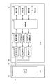
- FIG. 2 is a diagram showing a functional block configuration.
- the sphygmomanometer 1 in the present embodiment includes a main body 10, a cuff 40, and an air tube 50.
- the main body 10 has a box-shaped housing, and has a display unit 21 and an operation unit 23 on an upper surface thereof.
- the main body 10 is used by being placed on a placement surface such as a table at the time of measurement.
- the cuff 40 mainly has a belt-like and bag-like outer cover 41 and a compression air bag 42 as a compression fluid bag contained in the outer cover 41 and has a substantially annular shape as a whole. is doing.
- the cuff 40 is used by being wound around the upper arm of the subject at the time of measurement.
- the air pipe 50 connects the main body 10 and the cuff 40 which are configured separately.
- the main body 10 includes a control unit 20, a memory unit 22, a power supply unit 24, a pressurizing pump 31, and a flow rate control as a discharge valve in addition to the display unit 21 and the operation unit 23 described above. It has a valve 32, a pressure sensor 33, a pressure pump drive circuit 34, a flow control valve drive circuit 35, and an oscillation circuit 36.
- the pressurization pump 31, the flow control valve 32, and the pressure sensor 33 correspond to the compression air system component 30 provided in the sphygmomanometer 1, and in particular, the pressurization pump 31 and the flow control valve 32 are included in the compression air bag 42. It corresponds to a pressure increasing / decreasing mechanism for increasing / decreasing the internal pressure.
- the compression air bag 42 is for compressing the upper arm in the mounted state, and has a lumen inside thereof.
- the compression air bag 42 is connected to each of the pressure pump 31, the flow rate control valve 32, and the pressure sensor 33, which are the compression air system components 30, via the air pipe 50 described above.
- the compression air bag 42 is pressurized and expanded when the pressurizing pump 31 is driven, and its internal pressure is maintained or reduced by controlling the driving of the flow control valve 32 serving as a discharge valve. Or shrink.
- the control unit 20 is configured by, for example, a CPU (Central Processing Unit), and is a means for controlling the entire sphygmomanometer 1.
- the display unit 21 is configured by, for example, an LCD (Liquid Crystal Display), and is a means for displaying measurement results and the like.
- the memory unit 22 is configured by, for example, a ROM (Read-Only Memory) or a RAM (Random-Access Memory), and stores a program for causing the control unit 20 or the like to execute a processing procedure for blood pressure measurement, This is a means for storing measurement results and the like.
- the operation unit 23 is a means for accepting an operation by a subject or the like and inputting an external command to the control unit 20 or the power supply unit 24.
- the power supply unit 24 is means for supplying power to the control unit 20.
- the control unit 20 inputs a control signal for driving the pressurization pump 31 and the flow rate control valve 32 to the pressurization pump drive circuit 34 and the flow rate control valve drive circuit 35, respectively, and displays a blood pressure value as a measurement result. 21 or the memory unit 22.
- the control unit 20 includes a blood pressure information acquisition unit (not shown) that acquires the blood pressure value of the subject based on the pressure value detected by the pressure sensor 33, and the blood pressure value acquired by the blood pressure information measurement unit. Is input to the display unit 21 and the memory unit 22 described above as measurement results.
- the sphygmomanometer 1 may further include an output unit that outputs a blood pressure value as a measurement result to an external device (for example, a PC (Personal Computer) or a printer).
- the output unit for example, a serial communication line or a writing device for various recording media can be used.
- the pressurization pump drive circuit 34 controls the operation of the pressurization pump 31 based on the control signal input from the control unit 20.
- the flow control valve drive circuit 35 controls the opening / closing operation of the flow control valve 32 based on the control signal input from the control unit 20.
- the pressurizing pump 31 is for pressurizing the internal pressure (hereinafter also referred to as “cuff pressure”) of the compression air bag 42 by supplying air to the inner cavity of the compression air bag 42, and the operation thereof is as follows. It is controlled by the pressure pump drive circuit 34 described above.
- the flow rate control valve 32 is for maintaining the internal pressure of the compression air bladder 42 or opening the lumen of the compression air bladder 42 to the outside to reduce the cuff pressure. It is controlled by the flow control valve drive circuit 35.
- the pressure sensor 33 detects the internal pressure of the compression air bladder 42 and inputs an output signal corresponding to the internal pressure to the oscillation circuit 36.
- the oscillation circuit 36 generates a signal having an oscillation frequency corresponding to the signal input from the pressure sensor 33 and inputs the generated signal to the control unit 20.
- the flow control valve 32 includes a flow control valve 32A including a valve unit 100A and a piezoelectric pump unit 200A, which will be described later, and the flow control valve drive circuit 35. Is configured by a piezoelectric element driving circuit 35A that controls the driving of the piezoelectric element 260 provided in the piezoelectric pump unit 200A (see FIGS. 3, 10 to 12, etc.).
- the flow control valve 32A in the present embodiment will be described in detail.
- FIG. 3 is a schematic cross-sectional view of the flow control valve in the present embodiment. First, a specific configuration of the flow control valve 32A in the present embodiment will be described with reference to FIG.
- the flow control valve 32A in the present embodiment is configured by combining a valve unit 100A and a piezoelectric pump unit 200A as a pressure generating unit.
- the valve unit 100A and the piezoelectric pump unit 200A are connected via a connecting pipe 52.
- the flow control valve 32 ⁇ / b> A is connected to each of the compression air bladder 42, the pressurization pump 31, and the pressure sensor 33 through the connection pipe 51.
- the compressed air to be subjected to flow control is configured to be able to flow into the valve unit 100A from the compression air bag 42 via the connection pipe 51.
- the air can be introduced into the valve unit 100A from the piezoelectric pump unit 200A through the connection pipe 52, and can be led out from the valve unit 100A to the piezoelectric pump unit 200A through the connection pipe 52. Therefore, in the flow control valve 32A, it is possible to change the pressure of air as a working medium existing in the valve unit 100A by controlling the driving of the piezoelectric pump unit 200A.
- the flow rate of the compressed air flowing out from the valve unit 100A is variably controlled by adjusting the flow rate of the compressed air flowing in.
- the valve unit 100 ⁇ / b> A mainly includes a casing 101, a diaphragm 130, and a valve body 160.
- the casing 101 has a flat shape as a whole, and is configured to have a space inside by combining a box-shaped upper case 110 with a lower end opening and a box-shaped lower case 120 with an upper end opening. Yes.
- the diaphragm 130 is positioned between the upper case 110 and the lower case 120, and the peripheral edge thereof is fixed to the casing 101 by being sandwiched between the peripheral edges of the upper case 110 and the lower case 120.
- the diaphragm 130 is configured to be able to bend and deform in the direction of arrow A in the drawing within the space.
- a groove portion in which a sealing member 125 made of, for example, an O-ring or the like is accommodated is provided at the periphery of the lower case 120.
- the sealing member 125 abuts on the diaphragm 130, so that the space is airtight (particularly described later). Air-tightness of the working space 150 is ensured.
- the space inside the casing 101 is partitioned into a space located on the upper case 110 side and a space located on the lower case 120 side by the diaphragm 130 described above.
- the space located on the upper case 110 side is defined by the upper case 110 and the diaphragm 130, and corresponds to the flow space 140 in which the compressed air whose flow rate is controlled flows.
- the space located on the lower case 120 side is defined by the lower case 120 and the diaphragm 130, and corresponds to a working space 150 in which air as a working medium exists.
- An inflow portion 111 to which the connecting pipe 51 is connected is provided at a predetermined position of the upper case 110, and the inflow portion 111 is provided with an inflow port 111a through which compressed air flows.
- the outflow part 112 is provided in the other predetermined position of the upper case 110, and the outflow part 112a from which the compressed air flows out is provided in the outflow part 112 concerned. Both the inflow port 111a and the outflow port 112a face the flow space 140 described above.
- a valve body 160 is provided at a predetermined position on the main surface of the diaphragm 130 facing the flow space 140. More specifically, the valve body 160 is disposed in a portion of the diaphragm 130 that faces the inflow port 111a.
- valve body 160 is disposed at the center of the diaphragm 130, and thus the inflow port described above.
- 111a is preferably provided in a portion of the upper case 110 that faces the central portion of the diaphragm 130.
- shape of the portion of the diaphragm 130 facing the flow space 140 and the working space 150 is circular.
- connection part 121 to which the connection pipe 52 is connected is provided, and the connection part 121 is provided with an opening 121a for introducing or deriving air as a working medium.
- the opening 121a faces the working space 150 described above.
- Diaphragm 130 is made of a flexible member, and is composed of a thin film such as a metal film made of stainless alloy or phosphor bronze, or a resin film made of silicone resin, polyester resin, polyethylene terephthalate resin, or the like.
- the valve body 160 is preferably made of an elastic member, for example, a thick film member made of silicone resin or the like.
- the valve body 160 is preferably composed of a member harder than the diaphragm 130. In the case where the diaphragm 130 and the valve body 160 are formed of the same resin material, they can be configured as an integral member.
- An easily deformable portion 131 formed by processing the diaphragm 130 into a wave shape is provided at a position surrounding a portion of the diaphragm 130 where the valve body 160 is provided.
- the easily deformable portion 131 is a portion provided so that the diaphragm 130 is more likely to bend and deform. By providing the portion, the displacement amount of the portion of the diaphragm 130 where the valve body 160 is provided is increased. can do.
- the piezoelectric pump unit 200 ⁇ / b> A mainly includes a housing 201, a thin plate portion 231, a vibration plate portion 232, and a piezoelectric element 260.
- the housing 201 has a flat shape as a whole, and a box-shaped upper housing 210 having a lower end opening and a flat lower housing 220 that closes the lower end opening of the upper housing 210 are combined. It is configured to have a space inside.
- a first support member 212 and a second support member 213 are provided inside the upper housing 210, and the above-described thin plate portion 231 is fixed to the upper housing 210 with a predetermined distance by the first support member 212.
- the diaphragm portion 232 described above is fixed to the thin plate portion 231 with a predetermined distance by the second support member 213.
- the diaphragm part 232 is comprised so that bending deformation is possible in the arrow B direction in the figure in the said space.
- a space inside the housing 201 includes a pumping space (pump chamber) 240 defined by being surrounded by the thin plate portion 231, the vibration plate portion 232, and the second support member 213, and these members and the housing. 201 and is divided into a surrounding space 250 located outside the pumping space 240.
- pumping space pump chamber
- a discharge portion 211 to which the connecting pipe 52 is connected is provided at a predetermined position of the upper housing 210, and the discharge portion 211 is provided with a discharge port 211a through which air as a working medium is mainly discharged. Yes.
- the discharge port 211a faces the surrounding space 250 described above.
- a fine communication hole 231 a is provided at a predetermined position of the thin plate portion 231. More specifically, the fine communication hole 231a is disposed in a portion of the thin plate portion 231 that faces the discharge port 211a.
- a suction port 220a through which air as a working medium is mainly sucked is provided at a predetermined position of the lower housing 220.
- the suction port 220a faces the surrounding space 250 described above.
- a piezoelectric element 260 is provided at a predetermined position on the main surface of the diaphragm portion 232 facing the surrounding space 250. More specifically, the piezoelectric element 260 is disposed in a portion of the diaphragm portion 232 that faces the suction port 220a. The driving of the piezoelectric element 260 is controlled by the above-described piezoelectric element driving circuit 35A (see FIGS. 10 to 12).
- the piezoelectric element 260 is disposed at the center portion of the diaphragm portion 232. Further, in order to further increase the amount of displacement of the diaphragm part 232, it is preferable that the part of the diaphragm part 232 facing the pumping space 240 and the surrounding space 250 has a circular shape. With this configuration, if the displacement amount due to the bending deformation of the diaphragm portion 232 is increased, the pumping capacity of the piezoelectric pump unit 200A can be further increased.
- FIGS. 4A and 4B are schematic cross-sectional views showing the operation status of the piezoelectric pump unit described above
- FIGS. 5A to 5C are schematic cross-sectional views showing the operation status of the valve unit described above.
- FIGS. 4A to 5C the flow of air as the working medium and the flow of compressed air are schematically shown by arrows.
- FIG. 4A shows a state in which the piezoelectric pump unit 200A is operated.
- the piezoelectric element 260 vibrates, and in response to this, the diaphragm portion 232 vibrates along the direction of arrow B shown in FIG. To do.
- FIG. 4B shows a state where the piezoelectric pump unit 200A is stopped. In the stop state, since the diaphragm portion 232 does not vibrate, the pump function as described above is naturally not exhibited.
- the pressure (usually atmospheric pressure) on the suction port 220a side of the piezoelectric pump unit 200A is lower than the pressure on the discharge port 211a side (that is, the internal pressure of the working space 150 of the valve unit 100A connected to the discharge unit 211).
- an air flow as shown in the figure is generated. That is, air as a working medium is sucked into the surrounding space 250 from the discharge port 211a, and the sucked air as a working medium is discharged from the suction port 220a. That is, when the air flow shown in FIG. 4A is a forward direction, an air flow in the opposite direction is generated.
- the piezoelectric pump unit 200A in the present embodiment exhibits a pump function of increasing the internal pressure of the working space 150 of the valve unit 100A during operation, and also reduces the internal pressure of the working space 150 of the valve unit 100A when stopped. A leakage function that lowers the pressure to return to atmospheric pressure is demonstrated.
- FIG. 5A shows that the pressure on the inlet 111a side of the valve unit 100A (that is, the internal pressure of the compression air bag 42 connected to the inflow portion 111) is higher than atmospheric pressure, and the piezoelectric pump unit 200A Indicates a stopped state. In this state, since the piezoelectric pump unit 200A is not driven, the internal pressure of the working space 150 of the valve unit 100A is maintained at atmospheric pressure.
- the diaphragm 130 is not bent and deformed toward the flow space 140, the valve body 160 is disposed at a predetermined distance from the inlet 111a, and the inlet 111a is opened and fully opened. . Therefore, compressed air flows from the inlet 111a toward the fluid space 140, and the compressed air that flows into the fluid space 140 flows out to the outside via the outlet 112a.
- 5B and 5C show that the pressure on the inlet 111a side of the valve unit 100A (that is, the internal pressure of the compression air bag 42 connected to the inflow portion 111) is higher than atmospheric pressure, and the piezoelectric pump unit 200A. Indicates a state driven by a predetermined output.
- the piezoelectric pump unit 200A is driven so as to exhibit a sufficiently high output, and the internal pressure of the working space 150 of the valve unit 100A is maintained at a pressure sufficiently higher than the atmospheric pressure. .
- the diaphragm 130 is sufficiently bent and deformed toward the flow space 140, and the portion of the diaphragm 130 where the valve body 160 is provided is displaced, so that the inlet 111 a is completely blocked by the valve body 160. It is in a fully closed state. Accordingly, the inflow of compressed air from the inflow port 111a toward the flow space 140 is completely inhibited, and the internal pressure of the compression air bag 42 is maintained.
- the piezoelectric pump unit 200A is driven so as to exhibit a somewhat high output (however, an output smaller than the output in the state shown in FIG. 5B), and the internal pressure of the working space 150 of the valve unit 100A. Is maintained at a pressure somewhat higher than the atmospheric pressure (that is, a pressure smaller than the pressure in the state shown in FIG. 5B). For this reason, the diaphragm 130 is deformed to some extent toward the flow space 140 (that is, a deformation smaller than that in the state shown in FIG. 5B), and the portion of the diaphragm 130 provided with the valve body 160 is displaced. Thus, the inlet 111a is in a state of being blocked to some extent by the valve body 160.
- compressed air flows in from the inlet 111a toward the flow space 140, and the compressed air that has flowed in flows out to the outside via the outlet 112a, but flows from the inlet 111a by the valve body 160.
- the flow of compressed air into the space 140 is inhibited to some extent, and the flow rate of the compressed air flowing into the flow space 140 is reduced.
- the distance L shown in FIG. 5C (that is, the distance between the opening surface of the inlet 111a and the main surface located on the inlet 111a side of the valve body 160) is the driving voltage applied to the piezoelectric pump unit 200A. It can be variably adjusted by controlling the size of. Therefore, by adjusting the distance L, the flow rate of the compressed air flowing from the inlet 111a toward the flow space 140 can be variably adjusted. Therefore, the flow rate of the compressed air flowing out from the outlet 112a can be variably controlled by appropriately controlling the magnitude of the driving voltage.
- FIG. 6 is an enlarged cross-sectional view of the main part in the fully closed state of the valve unit of the flow control valve in the present embodiment.
- the pressure in the working space necessary for fully closing the inlet 111a by the valve body 160 will be described in the light of the specifications of a standard sphygmomanometer.
- the thrust F0 [N] required to fully close the inflow port 111a by the valve body 160 against the internal pressure (that is, the cuff pressure) of the compression air bag 42 is the cuff pressure P1 [ mmHg], a deformation reaction force F2 [N] of the valve body 160 made of an elastic body pressed around the inflow port 111a, and a deformation reaction force F3 [N] of the diaphragm 130 which is bent and deformed.
- the drag force Fa [N] should be equal to or greater than the drag force Fa [N]. Therefore, when the inner diameter of the inlet 111a is ⁇ 1 [cm], the following equations (1) to (3) are established.
- the internal pressure P0 [mmHg] of the working space 150 necessary for generating the thrust F0 having a magnitude of about 3.0 ⁇ 10 ⁇ 1 [N] is that of the diaphragm 130 in the portion facing the working space 150.
- P0 F0 / (1.332 ⁇ 10 -2 ⁇ ⁇ ⁇ ⁇ 0 2/4), a 7.2 [mmHg].
- the inflow port 111a is fully closed by the valve body 160 by making the area of the portion displaced with the change in the internal pressure of the working space 150 of the diaphragm 130 sufficiently larger than the opening area of the inflow port 111a. Therefore, the output required for the piezoelectric pump unit 200A required for the operation can be reduced, and the power consumption can be greatly reduced. Note that the opening area of the inflow port 111a and the area of the portion that is displaced in accordance with the change in the internal pressure of the working space 150 of the diaphragm 130 can be changed in various ways, and the optimization may be made according to the specifications. .
- the diaphragm 130 is composed of a thin film as described above so as to be more easily deformed.
- the rigidity thereof becomes smaller, so that the diaphragm 130 is likely to be locally deformed.
- valve body 160 is not provided on the diaphragm 130 and the diaphragm 130 is in direct contact with the inlet 111a, the compressed air pressure and the pressure in the working space 150 are reduced. Based on the difference, local bending deformation occurs in the diaphragm 130 at the portion facing the inlet 111a. As a result, there is a problem that it becomes difficult to precisely control the distance between the inflow port 111a and the diaphragm 130 at a portion facing the inlet 111a by changing the internal pressure of the working space 150.
- the valve body 160 made of a member harder than the diaphragm 130 is provided in the diaphragm 130 as in the flow control valve 32A in the present embodiment described above, the portion where the valve body 160 is provided.
- the rigidity of the diaphragm 130 is increased, and the occurrence of the above-described local deformation in the portion is suppressed.
- FIG. 7 is an enlarged cross-sectional view of a main part showing another configuration example of the valve unit of the flow control valve in the present embodiment.
- the valve unit 100A shown in FIG. 6 the case where the main surface that closes the inlet 111a of the valve body 160 is configured in parallel with the opening surface of the inlet 111a is illustrated, but like the valve unit shown in FIG.
- the main surface that closes the inlet 111a of the valve body 160 may be inclined, and the main surface may be configured by the inclined surface 161 that is not parallel to the opening surface of the inlet 111a.
- the drive voltage of the piezoelectric pump unit 200A required to fully close the inflow port 111a can be reduced, but the change in the inflow amount of compressed air with respect to the change in the drive voltage. May become prominent, and in some cases, precise flow control may be difficult.
- the drive voltage of the piezoelectric pump unit 200A required to fully close the inflow port 111a is somewhat increased, but the change in the amount of compressed air inflow with respect to the change in the drive voltage. Is smaller, and the merit that the precise flow rate control can be performed more easily is obtained.
- the valve body 160 is elastically deformed by the valve body 160 coming into contact with the periphery of the inlet 111a in accordance with the amount of displacement of the diaphragm 130 in the portion where the valve body 160 is provided.
- the valve body 160 is in close contact with the peripheral edge and the inlet 111a is fully closed, and the valve body 160 is not in contact with the peripheral edge of the inlet 111a so that the inlet 111a and the compression space 130 are relatively wide in area.
- the state between them, and the valve body 160 is in contact with the peripheral edge, but the inflow port 111a is not fully closed and the inflow port 111a and the compression space 130 have a relatively small area. This is because it becomes possible to precisely control the communication state.
- the configuration for giving an inclination to the opening surface of the inflow port 111a or the diaphragm 130 for the inflow port 111a can be used for the easy flow rate control.
- Various configurations are conceivable, such as a configuration in which the moving direction of the valve body 160 intersects with the normal direction of the opening surface of the inflow port 111a by arranging it with an inclination with respect to the opening surface.
- FIG. 8 is an enlarged cross-sectional view of the main part showing still another configuration example of the valve unit of the flow rate control valve in the present embodiment.
- the valve unit 100A shown in FIG. 6 the case where the main surface that closes the inlet 111a of the valve body 160 is configured as a flat surface is illustrated.
- This may be constituted by a non-flat surface by providing the minute irregularities 162. Even in such a configuration, precise flow rate control can be easily performed.
- valve body 160 when the main surface facing the inlet 111a of the valve body 160 is provided with minute irregularities, the valve body 160 is connected to the inlet according to the amount of displacement of the diaphragm 130 where the valve body 160 is provided.
- the valve body 160 is elastically deformed by coming into contact with the peripheral edge of the 111a, whereby the convex part of the minute irregularities is compressed and deformed, and the valve body 160 is in close contact with the peripheral edge, so that the inlet 111a is fully closed.
- the valve body 160 is in non-contact with the peripheral edge of the inlet 111a, and the inlet 111a and the compression space 130 are communicated with each other with a relatively large area, and a state between these, It is possible to precisely control the inlet 111a and the compression space 130 to communicate with each other with a relatively small area without the inlet 111a being fully closed while the convex portion of the nozzle is in contact with the peripheral edge. Becomes therefore, more easily precise flow control is possible performed.
- FIG. 9 is a diagram showing an operation flow based on the pressure reduction measurement method of the sphygmomanometer according to the present embodiment.
- FIGS. 10 to 12 show a rapid pressurization process and a slow speed when the operation flow shown in FIG. 9 is followed. It is a figure which shows the operation
- FIG. 13 is a graph showing the change over time in the internal pressure of the compression air bag when the operation flow shown in FIG. 9 is followed. Next, with reference to these FIG. 9 thru
- a program according to the flowchart shown in FIG. 9 is stored in the memory unit 22 in advance, and the control unit 20 reads out the program from the memory unit 22 and executes the program to execute the process.
- the subject When measuring the blood pressure value based on the decompression measurement method, the subject wears the cuff 40 around the upper arm in advance and operates the operation unit 23 provided in the main body 10 in this state to turn on the power source of the sphygmomanometer 1. turn on. As a result, power is supplied from the power supply unit 24 to the control unit 20 to drive the control unit 20. As shown in FIG. 9, the controller 20 first initializes the sphygmomanometer 1 after the drive (step S101).
- control unit 20 waits for an instruction to start measurement by the subject, and when the subject gives an instruction to start measurement by operating the operation unit 23, all the flow control valves 32 ⁇ / b> A are set. At the same time, the pressurizing pump 31 is driven and the cuff pressure of the compression air bag 42 is increased (step S102).
- the control unit 20 drives the pressurization pump 31 by giving a predetermined control signal to the pressurization pump drive circuit 34, and the pressurization pump 31 starts the compression air bag.
- Compressed air is sent toward 42 and a predetermined control signal is given to the piezoelectric element drive circuit 35A to drive the piezoelectric pump unit 200A and introduce air as a working medium into the working space 150 of the valve unit 100A.
- the diaphragm 130 is bent and deformed to move the valve body 160, so that the inlet 111a is fully closed by the valve body 160.
- the driving voltage applied to the piezoelectric element 260 is a voltage with which the inlet 111a can be fully closed by the valve body 160.
- Step S102 corresponds to a rapid pressurization process in which the compression air bag 42 is pressurized at a relatively high pressurization speed. That is, as shown in FIG. 13, in the rapid pressurization process, the cuff pressure increases according to a predetermined pressurization speed (see time t11 from time 0), and the compression air bag 42 is inflated accordingly. By doing so, the upper arm of the subject is compressed.
- the control unit 20 determines whether or not the cuff pressure has reached a predetermined pressure (step S103).
- the controller 20 drives the pressurizing pump 31 and determines that the cuff pressure has reached the predetermined pressure (step S103).
- the pressurization pump 31 is stopped and the flow rate control of the discharge of the compressed air by the flow rate control valve 32A is started (step S104).
- the predetermined pressure is a pressure larger than a general systolic blood pressure value, such as a cuff pressure P10 (cuff pressure at time t11) shown in FIG.
- the control unit 20 stops the pressurization pump 31 by giving a predetermined control signal to the pressurization pump drive circuit 34 and performs predetermined control on the piezoelectric element drive circuit 35A.
- the piezoelectric pump unit 200A is continuously driven at a reduced output, and the internal pressure of the working space 150 is reduced to reduce the flexural deformation of the diaphragm 130, thereby moving the valve body 160. To be released. As a result, the compressed air existing inside the compression air bag 42 is gradually discharged via the flow rate control valve 32A.
- the driving voltage applied to the piezoelectric element 260 at this time is a voltage smaller than a voltage with which the inlet 111a can be fully closed by the valve body 160, and the flow rate of the compressed air flowing from the inlet 111a is a predetermined flow rate.
- the voltage is within the range that can be limited to.
- the flow rate control of the discharge of the compressed air is performed based on the change of the cuff pressure detected by the pressure sensor 33.
- the control unit 20 determines whether the pressurization speed of the cuff pressure matches a predetermined target speed based on the change in the cuff pressure detected by the pressure sensor 33. (Step S105). When it is determined that the cuff pressure reduction speed does not match the predetermined target speed (NO in step S105), the control unit 20 determines whether the pressure reduction speed is greater than the target speed (step S105). Step S106). When the controller 20 determines that the pressure reduction speed is higher than the target speed (YES in step S106), the controller 20 slightly increases the drive voltage for the flow control valve 32A to move the valve body 160 in the closing direction to reduce the pressure.
- step S107 When the speed is slowed down (step S107) and it is determined that the pressure reduction speed is lower than the target speed (NO in step S106), the drive voltage for the flow control valve 32A is slightly lowered to open the valve body 160 in the opening direction. It is moved to increase the pressure reduction speed (step S108), and then in either case, the flow rate control for discharging the compressed air is continued (return to step S105).
- control unit 20 determines whether or not the blood pressure value measurement is completed when it is determined that the pressure reduction rate of the cuff pressure matches a predetermined target speed (YES in step S105) ( If it is determined in step S109 that the blood pressure value measurement has not been completed (NO in step S109), the flow rate control for discharging the compressed air is continued (return to step S105).
- the target speed is preferably a predetermined constant speed pressure reduction speed.
- the steps S105 to S109 correspond to a slow depressurization process for gradually depressurizing the pressure bladder 42. That is, as shown in FIG. 13, in the slow depressurization process, the cuff pressure gradually decreases in accordance with a predetermined target speed (see time t11 to time t14), and the compression air bag 42 gradually decreases. Shrink.
- the control unit 20 calculates the blood pressure value by a known procedure. Specifically, the control unit 20 extracts pulse wave information based on the oscillation frequency obtained from the oscillation circuit 36, and calculates a systolic blood pressure value and a diastolic blood pressure value based on the extracted pulse wave information. Thereby, as shown in FIG. 13, the systolic blood pressure value (SYS) is first calculated as the cuff pressure P11 at time t12, and then the diastolic blood pressure value (DIA) is calculated as the cuff pressure P12 at time t13.
- SYS systolic blood pressure value
- DIA diastolic blood pressure value
- step S109 when it is determined that the blood pressure value measurement has ended (in the case of YES in step S109), the control unit 20 causes the flow rate control valve 32A to be fully opened to rapidly discharge the compressed air. Thus, the cuff pressure is lowered (step S110).
- the control unit 20 stops the piezoelectric pump unit 200A by giving a predetermined control signal to the piezoelectric element drive circuit 35A, and operates the valve unit 100A as air as a working medium. Deriving from the space 150 reduces the bending deformation of the diaphragm 130 and moves the valve body 160 so that the inflow port 111a is fully opened. As a result, the compressed air existing in the compression air bag 42 is quickly discharged via the flow control valve 32A.
- the step S110 corresponds to a rapid decompression process for rapidly decompressing the compression air bag 42. That is, as shown in FIG. 13, in the rapid decompression process, the cuff pressure rapidly decreases to the atmospheric pressure PA at a predetermined decompression speed (see time t14 to time t15). 42 is completely contracted, and the pressure on the upper arm of the subject is released.
- the control unit 20 displays the blood pressure value as the measurement result on the display unit 21 and stores the blood pressure value in the memory unit 22 (step S111). Then, the control part 20 waits for a test subject's power-off instruction
- FIG. 14 is a diagram showing an operation flow based on the pressurization measurement method of the sphygmomanometer in the present embodiment
- FIG. 15 is a specific example in the slow pressurization process when the operation flow shown in FIG. 14 is followed. It is a figure which shows operation
- FIG. 16 is a graph showing the change over time of the internal pressure of the compression air bag when the operation flow shown in FIG. 14 is followed.
- FIG. 14 to FIG. 16 a specific operation of the sphygmomanometer 1 when measuring the blood pressure value based on the pressurization measurement method in the sphygmomanometer 1 in the present embodiment will be described. .
- the program according to the flowchart shown in FIG. 14 is stored in the memory unit 22 in advance, and the control unit 20 reads out the program from the memory unit 22 and executes it to execute the process.
- the subject When measuring the blood pressure value based on the pressurization measurement method, the subject puts the cuff 40 around the upper arm in advance, and operates the operation unit 23 provided in the main body 10 in this state to operate the power source of the sphygmomanometer 1. Turn on. As a result, power is supplied from the power supply unit 24 to the control unit 20 to drive the control unit 20. As shown in FIG. 14, the controller 20 first initializes the sphygmomanometer 1 after the drive (step S201).
- control unit 20 waits for an instruction to start measurement by the subject, and when the subject gives an instruction to start measurement by operating the operation unit 23, all the flow control valves 32 ⁇ / b> A are set. At the same time, the pressurizing pump 31 is driven and the cuff pressure of the compression air bag 42 is increased (step S202). Note that the specific operation of sphygmomanometer 1 at that time is the same as the operation shown in FIG. 10 described above, and therefore the description thereof will not be repeated here.
- the step S202 corresponds to a rapid pressurizing process in which the air bag 42 for compression is pressurized at a relatively fast pressurization speed. That is, as shown in FIG. 16, in the rapid pressurization process, the cuff pressure increases according to a predetermined pressurization speed (see time 0 to t21), and the compression air bag 42 is inflated accordingly. By doing so, the upper arm of the subject is compressed.
- the control unit 20 determines whether or not the cuff pressure has reached a predetermined pressure (step S203).
- the controller 20 drives the pressurizing pump 31 and determines that the cuff pressure has reached the predetermined pressure (step S203).
- the flow control of the discharge of compressed air by the flow control valve 32A is started (step S204).
- the predetermined pressure is a pressure smaller than a general diastolic blood pressure value, such as a cuff pressure P20 (cuff pressure at time t21) shown in FIG.
- the control unit 20 gives a predetermined control signal to the piezoelectric element drive circuit 35A to continuously drive the piezoelectric pump unit 200A with a reduced output, thereby reducing the internal pressure of the working space 150.
- the deformation deformation of the diaphragm 130 is reduced and the valve body 160 is moved, so that the inlet 111a is slightly opened.
- a part of the compressed air sent from the pressurization pump 31 to the compression air bag 42 is discharged through the flow control valve 32A.
- the driving voltage applied to the piezoelectric element 260 at this time is a voltage smaller than a voltage with which the inlet 111a can be fully closed by the valve body 160, and the flow rate of the compressed air flowing from the inlet 111a is a predetermined flow rate.
- the voltage is within the range that can be limited to.
- the flow rate control of the discharge of the compressed air is performed based on the change of the cuff pressure detected by the pressure sensor 33.
- the control unit 20 determines whether or not the pressure reduction speed of the cuff pressure matches a predetermined target speed based on the change in the cuff pressure detected by the pressure sensor 33. Judgment is made (step S205). When it is determined that the cuff pressure pressurization speed does not match the predetermined target speed (NO in step S205), the control unit 20 determines whether the pressurization speed is lower than the target speed. (Step S206). When it is determined that the pressurization speed is lower than the target speed (YES in step S206), the control unit 20 slightly increases the drive voltage for the flow control valve 32A to move the valve body 160 in the closing direction.
- step S207 When the pressurization speed is increased (step S207) and it is determined that the pressurization speed is higher than the target speed (NO in step S206), the drive voltage for the flow control valve 32A is slightly lowered to open the valve body 160. The pressurization speed is delayed by moving in the direction (step S208), and then in either case, the flow rate control for discharging the compressed air is continued (return to step S205).
- Step S205 when it is determined that the cuff pressure pressurization speed matches the predetermined target speed (YES in step S205), the control unit 20 determines whether or not the blood pressure value measurement has ended. (Step S209) When it is determined that the blood pressure value measurement has not been completed (NO in Step S209), the flow control for discharging the compressed air is continued (return to Step S205).
- the target speed is preferably a predetermined constant speed pressurization speed.
- the steps S205 to S209 correspond to a slow pressurization process for gradually pressurizing the compression air bag 42. That is, as shown in FIG. 16, in the slow pressurization process, the cuff pressure gradually increases according to a predetermined target speed (see time t21 to time t24), and the compression air bag 42 gradually increases accordingly. Inflates to.
- the control unit 20 calculates the blood pressure value by a known procedure. Specifically, the control unit 20 extracts pulse wave information based on the oscillation frequency obtained from the oscillation circuit 36, and calculates a systolic blood pressure value and a diastolic blood pressure value based on the extracted pulse wave information. Thereby, as shown in FIG. 16, first, the diastolic blood pressure value (DIA) is calculated as the cuff pressure P21 at time t22, and then the systolic blood pressure value (SYS) is calculated as the cuff pressure P22 at time t23.
- DIA diastolic blood pressure value
- SYS systolic blood pressure value
- step S209 when the control unit 20 determines that the blood pressure value measurement has been completed (YES in step S209), the control unit 20 stops the pressurization pump 31 and fully opens the flow control valve 32A. Air is discharged rapidly, thereby lowering the cuff pressure (step S210). Note that the specific operation of the sphygmomanometer 1 at that time is the same as the operation shown in FIG. 12 described above, and therefore the description thereof will not be repeated here.
- the step S210 corresponds to a rapid decompression process for rapidly decompressing the compression air bag 42. That is, as shown in FIG. 16, in the rapid decompression process, the cuff pressure rapidly decreases to the atmospheric pressure PA at a predetermined decompression speed (refer to time t25 from time t24), and in accordance with this, the compression bladder is used. 42 is completely contracted, and the pressure on the upper arm of the subject is released.
- the control unit 20 displays the blood pressure value as a measurement result on the display unit 21 and stores the blood pressure value in the memory unit 22 (step S211). Then, the control part 20 waits for a test subject's power-off instruction
- the flow control valve can be configured in a small size, light weight and at low cost, with low power consumption and easy fluid flow control.
- a sphygmomanometer that can be configured to be small, light and inexpensive, consumes low power, and can easily control the flow rate of compressed air to be discharged from the compression air bag.
- a piezoelectric pump is used as the pressure generating unit as in the present embodiment, a sphygmomanometer with reduced noise during a pressure reducing operation can be obtained.
- FIG. 17 and 18 are schematic cross-sectional views of the valve unit of the flow control valve according to the first and second modifications according to the present embodiment
- FIG. 19 is a third modification according to the present embodiment. It is a schematic cross section of the flow control valve concerning an example.
- or FIG. 19 the flow control valve which concerns on the 1st thru
- the valve unit 100B of the flow control valve according to the first modification is different in the configuration of the lower case 120 from the valve unit 100A of the flow control valve 32A in the present embodiment described above.
- the lower case 120 of the valve unit 100B is provided with a restricting portion 122 that restricts the diaphragm 130 from being bent and deformed toward the working space 150 side.
- the regulating portion 122 is provided so as to protrude from the portion facing the working space 150 of the lower case 120 toward the upper case 110, and the working space 150 of the diaphragm 130 is in a state where the diaphragm 130 is not bent and deformed. It is comprised so that it may contact
- the valve unit 100C of the flow control valve according to the second modification is different in the configuration of the valve unit 100A of the flow control valve 32A and the diaphragm 130 in the above-described embodiment.
- the diaphragm 130 provided in the valve unit 100C has a flat plate shape, and has a wave shape as provided in the valve unit 100A of the flow control valve 32A in the above-described embodiment.
- the easily deformable portion 131 formed by processing is not provided. Even when such a flat diaphragm 130 is used, the same effect as described above can be obtained.
- the flow control valve 32A ′ has a configuration in which a valve unit 100D and a piezoelectric pump unit 200B are integrated. Specifically, in the above-described flow rate control valve 32A in the present embodiment, the valve unit 100A and the piezoelectric pump unit 200A are connected via the connection pipe 52, but the flow rate control according to this modification example.
- a concave connection part 121 ′ is provided in the lower case 120 of the valve unit 100D, and a convex discharge part 211 is provided in the upper housing of the piezoelectric pump unit 200B.
- connection pipe 52 By fitting the portion 211, the connection pipe 52 is not required, and the valve unit 100D and the piezoelectric pump unit 200B are integrated. In addition, in order to make fixation more rigid, you may fix these using fastening means, such as a screw, in addition to the said fitting.
- the flow control valve 32 includes a flow control valve 32B including a valve unit 100A, a motor pump unit 300, and a leakage valve unit 400, which will be described later, and the flow control valve drive.
- the circuit 35 includes a motor drive circuit 35B that controls the drive of the motor 360 provided in the motor pump unit 300 (see FIGS. 20, 23 to 25, etc.).
- the flow control valve 32B in the present embodiment will be described in detail.
- FIG. 20 is a schematic cross-sectional view of the flow control valve in the present embodiment.
- 21A and 21B are schematic cross-sectional views showing the operation status of the motor pump unit of the flow control valve shown in FIG. 20, and FIGS. 22A and 22B show the leakage valve unit of the flow control valve shown in FIG. It is a side view which shows a structure, and a schematic cross section which shows an operation condition.
- or FIG. 22B the specific structure of the flow control valve 32B in this Embodiment, the operation
- FIG. 21A, FIG. 21B, and FIG. 22B the flow of air as the working medium is schematically shown by arrows.
- the flow control valve 32B in the present embodiment is configured by combining a valve unit 100A, a motor pump unit 300 as a pressure generating unit, and a leakage valve unit 400.
- the valve unit 100A, the motor pump unit 300, and the leakage valve unit 400 are connected to each other via a connection pipe 53.
- the flow control valve 32 ⁇ / b> B is connected to each of the compression air bladder 42, the pressurization pump 31, and the pressure sensor 33 via the connection pipe 51.
- the flow control valve 32B in the present embodiment is configured such that compressed air to be flow controlled can flow into the valve unit 100A from the compression air bag 42 via the connection pipe 51. Is configured such that air as a working medium can be introduced from the motor pump unit 300 into the valve unit 100A through the connection pipe 53, and air as a working medium leaks from the valve unit 100A through the connection pipe 53.
- the unit 400 can be derived. Therefore, in the flow rate control valve 32B, it is possible to change the pressure of air as a working medium existing in the valve unit 100A by controlling the driving of the motor pump unit 300, and thereby the valve unit 100A can be changed.
- the flow rate of the compressed air flowing out from the valve unit 100A is variably controlled by adjusting the flow rate of the compressed air flowing in. Since the configuration of valve unit 100A is the same as that of the first embodiment of the present invention described above, the description thereof will not be repeated here.
- the motor pump unit 300 mainly includes a housing 301, a first valve body 330, a second valve body 340, and a motor 360.
- the housing 301 is configured by combining a flat upper housing 310 to which the first valve body 330 is assembled and a lower housing 320 to which the motor 360 is assembled.
- the upper housing 310 and the lower housing are combined.
- 320, the second valve body 340 is sandwiched.
- a discharge portion 311 to which the connection pipe 53 is connected is provided at a predetermined position of the upper housing 310, and the discharge portion 311 is provided with a discharge port 311a through which air as a working medium is discharged. . Further, a communication path 353 is provided in a portion of the lower housing 320 facing the discharge port 311a.
- a communication passage 351 is provided so as to penetrate the upper housing 310, and operates at the open end of the communication passage 351 located on the upper surface side of the upper housing 310.
- a suction port 312a through which air as a medium is sucked is configured.
- the open end of the communication passage 351 located on the lower surface side of the upper housing 310 can be closed by a check valve portion 331 of the first valve body 330.
- the second valve body 340 has a hollow portion therein and is disposed so that the hollow portion faces the check valve portion 331 of the first valve body 330.
- a space that includes the hollow portion and is mainly defined by the first valve body 330 and the second valve body 340 corresponds to a pumping space (pump chamber) 350.
- a communication path 352 is provided in a portion of the upper housing 310 facing the pumping space 350.
- a part of the communication passage 352 provided in the upper housing 310 and a part of the communication passage 353 provided in the lower housing 320 are arranged so as to face each other.
- the communication passage 352 can be closed by the check valve portion 341 of the second valve body 340 at a portion facing the communication passage 353.
- the drive shaft 361 of the motor 360 that rotates in the direction of arrow C is connected to the lower end of the second valve body 340 via power transmission members 371 to 373.
- the rotational motion generated on the drive shaft 361 of the motor 360 is converted into a reciprocating motion substantially along the vertical direction by the power transmission members 371 to 373.
- the lower end of the second valve body 340 is driven by the motor 360 to move up and down, thereby causing pulsation in the pumping space 350 described above.
- the leakage valve unit 400 includes a housing 410 having a bottomed cylindrical shape, and a valve body 420 having a bottomed cylindrical shape and inserted into the housing 410. I have.
- a connection portion 411 is provided at a predetermined position of the housing 410, and the connection portion 411 is provided with an opening 411a into which air as a working medium flows.
- the portion communicating with the opening 411 a of the valve body 420 is provided with a leak outlet 421 by being provided with a slit-like cut 421.
- the leak port 421 communicates with the discharge port 423 a through the hollow portion 422 of the valve body 420.
- FIG. 21A and FIG. 21B both show a state in which the motor pump unit 300 is operated.
- the operation state when a predetermined voltage is applied to the motor 360, a rotational motion is generated in the drive shaft 361 of the motor 360, and the rotational motion is converted into a vertical motion of the lower end of the second valve body 340.
- pulsation occurs in the pumping space 350.
- the pump function of continuously and continuously discharging air as the working medium from the discharge port 311a is exhibited.
- the motor pump unit 300 does not exhibit a leakage function in a state where the drive is stopped. That is, the pressure (usually atmospheric pressure) on the suction port 311a side of the motor pump unit 300 is lower than the pressure on the discharge port 311a side (that is, the internal pressure of the working space 150 of the valve unit 100A connected to the discharge unit 311). Even below, air as a working medium does not flow from the discharge port 311a side to the suction port 312a side by the check valve function of the first valve body 330 and the second valve body 340 described above.
- the leakage valve unit 400 is attached to the connection pipe 53 so as to communicate with the working space 150 of the valve unit 100A, so that the leakage valve unit 400 exhibits a leakage function.
- the internal pressure of the working space 150 of the valve unit 100A can be reduced.
- the pressure (usually atmospheric pressure) on the discharge port 423a side of the leakage valve unit 400 is the pressure on the opening 411a side (that is, the internal pressure of the working space 150 of the valve unit 100A connected to the connection portion 411).
- an air flow as shown in the figure is generated. That is, air as the working medium flows into the hollow portion 422 of the valve body 420 from the opening 411a via the leak outlet 421, and is then discharged from the discharge port 423a.
- the leak outlet 421 is formed by cutting, the leak outlet 421 has a considerable flow resistance, as long as the pressure on the discharge port 423a side is not sufficiently lower than the pressure on the opening 411a side. The above-described air flow does not occur.
- the motor pump unit 300 exhibits a pump function of increasing the internal pressure of the working space 150 of the valve unit 100A
- the leakage valve unit 400 is The leakage function of reducing the internal pressure of the working space 150 of the valve unit 100A to return to the atmospheric pressure is exhibited.
- FIG. 23 to 25 show specific sphygmomanometers in the rapid pressurization process, the slow depressurization process, and the rapid depressurization process when the blood pressure is measured according to the operation flow based on the depressurization measurement method in the sphygmomanometer according to the present embodiment.
- the control unit 20 drives the pressurization pump 31 by giving a predetermined control signal to the pressurization pump drive circuit 34.
- the compressed air is sent from the pressurizing pump 31 toward the compression air bag 42, and the motor pump unit 300 is driven by giving a predetermined control signal to the motor drive circuit 35B.
- the diaphragm 130 is bent and deformed to move the valve body 160, whereby the inlet 111a is fully closed by the valve body 160.
- the driving voltage applied to the motor 360 is set to a voltage with which the inlet 111a can be fully closed by the valve body 160. In determining the driving voltage, it is necessary to take into account that air as a working medium partially leaks through the leakage valve unit 400.
- the control unit 20 stops the pressurization pump 31 by giving a predetermined control signal to the pressurization pump drive circuit 34 in the slow depressurization process. Then, by giving a predetermined control signal to the motor drive circuit 35B, the output of the motor pump unit 300 is continuously lowered to drive, and the internal pressure of the working space 150 is reduced to reduce the bending deformation of the diaphragm 130 and move the valve body 160. Thus, the inlet 111a is slightly opened. As a result, the compressed air existing inside the compression air bag 42 is gradually discharged via the flow rate control valve 32A.
- the driving voltage applied to the motor 360 at this time is a voltage smaller than a voltage with which the inlet 111a can be fully closed by the valve body 160, and the flow rate of the compressed air flowing from the inlet 111a is a predetermined flow rate.
- the voltage is within the limit range. In determining the driving voltage, it is necessary to take into account that air as a working medium partially leaks through the leakage valve unit 400.
- the control unit 20 stops the motor pump unit 300 by giving a predetermined control signal to the motor drive circuit 35B, and the working medium As a result, the bending deformation of the diaphragm 130 is reduced to move the valve body 160, so that the inlet 111a is fully opened. As a result, the compressed air existing inside the compression air bag 42 leaks and is quickly discharged via the valve unit 400.
- the blood pressure monitor in the present embodiment can also measure the blood pressure value according to the operation flow based on the pressurization measurement method. This is the case with the sphygmomanometer in the first embodiment of the invention.
- the configuration can be made small, light and inexpensive as in the case of adopting the configuration as in Embodiment 1 of the present invention described above. It can be used as a flow control valve that can control the flow rate of fluid easily with low power consumption, and can be configured in a small, lightweight, and inexpensive manner, with low power consumption and discharged from a compression air bag. Therefore, the blood pressure monitor can easily control the flow rate of the compressed air.
- FIG. 26 is an enlarged cross-sectional view of a main part of a motor pump unit of a flow control valve according to a modification according to the present embodiment.
- a motor pump unit of a flow control valve according to a modification according to the present embodiment will be described with reference to FIG.
- the motor pump unit of the flow control valve according to the present modification is configured by the motor pump unit of the flow control valve 32B and the first valve body 330 and the second valve body 340 in the present embodiment described above. Is different. Specifically, in the motor pump unit of the flow control valve according to this modification, minute irregularities 332 and 342 are formed on the check valve portion 331 of the first valve body 330 and the check valve portion 341 of the second valve body 340. As a result, the sealing performance of the check valve portions 331 and 341 is intentionally lowered. Accordingly, the check valve portions 331 and 341 exhibit a function of leaking air as a working medium.
- the working medium is introduced from the outside into the working space, and the working medium is led out from the working space, whereby the internal pressure fluctuates in the working space.
- the flow control valve configured as described above has been described as an example.
- the working space is sealed by sealing the working space, and the internal pressure fluctuation of the working space is varied by changing the volume of the sealed working medium. It is also possible to configure the flow control valve so that the above occurs.
- the fluid whose flow rate is controlled is compressed air, and the case where air is used as the working medium has been described as an example.
- the target is not limited to this, and the fluid whose flow rate is controlled may be a high-pressure gas other than compressed air, a liquid in a compressed environment, or the like, and the working medium may be a gas or liquid other than air. Etc.
- the blood pressure information measuring device has been described by exemplifying an upper arm type sphygmomanometer that measures blood pressure values such as systolic blood pressure values and diastolic blood pressure values.
- the present invention also includes a wrist sphygmomanometer, a foot sphygmomanometer, a pulse wave and a pulse, an index indicating arteriosclerosis typified by an AI (Augmentation Index) value, an average blood pressure value, and an oxygen saturation level.
- AI Application Index
- the present invention can also be applied to a blood pressure information measuring apparatus that can measure the above.
Priority Applications (3)
| Application Number | Priority Date | Filing Date | Title |
|---|---|---|---|
| CN201280017950.4A CN103476332B (zh) | 2011-04-11 | 2012-04-05 | 流量控制阀及具有流量控制阀的血压信息测定装置 |
| US14/000,738 US8905940B2 (en) | 2011-04-11 | 2012-04-05 | Flow rate control valve and blood pressure information measurement device including the same |
| DE112012001648.3T DE112012001648T5 (de) | 2011-04-11 | 2012-04-05 | Durchsatzsteuerventil und Blutdruckinformationsmessvorrichtung, die dieses enthält |
Applications Claiming Priority (2)
| Application Number | Priority Date | Filing Date | Title |
|---|---|---|---|
| JP2011-087458 | 2011-04-11 | ||
| JP2011087458A JP2012217682A (ja) | 2011-04-11 | 2011-04-11 | 流量制御弁およびこれを備えた血圧情報測定装置 |
Publications (1)
| Publication Number | Publication Date |
|---|---|
| WO2012141064A1 true WO2012141064A1 (ja) | 2012-10-18 |
Family
ID=47009239
Family Applications (1)
| Application Number | Title | Priority Date | Filing Date |
|---|---|---|---|
| PCT/JP2012/059325 WO2012141064A1 (ja) | 2011-04-11 | 2012-04-05 | 流量制御弁およびこれを備えた血圧情報測定装置 |
Country Status (5)
| Country | Link |
|---|---|
| US (1) | US8905940B2 (zh) |
| JP (1) | JP2012217682A (zh) |
| CN (1) | CN103476332B (zh) |
| DE (1) | DE112012001648T5 (zh) |
| WO (1) | WO2012141064A1 (zh) |
Cited By (1)
| Publication number | Priority date | Publication date | Assignee | Title |
|---|---|---|---|---|
| WO2013089119A1 (ja) * | 2011-12-16 | 2013-06-20 | 株式会社村田製作所 | バルブ、燃料電池システム |
Families Citing this family (17)
| Publication number | Priority date | Publication date | Assignee | Title |
|---|---|---|---|---|
| JP6089517B2 (ja) * | 2012-09-11 | 2017-03-08 | オムロンヘルスケア株式会社 | 流量制御弁およびこれを備えた血圧情報測定装置 |
| CN103767695B (zh) * | 2014-01-21 | 2017-01-04 | 深圳金亿帝医疗设备股份有限公司 | 放气阀、集成气泵及电子血压计 |
| CN104207759B (zh) * | 2014-08-25 | 2017-06-06 | 深圳市优瑞恩科技有限公司 | 一种漏速阀 |
| JP6394706B2 (ja) * | 2014-10-21 | 2018-09-26 | 株式会社村田製作所 | バルブ、流体制御装置および血圧計 |
| JP6685089B2 (ja) * | 2015-06-01 | 2020-04-22 | 日機装株式会社 | 医療用液圧検出装置 |
| EP3456255B1 (en) * | 2016-05-09 | 2023-12-06 | Murata Manufacturing Co., Ltd. | Valve, fluid control device, and blood-pressure monitor |
| DE102016009836A1 (de) * | 2016-08-15 | 2018-02-15 | Drägerwerk AG & Co. KGaA | Pneumatische Steuervorrichtung |
| CN110213990B (zh) * | 2017-03-16 | 2022-04-26 | 株式会社村田制作所 | 流体控制装置以及血压计 |
| DE102017009603A1 (de) * | 2017-10-13 | 2019-04-18 | Drägerwerk AG & Co. KGaA | Vorrichtung zum Beatmen eines Patienten |
| DE102017009606A1 (de) * | 2017-10-13 | 2019-06-19 | Drägerwerk AG & Co. KGaA | Verfahren und Vorrichtung zur Hochfrequenzbeatmung eines Patienten |
| RU2682931C1 (ru) * | 2018-01-10 | 2019-03-22 | Федеральное государственное бюджетное образовательное учреждение высшего образования "Казанский национальный исследовательский технический университет им. А.Н. Туполева-КАИ" (КНИТУ-КАИ) | Интраоперационный торакальный анализатор кровотока |
| CN107991021A (zh) * | 2018-02-02 | 2018-05-04 | 安阳县质量技术监督检验测试中心 | 一种电子血压计静态压力测量专用接头 |
| CN108378836B (zh) * | 2018-04-19 | 2021-04-27 | 吕彩霞 | 排气控制机构及血压测量装置 |
| DE102018004341A1 (de) * | 2018-05-31 | 2019-12-05 | Drägerwerk AG & Co. KGaA | Beatmungsgerät und Verfahren zum Betrieb eines Beatmungsgeräts |
| DE102018124467A1 (de) * | 2018-10-04 | 2020-04-09 | Mst Innovation Gmbh | Hydraulisches Mikroventil |
| CN213406010U (zh) * | 2020-05-19 | 2021-06-11 | 江苏鱼跃医疗设备股份有限公司 | 一种管路结构及采用该管路结构的血压计 |
| CN114533009A (zh) * | 2020-11-25 | 2022-05-27 | 华为技术有限公司 | 血压测量装置及其加压方法 |
Citations (11)
| Publication number | Priority date | Publication date | Assignee | Title |
|---|---|---|---|---|
| JP2002005330A (ja) * | 2000-06-22 | 2002-01-09 | Omron Corp | 流量コントロール弁及び血圧計 |
| JP2002089725A (ja) * | 2000-09-14 | 2002-03-27 | Hamai Industries Ltd | 操作弁及び操作弁用ダイヤフラム |
| JP2003185053A (ja) * | 2001-12-18 | 2003-07-03 | Dainippon Screen Mfg Co Ltd | ダイヤフラムバルブ、基板処理ユニットおよび基板処理装置 |
| JP2005291150A (ja) * | 2004-04-02 | 2005-10-20 | Denso Corp | 自己圧開閉型ポンプ装置 |
| JP2006070946A (ja) * | 2004-08-31 | 2006-03-16 | Asahi Organic Chem Ind Co Ltd | 調節弁 |
| JP2007239769A (ja) * | 2006-03-06 | 2007-09-20 | Hitachi Metals Ltd | メタルダイアフラム弁及びそれを用いたマスフローコントローラ |
| JP2009250132A (ja) * | 2008-04-07 | 2009-10-29 | Sony Corp | 冷却装置及び電子機器 |
| WO2010103885A1 (ja) * | 2009-03-12 | 2010-09-16 | オムロンヘルスケア株式会社 | 機能追加モジュール |
| JP2010225788A (ja) * | 2009-03-23 | 2010-10-07 | Nikon Corp | 電子機器 |
| WO2010137578A1 (ja) * | 2009-05-25 | 2010-12-02 | 株式会社村田製作所 | バルブ、流体装置及び流体供給装置 |
| JP2011057179A (ja) * | 2009-09-14 | 2011-03-24 | Nifco Inc | ウォッシャポンプシステム及びその制御方法 |
Family Cites Families (8)
| Publication number | Priority date | Publication date | Assignee | Title |
|---|---|---|---|---|
| US4178918A (en) * | 1977-09-15 | 1979-12-18 | Cornwell Lionel B | Automatic blood pressure measuring and recording system |
| US4587974A (en) * | 1984-11-13 | 1986-05-13 | Norse Instruments | Linear pressurizing and depressurizing device |
| SE468957B (sv) * | 1991-08-21 | 1993-04-19 | Mattsson Ab F M | Genomstroemningsventil samt formverktyg av metall foer tillverkning av saete eller kaegla till denna |
| JP3107916B2 (ja) | 1992-07-30 | 2000-11-13 | フオスター電機株式会社 | 流量コントロール弁 |
| JP3029073B2 (ja) | 1992-07-30 | 2000-04-04 | フオスター電機株式会社 | 流量コントロール弁 |
| US6164933A (en) * | 1998-04-27 | 2000-12-26 | Matsushita Electric Works, Ltd. | Method of measuring a pressure of a pressurized fluid fed through a diaphragm pump and accumulated in a vessel, and miniature pump system effecting the measurement |
| US20070060825A1 (en) * | 2005-09-13 | 2007-03-15 | Welch Allyn, Inc. | Self-compensating blood pressure bleed valve |
| JP5203880B2 (ja) * | 2008-02-26 | 2013-06-05 | アドバンス電気工業株式会社 | 流量測定装置 |
-
2011
- 2011-04-11 JP JP2011087458A patent/JP2012217682A/ja active Pending
-
2012
- 2012-04-05 WO PCT/JP2012/059325 patent/WO2012141064A1/ja active Application Filing
- 2012-04-05 DE DE112012001648.3T patent/DE112012001648T5/de active Pending
- 2012-04-05 US US14/000,738 patent/US8905940B2/en active Active
- 2012-04-05 CN CN201280017950.4A patent/CN103476332B/zh active Active
Patent Citations (11)
| Publication number | Priority date | Publication date | Assignee | Title |
|---|---|---|---|---|
| JP2002005330A (ja) * | 2000-06-22 | 2002-01-09 | Omron Corp | 流量コントロール弁及び血圧計 |
| JP2002089725A (ja) * | 2000-09-14 | 2002-03-27 | Hamai Industries Ltd | 操作弁及び操作弁用ダイヤフラム |
| JP2003185053A (ja) * | 2001-12-18 | 2003-07-03 | Dainippon Screen Mfg Co Ltd | ダイヤフラムバルブ、基板処理ユニットおよび基板処理装置 |
| JP2005291150A (ja) * | 2004-04-02 | 2005-10-20 | Denso Corp | 自己圧開閉型ポンプ装置 |
| JP2006070946A (ja) * | 2004-08-31 | 2006-03-16 | Asahi Organic Chem Ind Co Ltd | 調節弁 |
| JP2007239769A (ja) * | 2006-03-06 | 2007-09-20 | Hitachi Metals Ltd | メタルダイアフラム弁及びそれを用いたマスフローコントローラ |
| JP2009250132A (ja) * | 2008-04-07 | 2009-10-29 | Sony Corp | 冷却装置及び電子機器 |
| WO2010103885A1 (ja) * | 2009-03-12 | 2010-09-16 | オムロンヘルスケア株式会社 | 機能追加モジュール |
| JP2010225788A (ja) * | 2009-03-23 | 2010-10-07 | Nikon Corp | 電子機器 |
| WO2010137578A1 (ja) * | 2009-05-25 | 2010-12-02 | 株式会社村田製作所 | バルブ、流体装置及び流体供給装置 |
| JP2011057179A (ja) * | 2009-09-14 | 2011-03-24 | Nifco Inc | ウォッシャポンプシステム及びその制御方法 |
Cited By (3)
| Publication number | Priority date | Publication date | Assignee | Title |
|---|---|---|---|---|
| WO2013089119A1 (ja) * | 2011-12-16 | 2013-06-20 | 株式会社村田製作所 | バルブ、燃料電池システム |
| JPWO2013089119A1 (ja) * | 2011-12-16 | 2015-04-27 | 株式会社村田製作所 | バルブ、燃料電池システム |
| US10711906B2 (en) | 2011-12-16 | 2020-07-14 | Murata Manufacturing Co., Ltd. | Valve and fuel cell system |
Also Published As
| Publication number | Publication date |
|---|---|
| US8905940B2 (en) | 2014-12-09 |
| CN103476332A (zh) | 2013-12-25 |
| JP2012217682A (ja) | 2012-11-12 |
| CN103476332B (zh) | 2015-07-01 |
| US20130331715A1 (en) | 2013-12-12 |
| DE112012001648T5 (de) | 2014-01-23 |
Similar Documents
| Publication | Publication Date | Title |
|---|---|---|
| WO2012141064A1 (ja) | 流量制御弁およびこれを備えた血圧情報測定装置 | |
| US9433359B2 (en) | Piezoelectric pump and blood-pressure information measurement device provided therewith | |
| JP6089517B2 (ja) | 流量制御弁およびこれを備えた血圧情報測定装置 | |
| EP2319408A1 (en) | Device for controlling the pressure in an inflatable pressure pad | |
| US20060025693A1 (en) | Air pump, living body pressurization air intake and exhaust device, and electronic sphygmomanometer | |
| WO2013108459A1 (ja) | 血圧測定装置、および、血圧測定装置の制御方法 | |
| WO2013145134A1 (ja) | 補助人工心臓ポンプ | |
| EP3609394A1 (en) | Blood pressure measurement device wearable by a patient | |
| WO2018150750A1 (ja) | 血圧情報測定装置 | |
| WO2018150751A1 (ja) | 血圧情報測定装置 | |
| WO2011062154A1 (ja) | 血圧測定装置、電子血圧計の制御方法、および電子血圧計の制御プログラム | |
| US11608822B2 (en) | Diaphragm assembly for a pulsatile fluid pump | |
| KR101514324B1 (ko) | 탄성체로 이루어진 유압변화감쇠기를 이용한 가상혈압생성기, 방법, 혈압계 시험방법 | |
| JP6035838B2 (ja) | 圧電ポンプ制御装置、圧電ポンプ制御方法、圧電ポンプ制御プログラム、および、血圧測定装置 | |
| KR102525303B1 (ko) | 혈액을 일방향으로 유동시키는 혈액펌프 및 이를 구비한 혈액 산화시스템 | |
| JPS63292939A (ja) | 加圧ポンプ | |
| US20220265993A1 (en) | Pulsatile Fluid Pump System | |
| WO2022182333A1 (en) | Diaphragm assembly for a pulsatile fluid pump | |
| KR20140145483A (ko) | 밸브 모듈을 구비하는 혈압 측정 장치 | |
| EP1514511A1 (en) | Air pressure adjusting device | |
| US20040176693A1 (en) | Air pressure adjusting device | |
| JPH03103227A (ja) | 流路切換装置及びこれを用いた自動血圧計 |
Legal Events
| Date | Code | Title | Description |
|---|---|---|---|
| 121 | Ep: the epo has been informed by wipo that ep was designated in this application |
Ref document number: 12771196 Country of ref document: EP Kind code of ref document: A1 |
|
| DPE2 | Request for preliminary examination filed before expiration of 19th month from priority date (pct application filed from 20040101) | ||
| WWE | Wipo information: entry into national phase |
Ref document number: 14000738 Country of ref document: US |
|
| WWE | Wipo information: entry into national phase |
Ref document number: 112012001648 Country of ref document: DE Ref document number: 1120120016483 Country of ref document: DE |
|
| 122 | Ep: pct application non-entry in european phase |
Ref document number: 12771196 Country of ref document: EP Kind code of ref document: A1 |