WO2012137930A1 - 排ガス浄化用酸化触媒 - Google Patents
排ガス浄化用酸化触媒 Download PDFInfo
- Publication number
- WO2012137930A1 WO2012137930A1 PCT/JP2012/059546 JP2012059546W WO2012137930A1 WO 2012137930 A1 WO2012137930 A1 WO 2012137930A1 JP 2012059546 W JP2012059546 W JP 2012059546W WO 2012137930 A1 WO2012137930 A1 WO 2012137930A1
- Authority
- WO
- WIPO (PCT)
- Prior art keywords
- exhaust gas
- oxidation catalyst
- gas purification
- oxide
- mass
- Prior art date
Links
- 239000003054 catalyst Substances 0.000 title claims abstract description 161
- 238000007254 oxidation reaction Methods 0.000 title claims abstract description 133
- 230000003647 oxidation Effects 0.000 title claims abstract description 132
- 238000000746 purification Methods 0.000 title claims abstract description 92
- UGFAIRIUMAVXCW-UHFFFAOYSA-N Carbon monoxide Chemical compound [O+]#[C-] UGFAIRIUMAVXCW-UHFFFAOYSA-N 0.000 claims abstract description 69
- 229910002091 carbon monoxide Inorganic materials 0.000 claims abstract description 69
- 229910000510 noble metal Inorganic materials 0.000 claims abstract description 44
- 229910052782 aluminium Inorganic materials 0.000 claims abstract description 22
- 229910052726 zirconium Inorganic materials 0.000 claims abstract description 21
- 239000002131 composite material Substances 0.000 claims abstract description 16
- 150000004706 metal oxides Chemical class 0.000 claims abstract description 16
- 229910044991 metal oxide Inorganic materials 0.000 claims abstract description 14
- 229910052719 titanium Inorganic materials 0.000 claims abstract description 11
- KDLHZDBZIXYQEI-UHFFFAOYSA-N Palladium Chemical compound [Pd] KDLHZDBZIXYQEI-UHFFFAOYSA-N 0.000 claims description 81
- 239000002245 particle Substances 0.000 claims description 45
- 229910052751 metal Inorganic materials 0.000 claims description 39
- 229930195733 hydrocarbon Natural products 0.000 claims description 38
- 150000002430 hydrocarbons Chemical class 0.000 claims description 38
- 229910010413 TiO 2 Inorganic materials 0.000 claims description 31
- 229910052763 palladium Inorganic materials 0.000 claims description 31
- 239000002184 metal Substances 0.000 claims description 29
- 229910018072 Al 2 O 3 Inorganic materials 0.000 claims description 25
- 238000000034 method Methods 0.000 claims description 24
- 239000004215 Carbon black (E152) Substances 0.000 claims description 17
- 239000000758 substrate Substances 0.000 claims description 17
- 239000003463 adsorbent Substances 0.000 claims description 16
- HNPSIPDUKPIQMN-UHFFFAOYSA-N dioxosilane;oxo(oxoalumanyloxy)alumane Chemical compound O=[Si]=O.O=[Al]O[Al]=O HNPSIPDUKPIQMN-UHFFFAOYSA-N 0.000 claims description 16
- 239000000470 constituent Substances 0.000 claims description 13
- 238000001179 sorption measurement Methods 0.000 claims description 9
- PNEYBMLMFCGWSK-UHFFFAOYSA-N aluminium oxide Inorganic materials [O-2].[O-2].[O-2].[Al+3].[Al+3] PNEYBMLMFCGWSK-UHFFFAOYSA-N 0.000 abstract description 16
- GWEVSGVZZGPLCZ-UHFFFAOYSA-N Titan oxide Chemical compound O=[Ti]=O GWEVSGVZZGPLCZ-UHFFFAOYSA-N 0.000 abstract description 12
- MCMNRKCIXSYSNV-UHFFFAOYSA-N Zirconium dioxide Chemical compound O=[Zr]=O MCMNRKCIXSYSNV-UHFFFAOYSA-N 0.000 abstract description 11
- 229910052593 corundum Inorganic materials 0.000 abstract 1
- 229910001845 yogo sapphire Inorganic materials 0.000 abstract 1
- 239000007789 gas Substances 0.000 description 165
- 239000000523 sample Substances 0.000 description 63
- 239000010410 layer Substances 0.000 description 60
- BASFCYQUMIYNBI-UHFFFAOYSA-N platinum Chemical compound [Pt] BASFCYQUMIYNBI-UHFFFAOYSA-N 0.000 description 54
- 239000002253 acid Substances 0.000 description 34
- 239000000446 fuel Substances 0.000 description 30
- 239000010936 titanium Substances 0.000 description 23
- 229910052697 platinum Inorganic materials 0.000 description 22
- 239000000463 material Substances 0.000 description 21
- 238000002441 X-ray diffraction Methods 0.000 description 18
- 238000012360 testing method Methods 0.000 description 17
- 239000000843 powder Substances 0.000 description 15
- 230000003197 catalytic effect Effects 0.000 description 13
- 239000007864 aqueous solution Substances 0.000 description 12
- 230000000694 effects Effects 0.000 description 12
- MWUXSHHQAYIFBG-UHFFFAOYSA-N nitrogen oxide Inorganic materials O=[N] MWUXSHHQAYIFBG-UHFFFAOYSA-N 0.000 description 12
- 239000013618 particulate matter Substances 0.000 description 11
- 238000002485 combustion reaction Methods 0.000 description 10
- 239000002002 slurry Substances 0.000 description 10
- 229910021536 Zeolite Inorganic materials 0.000 description 9
- QGZKDVFQNNGYKY-UHFFFAOYSA-N ammonia Natural products N QGZKDVFQNNGYKY-UHFFFAOYSA-N 0.000 description 9
- 239000010457 zeolite Substances 0.000 description 9
- 125000004429 atom Chemical group 0.000 description 8
- 238000005259 measurement Methods 0.000 description 8
- 238000011156 evaluation Methods 0.000 description 7
- 239000002923 metal particle Substances 0.000 description 7
- 239000000203 mixture Substances 0.000 description 7
- IJGRMHOSHXDMSA-UHFFFAOYSA-N Atomic nitrogen Chemical compound N#N IJGRMHOSHXDMSA-UHFFFAOYSA-N 0.000 description 6
- CURLTUGMZLYLDI-UHFFFAOYSA-N Carbon dioxide Chemical compound O=C=O CURLTUGMZLYLDI-UHFFFAOYSA-N 0.000 description 6
- 239000000969 carrier Substances 0.000 description 6
- 239000003502 gasoline Substances 0.000 description 6
- 230000001590 oxidative effect Effects 0.000 description 6
- 239000008188 pellet Substances 0.000 description 6
- 231100000572 poisoning Toxicity 0.000 description 6
- 230000000607 poisoning effect Effects 0.000 description 6
- 238000005245 sintering Methods 0.000 description 6
- XLYOFNOQVPJJNP-UHFFFAOYSA-N water Substances O XLYOFNOQVPJJNP-UHFFFAOYSA-N 0.000 description 6
- 238000006243 chemical reaction Methods 0.000 description 5
- 238000002347 injection Methods 0.000 description 5
- 239000007924 injection Substances 0.000 description 5
- 229910052760 oxygen Inorganic materials 0.000 description 5
- 238000005192 partition Methods 0.000 description 5
- 230000009467 reduction Effects 0.000 description 5
- 239000000126 substance Substances 0.000 description 5
- VHUUQVKOLVNVRT-UHFFFAOYSA-N Ammonium hydroxide Chemical compound [NH4+].[OH-] VHUUQVKOLVNVRT-UHFFFAOYSA-N 0.000 description 4
- 235000011114 ammonium hydroxide Nutrition 0.000 description 4
- QVGXLLKOCUKJST-UHFFFAOYSA-N atomic oxygen Chemical compound [O] QVGXLLKOCUKJST-UHFFFAOYSA-N 0.000 description 4
- 239000011230 binding agent Substances 0.000 description 4
- 230000015556 catabolic process Effects 0.000 description 4
- 150000001875 compounds Chemical class 0.000 description 4
- 238000001816 cooling Methods 0.000 description 4
- 238000006731 degradation reaction Methods 0.000 description 4
- 230000006866 deterioration Effects 0.000 description 4
- 238000010304 firing Methods 0.000 description 4
- 230000006872 improvement Effects 0.000 description 4
- 150000002500 ions Chemical class 0.000 description 4
- 239000001301 oxygen Substances 0.000 description 4
- BNGXYYYYKUGPPF-UHFFFAOYSA-M (3-methylphenyl)methyl-triphenylphosphanium;chloride Chemical compound [Cl-].CC1=CC=CC(C[P+](C=2C=CC=CC=2)(C=2C=CC=CC=2)C=2C=CC=CC=2)=C1 BNGXYYYYKUGPPF-UHFFFAOYSA-M 0.000 description 3
- NLXLAEXVIDQMFP-UHFFFAOYSA-N Ammonium chloride Substances [NH4+].[Cl-] NLXLAEXVIDQMFP-UHFFFAOYSA-N 0.000 description 3
- NINIDFKCEFEMDL-UHFFFAOYSA-N Sulfur Chemical compound [S] NINIDFKCEFEMDL-UHFFFAOYSA-N 0.000 description 3
- 238000010521 absorption reaction Methods 0.000 description 3
- 229910021529 ammonia Inorganic materials 0.000 description 3
- 239000012298 atmosphere Substances 0.000 description 3
- 229910002092 carbon dioxide Inorganic materials 0.000 description 3
- 239000001569 carbon dioxide Substances 0.000 description 3
- 239000011248 coating agent Substances 0.000 description 3
- 238000000576 coating method Methods 0.000 description 3
- 230000000052 comparative effect Effects 0.000 description 3
- 229910052878 cordierite Inorganic materials 0.000 description 3
- 238000003795 desorption Methods 0.000 description 3
- 238000010586 diagram Methods 0.000 description 3
- JSKIRARMQDRGJZ-UHFFFAOYSA-N dimagnesium dioxido-bis[(1-oxido-3-oxo-2,4,6,8,9-pentaoxa-1,3-disila-5,7-dialuminabicyclo[3.3.1]nonan-7-yl)oxy]silane Chemical compound [Mg++].[Mg++].[O-][Si]([O-])(O[Al]1O[Al]2O[Si](=O)O[Si]([O-])(O1)O2)O[Al]1O[Al]2O[Si](=O)O[Si]([O-])(O1)O2 JSKIRARMQDRGJZ-UHFFFAOYSA-N 0.000 description 3
- 230000006870 function Effects 0.000 description 3
- 239000010931 gold Substances 0.000 description 3
- 238000010438 heat treatment Methods 0.000 description 3
- 238000004519 manufacturing process Methods 0.000 description 3
- 229910052757 nitrogen Inorganic materials 0.000 description 3
- 125000004430 oxygen atom Chemical group O* 0.000 description 3
- 239000002244 precipitate Substances 0.000 description 3
- 239000000047 product Substances 0.000 description 3
- 239000007787 solid Substances 0.000 description 3
- 229910052717 sulfur Inorganic materials 0.000 description 3
- 239000011593 sulfur Substances 0.000 description 3
- 239000002344 surface layer Substances 0.000 description 3
- 238000011144 upstream manufacturing Methods 0.000 description 3
- LFQSCWFLJHTTHZ-UHFFFAOYSA-N Ethanol Chemical compound CCO LFQSCWFLJHTTHZ-UHFFFAOYSA-N 0.000 description 2
- UFHFLCQGNIYNRP-UHFFFAOYSA-N Hydrogen Chemical compound [H][H] UFHFLCQGNIYNRP-UHFFFAOYSA-N 0.000 description 2
- 229910002651 NO3 Inorganic materials 0.000 description 2
- NHNBFGGVMKEFGY-UHFFFAOYSA-N Nitrate Chemical compound [O-][N+]([O-])=O NHNBFGGVMKEFGY-UHFFFAOYSA-N 0.000 description 2
- 230000010718 Oxidation Activity Effects 0.000 description 2
- 239000000956 alloy Substances 0.000 description 2
- 229910045601 alloy Inorganic materials 0.000 description 2
- 230000015572 biosynthetic process Effects 0.000 description 2
- 125000004432 carbon atom Chemical group C* 0.000 description 2
- 150000001768 cations Chemical class 0.000 description 2
- 239000000919 ceramic Substances 0.000 description 2
- 238000000975 co-precipitation Methods 0.000 description 2
- 230000007423 decrease Effects 0.000 description 2
- 238000013461 design Methods 0.000 description 2
- 238000001514 detection method Methods 0.000 description 2
- 238000001035 drying Methods 0.000 description 2
- 230000001747 exhibiting effect Effects 0.000 description 2
- 239000006260 foam Substances 0.000 description 2
- 239000002737 fuel gas Substances 0.000 description 2
- 239000002828 fuel tank Substances 0.000 description 2
- PCHJSUWPFVWCPO-UHFFFAOYSA-N gold Chemical compound [Au] PCHJSUWPFVWCPO-UHFFFAOYSA-N 0.000 description 2
- 229910052737 gold Inorganic materials 0.000 description 2
- 239000001257 hydrogen Substances 0.000 description 2
- 229910052739 hydrogen Inorganic materials 0.000 description 2
- 150000002739 metals Chemical class 0.000 description 2
- 239000002574 poison Substances 0.000 description 2
- 231100000614 poison Toxicity 0.000 description 2
- 238000012545 processing Methods 0.000 description 2
- 230000008929 regeneration Effects 0.000 description 2
- 238000011069 regeneration method Methods 0.000 description 2
- HBMJWWWQQXIZIP-UHFFFAOYSA-N silicon carbide Chemical compound [Si+]#[C-] HBMJWWWQQXIZIP-UHFFFAOYSA-N 0.000 description 2
- 238000003980 solgel method Methods 0.000 description 2
- 239000010935 stainless steel Substances 0.000 description 2
- 229910001220 stainless steel Inorganic materials 0.000 description 2
- 238000003756 stirring Methods 0.000 description 2
- 238000009423 ventilation Methods 0.000 description 2
- RYGMFSIKBFXOCR-UHFFFAOYSA-N Copper Chemical compound [Cu] RYGMFSIKBFXOCR-UHFFFAOYSA-N 0.000 description 1
- CPLXHLVBOLITMK-UHFFFAOYSA-N Magnesium oxide Chemical compound [Mg]=O CPLXHLVBOLITMK-UHFFFAOYSA-N 0.000 description 1
- KJTLSVCANCCWHF-UHFFFAOYSA-N Ruthenium Chemical compound [Ru] KJTLSVCANCCWHF-UHFFFAOYSA-N 0.000 description 1
- VYPSYNLAJGMNEJ-UHFFFAOYSA-N Silicium dioxide Chemical compound O=[Si]=O VYPSYNLAJGMNEJ-UHFFFAOYSA-N 0.000 description 1
- BOTDANWDWHJENH-UHFFFAOYSA-N Tetraethyl orthosilicate Chemical compound CCO[Si](OCC)(OCC)OCC BOTDANWDWHJENH-UHFFFAOYSA-N 0.000 description 1
- RTAQQCXQSZGOHL-UHFFFAOYSA-N Titanium Chemical compound [Ti] RTAQQCXQSZGOHL-UHFFFAOYSA-N 0.000 description 1
- QCWXUUIWCKQGHC-UHFFFAOYSA-N Zirconium Chemical compound [Zr] QCWXUUIWCKQGHC-UHFFFAOYSA-N 0.000 description 1
- 230000002378 acidificating effect Effects 0.000 description 1
- 239000012670 alkaline solution Substances 0.000 description 1
- 150000001336 alkenes Chemical class 0.000 description 1
- XAGFODPZIPBFFR-UHFFFAOYSA-N aluminium Chemical compound [Al] XAGFODPZIPBFFR-UHFFFAOYSA-N 0.000 description 1
- SMZOGRDCAXLAAR-UHFFFAOYSA-N aluminium isopropoxide Chemical compound [Al+3].CC(C)[O-].CC(C)[O-].CC(C)[O-] SMZOGRDCAXLAAR-UHFFFAOYSA-N 0.000 description 1
- 238000004458 analytical method Methods 0.000 description 1
- 230000002457 bidirectional effect Effects 0.000 description 1
- 238000001354 calcination Methods 0.000 description 1
- CETPSERCERDGAM-UHFFFAOYSA-N ceric oxide Chemical compound O=[Ce]=O CETPSERCERDGAM-UHFFFAOYSA-N 0.000 description 1
- 229910000422 cerium(IV) oxide Inorganic materials 0.000 description 1
- 230000008859 change Effects 0.000 description 1
- 239000003638 chemical reducing agent Substances 0.000 description 1
- 239000011247 coating layer Substances 0.000 description 1
- 229910017052 cobalt Inorganic materials 0.000 description 1
- 239000010941 cobalt Substances 0.000 description 1
- GUTLYIVDDKVIGB-UHFFFAOYSA-N cobalt atom Chemical compound [Co] GUTLYIVDDKVIGB-UHFFFAOYSA-N 0.000 description 1
- 239000000567 combustion gas Substances 0.000 description 1
- 229910052802 copper Inorganic materials 0.000 description 1
- 239000010949 copper Substances 0.000 description 1
- 238000005520 cutting process Methods 0.000 description 1
- 238000011161 development Methods 0.000 description 1
- 230000018109 developmental process Effects 0.000 description 1
- 239000006185 dispersion Substances 0.000 description 1
- TXKMVPPZCYKFAC-UHFFFAOYSA-N disulfur monoxide Inorganic materials O=S=S TXKMVPPZCYKFAC-UHFFFAOYSA-N 0.000 description 1
- 230000007613 environmental effect Effects 0.000 description 1
- 230000002349 favourable effect Effects 0.000 description 1
- 238000001027 hydrothermal synthesis Methods 0.000 description 1
- 238000011065 in-situ storage Methods 0.000 description 1
- 229910052809 inorganic oxide Inorganic materials 0.000 description 1
- 238000009434 installation Methods 0.000 description 1
- 229910052741 iridium Inorganic materials 0.000 description 1
- GKOZUEZYRPOHIO-UHFFFAOYSA-N iridium atom Chemical compound [Ir] GKOZUEZYRPOHIO-UHFFFAOYSA-N 0.000 description 1
- 238000011068 loading method Methods 0.000 description 1
- 238000000691 measurement method Methods 0.000 description 1
- 229910003455 mixed metal oxide Inorganic materials 0.000 description 1
- 239000011259 mixed solution Substances 0.000 description 1
- 238000002156 mixing Methods 0.000 description 1
- 238000006386 neutralization reaction Methods 0.000 description 1
- 230000003472 neutralizing effect Effects 0.000 description 1
- UJVRJBAUJYZFIX-UHFFFAOYSA-N nitric acid;oxozirconium Chemical compound [Zr]=O.O[N+]([O-])=O.O[N+]([O-])=O UJVRJBAUJYZFIX-UHFFFAOYSA-N 0.000 description 1
- GPNDARIEYHPYAY-UHFFFAOYSA-N palladium(ii) nitrate Chemical compound [Pd+2].[O-][N+]([O-])=O.[O-][N+]([O-])=O GPNDARIEYHPYAY-UHFFFAOYSA-N 0.000 description 1
- -1 platinum is low Chemical class 0.000 description 1
- 239000005518 polymer electrolyte Substances 0.000 description 1
- 239000010970 precious metal Substances 0.000 description 1
- 238000002360 preparation method Methods 0.000 description 1
- 230000008569 process Effects 0.000 description 1
- 229910052703 rhodium Inorganic materials 0.000 description 1
- 239000010948 rhodium Substances 0.000 description 1
- MHOVAHRLVXNVSD-UHFFFAOYSA-N rhodium atom Chemical compound [Rh] MHOVAHRLVXNVSD-UHFFFAOYSA-N 0.000 description 1
- 230000000630 rising effect Effects 0.000 description 1
- 229910052707 ruthenium Inorganic materials 0.000 description 1
- 150000003839 salts Chemical class 0.000 description 1
- RMAQACBXLXPBSY-UHFFFAOYSA-N silicic acid Chemical compound O[Si](O)(O)O RMAQACBXLXPBSY-UHFFFAOYSA-N 0.000 description 1
- 229910052710 silicon Inorganic materials 0.000 description 1
- 239000006104 solid solution Substances 0.000 description 1
- 239000000243 solution Substances 0.000 description 1
- 238000001228 spectrum Methods 0.000 description 1
- 238000003860 storage Methods 0.000 description 1
- XTQHKBHJIVJGKJ-UHFFFAOYSA-N sulfur monoxide Chemical compound S=O XTQHKBHJIVJGKJ-UHFFFAOYSA-N 0.000 description 1
- 239000004094 surface-active agent Substances 0.000 description 1
- 239000013076 target substance Substances 0.000 description 1
- OGIDPMRJRNCKJF-UHFFFAOYSA-N titanium oxide Inorganic materials [Ti]=O OGIDPMRJRNCKJF-UHFFFAOYSA-N 0.000 description 1
- XJDNKRIXUMDJCW-UHFFFAOYSA-J titanium tetrachloride Chemical compound Cl[Ti](Cl)(Cl)Cl XJDNKRIXUMDJCW-UHFFFAOYSA-J 0.000 description 1
Images


Classifications
-
- F—MECHANICAL ENGINEERING; LIGHTING; HEATING; WEAPONS; BLASTING
- F01—MACHINES OR ENGINES IN GENERAL; ENGINE PLANTS IN GENERAL; STEAM ENGINES
- F01N—GAS-FLOW SILENCERS OR EXHAUST APPARATUS FOR MACHINES OR ENGINES IN GENERAL; GAS-FLOW SILENCERS OR EXHAUST APPARATUS FOR INTERNAL COMBUSTION ENGINES
- F01N3/00—Exhaust or silencing apparatus having means for purifying, rendering innocuous, or otherwise treating exhaust
- F01N3/08—Exhaust or silencing apparatus having means for purifying, rendering innocuous, or otherwise treating exhaust for rendering innocuous
- F01N3/10—Exhaust or silencing apparatus having means for purifying, rendering innocuous, or otherwise treating exhaust for rendering innocuous by thermal or catalytic conversion of noxious components of exhaust
- F01N3/24—Exhaust or silencing apparatus having means for purifying, rendering innocuous, or otherwise treating exhaust for rendering innocuous by thermal or catalytic conversion of noxious components of exhaust characterised by constructional aspects of converting apparatus
- F01N3/28—Construction of catalytic reactors
- F01N3/2803—Construction of catalytic reactors characterised by structure, by material or by manufacturing of catalyst support
- F01N3/2807—Metal other than sintered metal
-
- B—PERFORMING OPERATIONS; TRANSPORTING
- B01—PHYSICAL OR CHEMICAL PROCESSES OR APPARATUS IN GENERAL
- B01D—SEPARATION
- B01D53/00—Separation of gases or vapours; Recovering vapours of volatile solvents from gases; Chemical or biological purification of waste gases, e.g. engine exhaust gases, smoke, fumes, flue gases, aerosols
- B01D53/34—Chemical or biological purification of waste gases
- B01D53/92—Chemical or biological purification of waste gases of engine exhaust gases
- B01D53/94—Chemical or biological purification of waste gases of engine exhaust gases by catalytic processes
- B01D53/944—Simultaneously removing carbon monoxide, hydrocarbons or carbon making use of oxidation catalysts
-
- B—PERFORMING OPERATIONS; TRANSPORTING
- B01—PHYSICAL OR CHEMICAL PROCESSES OR APPARATUS IN GENERAL
- B01J—CHEMICAL OR PHYSICAL PROCESSES, e.g. CATALYSIS OR COLLOID CHEMISTRY; THEIR RELEVANT APPARATUS
- B01J29/00—Catalysts comprising molecular sieves
- B01J29/04—Catalysts comprising molecular sieves having base-exchange properties, e.g. crystalline zeolites
- B01J29/06—Crystalline aluminosilicate zeolites; Isomorphous compounds thereof
- B01J29/70—Crystalline aluminosilicate zeolites; Isomorphous compounds thereof of types characterised by their specific structure not provided for in groups B01J29/08 - B01J29/65
- B01J29/72—Crystalline aluminosilicate zeolites; Isomorphous compounds thereof of types characterised by their specific structure not provided for in groups B01J29/08 - B01J29/65 containing iron group metals, noble metals or copper
- B01J29/74—Noble metals
-
- B—PERFORMING OPERATIONS; TRANSPORTING
- B01—PHYSICAL OR CHEMICAL PROCESSES OR APPARATUS IN GENERAL
- B01D—SEPARATION
- B01D53/00—Separation of gases or vapours; Recovering vapours of volatile solvents from gases; Chemical or biological purification of waste gases, e.g. engine exhaust gases, smoke, fumes, flue gases, aerosols
- B01D53/34—Chemical or biological purification of waste gases
- B01D53/92—Chemical or biological purification of waste gases of engine exhaust gases
- B01D53/94—Chemical or biological purification of waste gases of engine exhaust gases by catalytic processes
-
- B—PERFORMING OPERATIONS; TRANSPORTING
- B01—PHYSICAL OR CHEMICAL PROCESSES OR APPARATUS IN GENERAL
- B01J—CHEMICAL OR PHYSICAL PROCESSES, e.g. CATALYSIS OR COLLOID CHEMISTRY; THEIR RELEVANT APPARATUS
- B01J21/00—Catalysts comprising the elements, oxides, or hydroxides of magnesium, boron, aluminium, carbon, silicon, titanium, zirconium, or hafnium
- B01J21/02—Boron or aluminium; Oxides or hydroxides thereof
- B01J21/04—Alumina
-
- B—PERFORMING OPERATIONS; TRANSPORTING
- B01—PHYSICAL OR CHEMICAL PROCESSES OR APPARATUS IN GENERAL
- B01J—CHEMICAL OR PHYSICAL PROCESSES, e.g. CATALYSIS OR COLLOID CHEMISTRY; THEIR RELEVANT APPARATUS
- B01J21/00—Catalysts comprising the elements, oxides, or hydroxides of magnesium, boron, aluminium, carbon, silicon, titanium, zirconium, or hafnium
- B01J21/06—Silicon, titanium, zirconium or hafnium; Oxides or hydroxides thereof
- B01J21/063—Titanium; Oxides or hydroxides thereof
-
- B—PERFORMING OPERATIONS; TRANSPORTING
- B01—PHYSICAL OR CHEMICAL PROCESSES OR APPARATUS IN GENERAL
- B01J—CHEMICAL OR PHYSICAL PROCESSES, e.g. CATALYSIS OR COLLOID CHEMISTRY; THEIR RELEVANT APPARATUS
- B01J21/00—Catalysts comprising the elements, oxides, or hydroxides of magnesium, boron, aluminium, carbon, silicon, titanium, zirconium, or hafnium
- B01J21/06—Silicon, titanium, zirconium or hafnium; Oxides or hydroxides thereof
- B01J21/066—Zirconium or hafnium; Oxides or hydroxides thereof
-
- B—PERFORMING OPERATIONS; TRANSPORTING
- B01—PHYSICAL OR CHEMICAL PROCESSES OR APPARATUS IN GENERAL
- B01J—CHEMICAL OR PHYSICAL PROCESSES, e.g. CATALYSIS OR COLLOID CHEMISTRY; THEIR RELEVANT APPARATUS
- B01J23/00—Catalysts comprising metals or metal oxides or hydroxides, not provided for in group B01J21/00
- B01J23/38—Catalysts comprising metals or metal oxides or hydroxides, not provided for in group B01J21/00 of noble metals
- B01J23/40—Catalysts comprising metals or metal oxides or hydroxides, not provided for in group B01J21/00 of noble metals of the platinum group metals
- B01J23/42—Platinum
-
- B—PERFORMING OPERATIONS; TRANSPORTING
- B01—PHYSICAL OR CHEMICAL PROCESSES OR APPARATUS IN GENERAL
- B01J—CHEMICAL OR PHYSICAL PROCESSES, e.g. CATALYSIS OR COLLOID CHEMISTRY; THEIR RELEVANT APPARATUS
- B01J23/00—Catalysts comprising metals or metal oxides or hydroxides, not provided for in group B01J21/00
- B01J23/38—Catalysts comprising metals or metal oxides or hydroxides, not provided for in group B01J21/00 of noble metals
- B01J23/40—Catalysts comprising metals or metal oxides or hydroxides, not provided for in group B01J21/00 of noble metals of the platinum group metals
- B01J23/44—Palladium
-
- B—PERFORMING OPERATIONS; TRANSPORTING
- B01—PHYSICAL OR CHEMICAL PROCESSES OR APPARATUS IN GENERAL
- B01J—CHEMICAL OR PHYSICAL PROCESSES, e.g. CATALYSIS OR COLLOID CHEMISTRY; THEIR RELEVANT APPARATUS
- B01J29/00—Catalysts comprising molecular sieves
- B01J29/04—Catalysts comprising molecular sieves having base-exchange properties, e.g. crystalline zeolites
- B01J29/06—Crystalline aluminosilicate zeolites; Isomorphous compounds thereof
- B01J29/70—Crystalline aluminosilicate zeolites; Isomorphous compounds thereof of types characterised by their specific structure not provided for in groups B01J29/08 - B01J29/65
- B01J29/7007—Zeolite Beta
-
- B01J35/19—
-
- B01J35/56—
-
- B01J35/615—
-
- B—PERFORMING OPERATIONS; TRANSPORTING
- B01—PHYSICAL OR CHEMICAL PROCESSES OR APPARATUS IN GENERAL
- B01J—CHEMICAL OR PHYSICAL PROCESSES, e.g. CATALYSIS OR COLLOID CHEMISTRY; THEIR RELEVANT APPARATUS
- B01J37/00—Processes, in general, for preparing catalysts; Processes, in general, for activation of catalysts
- B01J37/02—Impregnation, coating or precipitation
- B01J37/0201—Impregnation
-
- B—PERFORMING OPERATIONS; TRANSPORTING
- B01—PHYSICAL OR CHEMICAL PROCESSES OR APPARATUS IN GENERAL
- B01J—CHEMICAL OR PHYSICAL PROCESSES, e.g. CATALYSIS OR COLLOID CHEMISTRY; THEIR RELEVANT APPARATUS
- B01J37/00—Processes, in general, for preparing catalysts; Processes, in general, for activation of catalysts
- B01J37/02—Impregnation, coating or precipitation
- B01J37/024—Multiple impregnation or coating
- B01J37/0244—Coatings comprising several layers
-
- B—PERFORMING OPERATIONS; TRANSPORTING
- B01—PHYSICAL OR CHEMICAL PROCESSES OR APPARATUS IN GENERAL
- B01J—CHEMICAL OR PHYSICAL PROCESSES, e.g. CATALYSIS OR COLLOID CHEMISTRY; THEIR RELEVANT APPARATUS
- B01J37/00—Processes, in general, for preparing catalysts; Processes, in general, for activation of catalysts
- B01J37/02—Impregnation, coating or precipitation
- B01J37/03—Precipitation; Co-precipitation
- B01J37/031—Precipitation
-
- B—PERFORMING OPERATIONS; TRANSPORTING
- B01—PHYSICAL OR CHEMICAL PROCESSES OR APPARATUS IN GENERAL
- B01J—CHEMICAL OR PHYSICAL PROCESSES, e.g. CATALYSIS OR COLLOID CHEMISTRY; THEIR RELEVANT APPARATUS
- B01J37/00—Processes, in general, for preparing catalysts; Processes, in general, for activation of catalysts
- B01J37/02—Impregnation, coating or precipitation
- B01J37/03—Precipitation; Co-precipitation
- B01J37/036—Precipitation; Co-precipitation to form a gel or a cogel
-
- B—PERFORMING OPERATIONS; TRANSPORTING
- B01—PHYSICAL OR CHEMICAL PROCESSES OR APPARATUS IN GENERAL
- B01D—SEPARATION
- B01D2255/00—Catalysts
- B01D2255/10—Noble metals or compounds thereof
- B01D2255/102—Platinum group metals
- B01D2255/1021—Platinum
-
- B—PERFORMING OPERATIONS; TRANSPORTING
- B01—PHYSICAL OR CHEMICAL PROCESSES OR APPARATUS IN GENERAL
- B01D—SEPARATION
- B01D2255/00—Catalysts
- B01D2255/10—Noble metals or compounds thereof
- B01D2255/102—Platinum group metals
- B01D2255/1023—Palladium
-
- B—PERFORMING OPERATIONS; TRANSPORTING
- B01—PHYSICAL OR CHEMICAL PROCESSES OR APPARATUS IN GENERAL
- B01D—SEPARATION
- B01D2255/00—Catalysts
- B01D2255/20—Metals or compounds thereof
- B01D2255/207—Transition metals
- B01D2255/20707—Titanium
-
- B—PERFORMING OPERATIONS; TRANSPORTING
- B01—PHYSICAL OR CHEMICAL PROCESSES OR APPARATUS IN GENERAL
- B01D—SEPARATION
- B01D2255/00—Catalysts
- B01D2255/20—Metals or compounds thereof
- B01D2255/207—Transition metals
- B01D2255/20715—Zirconium
-
- B—PERFORMING OPERATIONS; TRANSPORTING
- B01—PHYSICAL OR CHEMICAL PROCESSES OR APPARATUS IN GENERAL
- B01D—SEPARATION
- B01D2255/00—Catalysts
- B01D2255/20—Metals or compounds thereof
- B01D2255/209—Other metals
- B01D2255/2092—Aluminium
-
- B—PERFORMING OPERATIONS; TRANSPORTING
- B01—PHYSICAL OR CHEMICAL PROCESSES OR APPARATUS IN GENERAL
- B01D—SEPARATION
- B01D2255/00—Catalysts
- B01D2255/40—Mixed oxides
-
- B—PERFORMING OPERATIONS; TRANSPORTING
- B01—PHYSICAL OR CHEMICAL PROCESSES OR APPARATUS IN GENERAL
- B01D—SEPARATION
- B01D2255/00—Catalysts
- B01D2255/90—Physical characteristics of catalysts
- B01D2255/902—Multilayered catalyst
- B01D2255/9022—Two layers
-
- B—PERFORMING OPERATIONS; TRANSPORTING
- B01—PHYSICAL OR CHEMICAL PROCESSES OR APPARATUS IN GENERAL
- B01D—SEPARATION
- B01D53/00—Separation of gases or vapours; Recovering vapours of volatile solvents from gases; Chemical or biological purification of waste gases, e.g. engine exhaust gases, smoke, fumes, flue gases, aerosols
- B01D53/34—Chemical or biological purification of waste gases
- B01D53/92—Chemical or biological purification of waste gases of engine exhaust gases
- B01D53/94—Chemical or biological purification of waste gases of engine exhaust gases by catalytic processes
- B01D53/9481—Catalyst preceded by an adsorption device without catalytic function for temporary storage of contaminants, e.g. during cold start
- B01D53/9486—Catalyst preceded by an adsorption device without catalytic function for temporary storage of contaminants, e.g. during cold start for storing hydrocarbons
-
- F—MECHANICAL ENGINEERING; LIGHTING; HEATING; WEAPONS; BLASTING
- F01—MACHINES OR ENGINES IN GENERAL; ENGINE PLANTS IN GENERAL; STEAM ENGINES
- F01N—GAS-FLOW SILENCERS OR EXHAUST APPARATUS FOR MACHINES OR ENGINES IN GENERAL; GAS-FLOW SILENCERS OR EXHAUST APPARATUS FOR INTERNAL COMBUSTION ENGINES
- F01N13/00—Exhaust or silencing apparatus characterised by constructional features ; Exhaust or silencing apparatus, or parts thereof, having pertinent characteristics not provided for in, or of interest apart from, groups F01N1/00 - F01N5/00, F01N9/00, F01N11/00
- F01N13/009—Exhaust or silencing apparatus characterised by constructional features ; Exhaust or silencing apparatus, or parts thereof, having pertinent characteristics not provided for in, or of interest apart from, groups F01N1/00 - F01N5/00, F01N9/00, F01N11/00 having two or more separate purifying devices arranged in series
- F01N13/0097—Exhaust or silencing apparatus characterised by constructional features ; Exhaust or silencing apparatus, or parts thereof, having pertinent characteristics not provided for in, or of interest apart from, groups F01N1/00 - F01N5/00, F01N9/00, F01N11/00 having two or more separate purifying devices arranged in series the purifying devices are arranged in a single housing
-
- F—MECHANICAL ENGINEERING; LIGHTING; HEATING; WEAPONS; BLASTING
- F01—MACHINES OR ENGINES IN GENERAL; ENGINE PLANTS IN GENERAL; STEAM ENGINES
- F01N—GAS-FLOW SILENCERS OR EXHAUST APPARATUS FOR MACHINES OR ENGINES IN GENERAL; GAS-FLOW SILENCERS OR EXHAUST APPARATUS FOR INTERNAL COMBUSTION ENGINES
- F01N2510/00—Surface coverings
- F01N2510/06—Surface coverings for exhaust purification, e.g. catalytic reaction
- F01N2510/068—Surface coverings for exhaust purification, e.g. catalytic reaction characterised by the distribution of the catalytic coatings
- F01N2510/0684—Surface coverings for exhaust purification, e.g. catalytic reaction characterised by the distribution of the catalytic coatings having more than one coating layer, e.g. multi-layered coatings
-
- F—MECHANICAL ENGINEERING; LIGHTING; HEATING; WEAPONS; BLASTING
- F01—MACHINES OR ENGINES IN GENERAL; ENGINE PLANTS IN GENERAL; STEAM ENGINES
- F01N—GAS-FLOW SILENCERS OR EXHAUST APPARATUS FOR MACHINES OR ENGINES IN GENERAL; GAS-FLOW SILENCERS OR EXHAUST APPARATUS FOR INTERNAL COMBUSTION ENGINES
- F01N3/00—Exhaust or silencing apparatus having means for purifying, rendering innocuous, or otherwise treating exhaust
- F01N3/08—Exhaust or silencing apparatus having means for purifying, rendering innocuous, or otherwise treating exhaust for rendering innocuous
- F01N3/10—Exhaust or silencing apparatus having means for purifying, rendering innocuous, or otherwise treating exhaust for rendering innocuous by thermal or catalytic conversion of noxious components of exhaust
-
- Y—GENERAL TAGGING OF NEW TECHNOLOGICAL DEVELOPMENTS; GENERAL TAGGING OF CROSS-SECTIONAL TECHNOLOGIES SPANNING OVER SEVERAL SECTIONS OF THE IPC; TECHNICAL SUBJECTS COVERED BY FORMER USPC CROSS-REFERENCE ART COLLECTIONS [XRACs] AND DIGESTS
- Y02—TECHNOLOGIES OR APPLICATIONS FOR MITIGATION OR ADAPTATION AGAINST CLIMATE CHANGE
- Y02A—TECHNOLOGIES FOR ADAPTATION TO CLIMATE CHANGE
- Y02A50/00—TECHNOLOGIES FOR ADAPTATION TO CLIMATE CHANGE in human health protection, e.g. against extreme weather
- Y02A50/20—Air quality improvement or preservation, e.g. vehicle emission control or emission reduction by using catalytic converters
Definitions
- the present invention relates to an oxidation catalyst for exhaust gas purification.
- the present invention relates to an oxidation catalyst suitable for exhaust gas purification of a diesel engine and a carrier constituting the catalyst.
- Exhaust gas emitted from internal combustion engines such as gasoline engines and diesel engines contains harmful components such as carbon monoxide (CO), hydrocarbons (HC), nitrogen oxides (NOx) and particulate matter (PM). ing. Due to the recent increase in global environmental awareness, further improvement in the performance of exhaust gas purifying catalysts used to purify and discharge these exhaust gas components is required.
- CO carbon monoxide
- HC hydrocarbons
- NOx nitrogen oxides
- PM particulate matter
- One of the problems related to the exhaust gas purifying catalyst is improvement of catalyst performance when the exhaust gas temperature is relatively low.
- the exhaust gas temperature is low, such as when the engine is started (typically, the exhaust gas temperature is 200 ° C. or lower, for example, around 180 ° C. or lower)
- the activity of catalytic metals such as platinum is low, and exhaust gas purification is performed as compared with high temperatures. Efficiency decreases.
- the device which improves the catalyst activity when exhaust gas temperature is low like the time of engine starting has been made conventionally.
- Patent Document 1 in an engine exhaust system, an oxidation catalyst body made of platinum or palladium is disposed upstream of exhaust gas, and a reduction catalyst body such as rhodium, iridium, gold, cobalt, copper is disposed downstream of exhaust gas.
- An exhaust gas purifying apparatus is disclosed.
- Patent Document 1 describes that according to such a configuration, the conversion performance (oxidation and reduction performance) of nitrogen oxides can be improved even in a low temperature range.
- Patent Documents 2 to 3 can be cited as examples of prior art in this technical field.
- Patent Document 2 describes a highly durable NOx storage reduction catalyst capable of suppressing sulfur poisoning
- Patent Document 3 describes a highly durable catalyst that can suppress sintering of catalyst components in a high-temperature lean atmosphere.
- An exhaust gas purifying catalyst is described.
- Patent Document 4 describes a CO removal catalyst device for removing carbon monoxide from a hydrogen-based fuel gas supplied to a polymer electrolyte fuel cell (PEFC).
- PEFC polymer electrolyte fuel cell
- CO carbon monoxide
- CO 2 carbon dioxide
- the exhaust gas temperature is relatively low, such as when the engine is started, the amount of CO emission tends to increase compared to when the temperature is high.
- the time during which the engine is stopped during use (riding) is long, and the exhaust gas temperature is lowered.
- an oxidation catalyst for exhaust gas purification having a low temperature catalytic activity and excellent ability to oxidize (purify) CO in exhaust gas in a low temperature state.
- diesel engines tend to have lower exhaust gas temperatures than gasoline engines, and there is a strong demand for the development of exhaust gas purification catalysts for diesel engines that excel in CO purification performance (CO oxidation performance) in a low temperature range.
- the exhaust gas purifying apparatus described in Patent Document 1 has been developed in view of the purification of NOx contained in the exhaust gas, and has not been focused on the purification of CO contained in the exhaust gas in the low temperature range. Absent.
- the techniques described in Patent Documents 2 to 3 are not aimed at purifying CO contained in exhaust gas in a low temperature range.
- the CO removal catalyst device described in Patent Document 4 was developed for the purpose of removing CO from hydrogen-based fuel gas (reducing gas) supplied to the PEFC. Is not suitable for CO oxidation in low-temperature exhaust gas having a completely different composition (particularly diesel engine exhaust gas containing HC and PM and having a high oxygen concentration).
- an object of the present invention is to provide an oxidation catalyst for exhaust gas purification for diesel engines that is excellent in CO oxidation performance in a low temperature range.
- Another object of the present invention is to provide a catalyst carrier used for constructing an exhaust gas purifying oxidation catalyst excellent in CO oxidation in a low temperature range.
- the present inventors catalyze CO oxidation even when the exhaust gas temperature is in a low temperature range by setting the composition and content ratio of the composite metal oxide used as a catalyst carrier within a specific range.
- the ability to improve the catalytic activity of noble metals hereinafter also referred to simply as “oxidation catalyst metals”
- oxidation catalyst metals specifically, the oxidation catalyst metal sintering when using exhaust gas purification (particularly when exposed to high-temperature exhaust gas). It discovered that it could suppress and maintain the catalytic activity point of the noble metal (oxidation catalyst metal).
- one preferred exhaust gas purifying oxidation catalyst provided by the present invention has a support and a noble metal (oxidation catalyst metal) that is supported on the support and catalyzes the oxidation of carbon monoxide.
- carrier is Al and Zr or Al, Zr, and Ti as a constituent metal element, and the following mass ratios in oxide conversion: Al 2 O 3 40-99% by mass; ZrO 2 1 to 45% by mass; TiO 2 0-15% by weight; It is mainly composed of a composite metal oxide containing
- the oxidation catalyst for exhaust gas purification disclosed herein includes a base material and a catalyst coat layer formed on the base material.
- the catalyst coat layer includes a support mainly composed of the composite metal oxide and a noble metal (oxidation catalyst metal) that catalyzes the oxidation of carbon monoxide supported on the support.
- a composite metal oxide containing Al and Zr as constituent metal elements (but not containing Ti) is abbreviated as “AZ oxide”, and a composite containing Al, Zr and Ti as constituent metal elements.
- the metal oxide is abbreviated as “AZT oxide”.
- an AZT oxide containing Al, Zr, and Ti at the above mass ratio, or an AZ oxide containing Al and Zr (not containing Ti) at the above mass ratio is supported.
- Such a composite metal oxide functions as an acid / base amphoteric carrier having an acid amount and a base amount in a good balance with respect to the supported noble metal.
- a noble metal atom (cation) is strongly supported (bonded) via a base point and an oxygen atom (typically O 2 ⁇ ) present in the AZT oxide (or AZ oxide) having the above-described configuration.
- the effect at the base point and the effect at the acid point can be realized in a well-balanced manner.
- the substance to be purified such as CO in the exhaust gas can be oxidized effectively and stably over a long period of time.
- the composite metal oxide contains Al and Zr or Al, Zr and Ti in the following mass ratio in terms of oxide: Al 2 O 3 50-90% by mass; ZrO 2 5-40% by mass; TiO 2 0-15% by weight (eg 1-15% by weight); It is characterized by including.
- AZ oxide containing these metal elements at a ratio of 1 is a more preferable example.
- the AZT oxide or AZ oxide having the above-described structure functions as an acid / base amphoteric catalyst carrier having an acid amount and a base amount with a particularly good balance with respect to the noble metal (oxidation catalyst metal) to be supported. For this reason, the purification of CO and the like in exhaust gas both in a low temperature range (for example, about 200 to 400 ° C., or 200 ° C. or less, for example, around 180 ° C. or less, for example, about 150 to 200 ° C.) and higher temperature range.
- a low temperature range for example, about 200 to 400 ° C., or 200 ° C. or less, for example, around 180 ° C. or less, for example, about 150 to 200 ° C.
- the target substance can be oxidized more effectively and stably.
- a carrier having a crystallite size determined based on X-ray diffraction of 10 nm or less is used as the carrier. By using such a carrier having a small crystallite size, higher catalytic activity can be realized.
- Pd particles are provided as the noble metal.
- the oxidation catalyst for exhaust gas purification having such a configuration by providing palladium (Pd) particles as a noble metal (oxidation catalyst metal), CO oxidation performance in a low temperature range (for example, 200 ° C. or less) can be further improved.
- the average particle diameter based on the CO pulse adsorption method of palladium particles is particularly preferably 5 nm or less (for example, 2 nm or less). By supporting such fine Pd particles, the CO oxidation performance in the low temperature range as described above can be further improved.
- another preferable aspect of the exhaust gas purifying oxidation catalyst disclosed herein further includes a hydrocarbon adsorbent.
- a hydrocarbon adsorbent for example, at least a part of the catalyst coat layer (for example, at least the upper layer portion when the catalyst coat layer has a two-layer structure of a lower layer portion (low layer portion) close to the substrate and an upper layer portion (surface layer portion) separated from the substrate) can be provided with a hydrocarbon adsorbent.
- HC in the exhaust gas can be adsorbed typically by the hydrocarbon adsorbent contained over the entire catalyst coat layer or at least in part (for example, the surface layer portion).
- HC poisoning in which the activity of an oxidation catalyst metal (for example, platinum) for CO oxidation is reduced by the presence of HC can be suppressed.
- zeolite particles are provided as the hydrocarbon adsorbent. Since the zeolite particles have high selectivity for the adsorbed material, according to the exhaust gas purification oxidation catalyst having such a configuration, various HC components (for example, lower olefins having 6 or less carbon atoms, 7 or more carbon atoms) can be effectively used. Higher hydrocarbons) can be adsorbed.
- the initial specific surface area A of the carrier by the BET 1-point method is 110 m 2 / g or more (typically 110 m 2). / G ⁇ A ⁇ 200 m 2 / g).
- the carrier is mainly composed of the composite metal oxide (ie, AZT oxide) containing Ti as a constituent metal element, and after performing a heat durability treatment at 1000 ° C. for 3 hours in air.
- XRD X-ray diffraction
- the XRD peak intensity (I Zr ) when the 2 ⁇ angle of zirconia (ZrO 2 ) is 30 degrees ( ⁇ 0.2 degrees) and the 2 ⁇ angle of rutile-type titania (TiO 2 ) is 27 degrees ( ⁇ 0.
- the intensity ratio (I Ti / I Zr ) to the XRD peak intensity (I Ti ) at 2 degrees is 0.02 or less.
- ⁇ is a diffraction angle in X-ray diffraction.
- the AZT oxide having such characteristics has three components, the Al component (typically Al 2 O 3 ), the Zr component (typically ZrO 2 ), and the Ti component (typically TiO 2 ). It exists in a highly dispersed state and can achieve particularly high catalytic activity.
- the exhaust gas purifying oxidation catalyst disclosed herein is suitably used particularly for purifying exhaust gas from a diesel engine.
- the exhaust gas discharged from the diesel engine generally has a lower exhaust gas temperature than the exhaust gas discharged from the gasoline engine.
- the oxidation catalyst for purification of exhaust gas disclosed here has high low-temperature activity of oxidation catalyst metal (noble metal), and is excellent in CO oxidation (purification) in a low-temperature region, and is effective for the emission of CO and other exhaust substances in exhaust gas from diesel engines. It is particularly suitable as an oxidation catalyst for exhaust gas purification for performing oxidation (purification).
- the present invention purifies the exhaust gas of an exhaust gas purification device, particularly a diesel engine (typically a diesel engine provided in a vehicle), characterized in that it includes any of the exhaust gas purification oxidation catalysts disclosed herein.
- An exhaust gas purifying apparatus for the above is provided.
- FIG. 1 is a schematic view of an exhaust gas purification apparatus according to an embodiment of the present invention.
- FIG. 2 is a diagram schematically illustrating a control unit provided in the exhaust gas purifying apparatus according to one embodiment of the present invention.
- FIG. 3 is an overall view schematically showing a configuration of an exhaust gas purifying oxidation catalyst according to an embodiment of the present invention.
- FIG. 4 is an enlarged view showing the structure of the rib wall portion in the exhaust gas purifying oxidation catalyst of FIG.
- FIG. 5 is a graph showing the relationship between the acid amount of each sample and the amount of Al 2 O 3 , and the vertical axis represents the acid amount ratio of each sample when the acid amount of sample 3-1 (alumina support) is 1.
- the horizontal axis represents the Al 2 O 3 content (wt%) of each sample.
- FIG. 6 is a graph showing the relationship between the amount of base and the amount of Al 2 O 3 in each sample, and the vertical axis represents the ratio of the amount of base in each sample when the amount of base in sample 3-1 (alumina carrier) is 1.
- the horizontal axis represents the Al 2 O 3 content (wt%) of each sample.
- FIG. 7 is a graph showing the relationship between the amount of base and the amount of TiO 2 in each sample, and the vertical axis shows the base amount ratio of each sample when the base amount of sample 3-1 (alumina carrier) is 1.
- the horizontal axis represents the TiO 2 amount (wt%) of each sample.
- FIG. 8 is a graph showing the relationship between the acid amount of each sample and the ZrO 2 amount, and the vertical axis shows the acid amount ratio of each sample when the acid amount of sample 3-1 (alumina support) is 1.
- the horizontal axis represents the amount of ZrO 2 (wt%) of each sample.
- FIG. 9 is a graph showing the relationship between the base amount ratio of each sample and the average particle diameter of palladium (Pd) particles after heat deterioration, and the vertical axis shows the average particle diameter (nm) of Pd particles, and the horizontal axis Indicates the base amount ratio of each sample when the base amount of Sample 3-1 (alumina carrier) is 1.
- FIG. 9 is a graph showing the relationship between the base amount ratio of each sample and the average particle diameter of palladium (Pd) particles after heat deterioration, and the vertical axis shows the average particle diameter (nm) of Pd particles, and the horizontal axis Indicates the base amount ratio of each sample when the base amount of Sample 3-1
- FIG. 10 is a graph showing the relationship between the palladium (Pd) particle diameter of each sample and the CO50% purification temperature after thermal degradation, wherein the vertical axis represents the CO50% purification temperature (° C.), and the horizontal axis represents the Pd particles. An average particle diameter (nm) is shown.
- FIG. 11 is a graph showing the relationship between the acid amount of each sample and the electronic state of platinum (Pt) based on the XAFS measurement, where the vertical axis shows the electronic state of Pt derived from Normalized peak height, and the horizontal axis shows The acid amount ratio of each sample when the acid amount of Sample 3-1 (alumina carrier) is 1 is shown.
- FIG. 12 is a graph showing the relationship between the CO50% purification temperature after thermal degradation of each sample and the electronic state of platinum (Pt) based on the XAFS measurement, and the vertical axis shows the CO50% purification temperature (° C.). The axis shows the electronic state of Pt derived from Normalized peak height.
- FIG. 13 is a graph showing the relationship between the acid amount of each sample and the electronic state of palladium (Pd) based on the XAFS measurement. The vertical axis shows the electronic state of Pd derived from Normalized peak height, and the horizontal axis shows The acid amount ratio of each sample when the acid amount of Sample 3-1 (alumina carrier) is 1 is shown.
- FIG. 14 is a graph showing the relationship between the CO 50% purification temperature after thermal degradation of each sample and the electronic state of palladium (Pd) based on the XAFS measurement, and the vertical axis shows the CO 50% purification temperature (° C.). The axis indicates the electronic state of Pd derived from Normalized peak height.
- NEDC New European Driving Cycle
- FIG. 16 is a graph showing the CO oxidation performance evaluation results of the exhaust gas purifying oxidation catalyst employed in the examples.
- the vertical axis represents each sample with respect to the CO purification rate in sample 3-1 (comparative example) (Example: horizontal axis). ) Improvement rate (%).
- FIG. 17 is a graph showing specific surface areas of several samples (oxide powder constituting the support) based on the BET one-point method, where the horizontal axis represents mass% of the Al component (Al 2 O 3 composition), and the vertical axis represents The initial specific surface area (m 2 / g).
- FIG. 18 is a graph showing the XRD peak intensity ratio (I Ti / I Zr ) after heat endurance treatment (in air, 1000 ° C., 3 hours) of several samples (oxide powder constituting the support),
- the horizontal axis represents mass% of the Ti component (TiO 2 composition), and the vertical axis represents the XRD peak intensity ratio (I Ti / I Zr ).
- the exhaust gas purifying oxidation catalyst disclosed herein is a catalyst suitable for oxidizing CO contained in exhaust gas (combustion gas) in a relatively low temperature range and changing it to CO 2 typically as described above. Yes, it can be preferably used for such applications. In particular, it can be preferably used for exhaust gas purification of various internal combustion engines, particularly diesel engines or gasoline engines of vehicles. In particular, the present invention can be suitably applied to an exhaust system of a diesel engine whose exhaust gas temperature is generally lower than that of a gasoline engine.
- an embodiment of an exhaust gas purification apparatus provided with an oxidation catalyst for exhaust gas purification disclosed herein will be described with reference to the drawings.
- a diesel engine is provided as an internal combustion engine will be described in detail as an example, but the scope of the present invention is not intended to be limited to such a diesel engine.
- the exhaust gas purification apparatus 100 roughly includes an engine unit 1 mainly composed of a diesel engine (the engine unit 1 includes an accelerator and other operation systems for driving the engine). And an exhaust gas purification unit 40 provided in an exhaust system communicating with the engine unit 1, and an ECU (electronic control unit or engine control unit) 30 that controls the exhaust gas purification unit 40 and the engine unit 1. (See FIG. 2).
- the exhaust gas purifying oxidation catalyst provided by the present invention can be used in a part of the exhaust gas purifying unit 40.
- the engine unit 1 typically includes a plurality of combustion chambers 2 and a fuel injection valve 3 that injects fuel into each combustion chamber 2.
- Each combustion chamber 2 communicates with an intake manifold 4 and an exhaust manifold 5.
- the intake manifold 4 is connected to the outlet of the compressor 7 a of the exhaust turbocharger 7 via the intake duct 6.
- An inlet of the compressor 7 a is connected to an air cleaner 9 via an intake air amount detector 8.
- a throttle valve 10 is disposed in the intake duct 6.
- a cooling device (intercooler) 11 for cooling the air flowing through the intake duct 6 is arranged.
- the exhaust manifold 5 is connected to the inlet of the exhaust turbine 7 b of the exhaust turbocharger 7.
- the outlet of the exhaust turbine 7b is connected to an exhaust passage (exhaust pipe) 12 through which exhaust gas flows.
- the exhaust manifold 5 and the intake manifold 4 are connected to each other via an exhaust gas recirculation passage 18 (hereinafter referred to as an EGR passage 18).
- An electronically controlled EGR control valve 19 is disposed in the EGR passage 18.
- An EGR cooling device 20 for cooling the EGR gas flowing in the EGR passage 18 is disposed around the EGR passage 18.
- Each fuel injection valve 3 is connected to a common rail 22 via a fuel supply pipe 21.
- the common rail 22 is connected to the fuel tank 24 via the fuel pump 23.
- the fuel pump 23 is an electronically controlled fuel pump with variable discharge amount.
- the configuration of the fuel pump 23 is not particularly limited.
- a reducing agent, specifically fuel for example, hydrocarbon
- a fuel supply valve 15 serving as a fuel supply means for supplying (injecting) and an exhaust gas purification unit 40 described later are disposed.
- various devices such as injectors
- injectors that can inject fuel into the exhaust pipe 12 can be employed.
- the exhaust gas purification unit 40 includes an exhaust gas purification oxidation catalyst (DOC) 50 for oxidizing CO and HC in exhaust gas, and particulates that collect particulate matter (PM) in the exhaust gas.
- a filter (DPF) 80 is provided.
- a temperature sensor 50 a for detecting the temperature of the catalyst 50 is attached to the exhaust gas purification oxidation catalyst 50, and a temperature sensor 80 a for detecting the temperature of the particulate filter 80 is attached to the particulate filter 80. Is attached.
- the temperature sensors 50a and 80a can be replaced by other means capable of estimating the catalyst temperature, or the arrangement positions of the temperature sensors 50a and 80a (or other means) are not limited to the illustrated positions. .
- a differential pressure sensor 80 b for detecting the differential pressure across the filter 80 is attached to the filter 80.
- the installation position of the fuel supply valve 15 is not limited to the above-described position, and may be any position as long as the fuel can be supplied into the exhaust gas upstream of the exhaust gas purification unit 40.
- the ECU 30 is a unit that performs control between the engine unit 1 and the exhaust gas purification unit 40, and includes a digital computer and other electronic devices as constituent elements in the same manner as a general control device. .
- the ECU 30 has a ROM (read only memory), a RAM (random access memory), a CPU (microprocessor), an input port and an output port which are connected to each other by a bidirectional bus.
- a load sensor that generates an output voltage proportional to the amount of depression of the accelerator pedal is connected to an accelerator pedal (not shown). The output voltage of the load sensor is input to the input port via the corresponding AD converter.
- a crank angle sensor that generates an output pulse every time the crankshaft rotates by a predetermined angle (for example, 10 °) is connected to the input port.
- Output signals from the temperature sensors 50a and 80a and the differential pressure sensor 80b of the exhaust gas purification unit 40 are input to the input port of the ECU 30 via corresponding AD converters.
- the output port of the ECU 30 is connected to the fuel injection valve 3, the step motor for driving the throttle valve 10, the EGR control valve 19, the fuel pump 23, and the fuel supply valve 15 through corresponding drive circuits.
- the fuel injection valve 3, the fuel supply valve 15 and the like are controlled by the ECU 30.
- fuel (HC) can be supplied in a spot manner (or periodically) from the fuel supply valve 15 disposed in the exhaust passage 12 so that the temperature of the exhaust gas discharged from the engine unit 1 becomes high.
- the ECU 30 is based on the temperature information (signal) input from the temperature sensor 50 a provided in the exhaust gas purification oxidation catalyst 50 and / or the temperature sensor 80 a provided in the particulate filter 80, or alternatively as described above.
- the fuel is supplied (injected) into the exhaust pipe 12 from the fuel supply valve 15 based on the pressure information (signal) input from the differential pressure sensor 80b.
- the ECU 30 operates the fuel supply valve 15 at a certain time and timing to supply (inject) fuel into the exhaust pipe 12. Note that if a differential pressure less than a predetermined value or a temperature exceeding a predetermined value is detected, fuel is not supplied.
- the exhaust gas heated to high temperature by the oxidation heat generated when the supplied fuel (HC) is oxidized in the exhaust gas purification oxidation catalyst 50 raises the temperature of the filter 80 to the combustion start temperature of PM, PM regeneration processing, that is, processing for burning and removing PM (particulate matter) collected in the filter 80 is performed.
- PM regeneration processing that is, processing for burning and removing PM (particulate matter) collected in the filter 80 is performed.
- the oxidation catalyst for purifying exhaust gas disclosed herein may take the form of a powder or a pellet composed of the carrier and a noble metal (oxidation catalyst metal) carried on the carrier.
- a suitable substrate As such a base material, various materials and forms used for conventional applications of this type can be used. For example, cordierite having high heat resistance, a honeycomb substrate having a honeycomb structure formed of ceramics such as silicon carbide (SiC) or an alloy (stainless steel, etc.) can be suitably employed.
- a honeycomb base material having a cylindrical outer shape is provided with through holes (cells) as exhaust gas passages in the cylinder axis direction so that exhaust gas can contact partition walls (rib walls) that partition each cell.
- the shape of the substrate may be a foam shape, a pellet shape, etc. in addition to the honeycomb shape.
- it may replace with a cylindrical shape and an elliptical cylindrical shape and a polygonal cylindrical shape may be employ
- FIG. 3 is a schematic diagram showing a configuration of an oxidation catalyst for exhaust gas purification according to an embodiment. That is, as shown in FIG.
- the exhaust gas purifying oxidation catalyst 50 includes a honeycomb base material 52, a plurality of regularly arranged cells 56, and rib walls 54 constituting the cells 56.
- a honeycomb substrate having a honeycomb structure formed of a cordierite, ceramics such as silicon carbide (SiC), or an alloy (such as stainless steel) can be suitably used.
- a honeycomb substrate having a cylindrical outer shape is provided with cells (through holes) as exhaust gas flow passages in the cylinder axis direction, and exhaust gas can contact rib walls (partition walls) that partition each cell.
- the shape of the substrate may be a foam shape, a pellet shape, etc. in addition to the honeycomb shape. Moreover, about the external shape of the whole base material, it may replace with a cylindrical shape and an elliptical cylindrical shape and a polygonal cylindrical shape may be employ
- FIG. 4 is an enlarged cross-sectional view schematically showing the exhaust gas-purifying oxidation catalyst 50 disclosed herein.
- the exhaust gas-purifying oxidation catalyst 50 includes a base material 60 (corresponding to the rib wall 54) and a catalyst coat layer 62 formed on the base material 60.
- the catalyst coat layer 62 may be formed uniformly throughout, but as shown in FIG. 4, a two-layer structure, specifically, a lower layer portion (low layer portion) 64 close to the surface of the substrate 60 and the substrate 60 A layer relatively far from the surface may be formed in a two-layer structure including an upper layer portion (surface layer portion) 66.
- substances constituting the catalyst coat layer will be described in detail based on the catalyst coat layer 62 having the two-layer structure.
- the catalyst coat layer 62 of the oxidation catalyst 50 for exhaust gas purification disclosed herein includes carriers 63 and 65 mainly composed of the above-described composite metal oxide, that is, AZT oxide or AZ oxide.
- “mainly composed” means that the carrier is composed only of AZT oxide or AZ oxide, or other compounds (for example, alumina) used as a carrier for an exhaust gas purification catalyst of this type of use.
- it is a term that includes a support composed of AZT oxide or AZ oxide in a portion of which volume (or mass) exceeds 50% (for example, 70 to 80% or more).
- the carriers 63 and 65 constituting the exhaust gas purifying oxidation catalyst 50 disclosed herein may be composed only of AZT oxide and / or AZ oxide, but other compounds as subcomponents.
- inorganic oxide may be mixed.
- examples of such compounds include alumina (Al 2 O 3 ) such as ⁇ -alumina, silica (SiO 2 ), zirconia (ZrO 2 ), magnesia (MgO), titanium oxide (titania: TiO 2 ), and ceria (CeO 2 ).
- a solid solution thereof for example, ceria-zirconia (CeO 2 —ZrO 2 ) composite oxide).
- Particularly preferred is a support composed only of a product and / or AZ oxide.
- the carrier used is preferably one having a crystallite size determined by X-ray diffraction (XRD) of 10 nm or less (typically 1 nm to 10 nm, particularly 2 nm to 5 nm). By employing such a crystallite size carrier, it is possible to form an exhaust gas purifying oxidation catalyst having higher catalytic activity.
- the AZT oxide or AZ oxide constituting the carrier of the exhaust gas purifying oxidation catalyst of the present invention will be described in detail.
- the AZT oxide or AZ oxide constituting the support contains Al and Zr or Al, Zr, and Ti as constituent metal elements, in terms of oxides, as follows: Mass ratio of: Al 2 O 3 40-99% by mass; ZrO 2 1 to 45% by mass; TiO 2 0-15% by weight; A mixed metal oxide.
- the AZ oxide preferably contains these constituent metal elements in an oxide equivalent of 60 to 95% by mass of Al 2 O 3 and 5 to 40% by mass of ZrO 2 . It is particularly preferable that 60 to 90% by mass of Al 2 O 3 and 10 to 40% by mass of ZrO 2 in terms of oxides contain these constituent metal elements.
- the AZT oxide or AZ oxide containing each metal element in the above ratio is an acid having a particularly good balance of acid amount (acid point) and base amount (base point) with respect to the supported noble metal (oxidation catalyst metal).
- the support (solid) made of the AZT oxide (or AZ oxide) having the above structure that is, at the site of an atom or atomic group exhibiting acidic properties, palladium or platinum supported on the site.
- the binding force of oxygen present on the surface of the noble metal to the noble metal is weakened, and as a result, the activity of the oxygen (typically O 2 ⁇ ) And the oxidizing power of CO to CO 2 can be improved.
- the abundance ratio (balance) of the acid sites and base sites having the above-mentioned effects is good.
- the growth of noble metals (particles) supported on the carrier is suppressed to prevent the reduction of the catalyst active point, and stable CO oxidation is continued even in low-temperature exhaust gas. It is possible to realize an efficient oxidation (purification) treatment of exhaust gas.
- the carrier disclosed herein has an initial specific surface area A of 110 m 2 / g or more, typically 110 m 2 / g ⁇ A ⁇ 200 m 2 / g (for example, 120 m, as measured by the BET single point method (nitrogen adsorption method). 2 / g ⁇ A ⁇ 180 m 2 / g) is particularly preferable.
- the carrier having such an initial specific surface area can sufficiently secure and maintain the number of sites on which atoms (ions) of noble metals such as palladium and platinum can be supported.
- the carrier is mainly composed of the above composite metal oxide (ie, AZT oxide) containing Ti as a constituent metal element, and subjected to a heat durability treatment at 1000 ° C. for 3 hours in the air. It is preferable that the TiO 2 peak is not substantially detected later by X-ray diffraction (XRD).
- XRD X-ray diffraction
- the intensity ratio (I Ti / I Zr ) to the XRD peak intensity (I Ti ) at 2 degrees is 0.05 or less, typically 0.02 or less (particularly 0.01 or less), To do.
- ⁇ is a diffraction angle in X-ray diffraction.
- the Ti component is accompanied by the grain growth of the Zr component (ZrO 2 ). Since (TiO 2 ) also grows, the uniformity of the structure of the AZT oxide can be evaluated by observing the XRD peak of the Ti component (TiO 2 ) after the heat endurance treatment.
- an AZT oxide having such a characteristic that the intensity ratio (I Ti / I Zr ) is 0.05 or less, typically 0.02 or less (particularly 0.01 or less) is an Al component, Zr
- the three components of the component and the Ti component are present in a highly dispersed state, and a particularly high catalytic activity can be realized.
- the production method of AZT oxide or AZ oxide is not particularly limited, and can be produced by, for example, a coprecipitation method, a sol-gel method, a hydrothermal synthesis method, or the like.
- an appropriate surfactant is mixed with an aqueous solution composed of aluminum, zirconium, and optionally water-soluble salts of titanium (for example, nitrate), and then an alkaline substance (ammonia water, etc.) is added.
- an alkaline substance ammonia water, etc.
- an AZT oxide having a target mass ratio (composition ratio) or An AZ oxide can be obtained.
- the carriers 63 and 65 constituting the catalyst coat layer 62 of the exhaust gas purification oxidation catalyst 50 disclosed herein contain various noble metal particles 72 and 74 as the oxidation catalyst metal 70.
- suitable noble metal species include palladium (Pd), platinum (Pt), ruthenium (Ru), gold (Au), and the like.
- An oxidation catalyst for CO and other compounds may be alloyed.
- the noble metal species that can function as the oxidation catalyst metal 70 palladium (Pd) and / or platinum (Pt) are preferable. These noble metals have a catalytic activity higher than that of other metal species and are preferable for CO oxidation.
- Palladium (Pd) is particularly preferable because it is resistant to HC poisoning and can maintain high catalytic activity even in a situation where HC is contained in the exhaust gas at a relatively high concentration.
- platinum (Pt) has a high catalytic ability to oxidize CO in exhaust gas in a low temperature region, and so-called sulfur coating in which oxidation performance (purification performance) is lowered by being covered with a sulfur component (for example, sulfur oxide). It is a suitable oxidation catalyst metal because it is resistant to poison (S poison).
- S poison poison
- the combined use of platinum particles 72 and palladium particles 74 is preferable.
- the palladium particles 74 preferably have a sufficiently small particle diameter from the viewpoint of increasing the contact area with the exhaust gas.
- the average particle diameter of the noble metal particles based on the CO pulse adsorption method is preferably about 5 nm or less.
- the noble metal particles having an average particle diameter of 5 nm or less are used. This particle size can be maintained even when used over a long period of time.
- Particularly preferred noble metal particles have an average particle size of 2 nm or less.
- the content of the noble metal particles contained in the oxidation catalyst for purification of exhaust gas disclosed here is not particularly limited as long as it can oxidize (purify) CO and HC in the exhaust gas.
- the oxidation catalyst metal content per unit volume (1 L) of the catalyst coat layer is suitably about 20 g / L or less, and preferably about 1 to 10 g / L.
- a content of about 1 to 5 g / L is suitable. If the content of the oxidation catalyst metal is less than 1 g / L, the amount of the oxidation catalyst metal tends to be insufficient. On the other hand, if the content of the oxidation catalyst metal exceeds 20 g / L, sintering (grain growth) may be promoted, which is disadvantageous in terms of cost.
- the catalyst coat layer 62 having a two-layer structure as shown in FIG.
- the upper layer portion 66 is more resistant to HC poisoning than the lower layer portion 64. It is good to set so that the content rate of the palladium particle 74 may become high. In other words, the content of the platinum particles 72 that are strong in CO oxidizing power but weak against HC poisoning may be set so that the lower layer portion is higher than the upper layer portion.
- the exhaust gas purifying oxidation catalyst 50 disclosed herein can include a hydrocarbon adsorbent 68.
- the hydrocarbon adsorbent 68 means a material having a porous structure and adsorbing hydrocarbons in the porous structure.
- the hydrocarbon adsorbent 68 include zeolite particles such as A type zeolite, ferrilite type zeolite, ZSM-5 type zeolite, mordenite type zeolite, ⁇ type zeolite, X type zeolite, Y type zeolite, and combinations thereof.
- a hydrocarbon adsorbent 68 such as zeolite particles in at least the upper layer portion 66. It is preferable from the viewpoint.
- the content of the hydrocarbon adsorbent 68 such as zeolite particles contained in the exhaust gas purification oxidation catalyst disclosed herein is not particularly limited as long as it can suitably adsorb HC in the exhaust gas.
- the hydrocarbon adsorbent to be used This is a design item that can be changed according to the HC adsorption performance of 68.
- the hydrocarbon adsorbent content per unit volume (1 L) of the catalyst coat layer is suitably about 10 to 200 g / L, and preferably about 20 to 100 g / L.
- the catalyst coating layer 62 of the oxidation catalyst for exhaust gas purification disclosed herein is formed by wash-coating a slurry containing a granular carrier and metal particles supported on the carrier 60 (54) on the surface. Can do.
- the slurry for forming the lower layer portion 64 is wash-coated on the substrate 60 (54), and further the upper layer portion 66 is formed on the surface of the lower layer portion 64.
- the upper layer portion 66 can be formed by wash-coating the slurry for use.
- the slurry contains a binder in order to properly adhere the slurry to the surface of the base material 60 (54) (or the surface of the lower layer portion 64). It is preferable to make it.
- a binder for example, alumina sol, silica sol or the like can be used.
- the firing conditions of the wash-coated slurry depend on the shape and dimensions of the substrate 60 (54) or the carriers 63 and 65, but typically are about 400 to 1000 ° C. (eg 500 to 600 ° C.) for 6 hours. The following (for example, about 1 to 4 hours).
- formation of the catalyst coat layer based on such a wash coat method may be the same as the method employ
- the thickness of the catalyst coat layer formed on the oxidation catalyst for exhaust gas purification disclosed herein may be any thickness as long as it can function suitably as a catalyst for treating exhaust gas. Typically, about 10 ⁇ m to 200 ⁇ m is appropriate, and about 30 ⁇ m to 100 ⁇ m is preferable.
- the thickness means an average thickness.
- the average thickness is obtained by cutting the base material at a position of about 35 mm from the exhaust gas inflow side end surface and the outflow side end surface, and for any four cells on each end surface side, the catalyst coat layer thickness at the corner portion and the side portion. It can be obtained by measuring the thickness (total of 16 locations) and calculating the average value of the measured values.
- ⁇ Test Example 1 Production Example of Oxidation Catalyst Using AZT Oxide or AZ Oxide as Support> Several types of AZT oxides or AZ oxide samples (oxide powders) having different mass ratios were produced. Specifically, samples 1-1 to 6, 2-1 to 5, 3-1, 4-1 to 4 shown in Table 1 in total 16 types (however, sample 1-1 and sample 2-1 are the same) An oxide powder was prepared.
- aqueous solution 1 aluminum nitrate was dissolved in pure water to prepare an aqueous solution as an Al source (aqueous solution 1).
- zirconium oxynitrate was dissolved in pure water to prepare an aqueous solution as a Zr source (aqueous solution 2).
- titanium tetrachloride was dissolved in pure water to prepare an aqueous solution as a Ti source (aqueous solution 3).
- an aqueous ammonia solution containing 1.2 times the amount of ammonia necessary for neutralization was prepared as an alkaline solution capable of neutralizing the aqueous solutions 1 to 3 prepared above.
- any one of the aqueous solutions 1 to 3 was selected according to the sample to be produced, and the predetermined amount was added to and mixed with the aqueous ammonia solution being stirred. Stirring was continued for at least 1 hour or more after the addition, and then the mixed solution was filtered to collect the precipitate.
- the obtained precipitate was dried in air at 150 ° C. and then calcined in air at 600 ° C. for 5 hours.
- a pellet-shaped oxidation catalyst for exhaust gas purification was prepared using the powder of each sample prepared above. Specifically, each sample powder as a carrier is mixed with a tetraammineplatinum nitrate solution and a palladium nitrate aqueous solution with appropriately adjusted concentrations and an appropriate amount of pure water, stirred for 2 hours, and then dried at 130 ° C.
- the exhaust gas purifying oxidation catalyst according to each sample carrying platinum (Pt) particles and palladium (Pd) particles was manufactured by firing at 500 ° C. for 1 hour in air.
- the loadings of platinum (Pt) particles and palladium (Pd) particles when the carrier is 100% by mass are 1% by mass (Pt) and 1.5% by mass (Pd), respectively.
- the obtained noble metal particle-supported powder was formed into a pellet form by a press machine and used for the test described later.
- ⁇ Test Example 2 Measurement of acid amount and base amount> The acid amount and the base amount of each sample were evaluated based on a general temperature-programmed desorption (TPD). Regarding the amount of acid, ammonia was adsorbed on the test sample as a base probe molecule, and the amount of ammonia desorbed and the desorption temperature were measured as the temperature rose (NH 3 -TPD). On the other hand, with respect to the amount of base, carbon dioxide was adsorbed on the test sample as an acid probe molecule, and the amount of carbon dioxide desorbed with increasing temperature and the desorption temperature were measured (CO 2 -TPD).
- TPD temperature-programmed desorption
- FIGS. 5 is a graph showing the relationship between the acid amount of each test sample and the amount of Al 2 O 3
- FIG. 6 is a graph showing the relationship between the base amount of each test sample and the amount of Al 2 O 3.
- FIG. 7 is a graph showing the relationship between the amount of base and the amount of TiO 2 in each sample
- the ratio of the amount of base to the alumina support is approximately 0.25 or more of AZT oxide or It was recognized that the average particle diameter of the palladium particles after the above thermal deterioration can be maintained at 2 nm or less by using AZ oxide as a carrier. Although the average particle size itself varies depending on the supported amount, the tendency that the average particle size decreases within an appropriate base amount range does not change.
- FIG. 10 shows the calculated CO 50% purification temperature (° C.) and the average particle diameter results of the palladium particles after the thermal deterioration.
- the sample in which the average particle diameter of the palladium particles was maintained at 2 nm or less was a good result that the CO50% purification temperature was 180 ° C. or less.
- ⁇ Test Example 6 Measurement of specific surface area of carrier> Among the oxide powders shown in Table 1, the specific surface area of each of the oxide powders of Samples 1-1, 1-3, 1-4, and 1-5 is a general BET one-point method (nitrogen is used as the adsorption gas). Measured based on adsorption method. The results are shown in FIG. As is clear from this graph (FIG. 17), the specific surface area of Samples 1-4, 1-1 and 1-3 in which the Al component (Al 2 O 3 ) is 40% by mass or more in terms of oxide is 110 m. 2 / g was exceeded (specifically, 140 m 2 / g or more and less than 200 m 2 / g). On the other hand, for sample 1-5 in which the Al component (Al 2 O 3 ) was less than 40% by mass in terms of oxide, the specific surface area was below 110 m 2 / g.
- the ratio (I Ti / I Zr ) with the peak intensity (I Ti ) at a 2 ⁇ angle of 27 degrees ( ⁇ 0.2 degrees) was determined.
- the results are shown in FIG. As is apparent from this graph (FIG. 18), the peak intensity (I Ti / I Zr ) is 0 for Samples 2-3 and 1-1 in which the Ti component (TiO 2 ) is 15% by mass or less in terms of oxide. 0.02 or less, and the TiO 2 peak was at a level where XRD was not substantially detected.
- the mass ratio of Al and Zr or Al, Zr and Ti is any of those described above.
- an AZ oxide or AZT oxide characterized by being in the range as a support, it is possible to achieve a good balance between the effect at the basic point and the effect at the acid point.
- the substance to be purified such as CO in the exhaust gas is effective and stable for a long time. Can be oxidized (purified).
- the slurry for forming the upper layer part of the catalyst coat layer is 25 g / L of any sample carrier carrying Pt (0.67 g / L) and Pd (0.33 g / L), 60 g / L of BEA zeolite, and a binder.
- the slurry for forming the lower layer portion of the catalyst coat layer is either 80 g / L of sample carrier carrying Pt (1.33 g / L) and Pd (0.67 g / L), and Al after firing as the binder. It was prepared by mixing an aluminum nitrate aqueous solution with an amount of 2 O 3 of 17.5 g and an appropriate amount of pure water.
- the lower layer forming slurry was wash coated on the surface of a cordierite honeycomb substrate (capacity 2 L). After ventilation drying, the lower layer part was formed by baking at 500 degreeC for 1 hour. Next, the upper layer part forming slurry was wash coated on the surface of the lower layer part formed on the base material by the same method. After ventilation drying, the upper layer part was formed by baking at 500 degreeC for 1 hour. Thus, an exhaust gas purifying oxidation catalyst having a two-layered catalyst coat layer on the substrate was obtained. In addition, the material composition ratio (mass%) contained in the whole exhaust gas purification oxidation catalyst obtained here is as shown in Table 3 below.
- FIG. 16 shows the CO purification rate (%) of each sample as an improvement rate (%) with respect to the CO purification rate of Sample 3-1 (Comparative Example).
- the exhaust gas purifying oxidation catalyst (total of four types of samples) using the AZT oxide as the carrier disclosed here is a low-temperature exhaust gas regardless of the heat endurance treatment. Maintains high catalytic activity to effectively oxidize the CO in it.
- the exhaust gas-purifying oxidation catalyst disclosed herein can effectively oxidize CO even when the exhaust gas temperature is relatively low. Therefore, it is suitable as an oxidation catalyst for purifying exhaust gas for diesel engines, which generally have a lower exhaust gas temperature than gasoline engines.
- Exhaust gas purification unit 50 Exhaust gas purification oxidation catalyst (DOC) 52 Honeycomb base material 54 Rib wall (partition wall) 56 cells (through hole) 60 Base material 62 Catalyst coat layer 63, 65 Carrier 64 Lower layer 66 Upper layer 68 Hydrocarbon adsorbent 70 Noble metal particles (oxidation catalyst metal) 72 Platinum (Pt) Particles 74 Palladium (Pd) Particles 80 Particulate Filter (DPF) 100 Exhaust gas purification device
Abstract
Description
このため、エンジン始動時のような排ガス温度が低い場合の触媒活性を向上させる工夫が従来よりなされてきた。例えば、特許文献1には、エンジンの排気系において、排ガス上流側に白金またはパラジウムである酸化触媒体を配置し、排ガス下流側にロジウム、イリジウム、金、コバルト、銅等の還元触媒体を配置した排ガス浄化装置が開示されている。このような構成によると、低温域であっても窒素酸化物の転化性能(酸化及び還元性能)を向上させ得る旨が特許文献1に記載されている。
その他、当該技術分野の従来技術の例として特許文献2~3が挙げられる。例えば、特許文献2には硫黄被毒を抑制可能な高耐久性NOx吸蔵還元型触媒が記載されており、特許文献3には高温リーン雰囲気における触媒成分のシンタリングを抑制可能な高耐久性の排ガス浄化用触媒が記載されている。また、特許文献4には、固体高分子型燃料電池(PEFC)に供給する水素主体の燃料ガス中から一酸化炭素を除去するためのCO除去触媒装置が記載されている。
また、特にディーゼルエンジンでは、ガソリンエンジンと比べて総じて排ガス温度が低い傾向にあり、低温域でのCO浄化性能(CO酸化性能)に優れるディーゼルエンジン用排ガス浄化触媒の開発が強く求められている。
即ち、本発明により提供される好適な一つの排ガス浄化用酸化触媒は、担体と、該担体に担持される貴金属であって一酸化炭素の酸化を触媒する貴金属(酸化触媒金属)とを有している。
そして上記担体は、構成金属元素としてAlとZr或いはAlとZrとTiを、酸化物換算で以下の質量割合:
Al2O3 40~99質量%;
ZrO2 1~45質量%;
TiO2 0~15質量%;
で含む複合金属酸化物を主体に構成されていることを特徴とする。
典型的には、ここで開示される排ガス浄化用酸化触媒は、基材と、該基材上に形成される触媒コート層とを備える。そして、該触媒コート層は上記複合金属酸化物を主体に構成される担体と該担体に担持される一酸化炭素の酸化を触媒する貴金属(酸化触媒金属)とを有している。
以下、本明細書においてAlとZrとを構成金属元素として含む(但しTiを含まない)複合金属酸化物を「AZ酸化物」と略称し、AlとZrとTiとを構成金属元素として含む複合金属酸化物を「AZT酸化物」と略称する。
一方、上記構成のAZT酸化物(又はAZ酸化物)中に存在する酸点においては担持される貴金属(酸化触媒金属)の電子を担体側に偏らせることができ、結果、当該貴金属原子(カチオン)と酸素との結合力を弱くすることにより貴金属酸化物の生成を抑制するとともに当該貴金属原子(カチオン)上において活性化された酸素原子(典型的にはO2-)とCOとの反応(即ちCOの酸化反応)性を向上させることができる。
従って、本構成の排ガス浄化用酸化触媒によると、上記塩基点における作用効果と酸点における作用効果とをバランス良く実現することができるため、高温域のみならず低温域(例えば200~400℃程度、或いは200℃以下、例えば180℃前後又はそれ以下、例えば150~200℃程度)においても排ガス中のCO等の浄化対象物質を長期に亘って効果的且つ安定的に酸化することができる。
Al2O3 50~90質量%;
ZrO2 5~40質量%;
TiO2 0~15質量%(例えば1~15質量%);
で含むことを特徴とする。
例えば酸化物換算で、
Al2O3 50~80質量%;
ZrO2 10~40質量%;
TiO2 1~15質量%(特には2~15質量%);
の割合でこれら金属元素を含むAZT酸化物が好適な一例として挙げられる。特に含有率がZrO2>TiO2であることが好ましい。
或いはまた、酸化物換算で、
Al2O3 60~90質量%;
ZrO2 10~40質量%;
の割合でこれら金属元素を含むAZ酸化物がさらに好適な一例として挙げられる。
上記のような構成のAZT酸化物或いはAZ酸化物は、担持される貴金属(酸化触媒金属)に対して特に良好なバランスで酸量と塩基量を有する酸・塩基両性の触媒担体として機能する。このため、低温域(例えば200~400℃程度、或いは200℃以下、例えば180℃前後又はそれ以下、例えば150~200℃程度)およびそれよりも高温域のいずれにおいても排ガス中のCO等の浄化対象物質をさらに効果的且つ安定的に酸化することができる。
好ましくは、上記担体としてX線回折に基づいて求められる結晶子サイズが10nm以下であるものが使用される。このような結晶子サイズが微小な担体を使用することにより、より高い触媒活性を実現することができる。
かかる構成の排ガス浄化用酸化触媒では、貴金属(酸化触媒金属)としてパラジウム(Pd)粒子を備えることにより、低温域(例えば200℃以下)におけるCO酸化性能をより向上させることができる。
この態様において、パラジウム粒子のCOパルス吸着法に基づく平均粒子径が5nm以下(例えば2nm以下)であることが特に好ましい。このような微小粒径のPd粒子を担持することにより、上記のような低温域におけるCO酸化性能をさらに向上させることができる。
かかる構成の排ガス浄化用酸化触媒では、典型的には触媒コート層の全体に亘って或いは少なくとも一部(例えば表層部)に含まれる炭化水素吸着材によって排ガス中のHCを吸着することができる。これにより、特に低温域にある排ガスが供給される状態において、CO酸化のための酸化触媒金属(例えば白金)の活性がHCの存在により低減するいわゆるHC被毒を抑制することができる。
この態様において、上記炭化水素吸着材としてゼオライト粒子を備えていることが好ましい。ゼオライト粒子は吸着物質の高い選択性を有するため、かかる構成の排ガス浄化用酸化触媒によると、効果的に種々のHC成分(例えば、炭素原子が6個以下の低級オレフィン、炭素原子が7個以上の高級炭化水素)を吸着させることができる。
このような特性を有するAZT酸化物は、上記Al成分(典型的にはAl2O3)、Zr成分(典型的にはZrO2)、Ti成分(典型的にはTiO2)の3成分が高度に分散した状態で存在しており、特に高い触媒活性を実現することができる。
ディーゼルエンジンから排出される排ガスは、ガソリンエンジンから排出される排ガスと比較して総じて排ガス温度が低い傾向にある。ここで開示される排ガス浄化用酸化触媒は、酸化触媒金属(貴金属)の低温活性が高く、低温域でのCO酸化(浄化)に優れており、ディーゼルエンジンの排ガス中のCOその他の排出物質の酸化(浄化)を行うための排ガス浄化用酸化触媒として特に適している。
従って本発明は、ここで開示される何れかの排ガス浄化用酸化触媒を備えることを特徴とする排ガス浄化装置、特にはディーゼルエンジン(典型的には車両に設けられるディーゼルエンジン)の排ガスを浄化するための排ガス浄化装置を提供する。
以下、ここで開示される排ガス浄化用酸化触媒を備える排ガス浄化装置の一実施形態について図面を用いて説明する。ここでは、内燃機関としてディーゼルエンジンを備える場合を例にして詳細に説明するが、本発明の適用範囲をかかるディーゼルエンジンに限定することを意図したものではない。
排気通路(排気管)12内には、上流側(図1の左側)から下流側(図1の右側)に向かって順に、排ガス中に還元剤、具体的には燃料(例えば炭化水素)を供給(噴射)する燃料供給手段としての燃料供給弁15、後述する排ガス浄化部40が配置されている。燃料供給手段としては排気管12中に燃料を噴射し得る種々の装置(インジェクター等)を採用することができる。
排ガス浄化部40は、図1に示すように、排ガス中のCOやHCを酸化するための排ガス浄化用酸化触媒(DOC)50と、排ガス中の粒子状物質(PM)を捕集するパティキュレートフィルタ(DPF)80を備えている。排ガス浄化用酸化触媒50には、該触媒50の温度を検出するための温度センサ50aが取り付けられており、パティキュレートフィルタ80には、該パティキュレートフィルタ80の温度を検出するための温度センサ80aが取り付けられている。なお、温度センサ50a,80aは触媒温度を推定できる他の手段でも代用可能であり、或いはまた温度センサ50a,80a(若しくは他の手段)の配置位置は図示される位置に限定されるものではない。また、フィルタ80には、該フィルタ80の前後差圧を検出するための差圧センサ80bが取り付けられている。なお、燃料供給弁15の設置位置は上述した位置に限定されず、排ガス浄化部40よりも上流側の排ガス中に燃料を供給し得る位置であればどの位置であってもよい。
図示しないアクセルペダルには、アクセルペダルの踏込み量に比例した出力電圧を発生する負荷センサが接続されている。該負荷センサの出力電圧は、対応するAD変換器を介して入力ポートに入力される。さらに入力ポートには、クランクシャフトが所定の角度(例えば10°)回転する毎に出力パルスを発生するクランク角センサが接続される。
具体的には、ECU30は、排ガス浄化用酸化触媒50に設けられた温度センサ50a及び/又はパティキュレートフィルタ80に設けられた温度センサ80aから入力された温度情報(信号)に基づいて或いはまた上記差圧センサ80bから入力された圧力情報(信号)に基づいて燃料供給弁15から燃料を排気管12中に供給(噴射)する。即ち所定の時間サイクルで入力される上記差圧センサ80bからの値(圧力信号)が所定の値かそれよりも大きいこと(即ち所定値以上の差圧)が検出されたことに基づいて、或いはまた、所定の時間サイクルで入力される上記温度センサ50a,80aからの値(温度信号)が所定の値かそれよりも低いこと(即ち所定値以下の温度)が検出されたことに基づいて、ECU30は一定の時間及びタイミングで燃料供給弁15を作動させて燃料を排気管12中に供給(噴射)する。なお、所定値未満の差圧或いは所定値を上回る温度が検出された場合は、燃料の供給は行わない。而して、供給された燃料(HC)が排ガス浄化用酸化触媒50中で酸化される際に発生する酸化熱によって高温となった排ガスは、フィルタ80をPMの燃焼開始温度まで昇温させ、PM再生処理、即ちフィルタ80に捕集されているPM(粒子状物質)を燃焼させて除去する処理が行われる。
なお、上述したような制御系自体の構成は本発明を特徴付けるものではなく、従来この種の内燃機関(自動車用エンジン)で採用されるものでよく、これ以上の詳細な説明は省略する。
ここで開示される排ガス浄化用酸化触媒は、上記担体と該担体に担持される貴金属(酸化触媒金属)とから構成される粉末状若しくはペレット状の形態を取り得るが、車両のエンジン等の内燃機関の排気系に設けられる場合、典型的には適当な基材を備える。
かかる基材としては、従来のこの種の用途に用いられる種々の素材及び形態のものが使用可能である。例えば、高耐熱性を有するコージェライト、炭化ケイ素(SiC)等のセラミックスまたは合金(ステンレス等)から形成されたハニカム構造を備えるハニカム基材などを好適に採用することができる。一例として外形が円筒形状であるハニカム基材であって、その筒軸方向に排ガス通路としての貫通孔(セル)が設けられ、各セルを仕切る隔壁(リブ壁)に排ガスが接触可能となっているものが挙げられる。基材の形状はハニカム形状の他にフォーム形状、ペレット形状などとすることができる。また基材全体の外形については、円筒形に代えて、楕円筒形、多角筒形を採用してもよい。
図3は一実施形態に係る排ガス浄化用酸化触媒の構成を示す模式図である。即ち、図3に示すように、本実施形態に係る排ガス浄化用酸化触媒50は、ハニカム基材52と、複数の規則的に配列されたセル56と、該セル56を構成するリブ壁54を有する。
基材の材質としては、従来のこの種の用途に用いられる種々のものを特に制限なく採用することができる。例えば、コージェライト、炭化ケイ素(SiC)等のセラミックスまたは合金(ステンレス等)から形成されたハニカム構造を備えるハニカム基材などを好適に採用することができる。一例として外形が円筒形状であるハニカム基材であって、その筒軸方向に排ガス流通路としてのセル(貫通孔)が設けられ、各セルを仕切るリブ壁(隔壁)に排ガスが接触可能となっているものが挙げられる。基材の形状はハニカム形状の他にフォーム形状、ペレット形状などとすることができる。また基材全体の外形については、円筒形に代えて、楕円筒形、多角筒形を採用してもよい。
触媒コート層62は全体に亘って均質に形成されていてもよいが、図4に示すような、二層構造、具体的には基材60表面に近い下層部(低層部)64と基材60表面から相対的に遠い方の層を上層部(表層部)66とからなる二層構造に形成されているものでもよい。以下、かかる二層構造の触媒コート層62に基づいて、触媒コート層を構成する物質について詳細に説明する。
即ち、ここで開示される排ガス浄化用酸化触媒50を構成する担体63,65は、AZT酸化物及び/又はAZ酸化物のみで構成されたものであってもよいが、副成分として他の化合物(典型的には無機酸化物)が混在するものであってもよい。
そのような化合物としては、γアルミナ等のアルミナ(Al2O3)、シリカ(SiO2)、ジルコニア(ZrO2)、マグネシア(MgO)、,酸化チタン(チタニア:TiO2)、セリア(CeO2)等の金属酸化物、若しくはこれらの固溶体(例えばセリア-ジルコニア(CeO2-ZrO2)複合酸化物)が挙げられる。これら副成分の含有割合(質量比)が担体全体の30%以下(例えば担体全体の5~30質量%)であるAZT酸化物及び/又はAZ酸化物の含有率が高い担体か、或いはAZT酸化物及び/又はAZ酸化物のみで構成された担体が特に好ましい。
また、使用する担体としては、X線回折(XRD)によって求められる結晶子サイズが10nm以下(典型的には1nm~10nm、特には2nm~5nm)であるものが好ましい。そのような結晶子サイズの担体を採用することにより、より高い触媒活性を奏する排ガス浄化用酸化触媒を形成することができる。
上述のとおり、ここで開示される排ガス浄化用酸化触媒では、担体を構成するAZT酸化物又はAZ酸化物は、構成金属元素としてAlとZr或いはAlとZrとTiとを、酸化物換算で以下の質量割合:
Al2O3 40~99質量%;
ZrO2 1~45質量%;
TiO2 0~15質量%;
で含む複合金属酸化物である。
AZT酸化物については酸化物換算でAl2O350~90質量%、ZrO25~40質量%、TiO215質量%以下(例えば1~15質量%、特には2~15質量%)でこれら構成金属元素を含むものであることが好ましい。酸化物換算でAl2O350~80質量%、ZrO210~40質量%、TiO21~15質量%(特には2~15質量%)でこれら構成金属元素を含むものであることが特に好ましい。特に含有率がZrO2>TiO2であることが好ましい。
また、AZ酸化物については酸化物換算でAl2O360~95質量%、ZrO25~40質量%でこれら構成金属元素を含むものであることが好ましい。酸化物換算でAl2O360~90質量%、ZrO210~40質量%でこれら構成金属元素を含むものであることが特に好ましい。
即ち、上記構成のAZT酸化物(又はAZ酸化物)からなる担体(固体)の表面にある塩基点、即ち塩基性性質を示す原子若しくは原子団のサイトにおいては、酸素原子(典型的にはO2-)を介してパラジウムや白金等の貴金属の原子(イオン)が強固に固定(担持)されるため、シンタリング抑制効果が高く貴金属の粒成長を抑制することができる。
他方、上記構成のAZT酸化物(又はAZ酸化物)からなる担体(固体)の表面にある酸点、即ち酸性性質を示す原子若しくは原子団のサイトにおいては、当該サイトに担持されるパラジウムや白金等の貴金属の原子(イオン)の電子を担体側に偏らせることで当該貴金属表面に存在する酸素の当該貴金属への結合力を弱め、結果として当該酸素(典型的にはO2-)の活性を向上させ、COのCO2への酸化力を向上させ得る。
上記質量比のAZT酸化物(又はAZ酸化物)からなる担体(固体)表面では、上記作用効果を奏する酸点、塩基点の存在比(バランス)が良好である。
その結果、高温の排ガスに晒された際にも担体に担持される貴金属(粒子)の粒成長を抑制して触媒活性点の低減を防ぎ、低温域の排ガスでも継続して安定したCO酸化を実現し、排ガスの効率的な酸化(浄化)処理を行うことができる。
AZT酸化物においてAl成分、Zr成分、Ti成分の分散状態が良好でない場合は、上記耐久処理(熱処理)によって結晶子が成長してXRDピークが出現する傾向がある。特に含有率が低いTi成分(TiO2)においてその傾向が強い。例えば、Ti成分(TiO2)が固溶したZr成分(ZrO2)と、Al成分(Al2O3)との分散性が悪い場合には、Zr成分(ZrO2)の粒成長とともにTi成分(TiO2)も粒成長するため、かかるTi成分(TiO2)の上記熱耐久処理後のXRDピークを観察することによってAZT酸化物の組織の均一性を評価することができる。
従って、上記強度比(ITi/IZr)が0.05以下、典型的には0.02以下(特には0.01以下)であるような特性を有するAZT酸化物は、Al成分、Zr成分、Ti成分の3成分が高度に分散した状態で存在しており、特に高い触媒活性を実現することができる。
かかる酸化触媒金属70として機能し得る貴金属種のうち、好適なものとしてパラジウム(Pd)及び/又は白金(Pt)が挙げられる。これら貴金属は、触媒活性が他の金属種よりも酸化力が高くCO酸化に好ましい。特にパラジウム(Pd)は排ガス中にHCが比較的高濃度に含まれているような状況でもHC被毒に対して抵抗性があり、高い触媒活性を維持し得るため好ましい。また、白金(Pt)は、低温域の排ガス中のCOを酸化する触媒能力が高く、また硫黄成分(例えば硫黄酸化物)に被覆されることにより酸化性能(浄化性能)が低下するいわゆる硫黄被毒(S被毒)に対しても抵抗性があるため好適な酸化触媒金属である。但し、上記HC被毒には弱いため、後述する炭化水素吸着材の併用が好ましい。また、図示されるように、白金粒子72とパラジウム粒子74との併用が好ましい。
ここで開示される排ガス浄化用酸化触媒に含まれる貴金属粒子の含有量は、排ガス中のCOやHCを酸化(浄化)し得る限りにおいて特に限定されない。例えば触媒コート層の単位容積(1L)における酸化触媒金属含有量は、20g/L以下程度が適当であり、1~10g/L程度が好ましい。例えば、1~5g/L程度の含有量が好適である。酸化触媒金属の含有量が1g/Lを下回ると酸化触媒金属量が不足気味となり好ましくない。他方、酸化触媒金属の含有量が20g/Lを上回るとシンタリング(粒成長)を助長する虞がありコスト面でも不利となるので好ましくない。
なお、図4に示すような二層構造の触媒コート層62を形成する場合において、パラジウム粒子74と白金粒子72をともに用いる場合、上層部66の方が下層部64よりもHC被毒に強いパラジウム粒子74の含有率が高くなるように設定するとよい。換言すれば、CO酸化力は強いがHC被毒に弱い白金粒子72の含有率は、上層部よりも下層部の方が高くなるように設定するとよい。
かかる炭化水素吸着材68としては、ゼオライト粒子、例えば、A型ゼオライト、フェリライト型ゼオライト、ZSM-5型ゼオライト、モルデナイト型ゼオライト、β型ゼオライト、X型ゼオライト、及びY型ゼオライト、並びにそれらの組合せからなる群より選択されるゼオライトを挙げることができる。また、粒子状のものを好適に用いることができる。
なお、図4に示すような二層構造の触媒コート層62を形成する場合は、少なくとも上層部66にゼオライト粒子等の炭化水素吸着材68を含有させることが排ガス中のHCを速やかに吸着するという観点から好ましい。
ここで開示される排ガス浄化用酸化触媒に含まれるゼオライト粒子等の炭化水素吸着材68の含有量は、排ガス中のHCを好適に吸着し得る限りにおいて特に限定されず、使用する炭化水素吸着材68のHC吸着性能に応じて変更し得る設計事項である。例えば、触媒コート層の単位容積(1L)における炭化水素吸着材含有量は、10~200g/L程度が適当であり、20~100g/L程度が好ましい。
図4に示すような二層構造の触媒コート層62を形成する場合には先ず下層部64形成用スラリーを基材60(54)上にウォッシュコートし、さらに下層部64表面に上層部66形成用スラリーをウォッシュコートすることにより上層部66を形成することができる。ウォッシュコート法により触媒コート層62(64,66)を形成するプロセスにおいて、基材60(54)の表面(あるいは下層部64の表面)にスラリーを適当に密着させるため、スラリーにはバインダーを含有させることが好ましい。バインダーとしては、例えばアルミナゾル、シリカゾル等を用いることができる。
ウォッシュコートされたスラリーの焼成条件は基材60(54)又は担体63,65の形状及び寸法により左右されるが、典型的には、400~1000℃程度(例えば500~600℃)で6時間以下(例えば1~4時間程度)である。なお、このようなウォッシュコート法に基づく触媒コート層の形成は、従来の排ガス浄化用触媒の作製に採用される方法と同様でよく、本発明を特徴付けるものではない。
相互に質量比が異なるAZT酸化物若しくはAZ酸化物のサンプル(酸化物粉末)を数種類作製した。具体的には、表1に示すサンプル1-1~6、2-1~5、3-1、4-1~4の計16種類(但しサンプル1-1とサンプル2-1は同じもの)の酸化物粉末を作製した。

而して、所定量のアンモニア水溶液をスターラーで攪拌しつつ、作製目的のサンプルに応じて水溶液1~3の何れかを選択して所定量を攪拌中のアンモニア水溶液に添加・混合した。添加後、少なくとも1時間又はそれ以上攪拌を継続し、次いで混合溶液を濾過し、沈殿物を回収した。得られた沈殿物を150℃の空気中で乾燥した後、空気中で600℃、5時間の焼成を行った。こうして得られた焼成物を粉砕することにより、表1に示す酸化物換算の質量比でAlとZrとTi若しくはAlとZrとを含むサンプル1-1~6、2-1~5、及びサンプル3-1(アルミナ)の粉末を得た。
得られた貴金属粒子担持粉末は、プレス機によりペレット状に成形し、これを後述する試験に供試した。
一般的な昇温脱離法(Temperature-Programmed Desorption:TPD)に基づいて上記各サンプルの酸量と塩基量とを評価した。酸量については塩基プローブ分子としてアンモニアを供試サンプルに吸着させ、昇温とともに脱離するアンモニア量及び脱離温度を測定した(NH3-TPD)。一方、塩基量については酸プローブ分子として二酸化炭素を供試サンプルに吸着させ、昇温とともに脱離する二酸化炭素量及び脱離温度を測定した(CO2-TPD)。
そして、質量分析計によるマス(MASS)測定から得られたイオン強度(酸量はm/z=16,塩基量はm/z=44)の積算値をサンプル重量で除した値(積算値/サンプル重量)より、各サンプルの酸量と塩基量とを求めた。解析結果を図5~図8に示す。即ち、図5は各供試サンプルの酸量とAl2O3量との関係を示すグラフであり、図6は各供試サンプルの塩基量とAl2O3量との関係を示すグラフであり、図7は各供試サンプルの塩基量とTiO2量との関係を示すグラフであり、図8は各供試サンプルの酸量とZrO2量との関係を示すグラフである。これらグラフに示す結果から、各質量比でAl2O3、ZrO2及びTiO2(酸化物換算)を有するAZT酸化物(或いはAZ酸化物)間での酸点と塩基点の変動が分かる。
次に、熱劣化耐久処理を行った後の触媒の性状と触媒活性(CO酸化活性)評価を行った。即ち、先ず各サンプルに係る排ガス浄化用酸化触媒(ペレット)を空気中750℃で5時間ほど焼成した。
上記750℃で5時間の焼成後(即ち熱劣化後)の各サンプルに含まれるパラジウム粒子の平均粒子径をCOパルス吸着法に基づいて算出した。結果を図9のグラフに示す。このグラフに示す結果から明らかなように、例えばパラジウム担持量が1.5質量%の場合、アルミナ担体(サンプル3-1)に対する塩基量の比率が概ね0.25又はそれ以上のAZT酸化物又はAZ酸化物を担体とすることにより、上記熱劣化後のパラジウム粒子の平均粒子径を2nm以下に維持し得ることが認められた。平均粒子径自体は担持量によって変わるが、適当な塩基量の範囲で平均粒子径が小さくなるという傾向は変わらない。
次いで、上記焼成後の触媒(ペレット)1gを評価装置に設置し、表2に示すガス組成のガスを、入りガス温度を500℃に設定し流入した。ここでガス流量は15L/minとした。
具体的には、上記排ガス浄化用酸化触媒1gを評価装置に設置後、かかる排ガス浄化用酸化触媒を65℃から昇温速度20℃/minで昇温させながら、表2に示す組成のガスをガス流量15L/minの条件で流入させ、出口における一酸化炭素(CO)の濃度を測定した。このときガス投入時のCO濃度のうち、50mol%が浄化により減少したときの温度をCO50%浄化温度(℃)として算出した。
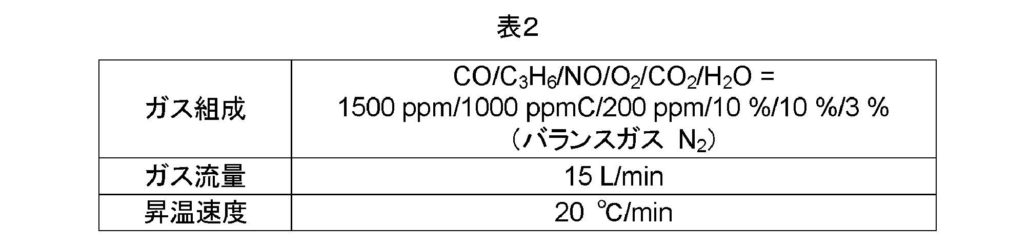
一般的なin situX線吸収微細構造解析(X-ray Absorption Fine Structure:XAFS)法に基づいて各サンプルの触媒担体に担持されている貴金属(Pt及びPd)の電子状態(価数)を調べた。即ち、既設のX線吸収微細構造解析装置を用い、予め500℃での酸化雰囲気(10%O2/残部N2)中での酸化処理後に65℃まで降温し、白金及びパラジウムの各L3-edgeのスペクトルからWhite lineと呼ばれるd電子空孔に起因するピークの高さを測定した。かかるピーク強度が高いほど供試金属種の価数が大きくなることが知られている。なお、Normalized peak heightはL3-edgeの吸収高さを1として規格化した。結果をPtについては図11及び図12に示し、Pdについては図13及び図14に示す。
表1に示す酸化物粉末のうち、サンプル1-1、1-3、1-4及び1-5の各酸化物粉末の比表面積を、吸着ガスを窒素とする一般的なBET1点法(窒素吸着法)に基づいて測定した。結果を図17に示す。
このグラフ(図17)から明らかなように、酸化物換算でAl成分(Al2O3)が40質量%以上であるサンプル1-4、1-1及び1-3については、比表面積が110m2/gを上回った(具体的には140m2/g以上200m2/g未満)。他方、酸化物換算でAl成分(Al2O3)が40質量%未満であるサンプル1-5については、比表面積が110m2/gを下回っていた。
表1に示す酸化物粉末のうち、サンプル1-1、2-3及び2-4の各酸化物粉末の熱耐久処理後のXRDピーク強度(ITi/IZr)を調べた。即ち、各サンプルを電気炉内(炉内雰囲気は空気)に配置し、1000℃で3時間の加熱処理を行った。その後、室温まで冷却した各サンプルについてXRDパターンを測定し、ジルコニア(ZrO2)の2θ角が30度(±0.2度)におけるピーク強度(IZr)と、ルチル型チタニア(TiO2)の2θ角が27度(±0.2度)におけるピーク強度(ITi)との比(ITi/IZr)を求めた。結果を図18に示す。
このグラフ(図18)から明らかなように、酸化物換算でTi成分(TiO2)が15質量%以下であるサンプル2-3及び1-1についてはピーク強度(ITi/IZr)が0.02以下であり、TiO2のピークがXRDで実質的に検出されないレベルにあった。他方、酸化物換算でTi成分(TiO2)が20質量%であるサンプル2-4については、ピーク強度(ITi/IZr)が0.1を超えて0.15近くもあり、TiO2の粒成長が認められた。
本実施例では、担体(粉末状態のもの)として上記サンプル1-1、サンプル1-2、サンプル1-4、サンプル2-3の計4種を採用した(表1)。あわせて比較例としてアルミナ担体であるサンプル3-1を採用した(表1)。貴金属としてはPtとPdを採用した。貴金属を担体に担持させる方法と材料は、上述した試験例と同様であるので重複した説明はしない。また、炭化水素吸着材としてBEA型ゼオライト(Si/Al比=40)を採用した。また、本実施例では、図4に示すような二層構造の触媒コート層を形成した。
触媒コート層の上層部形成用スラリーは、Pt(0.67g/L)及びPd(0.33g/L)を担持した何れかのサンプル担体25g/Lと、BEA型ゼオライト60g/Lと、バインダーとして焼成後のAl2O3量が17.5gとなる硝酸アルミニウム水溶液、及び適量の純水を混合することにより調製した。
一方、触媒コート層の下層部形成用スラリーは、Pt(1.33g/L)及びPd(0.67g/L)を担持した何れかのサンプル担体80g/Lと、上記バインダーとして焼成後のAl2O3量が17.5gとなる硝酸アルミニウム水溶液、及び適量の純水を混合することにより調製した。
次いで、同様の手法により、上記上層部形成用スラリーを、上記基材上に形成された下層部の表面にウォッシュコートした。通風乾燥後、500℃で1時間焼成することにより、上層部を形成した。これにより、二層構造の触媒コート層を基材上に備える排ガス浄化用酸化触媒が得られた。なお、ここで得られた排ガス浄化用酸化触媒全体に含まれる材料組成比(質量%)は以下の表3のとおりである。

上記製造した計5種類の排ガス浄化用酸化触媒について、電気炉を用いて、空気中において750℃で37時間にわたって加熱することにより、熱耐久処理を施した。
上記熱耐久処理を施した排ガス浄化用酸化触媒について、2.2リットルのディーゼルエンジンから排ガスを供給し、排ガス中のCO酸化性能を評価した。即ち、上記ディーゼルエンジンを用いて、欧州排出ガス測定法が規定するサイクル(New European Driving Cycle:NEDC)モード(図15参照)を再現した。また、前処理として、5分間触媒床温度を600℃にすることにより粒子状物質(PM)の燃焼による再生処理を行った。そして「領域2~4」において排ガスの平均温度が150℃になるように回転数を調整し、「領域2~4」(平均温度150℃)におけるCO浄化率(%)を算出した。
図16に示す結果から明らかなように、ここで開示される内容のAZT酸化物を担体とする排ガス浄化用酸化触媒(計4種のサンプル)は、熱耐久処理後にかかわらず、低温域の排ガス中のCOを効果的に酸化する高い触媒活性を保持する。
2 燃焼室
12 排気通路(排気管)
15 燃料供給弁
24 燃料タンク
30 ECU
40 排ガス浄化部
50 排ガス浄化用酸化触媒(DOC)
52 ハニカム基材
54 リブ壁(隔壁)
56 セル(貫通孔)
60 基材
62 触媒コート層
63,65 担体
64 下層部
66 上層部
68 炭化水素吸着材
70 貴金属粒子(酸化触媒金属)
72 白金(Pt)粒子
74 パラジウム(Pd)粒子
80 パティキュレートフィルタ(DPF)
100 排ガス浄化装置
Claims (11)
- 排ガス浄化用酸化触媒であって、
担体と、
該担体に担持される一酸化炭素の酸化を触媒する貴金属と、
を有しており、
ここで前記担体は、構成金属元素としてAlとZr或いはAlとZrとTiを、酸化物換算で以下の質量割合:
Al2O3 40~99質量%;
ZrO2 1~45質量%;
TiO2 0~15質量%;
で含む複合金属酸化物を主体に構成されている、排ガス浄化用酸化触媒。 - 基材と、該基材上に形成された触媒コート層とを備え、
前記触媒コート層は、前記複合金属酸化物を主体に構成された担体と該担体に担持される前記貴金属とを有している、請求項1に記載の排ガス浄化用酸化触媒。 - 前記複合金属酸化物は、AlとZr或いはAlとZrとTiを、酸化物換算で以下の質量割合:
Al2O3 50~90質量%;
ZrO2 5~40質量%;
TiO2 0~15質量%;
で含む、請求項1又は2に記載の排ガス浄化用酸化触媒。 - 前記貴金属としてパラジウム粒子を備える、請求項1~3の何れか一項に記載の排ガス浄化用酸化触媒。
- 前記パラジウム粒子のCOパルス吸着法に基づく平均粒子径が5nm以下である、請求項4に記載の排ガス浄化用酸化触媒。
- さらに炭化水素吸着材を備えている、請求項1~5の何れか一項に記載の排ガス浄化用酸化触媒。
- 前記炭化水素吸着材としてゼオライト粒子を備えている、請求項6に記載の排ガス浄化用酸化触媒。
- 前記担体のBET1点法による初期比表面積が110m2/g以上である、請求項1~7の何れか一項に記載の排ガス浄化用酸化触媒。
- 前記担体は、構成金属元素としてTiを含む前記複合金属酸化物を主体に構成されており、空気中で1000℃、3時間の熱耐久処理を行った後にもTiO2のピークがX線回折(XRD)で実質的に検出されない、請求項1~8の何れか一項に記載の排ガス浄化用酸化触媒。
- ディーゼルエンジンの排ガスを浄化するために用いられる、請求項1~9の何れか一項に記載の排ガス浄化用酸化触媒。
- エンジンから排出される排ガスを浄化する排ガス浄化装置であって、
前記エンジンに連通する排気通路と、該排気通路内に配置された排ガス浄化部とを備えており、
前記排ガス浄化部は、請求項1~10の何れか一項に記載の排ガス浄化用酸化触媒を備える、排ガス浄化装置。
Priority Applications (6)
| Application Number | Priority Date | Filing Date | Title |
|---|---|---|---|
| KR1020137027817A KR101573128B1 (ko) | 2011-04-08 | 2012-04-06 | 배기 가스 정화용 산화 촉매 |
| BR112013022321A BR112013022321A2 (pt) | 2011-04-08 | 2012-04-06 | catalisador de oxidação para purificação de gás exaurido |
| EP12767859.7A EP2695674A4 (en) | 2011-04-08 | 2012-04-06 | OXIDATION CATALYST FOR THE PURIFICATION OF EXHAUST GASES |
| JP2013508949A JPWO2012137930A1 (ja) | 2011-04-08 | 2012-04-06 | 排ガス浄化用酸化触媒 |
| AU2012240909A AU2012240909B2 (en) | 2011-04-08 | 2012-04-06 | Oxidation Catalyst for Exhaust Gas Purification |
| US14/110,314 US20140030158A1 (en) | 2011-04-08 | 2012-04-06 | Exhaust gas purification oxidation catalyst |
Applications Claiming Priority (2)
| Application Number | Priority Date | Filing Date | Title |
|---|---|---|---|
| JP2011-086219 | 2011-04-08 | ||
| JP2011086219 | 2011-04-08 |
Publications (1)
| Publication Number | Publication Date |
|---|---|
| WO2012137930A1 true WO2012137930A1 (ja) | 2012-10-11 |
Family
ID=46969318
Family Applications (1)
| Application Number | Title | Priority Date | Filing Date |
|---|---|---|---|
| PCT/JP2012/059546 WO2012137930A1 (ja) | 2011-04-08 | 2012-04-06 | 排ガス浄化用酸化触媒 |
Country Status (7)
| Country | Link |
|---|---|
| US (1) | US20140030158A1 (ja) |
| EP (1) | EP2695674A4 (ja) |
| JP (1) | JPWO2012137930A1 (ja) |
| KR (1) | KR101573128B1 (ja) |
| AU (1) | AU2012240909B2 (ja) |
| BR (1) | BR112013022321A2 (ja) |
| WO (1) | WO2012137930A1 (ja) |
Cited By (6)
| Publication number | Priority date | Publication date | Assignee | Title |
|---|---|---|---|---|
| WO2014129634A1 (ja) | 2013-02-25 | 2014-08-28 | ユミコア日本触媒株式会社 | 排ガス浄化用触媒およびそれを用いた排ガス浄化方法 |
| WO2018015259A1 (de) | 2016-07-19 | 2018-01-25 | Umicore Ag & Co. Kg | Dieseloxidationskatalysator |
| WO2018088201A1 (ja) | 2016-11-11 | 2018-05-17 | エヌ・イーケムキャット株式会社 | 排ガス浄化用三元触媒及びその製造方法、並びに排ガス浄化用触媒コンバータ |
| EP3815780A1 (en) | 2019-10-30 | 2021-05-05 | Umicore Ag & Co. Kg | Diesel oxidation catalyst |
| EP3865209A1 (en) | 2020-02-17 | 2021-08-18 | UMICORE AG & Co. KG | Diesel oxidation catalyst |
| US11484864B2 (en) | 2018-02-27 | 2022-11-01 | N.E. Chemcat Corporation | Exhaust gas-purifying three-way catalyst and method for producing same, and integral structure type exhaust gas-purifying catalyst |
Families Citing this family (7)
| Publication number | Priority date | Publication date | Assignee | Title |
|---|---|---|---|---|
| US9616386B2 (en) | 2015-03-23 | 2017-04-11 | Kabushiki Kaisha Toyota Chuo Kenkyusho | Catalyst for purification of exhaust gas, NOx storage-reduction catalyst, and method for purifying exhaust gas |
| KR101865744B1 (ko) * | 2016-11-17 | 2018-06-08 | 현대자동차 주식회사 | 배기가스 정화장치 |
| JP2019058876A (ja) | 2017-09-27 | 2019-04-18 | イビデン株式会社 | ハニカム触媒 |
| JP6698602B2 (ja) * | 2017-09-27 | 2020-05-27 | イビデン株式会社 | 排ガス浄化用ハニカム触媒 |
| JP2019058875A (ja) * | 2017-09-27 | 2019-04-18 | イビデン株式会社 | ハニカム触媒 |
| JP6684257B2 (ja) * | 2017-09-27 | 2020-04-22 | イビデン株式会社 | 排ガス浄化用ハニカム触媒 |
| KR102310675B1 (ko) * | 2018-08-20 | 2021-10-12 | (주)엘엑스하우시스 | 배기가스 정화용 촉매 |
Citations (11)
| Publication number | Priority date | Publication date | Assignee | Title |
|---|---|---|---|---|
| JPH09926A (ja) * | 1995-06-22 | 1997-01-07 | Toyota Central Res & Dev Lab Inc | 排ガス浄化用触媒 |
| JPH10118454A (ja) | 1996-10-23 | 1998-05-12 | Hino Motors Ltd | 排気ガス浄化装置 |
| JPH11169669A (ja) * | 1997-12-15 | 1999-06-29 | Petroleum Energy Center Found | 排ガス浄化方法 |
| JP2002282688A (ja) | 2001-01-16 | 2002-10-02 | Toyota Central Res & Dev Lab Inc | 触媒担体及びその製造方法と触媒及び排ガス浄化方法 |
| JP2003175318A (ja) * | 2002-10-24 | 2003-06-24 | Ngk Insulators Ltd | 排ガス浄化システム及び排ガス浄化方法 |
| JP2004160435A (ja) * | 2002-09-18 | 2004-06-10 | Nissan Motor Co Ltd | Co除去触媒 |
| JP2005067917A (ja) | 2003-08-28 | 2005-03-17 | Mitsubishi Heavy Ind Ltd | Co除去触媒装置及びco選択除去方法 |
| JP2005538300A (ja) * | 2002-09-13 | 2005-12-15 | ジョンソン、マッセイ、パブリック、リミテッド、カンパニー | 圧縮着火機関およびそのための排気機構 |
| JP2006043637A (ja) | 2004-08-06 | 2006-02-16 | Toyota Motor Corp | 排ガス浄化用触媒 |
| WO2007111004A1 (ja) * | 2006-03-28 | 2007-10-04 | Kabushiki Kaisha Toyota Chuo Kenkyusho | 排ガス浄化用触媒、その再生方法、それを用いた排ガス浄化装置及び排ガス浄化方法 |
| JP2009119430A (ja) * | 2007-11-19 | 2009-06-04 | Toyota Central R&D Labs Inc | 低温酸化触媒、その製造方法、および低温酸化触媒を用いた排ガスの浄化方法 |
Family Cites Families (7)
| Publication number | Priority date | Publication date | Assignee | Title |
|---|---|---|---|---|
| JP4098835B2 (ja) * | 1993-12-07 | 2008-06-11 | トヨタ自動車株式会社 | 排気ガス浄化用触媒 |
| JP3643948B2 (ja) * | 1999-03-15 | 2005-04-27 | 株式会社豊田中央研究所 | チタニア−ジルコニア系粉末およびその製造方法 |
| JP3858625B2 (ja) * | 2000-07-27 | 2006-12-20 | 株式会社豊田中央研究所 | 複合酸化物とその製造方法及び排ガス浄化用触媒とその製造方法 |
| JP4171977B2 (ja) * | 2003-04-21 | 2008-10-29 | 株式会社豊田中央研究所 | 触媒担体及びその製造方法と触媒及び排ガス浄化方法 |
| JP2010264376A (ja) * | 2009-05-14 | 2010-11-25 | Isuzu Motors Ltd | 吸・排気系部品の汚染防止触媒皮膜 |
| JP5534249B2 (ja) * | 2009-09-11 | 2014-06-25 | 株式会社豊田中央研究所 | 複合金属酸化物多孔体、それを用いた触媒、およびそれらの製造方法 |
| WO2011067863A1 (ja) * | 2009-12-01 | 2011-06-09 | トヨタ自動車株式会社 | 内燃機関の排気浄化装置 |
-
2012
- 2012-04-06 EP EP12767859.7A patent/EP2695674A4/en not_active Withdrawn
- 2012-04-06 WO PCT/JP2012/059546 patent/WO2012137930A1/ja active Application Filing
- 2012-04-06 AU AU2012240909A patent/AU2012240909B2/en not_active Ceased
- 2012-04-06 KR KR1020137027817A patent/KR101573128B1/ko active IP Right Grant
- 2012-04-06 BR BR112013022321A patent/BR112013022321A2/pt not_active IP Right Cessation
- 2012-04-06 JP JP2013508949A patent/JPWO2012137930A1/ja active Pending
- 2012-04-06 US US14/110,314 patent/US20140030158A1/en not_active Abandoned
Patent Citations (11)
| Publication number | Priority date | Publication date | Assignee | Title |
|---|---|---|---|---|
| JPH09926A (ja) * | 1995-06-22 | 1997-01-07 | Toyota Central Res & Dev Lab Inc | 排ガス浄化用触媒 |
| JPH10118454A (ja) | 1996-10-23 | 1998-05-12 | Hino Motors Ltd | 排気ガス浄化装置 |
| JPH11169669A (ja) * | 1997-12-15 | 1999-06-29 | Petroleum Energy Center Found | 排ガス浄化方法 |
| JP2002282688A (ja) | 2001-01-16 | 2002-10-02 | Toyota Central Res & Dev Lab Inc | 触媒担体及びその製造方法と触媒及び排ガス浄化方法 |
| JP2005538300A (ja) * | 2002-09-13 | 2005-12-15 | ジョンソン、マッセイ、パブリック、リミテッド、カンパニー | 圧縮着火機関およびそのための排気機構 |
| JP2004160435A (ja) * | 2002-09-18 | 2004-06-10 | Nissan Motor Co Ltd | Co除去触媒 |
| JP2003175318A (ja) * | 2002-10-24 | 2003-06-24 | Ngk Insulators Ltd | 排ガス浄化システム及び排ガス浄化方法 |
| JP2005067917A (ja) | 2003-08-28 | 2005-03-17 | Mitsubishi Heavy Ind Ltd | Co除去触媒装置及びco選択除去方法 |
| JP2006043637A (ja) | 2004-08-06 | 2006-02-16 | Toyota Motor Corp | 排ガス浄化用触媒 |
| WO2007111004A1 (ja) * | 2006-03-28 | 2007-10-04 | Kabushiki Kaisha Toyota Chuo Kenkyusho | 排ガス浄化用触媒、その再生方法、それを用いた排ガス浄化装置及び排ガス浄化方法 |
| JP2009119430A (ja) * | 2007-11-19 | 2009-06-04 | Toyota Central R&D Labs Inc | 低温酸化触媒、その製造方法、および低温酸化触媒を用いた排ガスの浄化方法 |
Non-Patent Citations (1)
| Title |
|---|
| See also references of EP2695674A4 |
Cited By (13)
| Publication number | Priority date | Publication date | Assignee | Title |
|---|---|---|---|---|
| US9421528B2 (en) | 2013-02-25 | 2016-08-23 | Umicore Shokubai Japan Co., Ltd. | Exhaust gas purifying catalyst and exhaust gas purification method using same |
| WO2014129634A1 (ja) | 2013-02-25 | 2014-08-28 | ユミコア日本触媒株式会社 | 排ガス浄化用触媒およびそれを用いた排ガス浄化方法 |
| JP6993355B2 (ja) | 2016-07-19 | 2022-01-13 | ユミコア・アクチエンゲゼルシャフト・ウント・コムパニー・コマンディットゲゼルシャフト | ディーゼル酸化触媒コンバータ |
| WO2018015259A1 (de) | 2016-07-19 | 2018-01-25 | Umicore Ag & Co. Kg | Dieseloxidationskatalysator |
| JP2019528155A (ja) * | 2016-07-19 | 2019-10-10 | ユミコア・アクチエンゲゼルシャフト・ウント・コムパニー・コマンディットゲゼルシャフトUmicore AG & Co.KG | ディーゼル酸化触媒コンバータ |
| US11052378B2 (en) | 2016-07-19 | 2021-07-06 | Umicore Ag & Co. Kg | Diesel oxidizing catalytic converter |
| WO2018088201A1 (ja) | 2016-11-11 | 2018-05-17 | エヌ・イーケムキャット株式会社 | 排ガス浄化用三元触媒及びその製造方法、並びに排ガス浄化用触媒コンバータ |
| US10857520B2 (en) | 2016-11-11 | 2020-12-08 | N.E. Chemcat Corporation | Exhaust gas-purifying three-way catalyst and method for producing the same, and exhaust gas-purifying catalytic converter |
| US11484864B2 (en) | 2018-02-27 | 2022-11-01 | N.E. Chemcat Corporation | Exhaust gas-purifying three-way catalyst and method for producing same, and integral structure type exhaust gas-purifying catalyst |
| EP3815780A1 (en) | 2019-10-30 | 2021-05-05 | Umicore Ag & Co. Kg | Diesel oxidation catalyst |
| WO2021084054A1 (en) | 2019-10-30 | 2021-05-06 | Umicore Ag & Co. Kg | Diesel oxidation catalyst |
| WO2021165280A1 (en) | 2020-02-17 | 2021-08-26 | Umicore Ag & Co. Kg | Diesel oxidation catalyst |
| EP3865209A1 (en) | 2020-02-17 | 2021-08-18 | UMICORE AG & Co. KG | Diesel oxidation catalyst |
Also Published As
| Publication number | Publication date |
|---|---|
| US20140030158A1 (en) | 2014-01-30 |
| AU2012240909A1 (en) | 2013-11-21 |
| AU2012240909B2 (en) | 2015-07-02 |
| BR112013022321A2 (pt) | 2019-09-24 |
| EP2695674A1 (en) | 2014-02-12 |
| JPWO2012137930A1 (ja) | 2014-07-28 |
| EP2695674A4 (en) | 2014-10-29 |
| KR20140002772A (ko) | 2014-01-08 |
| KR101573128B1 (ko) | 2015-11-30 |
Similar Documents
| Publication | Publication Date | Title |
|---|---|---|
| WO2012137930A1 (ja) | 排ガス浄化用酸化触媒 | |
| JP5664918B2 (ja) | 排ガス浄化用触媒 | |
| RU2504431C2 (ru) | УДЕРЖИВАЮЩИЕ NOx МАТЕРИАЛЫ И ЛОВУШКИ, УСТОЙЧИВЫЕ К ТЕРМИЧЕСКОМУ СТАРЕНИЮ | |
| JP5917516B2 (ja) | Nh3−形成活性が改良された、ガソリンリーンバーンエンジンのための触媒 | |
| JPWO2007119658A1 (ja) | 排ガス浄化触媒及びその製造方法 | |
| US20220055021A1 (en) | Layered three-way conversion (twc) catalyst and method of manufacuring the catalyst | |
| JP2006263581A (ja) | 排気ガス浄化用触媒 | |
| CN112916037A (zh) | 包含具有特定粒度分布的金属氧化物载体粒子的催化剂组合物 | |
| US20200347763A1 (en) | Niobium oxide doped materials as rhodium supports for three-way catalyst application | |
| KR20210041551A (ko) | 연료 차단 NOx 제어용 TWC 시스템 | |
| WO2020195777A1 (ja) | 排ガス浄化用触媒 | |
| KR20220002926A (ko) | 금속 산화물 나노입자 기반 촉매 및 이의 제조 및 사용 방법 | |
| JP5488215B2 (ja) | 排気ガス浄化用触媒 | |
| JP2021000588A (ja) | メタン浄化用触媒材料 | |
| JP6263991B2 (ja) | 触媒材の製造方法、並びにそれを用いた触媒付パティキュレートフィルタの製造方法及びガソリンエンジン用三元触媒の製造方法。 | |
| WO2020203838A1 (ja) | 触媒材料 | |
| CN113260454B (zh) | 层状三元转化(twc)催化剂和制造所述催化剂的方法 | |
| WO2024008078A9 (en) | Catalytic article for engine exhaust gas treatment | |
| US20230330653A1 (en) | Three-way conversion catalytic article | |
| JP4805031B2 (ja) | 排ガス浄化触媒、その製造方法及び使用方法 | |
| JP2012217933A (ja) | 排ガス浄化用触媒 | |
| CN117940212A (zh) | 包含铂、钯和铑的分区的三效转化催化剂 | |
| WO2015029320A1 (ja) | 排気ガス浄化用触媒及びその製造方法 |
Legal Events
| Date | Code | Title | Description |
|---|---|---|---|
| 121 | Ep: the epo has been informed by wipo that ep was designated in this application |
Ref document number: 12767859 Country of ref document: EP Kind code of ref document: A1 |
|
| ENP | Entry into the national phase |
Ref document number: 2013508949 Country of ref document: JP Kind code of ref document: A |
|
| WWE | Wipo information: entry into national phase |
Ref document number: 14110314 Country of ref document: US |
|
| NENP | Non-entry into the national phase |
Ref country code: DE |
|
| ENP | Entry into the national phase |
Ref document number: 20137027817 Country of ref document: KR Kind code of ref document: A |
|
| WWE | Wipo information: entry into national phase |
Ref document number: 2012767859 Country of ref document: EP |
|
| ENP | Entry into the national phase |
Ref document number: 2012240909 Country of ref document: AU Date of ref document: 20120406 Kind code of ref document: A |
|
| REG | Reference to national code |
Ref country code: BR Ref legal event code: B01A Ref document number: 112013022321 Country of ref document: BR |
|
| ENP | Entry into the national phase |
Ref document number: 112013022321 Country of ref document: BR Kind code of ref document: A2 Effective date: 20130830 |