WO2012137831A1 - アースボルト - Google Patents
アースボルト Download PDFInfo
- Publication number
- WO2012137831A1 WO2012137831A1 PCT/JP2012/059220 JP2012059220W WO2012137831A1 WO 2012137831 A1 WO2012137831 A1 WO 2012137831A1 JP 2012059220 W JP2012059220 W JP 2012059220W WO 2012137831 A1 WO2012137831 A1 WO 2012137831A1
- Authority
- WO
- WIPO (PCT)
- Prior art keywords
- screw
- protrusion
- insulating film
- bolt
- groove
- Prior art date
- Legal status (The legal status is an assumption and is not a legal conclusion. Google has not performed a legal analysis and makes no representation as to the accuracy of the status listed.)
- Ceased
Links
Images


Classifications
-
- F—MECHANICAL ENGINEERING; LIGHTING; HEATING; WEAPONS; BLASTING
- F16—ENGINEERING ELEMENTS AND UNITS; GENERAL MEASURES FOR PRODUCING AND MAINTAINING EFFECTIVE FUNCTIONING OF MACHINES OR INSTALLATIONS; THERMAL INSULATION IN GENERAL
- F16B—DEVICES FOR FASTENING OR SECURING CONSTRUCTIONAL ELEMENTS OR MACHINE PARTS TOGETHER, e.g. NAILS, BOLTS, CIRCLIPS, CLAMPS, CLIPS OR WEDGES; JOINTS OR JOINTING
- F16B33/00—Features common to bolt and nut
- F16B33/02—Shape of thread; Special thread-forms
-
- F—MECHANICAL ENGINEERING; LIGHTING; HEATING; WEAPONS; BLASTING
- F16—ENGINEERING ELEMENTS AND UNITS; GENERAL MEASURES FOR PRODUCING AND MAINTAINING EFFECTIVE FUNCTIONING OF MACHINES OR INSTALLATIONS; THERMAL INSULATION IN GENERAL
- F16B—DEVICES FOR FASTENING OR SECURING CONSTRUCTIONAL ELEMENTS OR MACHINE PARTS TOGETHER, e.g. NAILS, BOLTS, CIRCLIPS, CLAMPS, CLIPS OR WEDGES; JOINTS OR JOINTING
- F16B35/00—Screw-bolts; Stay-bolts; Screw-threaded studs; Screws; Set screws
- F16B35/007—Removing paint or dirt layers covering the threaded part of nut-like members
-
- F—MECHANICAL ENGINEERING; LIGHTING; HEATING; WEAPONS; BLASTING
- F16—ENGINEERING ELEMENTS AND UNITS; GENERAL MEASURES FOR PRODUCING AND MAINTAINING EFFECTIVE FUNCTIONING OF MACHINES OR INSTALLATIONS; THERMAL INSULATION IN GENERAL
- F16B—DEVICES FOR FASTENING OR SECURING CONSTRUCTIONAL ELEMENTS OR MACHINE PARTS TOGETHER, e.g. NAILS, BOLTS, CIRCLIPS, CLAMPS, CLIPS OR WEDGES; JOINTS OR JOINTING
- F16B35/00—Screw-bolts; Stay-bolts; Screw-threaded studs; Screws; Set screws
- F16B35/04—Screw-bolts; Stay-bolts; Screw-threaded studs; Screws; Set screws with specially-shaped head or shaft in order to fix the bolt on or in an object
- F16B35/06—Specially-shaped heads
-
- H—ELECTRICITY
- H01—ELECTRIC ELEMENTS
- H01R—ELECTRICALLY-CONDUCTIVE CONNECTIONS; STRUCTURAL ASSOCIATIONS OF A PLURALITY OF MUTUALLY-INSULATED ELECTRICAL CONNECTING ELEMENTS; COUPLING DEVICES; CURRENT COLLECTORS
- H01R11/00—Individual connecting elements providing two or more spaced connecting locations for conductive members which are, or may be, thereby interconnected, e.g. end pieces for wires or cables supported by the wire or cable and having means for facilitating electrical connection to some other wire, terminal, or conductive member, blocks of binding posts
- H01R11/11—End pieces or tapping pieces for wires, supported by the wire and for facilitating electrical connection to some other wire, terminal or conductive member
- H01R11/20—End pieces terminating in a needle point or analogous contact for penetrating insulation or cable strands
-
- H—ELECTRICITY
- H01—ELECTRIC ELEMENTS
- H01R—ELECTRICALLY-CONDUCTIVE CONNECTIONS; STRUCTURAL ASSOCIATIONS OF A PLURALITY OF MUTUALLY-INSULATED ELECTRICAL CONNECTING ELEMENTS; COUPLING DEVICES; CURRENT COLLECTORS
- H01R4/00—Electrically-conductive connections between two or more conductive members in direct contact, i.e. touching one another; Means for effecting or maintaining such contact; Electrically-conductive connections having two or more spaced connecting locations for conductors and using contact members penetrating insulation
- H01R4/28—Clamped connections, spring connections
- H01R4/30—Clamped connections, spring connections utilising a screw or nut clamping member
- H01R4/304—Clamped connections, spring connections utilising a screw or nut clamping member having means for improving contact
-
- H—ELECTRICITY
- H01—ELECTRIC ELEMENTS
- H01R—ELECTRICALLY-CONDUCTIVE CONNECTIONS; STRUCTURAL ASSOCIATIONS OF A PLURALITY OF MUTUALLY-INSULATED ELECTRICAL CONNECTING ELEMENTS; COUPLING DEVICES; CURRENT COLLECTORS
- H01R4/00—Electrically-conductive connections between two or more conductive members in direct contact, i.e. touching one another; Means for effecting or maintaining such contact; Electrically-conductive connections having two or more spaced connecting locations for conductors and using contact members penetrating insulation
- H01R4/28—Clamped connections, spring connections
- H01R4/30—Clamped connections, spring connections utilising a screw or nut clamping member
- H01R4/34—Conductive members located under head of screw
-
- F—MECHANICAL ENGINEERING; LIGHTING; HEATING; WEAPONS; BLASTING
- F16—ENGINEERING ELEMENTS AND UNITS; GENERAL MEASURES FOR PRODUCING AND MAINTAINING EFFECTIVE FUNCTIONING OF MACHINES OR INSTALLATIONS; THERMAL INSULATION IN GENERAL
- F16B—DEVICES FOR FASTENING OR SECURING CONSTRUCTIONAL ELEMENTS OR MACHINE PARTS TOGETHER, e.g. NAILS, BOLTS, CIRCLIPS, CLAMPS, CLIPS OR WEDGES; JOINTS OR JOINTING
- F16B2200/00—Constructional details of connections not covered for in other groups of this subclass
- F16B2200/93—Fastener comprising feature for establishing a good electrical connection, e.g. electrostatic discharge or insulation feature
Definitions
- the present invention relates to a ground bolt used for energizing at the same time as tightening when an electric device is attached to a housing of an automobile or the like.
- the conventional earth bolt described above has the following problems. It takes time to remove the paint and masking, and workability is poor. Since ground terminals, wiring, and plates are used, costs increase. In many cases, a plurality of fixing bolts are used, which is expensive.
- Patent Document 1 a pad portion as a ground electrode is provided and electrically connected by pressing, and in order to achieve water tightness, by providing a ridge portion separately from electrical connection, The intrusion was suppressed.
- the conventional earth bolts have the following problems when effective energization and water tightness are taken simultaneously with tightening.
- an object of the present invention is to solve the above-mentioned problems of the prior art, and at the same time as tightening, it is possible to ensure electrical conductivity and water tightness, and a grounding that can be held so as not to scatter the peeled paint pieces to the outside. Is to provide bolts.
- the earth bolt of the present application is an earth bolt used for electrical connection with a mating member on which an insulating film is formed, and has a screw portion and a head, A protrusion formed in an annular shape is provided on the outer side of the screw portion that protrudes from the seating surface of the head and can peel off the insulating film.
- the protruding portion protrudes from the seating surface, by rotating the protruding portion, it is possible to press and peel off the insulating film of the mating member to establish electrical continuity with the mating member.
- the protrusion is formed in an annular shape without a cut on the outer side of the screw part, the inner side of the protrusion can be made watertight from the outside.
- FIG. 2 is a partial cross-sectional view of the ground bolt shown in FIG. 1.
- action of the earth bolt shown in FIG. The figure which shows the earth bolt which concerns on the 2nd Embodiment of this invention.
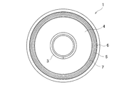
- FIG. 1 to 4 show a first embodiment of a ground bolt 1 according to the present invention.
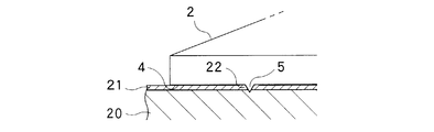
- the earth bolt 1 is used in electrical connection with a mating member 20 on which an insulating film 21 is formed, and has a head 2 and a screw portion 3.
- a protruding portion 5 that protrudes from the seat surface 4 of the portion 2 and is formed in an annular shape outside the screw portion 3 is provided.
- the mating member 20 is made of a metal material.
- the earth bolt 1 is also formed of a metal material.
- FIG. 3 shows the positional relationship between the ground bolt 1 and the mating member 20 having the insulating film 21 formed on the surface.
- the first groove 6 is formed in an annular shape adjacent to the outside of the protrusion 5 and recessed from the seating surface 4, and is annularly formed adjacent to the inside of the protrusion 5 and recessed from the seating surface 4.
- the second groove portion 7 is formed.
- the first groove 6 and the second groove 7 have a trapezoidal shape that spreads downward in a cross-sectional view.
- the protrusion 5 has a triangular shape, and the triangular shape has a first side 8 and a second side 9 sandwiching the apex.
- the first side 8 is on the outer side with respect to the axis of the screw part 3, and the second side 9 is on the inner side with respect to the axis of the screw part 3.
- the first side 8 forms a trapezoidal inner hypotenuse of the first groove 6, and the second side 9 forms a trapezoid outer hypotenuse of the second groove 7.
- the insulating film 22 from which the insulating film 21 has been peeled off by the protrusion 5 is guided by the first side 8 of the protrusion 5 and stored in the first groove 6, and the second side 9 of the protrusion 5 is It is guided and stored in the second groove portion 7.
- the protruding portion 5 protrudes from the seating surface 4, the insulating member 21 of the mating member 20 is pressed and peeled off by rotating the projecting portion 5 and the mating member. 20 and the projection 5 is formed in an annular shape without any cuts on the outside of the screw portion 3, so that the inside of the projection 5 can be made watertight from the outside. it can.
- the insulating film 22 peeled off by the protrusion portion 5 is stored in the first groove portion 6. It is possible to avoid leaving the separated insulating film pieces scattered.
- the second groove portion 7 which is adjacent to the inside of the protrusion portion 5 and is recessed from the seat surface 4 and is formed in an annular shape and which can receive the insulating film 22 peeled off by the protrusion portion 5 is further provided,
- the taken insulating film 22 can be securely stored on both the inside and outside of the protrusion 5.
- the protrusion 5 has a triangular shape
- the first side 8 sandwiching the top of the triangle forms a hypotenuse that forms the first groove 6, and the second side 9 sandwiching the top of the triangle is Since the oblique side forming the second groove portion 7 is formed, the insulating film 22 peeled off by the projection portion 5 is guided by the first side 8 and the second side 9, and the first groove portion 6 and the second groove portion 7 are surely connected. Can be stored.
- a protruding portion 5 that protrudes from the seating surface 4 of the head 2 and is formed in an annular shape outside the screw portion 3 without interruption.
- the first groove 6 shown in FIG. 3 is not formed adjacent to the protrusion 5.
- the insulating film 21 is very thin, the amount of the insulating film 22 that has been peeled off is small, so that even if it is left undisturbed, there is a case where no harm is caused. This is effective when the configuration is sufficient.
- the earth bolt 1 can be easily manufactured, and the projecting portion 5 can ensure electrical conductivity and water tightness simultaneously with tightening.
- the ground bolt 1 includes a protrusion 5 and a first groove 6, and unlike the case shown in FIG. 3, the second groove 7 is not provided.
- the ground bolt 1 can be manufactured relatively easily, and the projecting portion 5 can secure the electric conductivity and water tightness simultaneously with the tightening, and the first groove portion 6 The insulating film 22 thus peeled off can be stored and recovered.
- the ground bolt 1 includes a protrusion 5 and a first groove 6. Further, the outer seat surface 10 on the outer side with respect to the first groove portion 6 is formed higher toward the tip side of the screw portion 3 than the inner seat surface 11 on the inner side with respect to the first groove portion 6. A gap 12 is formed between the inner seat surface 11 and the insulating film 21 with the ground bolt 1 tightened.
- the outer seat surface 10 first contacts the insulating film 21 preferentially over the inner seat surface 11 outside the protrusion 5 and the first groove portion 6 and presses the insulating film 21 over a wide area of the outer seat surface 10. be able to. As a result, moisture from the outside of the ground bolt 1 can also be blocked by the outer seat surface 10, so that the water-tightness can be further ensured by the outer seat surface 10 in addition to ensuring the water-tightness by the protrusion 5. Can be secured.
- the ground bolt 1 includes an annular auxiliary protrusion 13 that protrudes from the seat surface 4 outside the protrusion 5.
- the auxiliary protrusion 13 has a protrusion height that is lower than the protrusion height of the protrusion 5.
- the insulating film 21 can be partially or wholly peeled off in the depth direction by the auxiliary protrusions 13 to ensure watertightness. By sufficiently peeling 21 in the depth direction, electrical conductivity and water tightness can be ensured, and water tightness can be ensured more reliably.
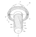
- FIGS. 9 and 10 in the ground bolt 15 according to the present embodiment, in addition to the ground bolt 1, the screw portion 3 protrudes outward in a radial direction at a part of the screw thread portion 16.
- a screw protrusion 17 is provided in the ground bolt 15 according to the present embodiment.
- a plurality of screw projections 17 are formed for each screw thread portion 16 of the screw portion 3, and the plurality of screw projections 17 are arranged in a spiral shape with respect to the axial direction of the screw portion 3.
- a plurality of screw projections 17 are formed at intervals in one screw thread portion 16, and as a result, as shown in FIGS. 9 and 10, they are arranged in a plurality of rows of spirals. .
- the screw protrusion 17 is formed by a raised portion 17b formed on both sides of the concave portion 17a by crushing the screw thread portion 16 of the screw portion 3 to form the concave portion 17a.
- the screw projection 17 can be formed simply by simply.
- FIG. 11 shows an enlarged view of the threaded portion 3 of the ground bolt 15.
- the screw portion 3 of the ground bolt 15 is shown together with a mating member on which a female screw is formed.
- Reference numeral 3a indicates the axis of the screw portion 3
- reference numeral 32 indicates the thread valley portion of the screw portion 3
- reference numeral 30 indicates the screw valley portion of the female screw of the mating member
- symbol 31 indicates the thread of the female screw of the mating member. Indicates the part.
- screw protrusions 17 (concave portions 17 a and raised portions 17 b) provided on the screw thread portions 16 connected to each other are schematically shown in the same manner.
- the screw projection 17 has a function of stripping off the second insulating film formed on the female screw of the nut 18 shown in FIG.
- FIG. 12 shows an example in which the ground bolt 15 according to the present embodiment is used.
- the thickness of the insulating film 21 and the size of the protrusion 5 are exaggeratedly large.
- an insulating film 21 and an insulating film 22 are formed on both surfaces of the counterpart member 20.
- An insulating film 24 and an insulating film 25 are formed on both side surfaces of the second mating member 23.
- the outer insulating film 24 is coated with the second mating member 23 from the outside after the nut 18 is welded and fixed to the second mating member 23 to ensure the conductivity between the second mating member 23 and the nut 18. Is formed.
- the insulating film 24 is formed by painting, the female screw portion inside the nut 18 is also painted to form an insulating film similar to the insulating film 24, and the screw portion 3 of the ground bolt 15 and the nut 18 The electrical conductivity during is impaired.
- the second insulating film formed by painting on the female screw portion of the nut 3 can be surely peeled off by the screw protrusions 17 arranged spirally with respect to the axial direction of the screw portion 3. become.
- the projecting portion 5 of the ground bolt 15 provides the electrical conductivity between the projecting portion 5 and the mating member 20, and the watertightness between the external environment of the insulating film 21 and the ground bolt 15.
- the electrical conductivity between the ground bolt 15 and the nut 18 can be obtained.
- the earth bolt 15 since the earth bolt 15 according to the present embodiment has both the protruding portion 5 and the screw protruding portion 17, the necessary water tightness in the mating member 20, and between the mating member 20 and the second mating member 23. Can be ensured by the earth bolt 15 as a single unit.
- the first groove portion that is adjacent to the outside of the protrusion portion and is recessed from the seat surface and formed in an annular shape is provided.
- the taken insulating film can be stored in the first groove portion, and it can be avoided that the separated insulating film pieces are left scattered.
- the second groove portion is formed adjacent to the inside of the protruding portion and is recessed from the seating surface and is formed in an annular shape and can store the insulating film peeled off by the protruding portion, the protruding portion is peeled off.
- the formed insulating film can be securely stored on both the inside and outside of the protrusion.
- the outer seat surface on the outer side with respect to the first groove portion is formed higher toward the tip side of the screw portion than the inner seat surface on the inner side with respect to the first groove portion, the projecting portion In addition to ensuring water tightness, the outer seat can ensure water tightness more reliably.
- the protrusion has a triangular shape, and the first side sandwiching the top of the triangular shape forms a hypotenuse that forms the first groove portion. Therefore, the insulating film peeled off by the protrusion is formed. It can be guided by the first side sandwiching the triangular top and can be securely stored in the first groove.
- the protrusion has a triangular shape
- the first side sandwiching the top of the triangle forms a hypotenuse that forms the first groove
- the second side sandwiching the top of the triangle is Since the oblique side forming the second groove portion is formed, the insulating film peeled off by the projection portion is guided by the first side and the second side sandwiching the triangular top, and the first groove portion and the second groove portion Can be securely stored.
- the auxiliary protrusion having a protrusion height that is lower than the protrusion height of the protrusion is provided to protrude from the seating surface and formed in an annular shape outside the protrusion, the insulating film is deepened by the auxiliary protrusion. It is possible to ensure water tightness by peeling part or all in the vertical direction, and at the same time, it is possible to ensure conductivity and water tightness by sufficiently peeling the insulating film in the depth direction by the protrusions, Water tightness can be ensured more reliably.
- the screw portion includes a screw protrusion portion that protrudes outward in the radial direction from the screw thread portion and can peel off the second insulating film formed on the female screw portion of the counterpart nut.
- the second insulating film of the second mating member can be peeled off, and electrical conductivity with the mating nut can be taken.
- the ground bolt and the nut are connected via the projecting portion and the screw projecting portion.
- a plurality of the screw projections are formed for each screw thread portion of the screw portion, and the plurality of screw projections are arranged in a spiral shape with respect to the axial direction of the screw portion.
- the second insulating film formed on the female screw portion of the nut can be surely peeled off by the screw protrusion.
- the screw protrusion is formed by a raised portion formed on both sides of the recessed portion by crushing the threaded portion of the threaded portion, so that it is simple simply by crushing the threaded portion.
- a screw protrusion can be formed on the surface.
Landscapes
- Engineering & Computer Science (AREA)
- General Engineering & Computer Science (AREA)
- Mechanical Engineering (AREA)
- Connections By Means Of Piercing Elements, Nuts, Or Screws (AREA)
- Gasket Seals (AREA)
- Motor Or Generator Frames (AREA)
- Elimination Of Static Electricity (AREA)
- Connection Of Plates (AREA)
- Installation Of Indoor Wiring (AREA)
- Cable Accessories (AREA)
Priority Applications (6)
| Application Number | Priority Date | Filing Date | Title |
|---|---|---|---|
| US14/004,498 US8858142B2 (en) | 2011-04-05 | 2012-04-04 | Earth bolt |
| RU2013148765/12A RU2543598C1 (ru) | 2011-04-05 | 2012-04-04 | Заземляющий болт |
| EP12767304.4A EP2696084B1 (en) | 2011-04-05 | 2012-04-04 | Earth bolt |
| CN201280016687.7A CN103597222B (zh) | 2011-04-05 | 2012-04-04 | 接地螺栓 |
| ES12767304.4T ES2685806T3 (es) | 2011-04-05 | 2012-04-04 | Perno de puesta a tierra |
| BR112013025508-0A BR112013025508B1 (pt) | 2011-04-05 | 2012-04-04 | parafuso terra |
Applications Claiming Priority (2)
| Application Number | Priority Date | Filing Date | Title |
|---|---|---|---|
| JP2011083662A JP5653824B2 (ja) | 2011-04-05 | 2011-04-05 | アースボルト |
| JP2011-083662 | 2011-04-05 |
Publications (1)
| Publication Number | Publication Date |
|---|---|
| WO2012137831A1 true WO2012137831A1 (ja) | 2012-10-11 |
Family
ID=46969225
Family Applications (1)
| Application Number | Title | Priority Date | Filing Date |
|---|---|---|---|
| PCT/JP2012/059220 Ceased WO2012137831A1 (ja) | 2011-04-05 | 2012-04-04 | アースボルト |
Country Status (8)
| Country | Link |
|---|---|
| US (1) | US8858142B2 (enExample) |
| EP (1) | EP2696084B1 (enExample) |
| JP (1) | JP5653824B2 (enExample) |
| CN (1) | CN103597222B (enExample) |
| BR (1) | BR112013025508B1 (enExample) |
| ES (1) | ES2685806T3 (enExample) |
| RU (1) | RU2543598C1 (enExample) |
| WO (1) | WO2012137831A1 (enExample) |
Cited By (3)
| Publication number | Priority date | Publication date | Assignee | Title |
|---|---|---|---|---|
| WO2015049761A1 (ja) * | 2013-10-03 | 2015-04-09 | 株式会社青山製作所 | ボルト |
| JP2019002541A (ja) * | 2017-06-19 | 2019-01-10 | イワタボルト株式会社 | 固着ボルト |
| WO2025214676A1 (de) * | 2024-04-11 | 2025-10-16 | Baier & Michels Gmbh & Co. Kg | Verbindungselement mit räumabschnitt, rohteil zur herstellung dieses verbindungselements und schraubverbindung mit diesem verbindungselement |
Families Citing this family (37)
| Publication number | Priority date | Publication date | Assignee | Title |
|---|---|---|---|---|
| US9865938B2 (en) * | 2012-07-05 | 2018-01-09 | Ironridge, Inc. | Apparatus for electrically bonding a solar array |
| US10186791B2 (en) | 2012-07-05 | 2019-01-22 | Ironridge, Inc. | Assembly for clamping and grounding objects |
| JP2017501772A (ja) * | 2014-10-06 | 2017-01-19 | ライト メディカル テクノロジー インコーポレイテッドWright Medical Technology, Inc. | ヘッドレスネジ型圧迫固定具用トルクドライバー |
| US10594250B2 (en) | 2015-08-03 | 2020-03-17 | Unirac Inc. | Hybrid solar panel mounting assembly |
| CN105201987A (zh) * | 2015-11-11 | 2015-12-30 | 重庆青山工业有限责任公司 | 一种用于变速器上的防松密封螺栓结构 |
| CN106363253B (zh) * | 2016-08-30 | 2018-10-16 | 温州市长江标准件有限公司 | 一种导电螺栓的制造方法 |
| WO2019016844A1 (ja) * | 2017-07-18 | 2019-01-24 | 三菱電機株式会社 | 締結部材 |
| AU2017440984B2 (en) | 2017-12-06 | 2020-02-27 | Stryker European Operations Holdings Llc | Orthopedic locking screw |
| JP7110626B2 (ja) * | 2018-03-05 | 2022-08-02 | 株式会社Gsユアサ | 電気機器 |
| CN108506312B (zh) * | 2018-03-08 | 2020-06-30 | 浙江吉达金属有限公司 | 调节螺钉组件及其制造工艺 |
| DE102019200240A1 (de) * | 2019-01-10 | 2020-07-16 | Arnold Umformtechnik Gmbh & Co. Kg | Verbindungsmittel zur Herstellung einer elektrisch leitenden Verbindung, Verfahren und Anordnung |
| US11848636B2 (en) | 2019-06-04 | 2023-12-19 | Pegasus Solar, Inc. | Skip rail system |
| TWM589743U (zh) * | 2019-09-12 | 2020-01-21 | 陳韋志 | 加強密閉性一體成型之螺絲頭 |
| US11174892B2 (en) * | 2019-09-25 | 2021-11-16 | Wei-Chih Chen | Screw assembly having enhanced airtight effect |
| CN112867872B (zh) * | 2019-09-27 | 2022-10-25 | 东芝三菱电机产业系统株式会社 | 垫圈及紧固构造 |
| JP7049304B2 (ja) * | 2019-11-01 | 2022-04-06 | 陳韋志 | 密閉性を強化した一体成形のねじ部材 |
| US12292075B2 (en) * | 2019-11-25 | 2025-05-06 | Pegasus Solar Inc | Twist-lock solar module clamp |
| US11377840B2 (en) | 2019-11-26 | 2022-07-05 | Pegasus Solar Inc. | One-piece bonding splice for rails |
| CN110762100A (zh) * | 2019-11-28 | 2020-02-07 | 眉山中车紧固件科技有限公司 | 一种用于导电材料紧固连接的拉铆钉 |
| CN111237312A (zh) * | 2020-01-16 | 2020-06-05 | 芜湖强振汽车紧固件有限公司 | 一种自锁螺栓及其制作方法 |
| NL2025247B1 (en) * | 2020-03-31 | 2021-10-22 | Legrand France | A sheet metal part for use in a housing for accommodating devices such as electrical, electronic and optical devices |
| JP7305292B2 (ja) | 2020-04-08 | 2023-07-10 | 株式会社青山製作所 | ボルト |
| CN114076141A (zh) * | 2020-08-21 | 2022-02-22 | 宾科汽车紧固件(昆山)有限公司 | 拉铆螺母及其制造方法 |
| JP6894562B1 (ja) * | 2020-11-10 | 2021-06-30 | 尾張精機株式会社 | 雄ねじ部材及び雄ねじ部材の製造方法 |
| US11990862B2 (en) | 2021-02-18 | 2024-05-21 | Pegasus Solar Inc. | Rail accessory mount |
| CN112963433A (zh) * | 2021-02-26 | 2021-06-15 | 重庆长安汽车股份有限公司 | 一种车门锁安装螺栓 |
| US11840141B2 (en) * | 2021-05-03 | 2023-12-12 | Nissan North America, Inc. | Vehicle drive train assembly |
| JP7683879B2 (ja) * | 2021-07-08 | 2025-05-27 | 株式会社青山製作所 | 摩擦係数安定剤排出機能を備えた締結部材 |
| US12281750B2 (en) | 2022-01-14 | 2025-04-22 | Pegasus Solar Inc | Grip rail clamp |
| CN115681289A (zh) * | 2022-10-20 | 2023-02-03 | 一汽奔腾轿车有限公司 | 一种带接地功能的焊接螺栓及其安装方法 |
| WO2024102828A1 (en) * | 2022-11-09 | 2024-05-16 | Acument Intellectual Properties, Llc | Fastening system with sealing arrangement |
| US20240369091A1 (en) * | 2023-05-03 | 2024-11-07 | Acument Intellectual Properties, Llc | Fastening system with sealing arrangement |
| KR102532537B1 (ko) * | 2022-12-19 | 2023-05-15 | 태용엔지니어링(주) | 접지용 근각 볼트 |
| KR200497223Y1 (ko) * | 2023-04-05 | 2023-08-31 | 정진홍 | 근각볼트로 연결되는 접지 케이싱 |
| EP4549757A1 (en) * | 2023-10-31 | 2025-05-07 | Volvo Car Corporation | Connecting element for connecting at least two components of a vehicle |
| FR3157483A1 (fr) * | 2023-12-20 | 2025-06-27 | Valeo Eautomotive Germany Gmbh | Dispositif étanche de connexion électrique, convertisseur et motorisation utilisant un tel dispositif, goujon adapté à être utilisé dans un tel dispositif. |
| DE102024205010A1 (de) * | 2024-05-29 | 2025-12-04 | Leoni Bordnetz-Systeme Gmbh | Elektrische Kontaktanordnung, Kontaktbaugruppe sowie Verfahren zur Herstellung einer solchen Kontaktbaugruppe |
Citations (6)
| Publication number | Priority date | Publication date | Assignee | Title |
|---|---|---|---|---|
| JPH05284625A (ja) * | 1992-03-27 | 1993-10-29 | Kanafuji Denko Kk | 電路資材の導電路確保接続ボルト部材及びそれを用いた導電性接続構造 |
| JPH069176U (ja) * | 1992-07-06 | 1994-02-04 | 株式会社ケンウッド | 装飾ケースのネジ止め構造 |
| JPH07286613A (ja) * | 1994-04-18 | 1995-10-31 | Takigen Mfg Co Ltd | ボルト孔隠蔽用キャップ |
| JPH08334112A (ja) * | 1995-06-06 | 1996-12-17 | Kubota Corp | 当接面積調整ボルト |
| JPH10331831A (ja) * | 1997-05-27 | 1998-12-15 | Aoyama Seisakusho Co Ltd | 弛み止めボルト |
| JP2009246740A (ja) | 2008-03-31 | 2009-10-22 | Nissan Motor Co Ltd | 車両用アンテナユニットのグラウンド接続構造 |
Family Cites Families (21)
| Publication number | Priority date | Publication date | Assignee | Title |
|---|---|---|---|---|
| US1968516A (en) * | 1930-07-22 | 1934-07-31 | P W Dieter Inc | Bolt |
| US1969796A (en) * | 1932-04-08 | 1934-08-14 | Dardelet Threadlock Corp | Separable fastener and installation thereof |
| US2056688A (en) * | 1934-11-15 | 1936-10-06 | Lamson & Sessions Co | Weather-tight bolt |
| US2210455A (en) * | 1938-05-31 | 1940-08-06 | Illinois Tool Works | Lock nut |
| US3426642A (en) * | 1962-02-05 | 1969-02-11 | Res Eng & Mfg | Self-tapping screws with threadforming projections |
| US4223711A (en) * | 1978-07-03 | 1980-09-23 | Russell, Burdsall & Ward Corporation | Self-locking fastener |
| US4290469A (en) * | 1979-09-04 | 1981-09-22 | Kishu Neji Co., Ltd. | Self-locking nut-type or bolt-type fastening device |
| US4490083A (en) * | 1980-01-10 | 1984-12-25 | Russell, Burdsall, & Ward Corporation | Sealing capped nut and bolt therefor |
| US4310272A (en) * | 1980-01-18 | 1982-01-12 | Textron Inc. | Threaded fastener and structural joint attained therewith |
| US4518294A (en) * | 1982-03-18 | 1985-05-21 | Illinois Tool Works Inc. | Rotary fastener |
| US4875818A (en) * | 1983-11-30 | 1989-10-24 | Elco Industries, Inc. | Screw having a sealing washer |
| US4749319A (en) * | 1986-11-19 | 1988-06-07 | Illinois Tool Works Inc. | Anti-stripping sheet metal screw |
| US4749321A (en) * | 1987-04-24 | 1988-06-07 | Elco Industries, Inc. | Sealing fastener |
| CA2125357C (en) * | 1993-06-09 | 1999-01-12 | David James Roberts | Self-drilling screw |
| US5743691A (en) * | 1997-02-03 | 1998-04-28 | Textron Inc. | Clinch-type fastener member |
| GB2340908A (en) * | 1998-08-21 | 2000-03-01 | Textron Fastening Syst Ltd | Expandable screw-threaded fastener |
| US7306418B2 (en) * | 2004-09-27 | 2007-12-11 | General Motors Corporation | Deforming member and captive fastener retaining method |
| DE102004062391A1 (de) * | 2004-12-23 | 2006-07-13 | Profil-Verbindungstechnik Gmbh & Co. Kg | Ein durch Nieten an ein Blechteil anbringbares Element sowie Zusammenbauteil und Verfahren zur Erzeugung des Zusammenbauteils |
| DE202006008721U1 (de) * | 2006-06-01 | 2007-10-11 | Profil Verbindungstechnik Gmbh & Co. Kg | Nietmutter und Kombination einer Nietmutter mit einem Blechteil |
| US7462043B2 (en) * | 2006-12-15 | 2008-12-09 | Ge Fanuc Embedded Systems, Inc. | Electrical connector element |
| CN201425050Y (zh) * | 2009-05-19 | 2010-03-17 | 书元机械企业(昆山)有限公司 | 复合式密封螺丝 |
-
2011
- 2011-04-05 JP JP2011083662A patent/JP5653824B2/ja active Active
-
2012
- 2012-04-04 WO PCT/JP2012/059220 patent/WO2012137831A1/ja not_active Ceased
- 2012-04-04 RU RU2013148765/12A patent/RU2543598C1/ru active
- 2012-04-04 BR BR112013025508-0A patent/BR112013025508B1/pt active IP Right Grant
- 2012-04-04 CN CN201280016687.7A patent/CN103597222B/zh active Active
- 2012-04-04 US US14/004,498 patent/US8858142B2/en active Active
- 2012-04-04 ES ES12767304.4T patent/ES2685806T3/es active Active
- 2012-04-04 EP EP12767304.4A patent/EP2696084B1/en active Active
Patent Citations (6)
| Publication number | Priority date | Publication date | Assignee | Title |
|---|---|---|---|---|
| JPH05284625A (ja) * | 1992-03-27 | 1993-10-29 | Kanafuji Denko Kk | 電路資材の導電路確保接続ボルト部材及びそれを用いた導電性接続構造 |
| JPH069176U (ja) * | 1992-07-06 | 1994-02-04 | 株式会社ケンウッド | 装飾ケースのネジ止め構造 |
| JPH07286613A (ja) * | 1994-04-18 | 1995-10-31 | Takigen Mfg Co Ltd | ボルト孔隠蔽用キャップ |
| JPH08334112A (ja) * | 1995-06-06 | 1996-12-17 | Kubota Corp | 当接面積調整ボルト |
| JPH10331831A (ja) * | 1997-05-27 | 1998-12-15 | Aoyama Seisakusho Co Ltd | 弛み止めボルト |
| JP2009246740A (ja) | 2008-03-31 | 2009-10-22 | Nissan Motor Co Ltd | 車両用アンテナユニットのグラウンド接続構造 |
Cited By (4)
| Publication number | Priority date | Publication date | Assignee | Title |
|---|---|---|---|---|
| WO2015049761A1 (ja) * | 2013-10-03 | 2015-04-09 | 株式会社青山製作所 | ボルト |
| US9903405B2 (en) | 2013-10-03 | 2018-02-27 | Aoyama Seisakusho Co., Ltd. | Bolt |
| JP2019002541A (ja) * | 2017-06-19 | 2019-01-10 | イワタボルト株式会社 | 固着ボルト |
| WO2025214676A1 (de) * | 2024-04-11 | 2025-10-16 | Baier & Michels Gmbh & Co. Kg | Verbindungselement mit räumabschnitt, rohteil zur herstellung dieses verbindungselements und schraubverbindung mit diesem verbindungselement |
Also Published As
| Publication number | Publication date |
|---|---|
| US8858142B2 (en) | 2014-10-14 |
| CN103597222B (zh) | 2016-01-13 |
| EP2696084A1 (en) | 2014-02-12 |
| BR112013025508B1 (pt) | 2020-12-08 |
| JP2012219854A (ja) | 2012-11-12 |
| CN103597222A (zh) | 2014-02-19 |
| ES2685806T3 (es) | 2018-10-11 |
| JP5653824B2 (ja) | 2015-01-14 |
| EP2696084A4 (en) | 2014-09-10 |
| BR112013025508A2 (pt) | 2016-12-27 |
| RU2543598C1 (ru) | 2015-03-10 |
| US20140079510A1 (en) | 2014-03-20 |
| EP2696084B1 (en) | 2018-06-06 |
Similar Documents
| Publication | Publication Date | Title |
|---|---|---|
| JP5653824B2 (ja) | アースボルト | |
| US10411397B2 (en) | Connector seal device | |
| JP2015115308A (ja) | 電線接続用の端子および該端子の電線接続構造 | |
| WO1999040330A1 (en) | Earth nut | |
| JP2015103494A (ja) | アース端子 | |
| KR20180001280U (ko) | 접지용 볼트 너트 조립체 | |
| JP6112421B2 (ja) | アース接続構造 | |
| JP2005142472A (ja) | 電気機器収納箱における電線貫通部の防水構造 | |
| JP6000812B2 (ja) | シールド付き電線用のコネクター | |
| JP5872888B2 (ja) | ねじの緩み止め構造 | |
| JP2015176852A (ja) | アース接続構造 | |
| JP6101592B2 (ja) | 結線構造、接続部材、並びに、接続工法 | |
| JP6156265B2 (ja) | アース端子 | |
| JP2019091611A (ja) | 単芯線の接続構造 | |
| JP6654438B2 (ja) | 止水構造 | |
| KR101429669B1 (ko) | 조립식 커넥터 | |
| KR200405281Y1 (ko) | 방우형 전선 연결용 분기 커넥터 | |
| JP3187365U (ja) | 自転車の泥除けに用いられる留め金具 | |
| JP5389132B2 (ja) | 電線接続構造および電線分岐接続具 | |
| JP2016006733A (ja) | 組合せ端子金具 | |
| JP2009259641A (ja) | 接地金具 | |
| JP2016149278A (ja) | ワイヤーハーネス | |
| JP5812525B2 (ja) | コネクタ | |
| JP2016079622A (ja) | ソーラーパネル固定装置 | |
| JP2015088411A (ja) | アース端子 |
Legal Events
| Date | Code | Title | Description |
|---|---|---|---|
| 121 | Ep: the epo has been informed by wipo that ep was designated in this application |
Ref document number: 12767304 Country of ref document: EP Kind code of ref document: A1 |
|
| DPE1 | Request for preliminary examination filed after expiration of 19th month from priority date (pct application filed from 20040101) | ||
| WWE | Wipo information: entry into national phase |
Ref document number: IDW00201304588 Country of ref document: ID |
|
| NENP | Non-entry into the national phase |
Ref country code: DE |
|
| ENP | Entry into the national phase |
Ref document number: 2013148765 Country of ref document: RU Kind code of ref document: A |
|
| WWE | Wipo information: entry into national phase |
Ref document number: 14004498 Country of ref document: US |
|
| REG | Reference to national code |
Ref country code: BR Ref legal event code: B01A Ref document number: 112013025508 Country of ref document: BR |
|
| ENP | Entry into the national phase |
Ref document number: 112013025508 Country of ref document: BR Kind code of ref document: A2 Effective date: 20131002 |