WO2012137773A1 - 燃料電池セル - Google Patents
燃料電池セル Download PDFInfo
- Publication number
- WO2012137773A1 WO2012137773A1 PCT/JP2012/059068 JP2012059068W WO2012137773A1 WO 2012137773 A1 WO2012137773 A1 WO 2012137773A1 JP 2012059068 W JP2012059068 W JP 2012059068W WO 2012137773 A1 WO2012137773 A1 WO 2012137773A1
- Authority
- WO
- WIPO (PCT)
- Prior art keywords
- frame
- fuel cell
- protrusions
- containing gas
- flow path
- Prior art date
Links
Images


Classifications
-
- H—ELECTRICITY
- H01—ELECTRIC ELEMENTS
- H01M—PROCESSES OR MEANS, e.g. BATTERIES, FOR THE DIRECT CONVERSION OF CHEMICAL ENERGY INTO ELECTRICAL ENERGY
- H01M8/00—Fuel cells; Manufacture thereof
- H01M8/04—Auxiliary arrangements, e.g. for control of pressure or for circulation of fluids
- H01M8/04082—Arrangements for control of reactant parameters, e.g. pressure or concentration
- H01M8/04201—Reactant storage and supply, e.g. means for feeding, pipes
-
- H—ELECTRICITY
- H01—ELECTRIC ELEMENTS
- H01M—PROCESSES OR MEANS, e.g. BATTERIES, FOR THE DIRECT CONVERSION OF CHEMICAL ENERGY INTO ELECTRICAL ENERGY
- H01M8/00—Fuel cells; Manufacture thereof
- H01M8/02—Details
- H01M8/0202—Collectors; Separators, e.g. bipolar separators; Interconnectors
- H01M8/0258—Collectors; Separators, e.g. bipolar separators; Interconnectors characterised by the configuration of channels, e.g. by the flow field of the reactant or coolant
- H01M8/026—Collectors; Separators, e.g. bipolar separators; Interconnectors characterised by the configuration of channels, e.g. by the flow field of the reactant or coolant characterised by grooves, e.g. their pitch or depth
-
- H—ELECTRICITY
- H01—ELECTRIC ELEMENTS
- H01M—PROCESSES OR MEANS, e.g. BATTERIES, FOR THE DIRECT CONVERSION OF CHEMICAL ENERGY INTO ELECTRICAL ENERGY
- H01M8/00—Fuel cells; Manufacture thereof
- H01M8/02—Details
- H01M8/0271—Sealing or supporting means around electrodes, matrices or membranes
- H01M8/0273—Sealing or supporting means around electrodes, matrices or membranes with sealing or supporting means in the form of a frame
-
- H—ELECTRICITY
- H01—ELECTRIC ELEMENTS
- H01M—PROCESSES OR MEANS, e.g. BATTERIES, FOR THE DIRECT CONVERSION OF CHEMICAL ENERGY INTO ELECTRICAL ENERGY
- H01M8/00—Fuel cells; Manufacture thereof
- H01M8/10—Fuel cells with solid electrolytes
- H01M2008/1095—Fuel cells with polymeric electrolytes
-
- H—ELECTRICITY
- H01—ELECTRIC ELEMENTS
- H01M—PROCESSES OR MEANS, e.g. BATTERIES, FOR THE DIRECT CONVERSION OF CHEMICAL ENERGY INTO ELECTRICAL ENERGY
- H01M2250/00—Fuel cells for particular applications; Specific features of fuel cell system
- H01M2250/20—Fuel cells in motive systems, e.g. vehicle, ship, plane
-
- Y—GENERAL TAGGING OF NEW TECHNOLOGICAL DEVELOPMENTS; GENERAL TAGGING OF CROSS-SECTIONAL TECHNOLOGIES SPANNING OVER SEVERAL SECTIONS OF THE IPC; TECHNICAL SUBJECTS COVERED BY FORMER USPC CROSS-REFERENCE ART COLLECTIONS [XRACs] AND DIGESTS
- Y02—TECHNOLOGIES OR APPLICATIONS FOR MITIGATION OR ADAPTATION AGAINST CLIMATE CHANGE
- Y02E—REDUCTION OF GREENHOUSE GAS [GHG] EMISSIONS, RELATED TO ENERGY GENERATION, TRANSMISSION OR DISTRIBUTION
- Y02E60/00—Enabling technologies; Technologies with a potential or indirect contribution to GHG emissions mitigation
- Y02E60/30—Hydrogen technology
- Y02E60/50—Fuel cells
-
- Y—GENERAL TAGGING OF NEW TECHNOLOGICAL DEVELOPMENTS; GENERAL TAGGING OF CROSS-SECTIONAL TECHNOLOGIES SPANNING OVER SEVERAL SECTIONS OF THE IPC; TECHNICAL SUBJECTS COVERED BY FORMER USPC CROSS-REFERENCE ART COLLECTIONS [XRACs] AND DIGESTS
- Y02—TECHNOLOGIES OR APPLICATIONS FOR MITIGATION OR ADAPTATION AGAINST CLIMATE CHANGE
- Y02T—CLIMATE CHANGE MITIGATION TECHNOLOGIES RELATED TO TRANSPORTATION
- Y02T90/00—Enabling technologies or technologies with a potential or indirect contribution to GHG emissions mitigation
- Y02T90/40—Application of hydrogen technology to transportation, e.g. using fuel cells
Definitions
- the present invention relates to a polymer electrolyte fuel cell, for example.
- Patent Document 1 discloses “a separator for a fuel cell and a fuel cell including the same”.
- the fuel cell disclosed in Patent Document 1 includes a flow path defining member that defines a reactive gas flow path for supplying a reactive gas to the power generator by having a contact portion that protrudes and contacts the power generator.
- a part of the reaction gas flow path is provided with a protrusion protruding from the flow path defining member toward the power generator. And the protrusion distance of the said convex part is shortened compared with the protrusion distance of the said contact part.
- a pressure difference (hereinafter referred to as “differential pressure”) is generated between the cathode and the anode of the power generator due to fluctuations in the reaction gas pressure.
- differential pressure a pressure difference
- the protruding distance of the convex portion is shorter than the protruding distance of the contact portion, there still remains a possibility that the power generator is deformed by the differential pressure and the reaction gas flow path is blocked.
- an object of the present invention is to provide a fuel cell capable of improving fatigue resistance without reducing the flow cross-sectional area of the reaction gas even when the differential pressure is repeatedly generated.
- the present invention sandwiches a frame body in which a membrane electrode assembly is formed between a pair of separators, and disposes a plurality of protrusions on both sides of the frame body at a predetermined interval.
- a gas flow path for hydrogen-containing gas is formed on one side of the frame, and a gas flow path for oxygen-containing gas is formed on the other side of the frame.
- the protrusion on the one surface side of the frame body and the protrusion on the other surface side of the frame body are arranged asymmetrically around the frame body in the stacking direction of the fuel cells.
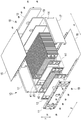
- FIG. 1 is a perspective view showing an appearance of a fuel cell stack using a fuel cell according to a first embodiment of the present invention. It is a perspective view which decomposes
- (A) is a partial sectional view showing a part of a fuel cell according to the third embodiment of the present invention
- (B) is a fuel cell according to the fourth embodiment of the present invention. It is a fragmentary sectional view showing a part of. It is a fragmentary sectional view showing a part of fuel cell concerning a fifth embodiment of the present invention. It is a fragmentary sectional view showing a part of fuel cell concerning a 6th embodiment of the present invention. It is a fragmentary sectional view showing a part of fuel cell concerning a 7th embodiment of the present invention.
- FIG. 1 is an external perspective view of a fuel cell stack using fuel cells according to the first embodiment of the present invention
- FIG. 2 is an exploded perspective view showing the fuel cell stack of FIG. 1 in an exploded manner
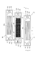
- 3 is an exploded perspective view showing the fuel battery cell according to the first embodiment of the present invention
- FIG. 4 is a front view of the fuel battery cell of FIG.
- the stacked current collecting plates 13 and 14 and the plurality of fuel cells A1 are clamped by a pair of end plates 11 and 12 from both sides (both ends in the stacking direction ⁇ ). .
- the current collector plates 13 and 14 and the plurality of fuel cells A1 are covered with fastening plates 15 and 16 and reinforcing plates 17 and 17 to constitute the fuel cell stack 10.
- Reference numeral 19 denotes a spacer.
- the end plates 11 and 12 the fastening plates 15 and 16 and the reinforcing plates 17 and 17 are fastened to each other by bolts 18 or the like, but the present invention is not limited to this.
- a frame body (hereinafter referred to as “frame”) 20 provided with a membrane electrode assembly 30 is sandwiched between a pair of separators 40 and 41.
- the power generation unit G is formed in a region facing the membrane electrode assembly 30.
- manifold units M and M for supplying and discharging hydrogen-containing gas or oxygen-containing gas are provided on both sides of the power generation unit G, and the power generation unit G is connected to each manifold unit M.
- Diffuser portions D and D which are flow regions for hydrogen-containing gas or oxygen-containing gas, are formed.
- the manifold portion M on one side (the left end portion shown in FIGS. 3 and 4) includes manifold holes H1 to H3. These manifold holes H1 to H3 are for oxygen-containing gas supply (H1), cooling fluid supply (H2) and hydrogen-containing gas supply (H3), and form respective flow paths along the stacking direction ⁇ . is doing.
- the manifold portion M on the other side (the right end portion shown in FIGS. 3 and 4) includes manifold holes H4 to H6.
- the manifold holes H4 to H6 are for hydrogen-containing gas discharge (H4), cooling fluid discharge (H5), and oxygen-containing gas discharge (H6), and form respective flow paths along the stacking direction ⁇ . is doing.
- the supply and discharge may be partially or entirely in a reverse positional relationship.
- the membrane electrode assembly 30 is also called MEA (Membrane Electrode Assembly), and has a structure in which, for example, an electrolyte membrane made of a solid polymer is sandwiched between an anode and a cathode (both not shown).
- MEA Membrane Electrode Assembly
- gas diffusion layers made of carbon paper, a porous body, and the like are laminated on the surfaces of the anode and the cathode, respectively.
- the membrane electrode assembly 30 performs power generation by an electrochemical reaction by supplying a hydrogen-containing gas to the anode and an oxygen-containing gas to the cathode.
- the membrane / electrode assembly 30 may be constituted by an electrolyte layer, an anode, and a cathode without providing the gas diffusion layer.
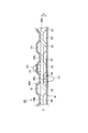
- FIG. 5 is a partial cross-sectional view showing the fuel cell A1 according to the first embodiment of the present invention as a cross section taken along line II shown in FIG.
- the arrow shown in FIG. 5 is a differential pressure
- (X) is the bending moment of the flame
- (Y) is hydrogen containing with respect to oxygen containing gas. It shows the bending moment of the frame 20 that occurs when the gas pressure is high.
- the frame electrode assembly 30 is integrally formed on the frame 20 by, for example, injection molding.
- the frame 20 is formed in a horizontally long rectangle in a front view as viewed from the stacking direction ⁇ of the fuel cells A1. Further, the frame 20 is formed with a substantially constant plate thickness, and the membrane electrode assembly 30 is disposed at the central portions of the upper, lower, left and right sides.
- the diffuser portion D is formed between each of the frame 20 and the separators 40, 41, that is, on the anode side and the cathode side (both sides) of the frame 20, respectively.
- a plurality of frustoconical protrusions 21 having the same shape and the same size are integrally formed on the frame 20 at a predetermined interval.
- the ratio of the height from the bottom surface (base portion) of the protrusion 21 to the upper bottom (upper portion) and the width dimension of the bottom surface can be set as appropriate.
- the projection 21 separates the frame 20 and the separators 40 and 41 facing the frame 20 in the ⁇ direction.
- a plurality of protrusions 21 are arranged on each diffuser portion D at a predetermined interval, thereby forming a hydrogen-containing gas flow path S1 and an oxygen-containing gas flow path S2.
- the hydrogen-containing gas flow path S1 and the oxygen-containing gas flow path S2 are simply referred to as “gas flow paths S1 and S2.”
- the projection 21 on the anode side (one surface side) of the frame 20 and the projection 21 on the cathode side (other surface side) of the frame 20 are the central axis C of the frame 20 in the stacking direction ⁇ of the fuel cells A1 ( They are arranged asymmetrically around the center of the frame 20 in the ⁇ direction. That is, the protrusions 21 are arranged so that the gas flow path S1 and the gas flow path S2 are asymmetric with respect to the frame 20 in the stacking direction ⁇ of the fuel cells A1.
- a cathode-side (other surface side) protrusion 21 is provided in the anode-side (one surface side) gas flow path S1, and a gas flow on the cathode side (other surface side).
- An anode-side (one surface-side) protrusion 21 is arranged to face the path S2.
- the protrusions 21 in the flow regions of the hydrogen-containing gas and the oxygen-containing gas are arranged so as not to face each other.
- the separators 40 and 41 are each formed by press-molding a metal plate such as stainless steel. As shown in FIGS. 3 and 4, the central portion facing the membrane electrode assembly 30 is formed in an uneven shape continuous in the ⁇ direction. Further, manifold holes H1 to H6 having the same shape and the same size as the manifold holes H1 to H6 of the frame 20 are formed on the left and right sides of the central portion so as to face each other.
- the separators 40 and 41 have the convex portions in contact with the membrane electrode assembly 30 in the concave and convex portions 40a and 41a facing the membrane electrode assembly 30, and the concave portions are made of hydrogen-containing gas (oxygen-containing gas). It is a flow path.
- the stress generation location and distribution of the frame 20 can be shifted even if a differential pressure occurs. Accordingly, the stress amplitude can be reduced, and the structural fatigue resistance can be increased without reducing the flow cross-sectional area of the reaction gas. Moreover, the plate
- FIG. 6 is a partial cross-sectional view showing a part of a fuel cell according to the second embodiment of the present invention in cross-section.
- the arrow shown in FIG. 6 is the differential pressure
- (X) is the bending moment generated in the frame 20A when the pressure of the oxygen-containing gas is higher than the hydrogen-containing gas
- (Y) is the pressure of the hydrogen-containing gas with respect to the oxygen-containing gas. This shows the bending moment of the frame 20A that occurs when the angle is high.
- the arrangement interval of the protrusions 21 is different from that of the fuel cell A1 according to the first embodiment.
- the arrangement interval of the protrusions 21 of the fuel cell A2 is made wider than the arrangement interval of the protrusions 21 of the fuel cell A1.
- the width dimension of the gas flow paths S1 and S2 is formed to be a dimension W1 wider than the arrangement interval of the protrusions 21 of the fuel cell A1.
- the distance between the base portion 21a of the projection 21 on the one surface side of the frame 20A and the corner portion 21b of the projection 21 on the other surface side is set to the dimension W2.
- the dimension W2 may be set in consideration of the bending moment generated.
- the frame 20A between the one-surface-side protrusion 21 and the other-surface-side protrusion 21 is provided. The generated stress can be suppressed.
- FIG. 7A is a partial sectional view showing a part of a fuel cell according to the third embodiment of the present invention in cross section
- FIG. 7B is a fuel according to the fourth embodiment of the present invention. It is a fragmentary sectional view which shows a part of battery cell in cross section.
- the arrow shown in FIG. 7 is the differential pressure
- (X) is the bending moment generated in the frame 20B when the pressure of the oxygen-containing gas is higher than the hydrogen-containing gas
- (Y) is the pressure of the hydrogen-containing gas with respect to the oxygen-containing gas. This shows the bending moment of the frame 20B that occurs when is high.
- the fuel battery cell A3 according to the third embodiment of the present invention shown in FIG. 7A has the above fuel in that protrusions 40b and 41b equivalent to the protrusion 21 are formed integrally with a pair of separators 40A and 41A. It is different from battery cells A1 and A2.
- the membrane electrode assembly 30 is formed integrally with the membrane electrode assembly 30 by, for example, injection molding.
- the fuel cell A3 is formed in a horizontally long rectangle in a front view as viewed from the stacking direction ⁇ , and has a substantially constant plate thickness.
- the membrane electrode assembly 30 is arranged at the center part of the upper, lower, left and right sides, but the projection is not arranged on the membrane electrode assembly 30.
- the separator 40A is integrally formed with a plurality of protrusions 40b in a region corresponding to the diffuser part D.
- the plurality of protrusions 40b have a truncated cone shape that is the same shape and the same size, and a plurality of protrusions 40b are arranged at a predetermined interval.
- the separator 41A is integrally formed with a plurality of protrusions 41b in a region corresponding to the diffuser part D.
- the protrusion 41b is a truncated cone having the same shape and the same size as the protrusion 40b, and a plurality of protrusions 41b are arranged at predetermined intervals.
- the anode-side (one surface side) protrusion 40b of the separator 40A and the cathode-side (other surface side) protrusion 41b of the separator 41A are asymmetric with respect to the frame 20B in the stacking direction ⁇ of the fuel cell A3. Is arranged. That is, the protrusions 40b and 41b are arranged so that the gas flow path S1 and the gas flow path S2 are asymmetrical about the frame 20B in the stacking direction ⁇ of the fuel cells A1.
- the cathode side (other surface side) protrusion 41b is formed on the anode (one surface side) gas flow path S1, and the cathode side (other surface side) gas flow path S2 is connected to the anode side (other surface side).
- the projections 40b on the one surface side are arranged to face each other.
- the stress generation location and distribution of the frame 20B can be shifted, so that the stress amplitude can be reduced. Further, the structural fatigue resistance can be increased without reducing the flow cross-sectional area of the reaction gas.
- FIG. 7B shows a fuel cell A4 according to a fourth embodiment of the present invention in which the arrangement intervals of the protrusions 40b and 41b are different from the fuel cell A3.
- the arrangement interval of the protrusions 40b and 41b of the fuel cell A4 is made wider than that of the fuel cell A3.
- the gas flow paths S1 and S2 of the fuel battery cell A4 are formed to have dimensions wider than the gas flow paths S1 and S2 of the fuel battery cell A3.
- the distance between the base portion of the projection 40b on the one surface side of the frame 20B and the corner portion of the projection 41b on the other surface side is set to the dimension W2.
- the dimension W2 may be set in consideration of the generated bending moment and the like, as in the fuel cell A2.
- the stress generation location and distribution of the frame 20B can be shifted, so that the stress amplitude can be reduced, and the structural cross section of the reaction gas can be reduced without decreasing.
- the fatigue resistance of can be increased.
- FIG. 8 is a partial cross-sectional view showing a part of a fuel battery cell according to the fifth embodiment of the present invention in cross-section.
- the arrows shown in FIG. 8 are the differential pressure, (X) is the bending moment generated in the frame 20C when the pressure of the oxygen-containing gas is higher than the hydrogen-containing gas, and (Y) is the pressure of the hydrogen-containing gas with respect to the oxygen-containing gas.
- the bending moment of the frame 20 ⁇ / b> C that occurs when the height is high is shown.
- symbol same as them is attached
- a fuel cell A5 according to a fifth embodiment of the present invention is similar to the separator 41 shown in FIG. 6 and the separator 40A shown in FIG. Is sandwiched between things.
- a power generation unit G (not shown in FIG. 8) was formed in a region facing the membrane electrode assembly 30.
- the frame 20C is formed integrally with the membrane electrode assembly 30 by, for example, injection molding.
- the fuel cell A5 is formed in a horizontally long rectangle in a front view as viewed from the stacking direction ⁇ and is formed to have a substantially constant plate thickness, and the membrane electrode assembly 30 is disposed in the central portion thereof. ing.
- This frame 20C is formed by arranging a plurality of conical trapezoidal projections 21 having the same shape and the same size on the cathode side of the diffuser portion D at a predetermined interval and making the anode side flat. .
- the anode-side (one surface side) protrusion 40b of the separator 40A and the cathode-side (other surface side) protrusion 21 of the frame 20C form the central axis C of the frame 20C in the stacking direction ⁇ of the fuel cells A5.
- the protrusions 40b and 21 are arranged so that the gas flow path S1 and the gas flow path S2 are asymmetrical about the frame 20C in the stacking direction ⁇ of the fuel cell A5.
- the protrusion 40b of the separator 40A is disposed at a position facing the gas flow path S2 formed by the protrusion 21 of the frame 20C and the separator 41.
- the stress generation location and distribution of the frame 20C can be shifted, so that the stress amplitude can be reduced. Further, the structural fatigue resistance can be increased without reducing the flow cross-sectional area of the reaction gas. In addition, it is possible to partially increase the plate thickness of the frame 20C to increase the section modulus of the stress generating portion.
- FIG. 9 is a partial cross-sectional view showing a part of a fuel battery cell according to the sixth embodiment of the present invention in cross-section.
- the arrows shown in FIG. 9 are differential pressures, (X) is the bending moment generated in the frame 20B when the pressure of the oxygen-containing gas is higher than the hydrogen-containing gas, and (Y) is the pressure of the hydrogen-containing gas with respect to the oxygen-containing gas. This shows the bending moment of the frame 20B that occurs when is high.
- symbol same as them is attached
- a fuel cell A6 according to the sixth embodiment of the present invention has a membrane electrode assembly 30 (not shown in FIG. 9) formed around the frame 20B shown in FIGS. 7 (A) and 7 (B). ) Is sandwiched between the separator 40B and the equivalent of the separator 41A shown in FIG. 7B.
- the separator 40B is integrally formed with a plurality of protrusions 40c in a region corresponding to the diffuser portion D.
- the protrusions 40c have a truncated cone shape having the same shape and the same size, and a plurality of protrusions 40c are arranged at a predetermined interval. Further, the area of the contact surface 40c ′ where the protrusion 40c contacts the frame 20B is increased as compared with the case of the protrusion 40b (41b).
- the protrusion 40c of the separator 40B and the protrusion 41b of the separator 41A are arranged to face each other.
- the projection 40c on the anode side (one surface side) of the separator 40B and the projection 41b on the cathode side (other surface side) of the separator 41A are asymmetric with respect to the frame 20B in the stacking direction ⁇ of the fuel cell A6.
- the protrusions 40c and 41b are arranged so that the gas flow path S1 and the gas flow path S2 are asymmetric with respect to the frame 20B in the stacking direction ⁇ of the fuel cell A6.
- the stress generation location and distribution of the frame 20B can be shifted, so that the stress amplitude can be reduced, and the structural cross section of the reaction gas can be reduced without decreasing.
- the fatigue resistance of can be increased.
- FIG. 10 is a partial cross-sectional view showing a part of a fuel cell according to the seventh embodiment of the present invention.
- the arrow indicates the differential pressure
- (X) indicates the bending moment generated in the frame 20D when the pressure of the oxygen-containing gas is higher than that of the hydrogen-containing gas
- (Y) indicates the pressure of the hydrogen-containing gas with respect to the oxygen-containing gas. This shows the bending moment of the frame 20D that occurs when is high.
- symbol same as them is attached
- a fuel cell A7 according to a seventh embodiment of the present invention includes a membrane electrode assembly 30 (not shown in FIG. 10) having a frame 20D formed between a pair of separators 40 and 41 shown in FIG. The structure is sandwiched between equivalents.
- the frame 20D is formed integrally with the membrane electrode assembly 30 by, for example, injection molding.
- the fuel cell A7 is formed in a horizontally long rectangle when viewed from the stacking direction ⁇ , and has a substantially constant thickness.
- the membrane electrode assembly 30 (not shown) is disposed in the center portion of the frame 20D.
- the frame 20D has a structure in which a plurality of protrusions 22 and 23 having different sizes are disposed on the anode side surface and the cathode side surface, respectively.
- the protrusions 22, 23 are formed in a truncated cone shape, and the area of the contact surface 22 a of the protrusion 22 with the separator 40 is larger than the area of the contact surface 23 a of the protrusion 23 with the separator 41. 22 and the protrusion 23 are arranged to face each other.
- the projection 22 on the anode side (one surface side) of the frame 20D and the projection 23 on the cathode side (other surface side) of the frame 20D form the central axis C of the frame 20D in the stacking direction ⁇ of the fuel cells A7.
- the interval between the bases of the protrusions 23 is set to the dimension L.
- the stress generation location and distribution of the frame 20D can be shifted. Accordingly, the stress amplitude can be reduced, and the structural fatigue resistance can be increased without reducing the flow cross-sectional area of the reaction gas.
- the frustoconical shape is exemplified as the protrusion, but a known shape such as a cylindrical shape, a prismatic shape, an elliptical prism shape, or the like can be adopted.
- the stress generation location and distribution of the frame can be shifted even if a differential pressure occurs, so that the structural fatigue resistance can be increased without reducing the flow cross-sectional area of the reaction gas.
Abstract
Description
21,22,23,40b,41b,40c 突起
30 膜電極接合体
40,41、40A,40B セパレータ
A1~A7 燃料電池セル
D 流通領域(ディフューザ部)
S1,S2 ガス流路
Claims (9)
- 膜電極接合体を有する枠体と、
該枠体を両面側から挟持する一対のセパレータと、
上記枠体の両面側に、互いに所定間隔をおいて配設された複数の突起と、
上記枠体の一面側に形成した水素含有ガスのガス流路と、
上記枠体の他面側に形成した酸素含有ガスのガス流路と、を備え、
上記枠体の一面側の突起と他面側の突起は、燃料電池セルの積層方向において枠体を中心にして非対称に配置されていることを特徴とする燃料電池セル。 - 上記水素含有ガスのガス流路と酸素含有ガスのガス流路とが燃料電池セルの積層方向において枠体を中心にして非対称形状となるように、上記突起を配設していることを特徴とする請求項1に記載の燃料電池セル。
- 上記複数の突起を枠体に一体的に形成していることを特徴とする請求項1又は2に記載の燃料電池セル。
- 上記一対のセパレータの少なくとも一方に、複数の突起を一体的に形成していることを特徴とする請求項1~3のいずれか1項に記載の燃料電池セル。
- 上記一対のセパレータの両方に、複数の突起を一体的に形成していることを特徴とする請求項1又は2に記載の燃料電池セル。
- 上記一方のセパレータの突起と他方のセパレータの突起が枠体に当接する面積が互いに相違することを特徴とする請求項5に記載の燃料電池セル。
- 上記一方のセパレータの突起と他方のセパレータの突起が互いに対向して配置されていることを特徴とする請求項6に記載の燃料電池セル。
- 上記枠体の両面に形成された突起がセパレータに当接する面積が互いに相違することを特徴とする請求項1~3のいずれか1項に記載の燃料電池セル。
- 上記枠体の両面に形成された突起が互いに対向して配置されていることを特徴とする請求項8に記載の燃料電池セル。
Priority Applications (4)
| Application Number | Priority Date | Filing Date | Title |
|---|---|---|---|
| US13/824,173 US10256486B2 (en) | 2011-04-05 | 2012-04-03 | Fuel cell |
| EP12767238.4A EP2696414B1 (en) | 2011-04-05 | 2012-04-03 | Fuel cell |
| CN201280002825.6A CN103098277B (zh) | 2011-04-05 | 2012-04-03 | 燃料电池单元 |
| CA2812907A CA2812907C (en) | 2011-04-05 | 2012-04-03 | Fuel cell having increased structural fatigue resistance |
Applications Claiming Priority (2)
| Application Number | Priority Date | Filing Date | Title |
|---|---|---|---|
| JP2011-083533 | 2011-04-05 | ||
| JP2011083533A JP5786419B2 (ja) | 2011-04-05 | 2011-04-05 | 燃料電池セル |
Publications (1)
| Publication Number | Publication Date |
|---|---|
| WO2012137773A1 true WO2012137773A1 (ja) | 2012-10-11 |
Family
ID=46969170
Family Applications (1)
| Application Number | Title | Priority Date | Filing Date |
|---|---|---|---|
| PCT/JP2012/059068 WO2012137773A1 (ja) | 2011-04-05 | 2012-04-03 | 燃料電池セル |
Country Status (6)
| Country | Link |
|---|---|
| US (1) | US10256486B2 (ja) |
| EP (1) | EP2696414B1 (ja) |
| JP (1) | JP5786419B2 (ja) |
| CN (1) | CN103098277B (ja) |
| CA (1) | CA2812907C (ja) |
| WO (1) | WO2012137773A1 (ja) |
Cited By (1)
| Publication number | Priority date | Publication date | Assignee | Title |
|---|---|---|---|---|
| EP2916376A1 (en) * | 2012-11-02 | 2015-09-09 | Toyota Jidosha Kabushiki Kaisha | Cell module and fuel cell stack |
Families Citing this family (4)
| Publication number | Priority date | Publication date | Assignee | Title |
|---|---|---|---|---|
| US10903508B2 (en) * | 2013-01-18 | 2021-01-26 | Daimler Ag | Fuel cell assemblies and preparation methods therfor |
| WO2017141490A1 (ja) * | 2016-02-15 | 2017-08-24 | 日産自動車株式会社 | 燃料電池の単セル構造 |
| JP6690503B2 (ja) * | 2016-11-09 | 2020-04-28 | トヨタ自動車株式会社 | 燃料電池単セル |
| CN111293325B (zh) * | 2020-04-28 | 2020-08-14 | 北京朔景新能源科技有限公司 | 燃料电池、以及用于燃料电池的双极板和双极板组件 |
Citations (9)
| Publication number | Priority date | Publication date | Assignee | Title |
|---|---|---|---|---|
| JP2001085034A (ja) * | 1999-09-10 | 2001-03-30 | Chubu Electric Power Co Inc | 平板型固体電解質燃料電池 |
| JP2006004677A (ja) * | 2004-06-15 | 2006-01-05 | Toshiba Fuel Cell Power Systems Corp | 燃料電池 |
| JP2006331944A (ja) * | 2005-05-27 | 2006-12-07 | Ngk Spark Plug Co Ltd | 固体酸化物燃料電池 |
| JP2007035296A (ja) * | 2005-07-22 | 2007-02-08 | Nissan Motor Co Ltd | 電解質膜/電極積層体および燃料電池セル |
| JP2008226682A (ja) * | 2007-03-14 | 2008-09-25 | Toyota Motor Corp | 燃料電池及びその製造方法、並びに、燃料電池スタック |
| JP2009104922A (ja) * | 2007-10-24 | 2009-05-14 | Toyota Motor Corp | 燃料電池および燃料電池の製造方法 |
| JP2009170206A (ja) * | 2008-01-15 | 2009-07-30 | Nissan Motor Co Ltd | 燃料電池及び燃料電池用セパレータ |
| JP2010205669A (ja) | 2009-03-05 | 2010-09-16 | Toyota Motor Corp | セパレータおよびそれを備えた燃料電池 |
| JP2011083533A (ja) | 2009-10-19 | 2011-04-28 | Yukiyo Yoshimura | 提げ手付きバッグ用カバーシート |
Family Cites Families (15)
| Publication number | Priority date | Publication date | Assignee | Title |
|---|---|---|---|---|
| US6261710B1 (en) * | 1998-11-25 | 2001-07-17 | Institute Of Gas Technology | Sheet metal bipolar plate design for polymer electrolyte membrane fuel cells |
| JP4312290B2 (ja) * | 1999-01-29 | 2009-08-12 | アイシン高丘株式会社 | 燃料電池及びセパレータ |
| US7153602B2 (en) * | 2000-05-08 | 2006-12-26 | Honda Giken Kogyo Kabushiki Kaisha | Fuel cell assembly |
| US7807312B2 (en) * | 2006-01-12 | 2010-10-05 | Ultracell Corporation | Portable electrical energy generation equipment |
| JP2007207707A (ja) * | 2006-02-06 | 2007-08-16 | Toyota Motor Corp | 燃料電池 |
| JP5026708B2 (ja) | 2006-02-09 | 2012-09-19 | 東海ゴム工業株式会社 | 固体高分子型燃料電池用セルおよびそれを用いた固体高分子型燃料電池 |
| JP5100640B2 (ja) | 2006-04-24 | 2012-12-19 | パナソニック株式会社 | Mea部材、及び高分子電解質形燃料電池 |
| JP2007305325A (ja) * | 2006-05-09 | 2007-11-22 | Toyota Motor Corp | 燃料電池 |
| JP4289398B2 (ja) * | 2007-01-10 | 2009-07-01 | トヨタ自動車株式会社 | シール一体型膜電極接合体 |
| JP5306615B2 (ja) | 2007-08-09 | 2013-10-02 | 本田技研工業株式会社 | 燃料電池 |
| KR100955740B1 (ko) | 2007-10-12 | 2010-04-30 | 파나소닉 주식회사 | 고분자 전해질형 연료 전지용의 전극-막-프레임 접합체 및 그 제조 방법, 및 고분자 전해질형 연료 전지 |
| CN101790811B (zh) | 2008-05-30 | 2013-09-25 | 松下电器产业株式会社 | Mea部件和固体高分子型燃料电池 |
| CN101572318B (zh) * | 2009-06-16 | 2010-12-08 | 新源动力股份有限公司 | 一种质子交换膜燃料电池金属双极板 |
| JP5485727B2 (ja) * | 2010-01-27 | 2014-05-07 | 本田技研工業株式会社 | 燃料電池スタック |
| US8999597B2 (en) | 2010-06-15 | 2015-04-07 | Nissan Motor Co., Ltd. | Fuel cell |
-
2011
- 2011-04-05 JP JP2011083533A patent/JP5786419B2/ja not_active Expired - Fee Related
-
2012
- 2012-04-03 CN CN201280002825.6A patent/CN103098277B/zh not_active Expired - Fee Related
- 2012-04-03 CA CA2812907A patent/CA2812907C/en not_active Expired - Fee Related
- 2012-04-03 EP EP12767238.4A patent/EP2696414B1/en not_active Not-in-force
- 2012-04-03 WO PCT/JP2012/059068 patent/WO2012137773A1/ja active Application Filing
- 2012-04-03 US US13/824,173 patent/US10256486B2/en not_active Expired - Fee Related
Patent Citations (9)
| Publication number | Priority date | Publication date | Assignee | Title |
|---|---|---|---|---|
| JP2001085034A (ja) * | 1999-09-10 | 2001-03-30 | Chubu Electric Power Co Inc | 平板型固体電解質燃料電池 |
| JP2006004677A (ja) * | 2004-06-15 | 2006-01-05 | Toshiba Fuel Cell Power Systems Corp | 燃料電池 |
| JP2006331944A (ja) * | 2005-05-27 | 2006-12-07 | Ngk Spark Plug Co Ltd | 固体酸化物燃料電池 |
| JP2007035296A (ja) * | 2005-07-22 | 2007-02-08 | Nissan Motor Co Ltd | 電解質膜/電極積層体および燃料電池セル |
| JP2008226682A (ja) * | 2007-03-14 | 2008-09-25 | Toyota Motor Corp | 燃料電池及びその製造方法、並びに、燃料電池スタック |
| JP2009104922A (ja) * | 2007-10-24 | 2009-05-14 | Toyota Motor Corp | 燃料電池および燃料電池の製造方法 |
| JP2009170206A (ja) * | 2008-01-15 | 2009-07-30 | Nissan Motor Co Ltd | 燃料電池及び燃料電池用セパレータ |
| JP2010205669A (ja) | 2009-03-05 | 2010-09-16 | Toyota Motor Corp | セパレータおよびそれを備えた燃料電池 |
| JP2011083533A (ja) | 2009-10-19 | 2011-04-28 | Yukiyo Yoshimura | 提げ手付きバッグ用カバーシート |
Cited By (3)
| Publication number | Priority date | Publication date | Assignee | Title |
|---|---|---|---|---|
| EP2916376A1 (en) * | 2012-11-02 | 2015-09-09 | Toyota Jidosha Kabushiki Kaisha | Cell module and fuel cell stack |
| EP2916376A4 (en) * | 2012-11-02 | 2016-02-17 | Toyota Motor Co Ltd | CELL MODULE AND FUEL CELL STACK |
| US9525188B2 (en) | 2012-11-02 | 2016-12-20 | Toyota Jidosha Kabushiki Kaisha | Cell module and fuel cell stack |
Also Published As
| Publication number | Publication date |
|---|---|
| US20130183606A1 (en) | 2013-07-18 |
| EP2696414A4 (en) | 2014-08-27 |
| CN103098277B (zh) | 2018-07-17 |
| US10256486B2 (en) | 2019-04-09 |
| CA2812907C (en) | 2017-01-10 |
| EP2696414B1 (en) | 2017-09-06 |
| JP5786419B2 (ja) | 2015-09-30 |
| JP2012221619A (ja) | 2012-11-12 |
| CA2812907A1 (en) | 2012-10-11 |
| CN103098277A (zh) | 2013-05-08 |
| EP2696414A1 (en) | 2014-02-12 |
Similar Documents
| Publication | Publication Date | Title |
|---|---|---|
| JP5445986B2 (ja) | 燃料電池セル | |
| JP5234446B2 (ja) | 燃料電池スタック用金属セパレータの積層性向上構造 | |
| US8790843B2 (en) | Fuel cell stack | |
| WO2012137773A1 (ja) | 燃料電池セル | |
| JP2009117220A (ja) | 燃料電池用セパレータおよび燃料電池 | |
| KR101963976B1 (ko) | 연료 전지의 단셀 | |
| US20160190610A1 (en) | Membrane electrode assembly with frame, fuel cell single cell, and fuel cell stack | |
| JP2015514280A (ja) | 燃料電池スタック | |
| JP4189345B2 (ja) | 燃料電池 | |
| KR102173663B1 (ko) | 연료 전지 셀 | |
| JP5741920B2 (ja) | 燃料電池セル | |
| EP3486986B1 (en) | Fuel cell stack | |
| JP5835991B2 (ja) | 燃料電池 | |
| WO2015133508A1 (ja) | セパレータ及びこれを備えた燃料電池 | |
| JP2020053266A (ja) | 燃料電池スタック | |
| JP2020047518A (ja) | 燃料電池 |
Legal Events
| Date | Code | Title | Description |
|---|---|---|---|
| WWE | Wipo information: entry into national phase |
Ref document number: 201280002825.6 Country of ref document: CN |
|
| 121 | Ep: the epo has been informed by wipo that ep was designated in this application |
Ref document number: 12767238 Country of ref document: EP Kind code of ref document: A1 |
|
| WWE | Wipo information: entry into national phase |
Ref document number: 13824173 Country of ref document: US |
|
| REEP | Request for entry into the european phase |
Ref document number: 2012767238 Country of ref document: EP |
|
| WWE | Wipo information: entry into national phase |
Ref document number: 2012767238 Country of ref document: EP |
|
| ENP | Entry into the national phase |
Ref document number: 2812907 Country of ref document: CA |
|
| NENP | Non-entry into the national phase |
Ref country code: DE |