EP2916376A1 - Cell module and fuel cell stack - Google Patents
Cell module and fuel cell stack Download PDFInfo
- Publication number
- EP2916376A1 EP2916376A1 EP13851983.0A EP13851983A EP2916376A1 EP 2916376 A1 EP2916376 A1 EP 2916376A1 EP 13851983 A EP13851983 A EP 13851983A EP 2916376 A1 EP2916376 A1 EP 2916376A1
- Authority
- EP
- European Patent Office
- Prior art keywords
- bonding
- separator
- area
- cell
- cell module
- Prior art date
- Legal status (The legal status is an assumption and is not a legal conclusion. Google has not performed a legal analysis and makes no representation as to the accuracy of the status listed.)
- Granted
Links
- 239000000446 fuel Substances 0.000 title claims description 41
- 239000012528 membrane Substances 0.000 claims description 37
- 229920005989 resin Polymers 0.000 claims description 34
- 239000011347 resin Substances 0.000 claims description 34
- 238000009792 diffusion process Methods 0.000 claims description 21
- OKTJSMMVPCPJKN-UHFFFAOYSA-N Carbon Chemical compound [C] OKTJSMMVPCPJKN-UHFFFAOYSA-N 0.000 claims description 12
- 229910052799 carbon Inorganic materials 0.000 claims description 11
- 229910052751 metal Inorganic materials 0.000 claims description 8
- 239000002184 metal Substances 0.000 claims description 8
- 239000002245 particle Substances 0.000 claims description 7
- 239000007789 gas Substances 0.000 description 58
- 238000010586 diagram Methods 0.000 description 35
- 239000002826 coolant Substances 0.000 description 23
- 230000002093 peripheral effect Effects 0.000 description 14
- UFHFLCQGNIYNRP-UHFFFAOYSA-N Hydrogen Chemical compound [H][H] UFHFLCQGNIYNRP-UHFFFAOYSA-N 0.000 description 13
- 239000001257 hydrogen Substances 0.000 description 10
- 229910052739 hydrogen Inorganic materials 0.000 description 10
- 238000000034 method Methods 0.000 description 8
- 230000000694 effects Effects 0.000 description 7
- 230000001590 oxidative effect Effects 0.000 description 7
- 238000010248 power generation Methods 0.000 description 7
- 239000003792 electrolyte Substances 0.000 description 6
- 239000002737 fuel gas Substances 0.000 description 6
- 230000004048 modification Effects 0.000 description 6
- 238000012986 modification Methods 0.000 description 6
- 239000003054 catalyst Substances 0.000 description 5
- 238000005336 cracking Methods 0.000 description 5
- 229920001971 elastomer Polymers 0.000 description 5
- 238000004519 manufacturing process Methods 0.000 description 5
- 239000000463 material Substances 0.000 description 4
- BASFCYQUMIYNBI-UHFFFAOYSA-N platinum Chemical compound [Pt] BASFCYQUMIYNBI-UHFFFAOYSA-N 0.000 description 4
- LYCAIKOWRPUZTN-UHFFFAOYSA-N Ethylene glycol Chemical compound OCCO LYCAIKOWRPUZTN-UHFFFAOYSA-N 0.000 description 3
- 230000000052 comparative effect Effects 0.000 description 3
- 239000012530 fluid Substances 0.000 description 3
- 239000007788 liquid Substances 0.000 description 3
- 238000007789 sealing Methods 0.000 description 3
- 239000004215 Carbon black (E152) Substances 0.000 description 2
- KDLHZDBZIXYQEI-UHFFFAOYSA-N Palladium Chemical compound [Pd] KDLHZDBZIXYQEI-UHFFFAOYSA-N 0.000 description 2
- 239000000853 adhesive Substances 0.000 description 2
- 230000001070 adhesive effect Effects 0.000 description 2
- QVGXLLKOCUKJST-UHFFFAOYSA-N atomic oxygen Chemical compound [O] QVGXLLKOCUKJST-UHFFFAOYSA-N 0.000 description 2
- 239000003575 carbonaceous material Substances 0.000 description 2
- 239000002131 composite material Substances 0.000 description 2
- 238000003487 electrochemical reaction Methods 0.000 description 2
- 229930195733 hydrocarbon Natural products 0.000 description 2
- 150000002430 hydrocarbons Chemical class 0.000 description 2
- 239000007769 metal material Substances 0.000 description 2
- 239000001301 oxygen Substances 0.000 description 2
- 229910052760 oxygen Inorganic materials 0.000 description 2
- 229910052697 platinum Inorganic materials 0.000 description 2
- 239000005518 polymer electrolyte Substances 0.000 description 2
- 239000010935 stainless steel Substances 0.000 description 2
- 229910001220 stainless steel Inorganic materials 0.000 description 2
- 150000003460 sulfonic acids Chemical class 0.000 description 2
- XLYOFNOQVPJJNP-UHFFFAOYSA-N water Substances O XLYOFNOQVPJJNP-UHFFFAOYSA-N 0.000 description 2
- KXGFMDJXCMQABM-UHFFFAOYSA-N 2-methoxy-6-methylphenol Chemical compound [CH]OC1=CC=CC([CH])=C1O KXGFMDJXCMQABM-UHFFFAOYSA-N 0.000 description 1
- 239000004743 Polypropylene Substances 0.000 description 1
- 229910001260 Pt alloy Inorganic materials 0.000 description 1
- 230000002528 anti-freeze Effects 0.000 description 1
- 125000003118 aryl group Chemical group 0.000 description 1
- 230000015572 biosynthetic process Effects 0.000 description 1
- 239000006229 carbon black Substances 0.000 description 1
- 150000001722 carbon compounds Chemical class 0.000 description 1
- 239000002134 carbon nanofiber Substances 0.000 description 1
- 229910021393 carbon nanotube Inorganic materials 0.000 description 1
- 239000002041 carbon nanotube Substances 0.000 description 1
- 150000001735 carboxylic acids Chemical class 0.000 description 1
- 238000003411 electrode reaction Methods 0.000 description 1
- 239000003822 epoxy resin Substances 0.000 description 1
- 239000004744 fabric Substances 0.000 description 1
- PQTCMBYFWMFIGM-UHFFFAOYSA-N gold silver Chemical compound [Ag].[Au] PQTCMBYFWMFIGM-UHFFFAOYSA-N 0.000 description 1
- 238000009413 insulation Methods 0.000 description 1
- 229910052741 iridium Inorganic materials 0.000 description 1
- GKOZUEZYRPOHIO-UHFFFAOYSA-N iridium atom Chemical compound [Ir] GKOZUEZYRPOHIO-UHFFFAOYSA-N 0.000 description 1
- 230000015654 memory Effects 0.000 description 1
- 239000002923 metal particle Substances 0.000 description 1
- 239000006262 metallic foam Substances 0.000 description 1
- VNWKTOKETHGBQD-UHFFFAOYSA-N methane Chemical compound C VNWKTOKETHGBQD-UHFFFAOYSA-N 0.000 description 1
- 238000002156 mixing Methods 0.000 description 1
- 238000000465 moulding Methods 0.000 description 1
- 229910052762 osmium Inorganic materials 0.000 description 1
- SYQBFIAQOQZEGI-UHFFFAOYSA-N osmium atom Chemical compound [Os] SYQBFIAQOQZEGI-UHFFFAOYSA-N 0.000 description 1
- 229910052763 palladium Inorganic materials 0.000 description 1
- 229920001568 phenolic resin Polymers 0.000 description 1
- 239000005011 phenolic resin Substances 0.000 description 1
- 150000003009 phosphonic acids Chemical class 0.000 description 1
- 229920000647 polyepoxide Polymers 0.000 description 1
- 229920000642 polymer Polymers 0.000 description 1
- 239000002861 polymer material Substances 0.000 description 1
- -1 polypropylene Polymers 0.000 description 1
- 229920001155 polypropylene Polymers 0.000 description 1
- 238000003825 pressing Methods 0.000 description 1
- 229910052703 rhodium Inorganic materials 0.000 description 1
- 239000010948 rhodium Substances 0.000 description 1
- MHOVAHRLVXNVSD-UHFFFAOYSA-N rhodium atom Chemical compound [Rh] MHOVAHRLVXNVSD-UHFFFAOYSA-N 0.000 description 1
- HBMJWWWQQXIZIP-UHFFFAOYSA-N silicon carbide Chemical compound [Si+]#[C-] HBMJWWWQQXIZIP-UHFFFAOYSA-N 0.000 description 1
- 229910010271 silicon carbide Inorganic materials 0.000 description 1
- 239000007787 solid Substances 0.000 description 1
- 239000007784 solid electrolyte Substances 0.000 description 1
Images


Classifications
-
- H—ELECTRICITY
- H01—ELECTRIC ELEMENTS
- H01M—PROCESSES OR MEANS, e.g. BATTERIES, FOR THE DIRECT CONVERSION OF CHEMICAL ENERGY INTO ELECTRICAL ENERGY
- H01M8/00—Fuel cells; Manufacture thereof
- H01M8/02—Details
- H01M8/0297—Arrangements for joining electrodes, reservoir layers, heat exchange units or bipolar separators to each other
-
- H—ELECTRICITY
- H01—ELECTRIC ELEMENTS
- H01M—PROCESSES OR MEANS, e.g. BATTERIES, FOR THE DIRECT CONVERSION OF CHEMICAL ENERGY INTO ELECTRICAL ENERGY
- H01M8/00—Fuel cells; Manufacture thereof
- H01M8/02—Details
- H01M8/0271—Sealing or supporting means around electrodes, matrices or membranes
- H01M8/0273—Sealing or supporting means around electrodes, matrices or membranes with sealing or supporting means in the form of a frame
-
- H—ELECTRICITY
- H01—ELECTRIC ELEMENTS
- H01M—PROCESSES OR MEANS, e.g. BATTERIES, FOR THE DIRECT CONVERSION OF CHEMICAL ENERGY INTO ELECTRICAL ENERGY
- H01M8/00—Fuel cells; Manufacture thereof
- H01M8/24—Grouping of fuel cells, e.g. stacking of fuel cells
- H01M8/241—Grouping of fuel cells, e.g. stacking of fuel cells with solid or matrix-supported electrolytes
- H01M8/242—Grouping of fuel cells, e.g. stacking of fuel cells with solid or matrix-supported electrolytes comprising framed electrodes or intermediary frame-like gaskets
-
- H—ELECTRICITY
- H01—ELECTRIC ELEMENTS
- H01M—PROCESSES OR MEANS, e.g. BATTERIES, FOR THE DIRECT CONVERSION OF CHEMICAL ENERGY INTO ELECTRICAL ENERGY
- H01M8/00—Fuel cells; Manufacture thereof
- H01M8/10—Fuel cells with solid electrolytes
- H01M2008/1095—Fuel cells with polymeric electrolytes
-
- H—ELECTRICITY
- H01—ELECTRIC ELEMENTS
- H01M—PROCESSES OR MEANS, e.g. BATTERIES, FOR THE DIRECT CONVERSION OF CHEMICAL ENERGY INTO ELECTRICAL ENERGY
- H01M8/00—Fuel cells; Manufacture thereof
- H01M8/02—Details
- H01M8/0202—Collectors; Separators, e.g. bipolar separators; Interconnectors
- H01M8/0247—Collectors; Separators, e.g. bipolar separators; Interconnectors characterised by the form
-
- H—ELECTRICITY
- H01—ELECTRIC ELEMENTS
- H01M—PROCESSES OR MEANS, e.g. BATTERIES, FOR THE DIRECT CONVERSION OF CHEMICAL ENERGY INTO ELECTRICAL ENERGY
- H01M8/00—Fuel cells; Manufacture thereof
- H01M8/02—Details
- H01M8/0202—Collectors; Separators, e.g. bipolar separators; Interconnectors
- H01M8/0258—Collectors; Separators, e.g. bipolar separators; Interconnectors characterised by the configuration of channels, e.g. by the flow field of the reactant or coolant
- H01M8/026—Collectors; Separators, e.g. bipolar separators; Interconnectors characterised by the configuration of channels, e.g. by the flow field of the reactant or coolant characterised by grooves, e.g. their pitch or depth
-
- Y—GENERAL TAGGING OF NEW TECHNOLOGICAL DEVELOPMENTS; GENERAL TAGGING OF CROSS-SECTIONAL TECHNOLOGIES SPANNING OVER SEVERAL SECTIONS OF THE IPC; TECHNICAL SUBJECTS COVERED BY FORMER USPC CROSS-REFERENCE ART COLLECTIONS [XRACs] AND DIGESTS
- Y02—TECHNOLOGIES OR APPLICATIONS FOR MITIGATION OR ADAPTATION AGAINST CLIMATE CHANGE
- Y02E—REDUCTION OF GREENHOUSE GAS [GHG] EMISSIONS, RELATED TO ENERGY GENERATION, TRANSMISSION OR DISTRIBUTION
- Y02E60/00—Enabling technologies; Technologies with a potential or indirect contribution to GHG emissions mitigation
- Y02E60/30—Hydrogen technology
- Y02E60/50—Fuel cells
Definitions
- the present invention relates to a cell module.
- a known technique forms one cell module by stacking a plurality of cells (for example, Patent Literatures 1 to 4).
- a fuel cell stack is formed by stacking a plurality of such cell modules and applying a predetermined load from both sides in the stacking direction of the plurality of stacked cell modules.
- Each cell constituting a cell module includes a membrane electrode and gas diffusion layer assembly (also called “electrode body"), a pair of separators and a frame member such as gasket.
- the electrode body has a membrane electrode assembly and a pair of gas diffusion layers.
- the pair of separators are placed to have the electrode body placed therebetween.
- the frame member serves to provide insulation between the separators and is placed around an outer periphery of the electrode body to prevent leakage of a fluid such as a reactive gas to outside.
- the following problems may arise when a fuel cell stack is produced by stacking a plurality of such cell modules and placing end plates on each side of the stacked cell modules.
- the gas diffusion layers included in each cell of the cell module are designed to have a relatively large thickness.
- the frame member is fixed to the outer periphery of the gas diffusion layers.
- Each cell module prior to being placed between the end plates as the fuel cell stack is likely to be deformed in a drum-like shape or more specifically to be expanded outward in a center area where the gas diffusion layers are located. Excessive deformation of the cell module in the drum-like shape may cause various problems. For example, this may deteriorate the sealing performance of the cell module. This may also cause a crack in each component of the cell module by, for example, stress concentration.
- Patent Literatures 1 to 3 disclose the techniques of reducing the likelihood of the problems caused by deformation of the cell module.
- a non-bonding area where the gasket is not bonded to the separator is provided on a contact surface where the gasket is in contact with the separator. This improves the followability of gasket deformation.
- the technique of Patent Literature 1 requires an elastic member, for example, rubber as the sealing member. Molding rubber requires a long time under a high temperature environment. This is likely to increase the manufacturing cost of the cell module. In application using thick rubber as the sealing member, the cell module may have a soft configuration and may cause a deviation from the designed location or a twist in the course of stacking a plurality of cell modules.
- the technique of Patent Literature 2 uses an elastic member for the gasket and may thus cause the similar problems to those of Patent Literature 1 described above.
- Patent Literatures 3 and 4 rubber is provided to change the interval between adjacent separators. These techniques, however, need rubber as an additional component and are likely to increase the manufacturing cost of the cell module or the fuel cell stack.
- a gasket placed around an outer periphery of an electrode body is bonded to a separator. The interval between adjacent separators is thus likely to be limited by the stretch of the gasket.
- the invention may be implemented by the following aspects.
- the invention may be implemented by any of various aspects other than those described above: for example, a manufacturing method of the cell module, a manufacturing method of the fuel cell stack or a vehicle equipped with the fuel cell stack including the cell module.
- Fig. 1 is a diagram illustrating the general configuration of a fuel cell system 5 according to a first embodiment.
- the fuel cell system 5 includes a fuel cell stack 200, a hydrogen tank 50 provided to store hydrogen that is to be supplied to the fuel cell stack 200, an air compressor 40 provided to supply the compressed air to the fuel cell stack 200 and a controller 26 configured to control the entire fuel cell system 5.
- the fuel cell stack 200 includes a plurality of cell modules 7, end plates 21, insulating plates 22 and current collectors 23.
- a plurality of unit cells 10 are stacked, such that adjacent unit cells 10 are bonded to each other.
- ten to fifty unit cells 10 are stacked.
- the current collectors 23, the insulating plates 22 and the end plates 21 are arranged in this sequence outward from the cell module 7-side on both sides in the stacking direction (Z-axis direction).
- the inside between the two end plates 21 is fastened by a predetermined fastening power using tension rods 24 and nuts 25.
- a specified load is accordingly applied from both sides in the stacking direction to each of the cell modules 7.
- An actuator 27 is provided on at least one of the nuts 25 to rotate the nut 25 and adjust the fastening power.
- the unit cell 10 individually serves as a fuel cell to generate electric power. Any of various types of fuel cells may be employed for the unit cell 10.
- This embodiment uses a solid electrolyte fuel cell for the unit cell 10.
- the unit cell 10 generates electric power by electrochemical reaction of a fuel gas (hydrogen) and an oxidizing gas (oxygen included in the air).
- the respective unit cells 10 have identical structures and specifications. The specific structures of the unit cell 10 and the cell module 7 will be described later.
- Hydrogen as the fuel gas stored in the hydrogen tank 50 is subjected to pressure reduction using a pressure reducing valve 51 and is then flowed through a hydrogen gas supply path 53.
- the flow of hydrogen is adjusted to have a predetermined pressure by a pressure regulator 52 provided in the hydrogen gas supply path 53 and is supplied to the fuel cell stack 200.
- a hydrogen-containing gas (anode feed gas) supplied to the fuel cell stack 200 is supplied via an anode gas supply manifold (not shown) provided inside of the fuel cell stack 200 to the respective unit cells 10 and is used for power generation in the respective unit cells 10.
- a gas containing hydrogen unused in the respective unit cells 10 (anode off gas) is collected via an anode gas exhaust manifold (not shown) provided inside of the fuel cell stack 200.
- the anode off gas is then discharged out of the fuel cell stack 200 via an anode off gas passage 54.
- the fuel cell system 5 may be configured to recirculate the anode off gas to the supply side.
- the air compressor 40 serves to pressurize the air taken in from the outside as the oxidizing gas.
- the pressurized air is supplied via an oxidizing gas supply path 41 to the fuel cell stack 200.
- the oxygen-containing air (cathode feed gas) supplied to the fuel cell stack 200 is supplied via a cathode gas supply manifold (not shown) to the respective unit cells 10 and is used for power generation in the respective unit cells 10.
- the air unused in the respective cells 10 (cathode off gas) is collected via a cathode gas exhaust manifold (not shown) and is discharged out of the fuel cell stack 200 via a cathode off gas passage 48.
- a cooling medium circulation pump 46 serves to supply a cooling medium via a cooling medium circulation path 47 to the fuel cell stack 200.
- the cooling medium warmed by the fuel cell stack 200 is cooled down by a radiator 45 and is supplied again to the fuel cell stack 200.
- the cooling medium is supplied via a cooling medium supply manifold (not shown) to the respective unit cells 10 to cool down the respective unit cells 10.
- the cooling medium is collected via a cooling medium exhaust manifold (not shown) and is flowed through a cooling medium circulation path 43 into the radiator 45.
- the cooling medium may be water or an antifreeze liquid such as mixed liquid of water and ethylene glycol. This embodiment uses a liquid as the cooling medium, but the air may alternatively be used as the cooling medium.
- the controller 26 is a computer including a CPU and memories (not shown).
- the controller 26 receives signals from, for example, temperature sensors, pressure sensors and voltmeters located in the respective parts of the fuel cell system 5 and controls the entire fuel cell system 5 based on the received signals.
- Fig. 2 is a perspective view illustrating the cell module 7.
- Fig. 3 is a front view illustrating the cell module 7.
- the cell module 7 is formed by stacking a plurality of the unit cells 10 and bonding adjacent unit cells 10 to each other.
- the adjacent unit cells 10 may be bonded to each other, for example, by using an adhesive.
- the cell module 7 has manifolds M1 to M6 which the reactive gases (fuel gas and oxidizing gas) and the cooling medium are flowed through in the stacking direction (Z-axis direction). More specifically, the anode feed gas (hydrogen) is flowed through the manifold M1.
- the anode off gas is flowed through the manifold M2.
- the cathode feed gas (air) is flowed through the manifold M3.
- a power generation area 200g is formed in an inner area surrounded by the respective manifolds M1 to M6.
- the unit cell 10 has a bonding area where a first separator and a resin frame are bonded to each other, a bonding area where a second separator and the resin frame are bonded and a bonding area where adjacent unit cells 10 are bonded to each other, as described in detail later. These three bonding areas are formed such as to surround the power generation area 200g and to surround through holes constituting the respective manifolds M1 to M6.
- a gasket 16 is placed between adjacent cell modules 7. Placing the gasket 16 to be in close contact with the two adjacent cell modules 7 prevents leakage of the reactive gases and the cooling medium to outside.
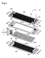
- Fig. 4 is an exploded perspective view illustrating the unit cell 10.
- the unit cell 10 includes an electrode body 217, a resin frame 300, a first separator 60 and a second separator 70.
- the electrode body 217 forms the power generation area 200g.
- the electrode body 217 includes a membrane electrode assembly 215 and a pair of gas diffusion layers 228 and 229 arranged to have respective surfaces of the membrane electrode assembly 215 placed therebetween.
- the membrane electrode assembly 215 includes an electrolyte membrane 210 and a pair of catalyst electrode layers 221 and 222 arranged to have respective surfaces of the electrolyte membrane 210 placed therebetween.
- the electrolyte membrane 210 is a polymer electrolyte membrane made of a fluorinated sulfonic acid polymer as the solid polymer material and has good proton conductivity in the wet state.
- the electrolyte membrane 210 is not limited to the fluorinated sulfonic acid membrane but may be a fluorinated phosphonic acid membrane, a fluorinated carboxylic acid membrane, a fluorinated hydrocarbon graft membrane, a hydrocarbon graft membrane or an aromatic membrane.
- the catalyst electrode layers 221 and 222 are also called cathode 221 and anode 222.
- each of the catalyst electrode layers 221 and 222 may be arranged to include a catalyst-supporting carrier (for example, carbon particles) having a catalyst metal (for example, platinum) for accelerating the electrochemical reaction supported thereon, and a polymer electrolyte (for example, fluororesin) having proton conductivity.
- the catalyst-supporting carrier is not limited to the carbon particles but may be a carbon material such as carbon black, carbon nanotube or carbon nanofiber or a carbon compound such as silicon carbide.
- the catalyst metal is not limited to platinum but may be a platinum alloy, palladium, rhodium, gold silver, osmium or iridium.
- the pair of gas diffusion layers 228 and 229 are also called cathode diffusion layer 228 and anode diffusion layer 229.
- the gas diffusion layers 228 and 229 are layers arranged to diffuse the reactive gases used for the electrode reactions along the planar direction of the electrolyte membrane 210 and are made of a porous gas diffusion layer material.
- the gas diffusion layer material may be, for example, a carbon porous body such as carbon paper or carbon cloth or a metal porous body such as metal mesh or metal foam.
- the resin frame 300 is attached to an outer periphery 200e of the electrode body 217.
- the resin frame 300 is placed between the pair of separators 60 and 70 to prevent a short circuit between the separators 60 and 70 and leakage of a fluid such as the reactive gas passing through inside of the cell module 7 to outside.
- the resin frame 300 is made of polypropylene.
- the resin frame 300 is in a sheet-like form.
- the resin frame 300 may alternatively be made of another resin such as a phenolic resin or an epoxy resin.
- the resin frame 300 has a rectangular outer shape and has an opening 310 formed in a center area to receive the electrode body 217 therein.
- the resin frame 300 has through holes 321, 322, 331, 332, 341 and 342 which respectively constitute parts of the manifolds M1 to M6 and are formed around the opening 310 of the resin frame 300. More specifically, the through hole 322 constitutes part of the manifold M1, and the through hole 342 constitutes part of the manifold M2.
- the through hole 332 constitutes part of the manifold M3, and the through hole 331 constitutes part of the manifold M4.
- the through hole 341 constitutes part of the manifold M5, and the through hole 321 constitutes part of the manifold M6.
- the resin frame 300 has groove paths 332a and 332b formed on a surface of the resin frame 300 opposed to the first separator 60.
- the groove path 332a is extended from the through hole 332 to the opening 310.
- the groove path 332a is provided as a flow path which the oxidizing gas flowing through the manifold M3 is flowed through to the electrode body 217.
- the groove path 332b is extended from the through hole 331 to the opening 310.
- the groove path 332b is provided as a flow path which the cathode off gas passing through the electrode body 217 is flowed through to the manifold M4.
- the resin frame 300 also has a first groove path (not shown) formed to extend from the through hole 322 to the opening 310 and a second groove path (not shown) formed to extend from the through hole 342 to the opening 310, on a surface of the resin frame 300 opposed to the second separator 70.
- the first groove path is provided as a flow path which the fuel gas flowing through the manifold M1 is flowed through to the electrode body 217.
- the second groove path is provided as a flow path which the fuel gas passing through the electrode body 217 is flowed through to the manifold M2.
- the groove paths 332a and 332b as well as the first groove path and the second groove path may be omitted appropriately.
- the first separator 60 and the second separator 70 are arranged to have the electrode body 217 and the resin frame 300 placed therebetween.
- the first separator 60 and the second separator 70 are bonded to the resin frame 300 using, for example, an adhesive.
- the first separator 60 is located on the cathode 221-side as one side of the membrane electrode assembly 215, and the second separator 70 is located on the anode 222-side as the other side of the membrane electrode assembly 215.
- the first and the second separators 60 and 70 are made of a material having gas cutoff performance and electrical conductivity.
- the first and the second separators 60 and 70 may be made of a carbon material such as dense carbon produced by compressing carbon particles to be gas impermeable or a metal material such as press-formed stainless steel.
- Each of the first and the second separators 60 and 70 has through holes 421, 422, 431, 432, 441 and 442 respectively constituting parts of the manifolds M1 to M6. More specifically, the through hole 422 constitutes part of the manifold M1, and the through hole 442 constitutes part of the manifold M2. The through hole 432 constitutes part of the manifold M3, and the through hole 431 constitutes part of the manifold M4. The through hole 441 constitutes part of the manifold M5, and the through hole 421 constitutes part of the manifold M6.
- the first separator 60 has a groove path 461Ca formed on a surface of the first separator 60 opposed to the electrode body 217.
- the groove path 461Ca communicates with the manifolds M3 and M4 to supply the oxidizing gas flowing through the manifold M3 to the cathode 221 of the electrode body 217 and make the cathode off gas passing through the electrode body 217 flow through to the manifold M4.
- the groove path 461Ca communicates with the manifold M3 via the groove path 332a and a groove path (not shown) formed in the separator 60.
- the groove path 461Ca communicates with the manifold M4 via the groove path 332b and a groove path (not shown) formed in the separator 60.
- the first separator 60 also has a groove path 462 formed on an opposite surface of the first separator 60 located on the opposite side to the surface opposed to the electrode body 217.
- the groove path 462 communicates with the manifolds M5 and M6 to make the cooling medium flow through.
- the second separator 70 has a groove path 461an formed on a surface of the second separator 70 opposed to the electrode body 217.
- the groove path 461an communicates with the manifolds M1 and M2 to supply the fuel gas flowing through the manifold M1 to the anode 222 of the electrode body 217 and make the anode off gas passing through the electrode body 218 flow through to the manifold M2.
- the groove path 461an communicates with the manifold M1 via a groove path 422t formed in the separator 70 and a groove path (not shown) formed in the resin frame 300.
- the groove path 461an communicates with the manifold M2 via a groove path 442t formed in the separator 70 and a groove path (not shown) formed in the resin frame 300.
- the second separator 70 also has a groove path 462 formed on an opposite surface of the second separator 70 located on the opposite side to the surface opposed to the electrode body 217.
- the groove path 462 communicates with the manifolds M5 and M6 to make the cooling medium flow through.
- Each of the first and the second separators 60 and 70 may be provided as a separator of three-layered structure.
- the separator of three-layered structure may be formed from, for example, three metal plates.
- An intermediate plate has a flow path arranged to make a flow of the cooling medium.
- Two separator plates placed across the intermediate plate respectively have an opening arranged to make a flow of the reactive gas to the electrode body 217 and an opening arranged to make a flow of the reactive gas passing through the electrode body 217 to the manifold.
- the separator of three-layered structure also has through holes respectively constituting parts of the manifolds M1 to M6.
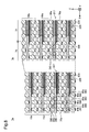
- Fig. 5 is diagrams illustrating a bonding pattern and its advantageous effects.
- the two diagrams of Fig. 5 show part of the cell module 7 taken on a plane parallel to the stacking direction (Z-axis direction) and are F3-F3 cross sectional views of Fig. 3 .
- the diagram on the left side of Fig. 5 (left diagram) illustrates the state that the cell module 7 is integrated in the fuel cell stack 200 and a predetermined load is applied to the cell module 7 from both sides in the stacking direction.
- the diagram on the right side of Fig. 5 (right diagram) illustrates the state that the predetermined load is not applied to the cell module 7.
- Fig. 5 The cross sectional views of Fig. 5 are given with a view to describing the bonding pattern in detail and may be applied to not only the cell module including the separators 60 and 70 of the above embodiment but a cell module including various separators other than the separators 60 and 70 of the above embodiment.
- the description below is on the assumption of the simplified structure of the separators 60 and 70 and the electrode body 217, in order to focus on the description of the bonding pattern.
- the bonding area 80 in which the first separator 60 and the resin frame 300 are bonded to each other is called first bonding area 80a.
- the bonding area 80 in which the second separator 60 and the resin frame 300 are bonded to each other is called second bonding area 80b.
- the bonding area 80 in which the separators 60 and 70 of the adjacent unit cells are bonded to each other is called third bonding area 80c.
- Each of the plurality of unit cells 10 constituting the cell module 7 has one first bonding area 80a, one second bonding area 80b and two third bonding areas 80c.
- the first, the second and the third bonding areas 80a, 80b and 80c are formed to surround the power generation area 200g (shown in Fig. 3 ) and to surround the through holes constituting the respective manifolds M1 to M6 (shown in Fig. 3 ), in order to prevent leakage of a fluid such as the reactive gas from the inside of the cell module 7.
- the first to the third bonding areas 80a to 80c included in at least one unit cell 10 out of the plurality of unit cells 10 may have the following pattern (called "predetermined bonding pattern").
- predetermined bonding pattern When the object unit cell 10 is viewed along the stacking direction (Z-axis direction) of the plurality of unit cells 10, the predetermined bonding pattern is that at least one bonding area of the first to the third bonding areas 80a to 80c is formed at a position that does not overlap with the positions of the other bonding areas.
- the respective unit cells 10 of the cell module 7 have a first bonding pattern of the predetermined bonding pattern.
- the first bonding pattern denotes a pattern in which the first bonding area 80a and the second bonding area 80b are formed at the positions that do not overlap with each other when the object unit cell 10 is viewed along the stacking direction (Z-axis direction).
- the third bonding area 80c is formed at a position that overlaps with the positions of both the first and the second bonding areas 80a and 80b.
- the first bonding area 80a and the second bonding area 80b are formed, on the other hand, at the positions that do not overlap with each other but are shifted from each other.
- the resin frame 300 has a deformation area 302.
- the deformation area 302 denotes a deformable area in which the separators 60 and 70 are not bonded to either of the two principal surfaces of the resin frame 300.
- the thicknesses of the gas diffusion layers 228 and 229 of the electrode body 217 increase to expand a center area 72 of the cell module 7 outward along the stacking direction. Accordingly, this increases the thickness (length along the stacking direction) of the center area 72 of the cell module 7.
- Part of a peripheral area 74 where the deformation area 302 of the resin frame 300 is located has a bowed and bent shape.
- the shape of the resin frame 300 is changed between the state that a compressive load is applied in the stacking direction and the state that the compressive load is released as described above, so that the thickness of the peripheral area 74 is increased with an increase in thickness of the center area 72. This suppresses the cell module 7 from being excessively deformed in a drum-like shape. This results in reducing the likelihood of a damage such as cracking of the cell module 7 by, for example, stress concentration.
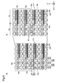
- Fig. 6 is diagrams illustrating a second bonding pattern and its advantageous effects.
- the two diagrams of Fig. 6 show part of the cell module 7 taken on the plane parallel to the stacking direction (Z-axis direction) and are F3-F3 cross sectional views of Fig. 3 .
- the left diagram of Fig. 6 corresponds to the left diagram of Fig. 5
- the right diagram of Fig. 6 corresponds to the left diagram of Fig. 5 .
- the cross sectional views of Fig. 6 are given with a view to describing the bonding pattern in detail and may be applied to not only the cell module including the separators 60 and 70 of the above embodiment but a cell module including various separators other than the separators 60 and 70 of the above embodiment.
- the description below is on the assumption of the simplified structure of the separators 60 and 70 and the electrode body 217, in order to focus on the description of the bonding pattern.
- the respective unit cells 10 of the cell module 7 may have a second bonding pattern of the predetermined bonding pattern.
- the second bonding pattern when the unit cell 10 is viewed along the stacking direction (Z-axis direction), with respect to at least one of the first and the second separators 60 and 70, the third bonding area 80c formed on one surface is arranged at a position that does not overlap with but is shifted from the position of either the first bonding area 80a or the second bonding area 80b formed on the other surface.
- the description is focused on the first separator 60 out of the first and the second separators 60 and 70 included in the unit cell 10.
- Bonding areas formed on the first separator 60 are the first bonding area 80a and the third bonding area 80c.
- the first bonding area 80a and the third bonding area 80c formed on the first separator 60 are arranged at positions that do not overlap with each other but are shifted from each other.
- bonding areas formed on the second separator 70 are the second bonding area 80b and the third bonding area 80c.
- the second bonding area 80b and the third bonding area 80c formed on the second separator 70 are arranged at positions that do not overlap with each other but are shifted from each other.
- the first and the second bonding areas 80a and 80b are formed at positions that overlap with each other
- the third bonding area 80c is formed at a position that overlaps with neither of the positions of the first and the second bonding areas 80a and 80b but is shifted from the positions of the first and the second bonding areas 80a and 80b.
- the first and the second separators 60 and 70 have deformation areas 65 and 75.
- the deformation areas 65 and 75 denote deformable areas in which no bonding area is formed on either of the two primary surfaces with respect to each of the separators 60 and 70.
- the center area 72 of the cell module 7 expands outward along the stacking direction. This results in increasing the thickness of the center area 72 of the cell module 7.
- Part of the peripheral area 74 where the deformation area 65 of the first separator 60 is located and part of the peripheral area 74 where the deformation area 75 of the second separator 70 is located have bowed and bent shapes in the stacking direction.
- the shapes of the first and the second separators 60 and 70 are changed between the state that a compressive load is applied in the stacking direction and the state that the compressive load is released as described above, so that the thickness of the peripheral area 74 is increased with an increase in thickness of the center area 72.
- Fig. 7 is diagrams illustrating a comparative example.
- a bonding pattern shown in Fig. 7 when a cell module 7 is viewed along the stacking direction (Z-axis direction) of the unit cells 10, all first to third bonding areas 80a to 80c of the cell module 7 are formed at positions that do not overlap with one another.
- the thickness of the center area 72 increases.
- the peripheral area 74 where the resin frame 300 is located, on the other hand, does not follow deformation of the center area 72, since neither of the resin frame 300, the first separator 60 and the second separator 70 is deformable in the thickness direction.
- the cell module 7 is thus likely to be excessively deformed in a drum-like shape.
- Fig. 8 is diagrams illustrating a second embodiment.
- the diagrams of Fig. 8 correspond to the diagrams of Fig. 5 .
- first and second separators 60a and 60b of each unit cell 10a have concavo-convex surface geometries.
- the concavities and the convexities on the surface form flow paths of the reactive gases and the cooling medium.
- the first and the second separators 60a and 60b may be made of, for example, a composite material of carbon particles and a resin or a material obtained by additionally mixing metal particles with the composite material. Otherwise the structure is similar to the structure of the first embodiment.
- the like components are expressed by the like symbols and are not specifically described here.
- the respective unit cells 10a have the first bonding pattern. More specifically, when the unit cell 10a is viewed along the stacking direction (Z-axis direction) of the unit cells 10a, a first bonding area 80a and a second bonding area 80b are formed at positions that do not overlap with each other but are shifted from each other. This forms a deformation area 302.
- a third bonding area 80c is formed by bonding the entire contact surfaces of the adjacent separators 60a and 70b to each other. Accordingly, the third bonding area 80c overlaps with both the first bonding area 80a and the second bonding area 80b.
- the thickness (length along the stacking direction) of the center area 72 of the cell module 7a increases.
- Part of the peripheral area 74 where the deformation area 302 of the resin frame 300 is located has a bowed and bent shape in the stacking direction.
- the shape of the resin frame 300 is changed between the state that a compressive load is applied in the stacking direction and the state that the compressive load is released as described above, so that the thickness of the peripheral area 74 is increased with an increase in thickness of the center area 72.
- Fig. 9 is diagrams illustrating a third embodiment.
- the diagrams of Fig. 9 correspond to the diagrams of Fig. 5 .
- a cell module 7b of the third embodiment differs from the cell module 7a of the second embodiment by only the bonding pattern. Otherwise the structure is similar to the structure of the second embodiment.
- the like components are expressed by the like symbols and are not specifically described here.
- the respective unit cells 10a have the second bonding pattern.
- the second bonding pattern is formed by arranging the bonding areas 80 as described below.
- a third bonding area 80c formed by bonding the adjacent unit cells 10a to each other is arranged at a position that does not overlap with the positions of first and second bonding areas 80a and 80b and is shifted from the positions of the first and the second bonding areas 80a and 80b. This forms a deformation area 65.
- the thickness (length along the stacking direction) of the center area 72 of the cell module 7b increases.
- Part of the peripheral area 74 where the deformation area 65 of the first separator 60a is located has a bowed and bent shape in the stacking direction.
- the shape of the first separator 60a is changed between the state that a compressive load is applied in the stacking direction and the state that the compressive load is released as described above, so that the thickness of the peripheral area 74 is increased with an increase in thickness of the center area 72.
- Fig. 10 is a diagram illustrating a fourth embodiment.
- the diagram of Fig. 10 corresponds to the diagram of Fig. 5 .
- Fig. 10 shows a cell module 7c in no loading state.
- the cell module 7c of the fourth embodiment differs from the cell module 7b of the third embodiment by only the structures of first and second separators 60c and 70c. Otherwise the structure is similar to the structure of the third embodiment.
- the like components are expressed by the like symbols to those of the third embodiment and are not specifically described here.
- the first and the second separators 60c and 70c of the unit cell 10c are members formed by pressing a flat metal plate. More specifically, each of the first and the second separators 60c and 70c has portions convex in a first direction (positive Z-axis direction) and portions convex in a second direction (negative Z-axis direction). These concavities the convexities form flow paths of the reactive gases and the cooling medium.
- the metal material used for formation of the first and the second separators 60c and 70c may be, for example, stainless steel.
- the first and the second separators 60c and 70c have flexibility.
- the respective unit cells 10c of the cell module 7c have the second bonding pattern. More specifically, when the unit cell 10c is viewed along the stacking direction (Z-axis direction) of the unit cells 10c, with respect to at least one of the first and the second separators 60c and 70c, a third bonding area 80c formed on one surface is arranged at a position that does not overlap with but is shifted from the position of either a first bonding area 80a or a second bonding area 80b formed on the other surface.
- the first and the second bonding areas 80a and 80b are formed at positions that overlap with each other, and the third bonding area 80c is formed at a position that does not overlap with but is shifted from the positions of the first and the second bonding areas 80a and 80b.
- the deformation areas 65 and 75 bowed and bent in the stacking direction enables the thickness of the peripheral area 74 to be changed with a change in thickness of the center area 72. This suppresses the cell module 7c from being excessively deformed in a drum-like shape. This results in reducing the likelihood of a damage such as cracking of the cell module 7c by, for example, stress concentration.
- the invention is not limited to any of the embodiments described herein but may include a diversity of modifications.
- the above embodiments are described in detail for the purpose of facilitating understanding of the invention and may not be necessarily limited to the configurations including all the components described above.
- Part of the configuration of a certain embodiment may be replaced with the configuration of another embodiment.
- the configuration of another embodiment may be added to the configuration of a certain embodiment.
- Part of the configuration of each of the embodiments may have addition of another configuration, may be deleted or may be replaced with another configuration.
- all the unit cells 10 (10a, 10c) included in the cell module 7 (7a, 7b, 7c) have either the first bonding pattern or the second bonding pattern.
- the requirement is, however, that at least one of the unit cells 10 (10a, 10c) may have either the first bonding pattern or the second bonding pattern.
- This arrangement enables the unit cell 10 (10a, 10c) of the cell module 7 (7a, 7b, 7c) having the first bonding pattern or the second bonding pattern to have a deformation area.
- This enables the peripheral area 74 to be deformed associated with deformation of the center area 72 and suppresses the cell module 7 (7a, 7b, 7c) from being excessively deformed in a drum-like shape.
- the cell module 7 (7a, 7b, 7c) may have both the first bonding pattern and the second bonding pattern. This arrangement also suppresses the cell module 7 (7a, 7b, 7c) from being excessively deformed in a drum-like shape.
- One unit cell 10 (10a, 10c) out of the plurality of unit cells 10 (10a, 10c) included in the cell module 7 (7a, 7b, 7c) may have both the first bonding pattern and the second bonding pattern. This arrangement also suppresses the cell module 7 (7a, 7b, 7c) from being excessively deformed in a drum-like shape.
- the predetermined bonding pattern is not limited to the first and the second bonding patterns.
- the first to the third bonding areas 80a to 80c may be formed at positions that do not overlap with one another but are shifted from one another. This arrangement also suppresses the cell module 7 (7a, 7b, 7c) from being excessively deformed in a drum-like shape.
- the unit cell comprises: an electrode body including a membrane electrode assembly and a pair of gas diffusion layers placed on respective surfaces of the membrane electrode assembly; a frame placed along an outer periphery of the electrode body to surround the electrode body; a first separator and a second separator bonded to the frame such as to have the electrode body and the frame placed therebetween, wherein the first separator is located on one side of the membrane electrode assembly and the second separator is located on the other side of the membrane electrode assembly; and a first bonding area provided as an area where the first separator and the frame are bonded to each other, a second bonding area provided as an area where the second separator and the frame are bonded to each other and a third bonding area provided as an area where separators included in adjacent unit cells are bonded to each other.
- At least one unit cell out of the plurality of unit cells when the at least one unit cell is viewed along a stacking direction of the plurality of unit cells, at least one bonding area out of the first to the third bonding areas is formed at a position that does not overlap with position of another bonding area.
- the at least one unit cell has a first bonding pattern.
- the first bonding area and the second bonding area are formed at positions that do not overlap with each other.
- the first bonding area and the third bonding area are arranged to at least partly overlap with each other, and the second bonding area and the third bonding area are arranged to at least partly overlap with each other.
- the unit cell comprises: an electrode body including a membrane electrode assembly and a pair of gas diffusion layers placed on respective surfaces of the membrane electrode assembly; a frame placed along an outer periphery of the electrode body to surround the electrode body; a first separator and a second separator bonded to the frame such as to have the electrode body and the frame placed therebetween, wherein the first separator is located on one side of the membrane electrode assembly and the second separator is located on the other side of the membrane electrode assembly; and a first bonding area provided as an area where the first separator and the frame are bonded to each other, a second bonding area provided as an area where the second separator and the frame are bonded to each other and a third bonding area provided as an area where separators included in adjacent unit cells are bonded to each other.
- At least one unit cell out of the plurality of unit cells when the at least one unit cell is viewed along a stacking direction of the plurality of unit cells, at least one bonding area out of the first to the third bonding areas is formed at a position that does not overlap with position of another bonding area.
- the at least one unit cell has a second bonding pattern. In the second bonding pattern, when the at least one unit cell is viewed along the stacking direction, the first bonding area and the second bonding area have an at least partly overlapped area. The overlapped area and the third bonding area are formed at positions that do not overlap with each other.
Abstract
Description
- The present invention relates to a cell module.
- A known technique forms one cell module by stacking a plurality of cells (for example,
Patent Literatures 1 to 4). A fuel cell stack is formed by stacking a plurality of such cell modules and applying a predetermined load from both sides in the stacking direction of the plurality of stacked cell modules. -
- PTL 1:
JP-A-2010-282940 - PTL 2:
JP-A-2010-080222 - PTL 3:
JP-A-2010-067453 - PTL 4:
JP-A-2010-272474 - Each cell constituting a cell module includes a membrane electrode and gas diffusion layer assembly (also called "electrode body"), a pair of separators and a frame member such as gasket. The electrode body has a membrane electrode assembly and a pair of gas diffusion layers. The pair of separators are placed to have the electrode body placed therebetween. The frame member serves to provide insulation between the separators and is placed around an outer periphery of the electrode body to prevent leakage of a fluid such as a reactive gas to outside.
- The following problems may arise when a fuel cell stack is produced by stacking a plurality of such cell modules and placing end plates on each side of the stacked cell modules. The gas diffusion layers included in each cell of the cell module are designed to have a relatively large thickness. The frame member is fixed to the outer periphery of the gas diffusion layers. Each cell module prior to being placed between the end plates as the fuel cell stack is likely to be deformed in a drum-like shape or more specifically to be expanded outward in a center area where the gas diffusion layers are located. Excessive deformation of the cell module in the drum-like shape may cause various problems. For example, this may deteriorate the sealing performance of the cell module. This may also cause a crack in each component of the cell module by, for example, stress concentration.
-
Patent Literatures 1 to 3 disclose the techniques of reducing the likelihood of the problems caused by deformation of the cell module. For example, in the technique ofPatent Literature 1, a non-bonding area where the gasket is not bonded to the separator is provided on a contact surface where the gasket is in contact with the separator. This improves the followability of gasket deformation. The technique ofPatent Literature 1, however, requires an elastic member, for example, rubber as the sealing member. Molding rubber requires a long time under a high temperature environment. This is likely to increase the manufacturing cost of the cell module. In application using thick rubber as the sealing member, the cell module may have a soft configuration and may cause a deviation from the designed location or a twist in the course of stacking a plurality of cell modules. The technique of Patent Literature 2 uses an elastic member for the gasket and may thus cause the similar problems to those ofPatent Literature 1 described above. - In the techniques of Patent Literatures 3 and 4, rubber is provided to change the interval between adjacent separators. These techniques, however, need rubber as an additional component and are likely to increase the manufacturing cost of the cell module or the fuel cell stack. In the technique of Patent Literature 3, a gasket placed around an outer periphery of an electrode body is bonded to a separator. The interval between adjacent separators is thus likely to be limited by the stretch of the gasket.
- In the cell module integrated by stacking a plurality of unit cells as described above, there is a need to suppress the cell module from being excessively deformed in a drum-like shape by the simple configuration. With respect to the cell module, other needs include resource saving, easy manufacture and improvement of usability.
- In order to solve at least part of the problems described above, the invention may be implemented by the following aspects.
- (1) According to one aspect of the invention, there is provided a cell module. The cell module comprises a plurality of unit cells that are stacked. The unit cell comprises: an electrode body including a membrane electrode assembly and a pair of gas diffusion layers placed on each surface of the membrane electrode assembly; a frame placed along an outer periphery of the electrode body to surround the electrode body; a first separator and a second separator bonded to the frame such as to have the electrode body and the frame placed therebetween, wherein the first separator is located on one side of the membrane electrode assembly and the second separator is located on the other side of the membrane electrode assembly; and a first bonding area provided as an area where the first separator and the frame are bonded to each other, a second bonding area provided as an area where the second separator and the frame are bonded to each other and a third bonding area provided as an area where separators included in adjacent unit cells are bonded to each other. With respect to at least one unit cell out of the plurality of unit cells, when the at least one unit cell is viewed along a stacking direction of the plurality of unit cells, at least one bonding area out of the first to the third bonding areas of the unit cell is formed at a position that does not overlap with another bonding area of the unit cell. The cell module of this aspect enables part of the separator or the frame to be bowed and bent in the stacking direction, even when a force is applied to the cell module in a direction of expanding the gas diffusion layers. This enables a peripheral area where the frame is located to be deformed associated with deformation of a center area where the gas diffusion layers are located. The simple configuration that at least one bonding area out of the first to the third bonding areas is formed at a position that does not overlap with the position of another bonding area suppresses the cell module from being excessively deformed in a drum-like shape.
- (2) In the cell module of the above aspect, the at least one unit cell may have a first bonding pattern. In the first bonding pattern, when the at least one unit cell is viewed along the stacking direction, the first bonding area and the second bonding area may be formed at positions that do not overlap with each other. In the cell module of this aspect, part of the frame may be bowed and bent in the stacking direction in an area where the first bonding pattern is formed.
- (3) In the cell module of the above aspect, the at least one unit cell may have a second bonding pattern. In the second bonding pattern, when the at least one unit cell is viewed along the stacking direction, with respect to at least one of the first and the second separators, the third bonding area formed on one surface may be arranged at a position that does not overlap with either the first bonding area or the second bonding area formed on the other surface. In the cell module of this aspect, part of the separator may be bowed and bent in the stacking direction in an area where the second bonding pattern is formed.
The cell module may have only one of the first and the second bonding patterns or may have both the first and the second bonding patterns. - (4) In the cell module of the above aspect, the first separator and the second separator may be metal plates. In the cell module of this aspect, the first and the second separators may be readily bendable.
- (5) In the cell module of the above aspect, the first separator and the second separator may be members including carbon particles and a resin. In the cell module of this aspect, the first and the second separators may be formed from the members including carbon particles.
- (6) According to another aspect of the invention, there is provided a fuel cell stack. The fuel cell stack comprises a plurality of the cell modules of any of the above aspects, and the plurality of the cell modules are stacked in the stacking direction. This aspect provides the fuel cell stack including the cell module configured to suppress excessive deformation in a drum-like shape.
- The invention may be implemented by any of various aspects other than those described above: for example, a manufacturing method of the cell module, a manufacturing method of the fuel cell stack or a vehicle equipped with the fuel cell stack including the cell module.
-
-
Fig. 1 is a diagram illustrating the general configuration of a fuel cell system according to a first embodiment: -
Fig. 2 is a perspective view illustrating a cell module; -
Fig. 3 is a front view illustrating the cell module; -
Fig. 4 is an exploded perspective view illustrating a unit cell; -
Fig. 5 is diagrams illustrating a first bonding pattern and its advantageous effects; -
Fig. 6 is diagrams illustrating a second bonding pattern and its advantageous effects; -
Fig. 7 is diagrams illustrating a comparative example; -
Fig. 8 is diagrams illustrating a second embodiment; -
Fig. 9 is diagrams illustrating a third embodiment; and -
Fig. 10 is a diagram illustrating a fourth embodiment. - Embodiments of the invention are described in the following sequence:
- A to D: Various Embodiments
- E. Modifications
-
Fig. 1 is a diagram illustrating the general configuration of afuel cell system 5 according to a first embodiment. Thefuel cell system 5 includes afuel cell stack 200, ahydrogen tank 50 provided to store hydrogen that is to be supplied to thefuel cell stack 200, anair compressor 40 provided to supply the compressed air to thefuel cell stack 200 and acontroller 26 configured to control the entirefuel cell system 5. - The
fuel cell stack 200 includes a plurality ofcell modules 7,end plates 21, insulatingplates 22 andcurrent collectors 23. In each of thecell modules 7, a plurality ofunit cells 10 are stacked, such thatadjacent unit cells 10 are bonded to each other. In thecell module 7, ten to fiftyunit cells 10 are stacked. Thecurrent collectors 23, the insulatingplates 22 and theend plates 21 are arranged in this sequence outward from the cell module 7-side on both sides in the stacking direction (Z-axis direction). The inside between the twoend plates 21 is fastened by a predetermined fastening power usingtension rods 24 and nuts 25. A specified load is accordingly applied from both sides in the stacking direction to each of thecell modules 7. Anactuator 27 is provided on at least one of the nuts 25 to rotate thenut 25 and adjust the fastening power. - The
unit cell 10 individually serves as a fuel cell to generate electric power. Any of various types of fuel cells may be employed for theunit cell 10. This embodiment uses a solid electrolyte fuel cell for theunit cell 10. Theunit cell 10 generates electric power by electrochemical reaction of a fuel gas (hydrogen) and an oxidizing gas (oxygen included in the air). According to this embodiment, therespective unit cells 10 have identical structures and specifications. The specific structures of theunit cell 10 and thecell module 7 will be described later. - Hydrogen as the fuel gas stored in the
hydrogen tank 50 is subjected to pressure reduction using apressure reducing valve 51 and is then flowed through a hydrogengas supply path 53. The flow of hydrogen is adjusted to have a predetermined pressure by apressure regulator 52 provided in the hydrogengas supply path 53 and is supplied to thefuel cell stack 200. A hydrogen-containing gas (anode feed gas) supplied to thefuel cell stack 200 is supplied via an anode gas supply manifold (not shown) provided inside of thefuel cell stack 200 to therespective unit cells 10 and is used for power generation in therespective unit cells 10. A gas containing hydrogen unused in the respective unit cells 10 (anode off gas) is collected via an anode gas exhaust manifold (not shown) provided inside of thefuel cell stack 200. The anode off gas is then discharged out of thefuel cell stack 200 via an anode offgas passage 54. Thefuel cell system 5 may be configured to recirculate the anode off gas to the supply side. - The
air compressor 40 serves to pressurize the air taken in from the outside as the oxidizing gas. The pressurized air is supplied via an oxidizinggas supply path 41 to thefuel cell stack 200. The oxygen-containing air (cathode feed gas) supplied to thefuel cell stack 200 is supplied via a cathode gas supply manifold (not shown) to therespective unit cells 10 and is used for power generation in therespective unit cells 10. The air unused in the respective cells 10 (cathode off gas) is collected via a cathode gas exhaust manifold (not shown) and is discharged out of thefuel cell stack 200 via a cathode offgas passage 48. - A cooling
medium circulation pump 46 serves to supply a cooling medium via a coolingmedium circulation path 47 to thefuel cell stack 200. The cooling medium warmed by thefuel cell stack 200 is cooled down by aradiator 45 and is supplied again to thefuel cell stack 200. The cooling medium is supplied via a cooling medium supply manifold (not shown) to therespective unit cells 10 to cool down therespective unit cells 10. After passing through therespective unit cells 10, the cooling medium is collected via a cooling medium exhaust manifold (not shown) and is flowed through a coolingmedium circulation path 43 into theradiator 45. The cooling medium may be water or an antifreeze liquid such as mixed liquid of water and ethylene glycol. This embodiment uses a liquid as the cooling medium, but the air may alternatively be used as the cooling medium. - The
controller 26 is a computer including a CPU and memories (not shown). Thecontroller 26 receives signals from, for example, temperature sensors, pressure sensors and voltmeters located in the respective parts of thefuel cell system 5 and controls the entirefuel cell system 5 based on the received signals. -
Fig. 2 is a perspective view illustrating thecell module 7.Fig. 3 is a front view illustrating thecell module 7. Thecell module 7 is formed by stacking a plurality of theunit cells 10 and bondingadjacent unit cells 10 to each other. Theadjacent unit cells 10 may be bonded to each other, for example, by using an adhesive. Thecell module 7 has manifolds M1 to M6 which the reactive gases (fuel gas and oxidizing gas) and the cooling medium are flowed through in the stacking direction (Z-axis direction). More specifically, the anode feed gas (hydrogen) is flowed through the manifold M1. The anode off gas is flowed through the manifold M2. The cathode feed gas (air) is flowed through the manifold M3. The cathode off gas is flowed through the manifold M4. The cooling medium supplied from outside is flowed through the manifold M5. The cooling medium passing through theunit cell 10 is flowed through the manifold M6. As shown inFig. 3 , apower generation area 200g is formed in an inner area surrounded by the respective manifolds M1 to M6. - The
unit cell 10 has a bonding area where a first separator and a resin frame are bonded to each other, a bonding area where a second separator and the resin frame are bonded and a bonding area whereadjacent unit cells 10 are bonded to each other, as described in detail later. These three bonding areas are formed such as to surround thepower generation area 200g and to surround through holes constituting the respective manifolds M1 to M6. - In the
fuel cell stack 200 formed by stacking a plurality of thecell modules 7, agasket 16 is placed betweenadjacent cell modules 7. Placing thegasket 16 to be in close contact with the twoadjacent cell modules 7 prevents leakage of the reactive gases and the cooling medium to outside. -
Fig. 4 is an exploded perspective view illustrating theunit cell 10. Theunit cell 10 includes anelectrode body 217, aresin frame 300, afirst separator 60 and asecond separator 70. Theelectrode body 217 forms thepower generation area 200g. Theelectrode body 217 includes amembrane electrode assembly 215 and a pair of gas diffusion layers 228 and 229 arranged to have respective surfaces of themembrane electrode assembly 215 placed therebetween. - The
membrane electrode assembly 215 includes anelectrolyte membrane 210 and a pair of catalyst electrode layers 221 and 222 arranged to have respective surfaces of theelectrolyte membrane 210 placed therebetween. Theelectrolyte membrane 210 is a polymer electrolyte membrane made of a fluorinated sulfonic acid polymer as the solid polymer material and has good proton conductivity in the wet state. Theelectrolyte membrane 210 is not limited to the fluorinated sulfonic acid membrane but may be a fluorinated phosphonic acid membrane, a fluorinated carboxylic acid membrane, a fluorinated hydrocarbon graft membrane, a hydrocarbon graft membrane or an aromatic membrane. - The catalyst electrode layers 221 and 222 are also called
cathode 221 andanode 222. For example, each of the catalyst electrode layers 221 and 222 may be arranged to include a catalyst-supporting carrier (for example, carbon particles) having a catalyst metal (for example, platinum) for accelerating the electrochemical reaction supported thereon, and a polymer electrolyte (for example, fluororesin) having proton conductivity. The catalyst-supporting carrier is not limited to the carbon particles but may be a carbon material such as carbon black, carbon nanotube or carbon nanofiber or a carbon compound such as silicon carbide. The catalyst metal is not limited to platinum but may be a platinum alloy, palladium, rhodium, gold silver, osmium or iridium. - The pair of gas diffusion layers 228 and 229 are also called
cathode diffusion layer 228 andanode diffusion layer 229. The gas diffusion layers 228 and 229 are layers arranged to diffuse the reactive gases used for the electrode reactions along the planar direction of theelectrolyte membrane 210 and are made of a porous gas diffusion layer material. The gas diffusion layer material may be, for example, a carbon porous body such as carbon paper or carbon cloth or a metal porous body such as metal mesh or metal foam. - The
resin frame 300 is attached to anouter periphery 200e of theelectrode body 217. Theresin frame 300 is placed between the pair ofseparators separators cell module 7 to outside. Theresin frame 300 is made of polypropylene. Theresin frame 300 is in a sheet-like form. Theresin frame 300 may alternatively be made of another resin such as a phenolic resin or an epoxy resin. - The
resin frame 300 has a rectangular outer shape and has anopening 310 formed in a center area to receive theelectrode body 217 therein. Theresin frame 300 has throughholes opening 310 of theresin frame 300. More specifically, the throughhole 322 constitutes part of the manifold M1, and the throughhole 342 constitutes part of the manifold M2. The throughhole 332 constitutes part of the manifold M3, and the throughhole 331 constitutes part of the manifold M4. The throughhole 341 constitutes part of the manifold M5, and the throughhole 321 constitutes part of the manifold M6. - The
resin frame 300 hasgroove paths resin frame 300 opposed to thefirst separator 60. Thegroove path 332a is extended from the throughhole 332 to theopening 310. Thegroove path 332a is provided as a flow path which the oxidizing gas flowing through the manifold M3 is flowed through to theelectrode body 217. Thegroove path 332b is extended from the throughhole 331 to theopening 310. Thegroove path 332b is provided as a flow path which the cathode off gas passing through theelectrode body 217 is flowed through to the manifold M4. Theresin frame 300 also has a first groove path (not shown) formed to extend from the throughhole 322 to theopening 310 and a second groove path (not shown) formed to extend from the throughhole 342 to theopening 310, on a surface of theresin frame 300 opposed to thesecond separator 70. The first groove path is provided as a flow path which the fuel gas flowing through the manifold M1 is flowed through to theelectrode body 217. The second groove path is provided as a flow path which the fuel gas passing through theelectrode body 217 is flowed through to the manifold M2. Thegroove paths - The
first separator 60 and thesecond separator 70 are arranged to have theelectrode body 217 and theresin frame 300 placed therebetween. Thefirst separator 60 and thesecond separator 70 are bonded to theresin frame 300 using, for example, an adhesive. Thefirst separator 60 is located on the cathode 221-side as one side of themembrane electrode assembly 215, and thesecond separator 70 is located on the anode 222-side as the other side of themembrane electrode assembly 215. - The first and the
second separators second separators - Each of the first and the
second separators holes hole 422 constitutes part of the manifold M1, and the throughhole 442 constitutes part of the manifold M2. The throughhole 432 constitutes part of the manifold M3, and the throughhole 431 constitutes part of the manifold M4. The throughhole 441 constitutes part of the manifold M5, and the throughhole 421 constitutes part of the manifold M6. - The
first separator 60 has a groove path 461Ca formed on a surface of thefirst separator 60 opposed to theelectrode body 217. The groove path 461Ca communicates with the manifolds M3 and M4 to supply the oxidizing gas flowing through the manifold M3 to thecathode 221 of theelectrode body 217 and make the cathode off gas passing through theelectrode body 217 flow through to the manifold M4. The groove path 461Ca communicates with the manifold M3 via thegroove path 332a and a groove path (not shown) formed in theseparator 60. The groove path 461Ca communicates with the manifold M4 via thegroove path 332b and a groove path (not shown) formed in theseparator 60. Thefirst separator 60 also has agroove path 462 formed on an opposite surface of thefirst separator 60 located on the opposite side to the surface opposed to theelectrode body 217. Thegroove path 462 communicates with the manifolds M5 and M6 to make the cooling medium flow through. - The
second separator 70 has a groove path 461an formed on a surface of thesecond separator 70 opposed to theelectrode body 217. The groove path 461an communicates with the manifolds M1 and M2 to supply the fuel gas flowing through the manifold M1 to theanode 222 of theelectrode body 217 and make the anode off gas passing through the electrode body 218 flow through to the manifold M2. The groove path 461an communicates with the manifold M1 via a groove path 422t formed in theseparator 70 and a groove path (not shown) formed in theresin frame 300. The groove path 461an communicates with the manifold M2 via agroove path 442t formed in theseparator 70 and a groove path (not shown) formed in theresin frame 300. Thesecond separator 70 also has agroove path 462 formed on an opposite surface of thesecond separator 70 located on the opposite side to the surface opposed to theelectrode body 217. Thegroove path 462 communicates with the manifolds M5 and M6 to make the cooling medium flow through. - Each of the first and the
second separators electrode body 217 and an opening arranged to make a flow of the reactive gas passing through theelectrode body 217 to the manifold. The separator of three-layered structure also has through holes respectively constituting parts of the manifolds M1 to M6. - The following describes the positional relationship of
bonding areas 80 in which the respective components are bonded to each other in theabove cell module 7.Fig. 5 is diagrams illustrating a bonding pattern and its advantageous effects. The two diagrams ofFig. 5 show part of thecell module 7 taken on a plane parallel to the stacking direction (Z-axis direction) and are F3-F3 cross sectional views ofFig. 3 . The diagram on the left side ofFig. 5 (left diagram) illustrates the state that thecell module 7 is integrated in thefuel cell stack 200 and a predetermined load is applied to thecell module 7 from both sides in the stacking direction. The diagram on the right side ofFig. 5 (right diagram) illustrates the state that the predetermined load is not applied to thecell module 7. The cross sectional views ofFig. 5 are given with a view to describing the bonding pattern in detail and may be applied to not only the cell module including theseparators separators separators electrode body 217, in order to focus on the description of the bonding pattern. - The
bonding area 80 in which thefirst separator 60 and theresin frame 300 are bonded to each other is calledfirst bonding area 80a. Thebonding area 80 in which thesecond separator 60 and theresin frame 300 are bonded to each other is calledsecond bonding area 80b. Thebonding area 80 in which theseparators third bonding area 80c. Each of the plurality ofunit cells 10 constituting thecell module 7 has onefirst bonding area 80a, onesecond bonding area 80b and twothird bonding areas 80c. The first, the second and thethird bonding areas power generation area 200g (shown inFig. 3 ) and to surround the through holes constituting the respective manifolds M1 to M6 (shown inFig. 3 ), in order to prevent leakage of a fluid such as the reactive gas from the inside of thecell module 7. - The first to the
third bonding areas 80a to 80c included in at least oneunit cell 10 out of the plurality ofunit cells 10 may have the following pattern (called "predetermined bonding pattern"). When theobject unit cell 10 is viewed along the stacking direction (Z-axis direction) of the plurality ofunit cells 10, the predetermined bonding pattern is that at least one bonding area of the first to thethird bonding areas 80a to 80c is formed at a position that does not overlap with the positions of the other bonding areas. - In the illustrated example of
Fig. 5 , therespective unit cells 10 of thecell module 7 have a first bonding pattern of the predetermined bonding pattern. The first bonding pattern denotes a pattern in which thefirst bonding area 80a and thesecond bonding area 80b are formed at the positions that do not overlap with each other when theobject unit cell 10 is viewed along the stacking direction (Z-axis direction). In the example ofFig. 5 , thethird bonding area 80c is formed at a position that overlaps with the positions of both the first and thesecond bonding areas first bonding area 80a and thesecond bonding area 80b are formed, on the other hand, at the positions that do not overlap with each other but are shifted from each other. When theunit cell 10 has the first bonding pattern, theresin frame 300 has adeformation area 302. Thedeformation area 302 denotes a deformable area in which theseparators resin frame 300. - As shown in the right diagram of
Fig. 5 , when thecell module 7 is in no loading state, the thicknesses of the gas diffusion layers 228 and 229 of theelectrode body 217 increase to expand acenter area 72 of thecell module 7 outward along the stacking direction. Accordingly, this increases the thickness (length along the stacking direction) of thecenter area 72 of thecell module 7. Part of aperipheral area 74 where thedeformation area 302 of theresin frame 300 is located has a bowed and bent shape. The shape of theresin frame 300 is changed between the state that a compressive load is applied in the stacking direction and the state that the compressive load is released as described above, so that the thickness of theperipheral area 74 is increased with an increase in thickness of thecenter area 72. This suppresses thecell module 7 from being excessively deformed in a drum-like shape. This results in reducing the likelihood of a damage such as cracking of thecell module 7 by, for example, stress concentration. -
Fig. 6 is diagrams illustrating a second bonding pattern and its advantageous effects. The two diagrams ofFig. 6 show part of thecell module 7 taken on the plane parallel to the stacking direction (Z-axis direction) and are F3-F3 cross sectional views ofFig. 3 . The left diagram ofFig. 6 corresponds to the left diagram ofFig. 5 , and the right diagram ofFig. 6 corresponds to the left diagram ofFig. 5 . The cross sectional views ofFig. 6 are given with a view to describing the bonding pattern in detail and may be applied to not only the cell module including theseparators separators separators electrode body 217, in order to focus on the description of the bonding pattern. - The
respective unit cells 10 of thecell module 7 may have a second bonding pattern of the predetermined bonding pattern. In the second bonding pattern, when theunit cell 10 is viewed along the stacking direction (Z-axis direction), with respect to at least one of the first and thesecond separators third bonding area 80c formed on one surface is arranged at a position that does not overlap with but is shifted from the position of either thefirst bonding area 80a or thesecond bonding area 80b formed on the other surface. - In the illustrated example of
Fig. 6 , the description is focused on thefirst separator 60 out of the first and thesecond separators unit cell 10. Bonding areas formed on thefirst separator 60 are thefirst bonding area 80a and thethird bonding area 80c. In the second bonding pattern, thefirst bonding area 80a and thethird bonding area 80c formed on thefirst separator 60 are arranged at positions that do not overlap with each other but are shifted from each other. When the description is focused on thesecond separator 70, bonding areas formed on thesecond separator 70 are thesecond bonding area 80b and thethird bonding area 80c. In the second bonding pattern, thesecond bonding area 80b and thethird bonding area 80c formed on thesecond separator 70 are arranged at positions that do not overlap with each other but are shifted from each other. In the illustrated example ofFig. 6 , when theunit cell 10 is viewed along the stacking direction (Z-axis direction), the first and thesecond bonding areas third bonding area 80c is formed at a position that overlaps with neither of the positions of the first and thesecond bonding areas second bonding areas - As described above, when the
unit cell 10 has the second bonding pattern, the first and thesecond separators deformation areas deformation areas separators - As shown in the right diagram of
Fig. 6 , when thecell module 7 is in no loading state, thecenter area 72 of thecell module 7 expands outward along the stacking direction. This results in increasing the thickness of thecenter area 72 of thecell module 7. Part of theperipheral area 74 where thedeformation area 65 of thefirst separator 60 is located and part of theperipheral area 74 where thedeformation area 75 of thesecond separator 70 is located have bowed and bent shapes in the stacking direction. The shapes of the first and thesecond separators peripheral area 74 is increased with an increase in thickness of thecenter area 72. This suppresses thecell module 7 from being excessively deformed in a drum-like shape. This results in reducing the likelihood of a damage such as cracking of thecell module 7 by, for example, stress concentration. -
Fig. 7 is diagrams illustrating a comparative example. In a bonding pattern shown inFig. 7 , when acell module 7 is viewed along the stacking direction (Z-axis direction) of theunit cells 10, all first tothird bonding areas 80a to 80c of thecell module 7 are formed at positions that do not overlap with one another. As shown in the right diagram ofFig. 7 , when thecell module 7 is in no loading state, the thickness of thecenter area 72 increases. Theperipheral area 74 where theresin frame 300 is located, on the other hand, does not follow deformation of thecenter area 72, since neither of theresin frame 300, thefirst separator 60 and thesecond separator 70 is deformable in the thickness direction. Thecell module 7 is thus likely to be excessively deformed in a drum-like shape. -
Fig. 8 is diagrams illustrating a second embodiment. The diagrams ofFig. 8 correspond to the diagrams ofFig. 5 . In acell module 7a shown inFig. 8 , first andsecond separators 60a and 60b of eachunit cell 10a have concavo-convex surface geometries. The concavities and the convexities on the surface form flow paths of the reactive gases and the cooling medium. The first and thesecond separators 60a and 60b may be made of, for example, a composite material of carbon particles and a resin or a material obtained by additionally mixing metal particles with the composite material. Otherwise the structure is similar to the structure of the first embodiment. The like components are expressed by the like symbols and are not specifically described here. - In the
cell module 7a shown inFig. 8 , therespective unit cells 10a have the first bonding pattern. More specifically, when theunit cell 10a is viewed along the stacking direction (Z-axis direction) of theunit cells 10a, afirst bonding area 80a and asecond bonding area 80b are formed at positions that do not overlap with each other but are shifted from each other. This forms adeformation area 302. Athird bonding area 80c is formed by bonding the entire contact surfaces of theadjacent separators 60a and 70b to each other. Accordingly, thethird bonding area 80c overlaps with both thefirst bonding area 80a and thesecond bonding area 80b. - As shown in the right diagram of
Fig. 8 , when thecell module 7a is in no loading state, the thickness (length along the stacking direction) of thecenter area 72 of thecell module 7a increases. Part of theperipheral area 74 where thedeformation area 302 of theresin frame 300 is located has a bowed and bent shape in the stacking direction. The shape of theresin frame 300 is changed between the state that a compressive load is applied in the stacking direction and the state that the compressive load is released as described above, so that the thickness of theperipheral area 74 is increased with an increase in thickness of thecenter area 72. This suppresses thecell module 7a from being excessively deformed in a drum-like shape. This results in reducing the likelihood of a damage such as cracking of thecell module 7a by, for example, stress concentration. -
Fig. 9 is diagrams illustrating a third embodiment. The diagrams ofFig. 9 correspond to the diagrams ofFig. 5 . Acell module 7b of the third embodiment differs from thecell module 7a of the second embodiment by only the bonding pattern. Otherwise the structure is similar to the structure of the second embodiment. The like components are expressed by the like symbols and are not specifically described here. - In the
cell module 7b, therespective unit cells 10a have the second bonding pattern. According to the third embodiment, the second bonding pattern is formed by arranging thebonding areas 80 as described below. When each of theunit cells 10a is viewed in the stacking direction of theunit cells 10a, athird bonding area 80c formed by bonding theadjacent unit cells 10a to each other is arranged at a position that does not overlap with the positions of first andsecond bonding areas second bonding areas deformation area 65. - As shown in the right diagram of
Fig. 9 , when thecell module 7a is in no loading state, the thickness (length along the stacking direction) of thecenter area 72 of thecell module 7b increases. Part of theperipheral area 74 where thedeformation area 65 of thefirst separator 60a is located has a bowed and bent shape in the stacking direction. The shape of thefirst separator 60a is changed between the state that a compressive load is applied in the stacking direction and the state that the compressive load is released as described above, so that the thickness of theperipheral area 74 is increased with an increase in thickness of thecenter area 72. This suppresses thecell module 7a from being excessively deformed in a drum-like shape. This results in reducing the likelihood of a damage such as cracking of thecell module 7a by, for example, stress concentration. -
Fig. 10 is a diagram illustrating a fourth embodiment. The diagram ofFig. 10 corresponds to the diagram ofFig. 5 .Fig. 10 shows acell module 7c in no loading state. Thecell module 7c of the fourth embodiment differs from thecell module 7b of the third embodiment by only the structures of first andsecond separators - In the
cell module 7c, the first and thesecond separators unit cell 10c are members formed by pressing a flat metal plate. More specifically, each of the first and thesecond separators second separators second separators - The
respective unit cells 10c of thecell module 7c have the second bonding pattern. More specifically, when theunit cell 10c is viewed along the stacking direction (Z-axis direction) of theunit cells 10c, with respect to at least one of the first and thesecond separators third bonding area 80c formed on one surface is arranged at a position that does not overlap with but is shifted from the position of either afirst bonding area 80a or asecond bonding area 80b formed on the other surface. According to this embodiment, in each of theunit cells 10c, the first and thesecond bonding areas third bonding area 80c is formed at a position that does not overlap with but is shifted from the positions of the first and thesecond bonding areas deformation areas deformation areas peripheral area 74 to be changed with a change in thickness of thecenter area 72. This suppresses thecell module 7c from being excessively deformed in a drum-like shape. This results in reducing the likelihood of a damage such as cracking of thecell module 7c by, for example, stress concentration. - The invention is not limited to any of the embodiments described herein but may include a diversity of modifications. For example, the above embodiments are described in detail for the purpose of facilitating understanding of the invention and may not be necessarily limited to the configurations including all the components described above. Part of the configuration of a certain embodiment may be replaced with the configuration of another embodiment. The configuration of another embodiment may be added to the configuration of a certain embodiment. Part of the configuration of each of the embodiments may have addition of another configuration, may be deleted or may be replaced with another configuration.
- In the embodiments described above, all the unit cells 10 (10a, 10c) included in the cell module 7 (7a, 7b, 7c) have either the first bonding pattern or the second bonding pattern. The requirement is, however, that at least one of the unit cells 10 (10a, 10c) may have either the first bonding pattern or the second bonding pattern. This arrangement enables the unit cell 10 (10a, 10c) of the cell module 7 (7a, 7b, 7c) having the first bonding pattern or the second bonding pattern to have a deformation area. This enables the
peripheral area 74 to be deformed associated with deformation of thecenter area 72 and suppresses the cell module 7 (7a, 7b, 7c) from being excessively deformed in a drum-like shape. - The cell module 7 (7a, 7b, 7c) may have both the first bonding pattern and the second bonding pattern. This arrangement also suppresses the cell module 7 (7a, 7b, 7c) from being excessively deformed in a drum-like shape.
- One unit cell 10 (10a, 10c) out of the plurality of unit cells 10 (10a, 10c) included in the cell module 7 (7a, 7b, 7c) may have both the first bonding pattern and the second bonding pattern. This arrangement also suppresses the cell module 7 (7a, 7b, 7c) from being excessively deformed in a drum-like shape.
- The predetermined bonding pattern is not limited to the first and the second bonding patterns. For example, in another example of the predetermined bonding pattern, when the unit cell 10 (10a,10c) is viewed along the stacking direction (Z-axis direction), the first to the
third bonding areas 80a to 80c may be formed at positions that do not overlap with one another but are shifted from one another. This arrangement also suppresses the cell module 7 (7a, 7b, 7c) from being excessively deformed in a drum-like shape. - The above embodiments may employ the following aspects:
- There is a cell module, comprising a plurality of unit cells that are stacked. The unit cell comprises: an electrode body including a membrane electrode assembly and a pair of gas diffusion layers placed on respective surfaces of the membrane electrode assembly; a frame placed along an outer periphery of the electrode body to surround the electrode body; a first separator and a second separator bonded to the frame such as to have the electrode body and the frame placed therebetween, wherein the first separator is located on one side of the membrane electrode assembly and the second separator is located on the other side of the membrane electrode assembly; and a first bonding area provided as an area where the first separator and the frame are bonded to each other, a second bonding area provided as an area where the second separator and the frame are bonded to each other and a third bonding area provided as an area where separators included in adjacent unit cells are bonded to each other. With respect to at least one unit cell out of the plurality of unit cells, when the at least one unit cell is viewed along a stacking direction of the plurality of unit cells, at least one bonding area out of the first to the third bonding areas is formed at a position that does not overlap with position of another bonding area. The at least one unit cell has a first bonding pattern. In the first bonding pattern, when the at least one unit cell is viewed along the stacking direction, the first bonding area and the second bonding area are formed at positions that do not overlap with each other. The first bonding area and the third bonding area are arranged to at least partly overlap with each other, and the second bonding area and the third bonding area are arranged to at least partly overlap with each other.
- There is a cell module, comprising a plurality of unit cells that are stacked. The unit cell comprises: an electrode body including a membrane electrode assembly and a pair of gas diffusion layers placed on respective surfaces of the membrane electrode assembly; a frame placed along an outer periphery of the electrode body to surround the electrode body; a first separator and a second separator bonded to the frame such as to have the electrode body and the frame placed therebetween, wherein the first separator is located on one side of the membrane electrode assembly and the second separator is located on the other side of the membrane electrode assembly; and a first bonding area provided as an area where the first separator and the frame are bonded to each other, a second bonding area provided as an area where the second separator and the frame are bonded to each other and a third bonding area provided as an area where separators included in adjacent unit cells are bonded to each other. With respect to at least one unit cell out of the plurality of unit cells, when the at least one unit cell is viewed along a stacking direction of the plurality of unit cells, at least one bonding area out of the first to the third bonding areas is formed at a position that does not overlap with position of another bonding area. The at least one unit cell has a second bonding pattern. In the second bonding pattern, when the at least one unit cell is viewed along the stacking direction, the first bonding area and the second bonding area have an at least partly overlapped area. The overlapped area and the third bonding area are formed at positions that do not overlap with each other.
-
- 5
- fuel cell system
- 7 to 7c
- cell modules
- 10 to 10c
- unit cells
- 16
- gasket
- 21
- end plate
- 22
- insulating plate
- 23
- current collector
- 24
- tension rod
- 25
- nut
- 26
- controller
- 27
- actuator
- 40
- air compressor
- 41
- oxidizing gas supply path
- 43
- cooling medium circulation path
- 45
- radiator
- 47
- cooling medium circulation path
- 48
- cathode off gas passage
- 50
- hydrogen tank
- 51
- pressure reducing valve
- 52
- pressure regulator
- 53
- hydrogen gas supply path
- 54
- anode off gas passage
- 60 to 60c
- first separators
- 65
- deformation area
- 70 to 70c
- second separators
- 72
- center area
- 74
- peripheral area
- 75
- deformation area
- 80
- bonding area
- 80a
- first bonding area
- 80b
- second bonding area
- 80c
- third bonding area
- 200
- fuel cell stack
- 200e
- outer periphery
- 200g
- power generation area
- 210
- electrolyte membrane
- 215
- membrane electrode assembly
- 217
- electrode body
- 221
- cathode
- 222
- anode
- 228
- cathode diffusion layer
- 229
- anode diffusion layer
- 300
- resin frame
- 302
- deformation area
- 310
- opening
- 321, 322, 331, 332
- through holes
- 332a
- groove path
- 332b
- groove path
- 341, 342, 421, 422
- through holes
- 422t
- groove path
- 431, 432, 441, 442
- through holes
- 442t
- groove path
- 461Ca
- groove path
- 461an
- groove path
- 462
- groove path
- M1 to M6
- manifolds
Claims (6)
- A cell module, comprising a plurality of unit cells that are stacked, the unit cell comprising:an electrode body including a membrane electrode assembly and a pair of gas diffusion layers placed on each surface of the membrane electrode assembly;a frame placed along an outer periphery of the electrode body to surround the electrode body;a first separator and a second separator bonded to the frame such as to have the electrode body and the frame placed therebetween, wherein the first separator is located on one side of the membrane electrode assembly and the second separator is located on the other side of the membrane electrode assembly; anda first bonding area provided as an area where the first separator and the frame are bonded to each other, a second bonding area provided as an area where the second separator and the frame are bonded to each other and a third bonding area provided as an area where separators included in adjacent unit cells are bonded to each other, whereinwith respect to at least one unit cell out of the plurality of unit cells, when the at least one unit cell is viewed along a stacking direction of the plurality of unit cells, at least one bonding area out of the first to the third bonding areas of the unit cell is formed at a position that does not overlap with another bonding area of the unit cell.
- The cell module according to claim 1,
wherein the at least one unit cell has a first bonding pattern, and
in the first bonding pattern, when the at least one unit cell is viewed along the stacking direction, the first bonding area and the second bonding area are formed at positions that do not overlap with each other. - The cell module according to either claim 1 or claim 2,
wherein the at least one unit cell has a second bonding pattern, and
in the second bonding pattern, when the at least one unit cell is viewed along the stacking direction, with respect to at least one of the first and the second separators, the third bonding area formed on one surface is arranged at a position that does not overlap with either the first bonding area or the second bonding area formed on the other surface. - The cell module according to any one of claims 1 to 3,
wherein the first separator and the second separator are metal plates. - The cell module according to any one of claims 1 to 3,
wherein the first separator and the second separator are members including carbon particles and a resin. - A fuel cell stack, comprising:a plurality of the cell modules according to any one of claims 1 to 5, whereinthe plurality of the cell modules are stacked in the stacking direction.
Applications Claiming Priority (2)
| Application Number | Priority Date | Filing Date | Title |
|---|---|---|---|
| JP2012242346A JP5708614B2 (en) | 2012-11-02 | 2012-11-02 | Cell module and fuel cell stack |
| PCT/JP2013/005975 WO2014068854A1 (en) | 2012-11-02 | 2013-10-08 | Cell module and fuel cell stack |
Publications (3)
| Publication Number | Publication Date |
|---|---|
| EP2916376A1 true EP2916376A1 (en) | 2015-09-09 |
| EP2916376A4 EP2916376A4 (en) | 2016-02-17 |
| EP2916376B1 EP2916376B1 (en) | 2017-06-21 |
Family
ID=50626809
Family Applications (1)
| Application Number | Title | Priority Date | Filing Date |
|---|---|---|---|
| EP13851983.0A Active EP2916376B1 (en) | 2012-11-02 | 2013-10-08 | Cell module and fuel cell stack |
Country Status (5)
| Country | Link |
|---|---|
| US (1) | US9525188B2 (en) |
| EP (1) | EP2916376B1 (en) |
| JP (1) | JP5708614B2 (en) |
| CN (1) | CN104769761B (en) |
| WO (1) | WO2014068854A1 (en) |
Cited By (1)
| Publication number | Priority date | Publication date | Assignee | Title |
|---|---|---|---|---|
| EP3306721A4 (en) * | 2015-06-03 | 2018-05-23 | Nissan Motor Co., Ltd. | Metal separator structure body for fuel cell, fuel cell and fuel cell stack using same separator structure body |
Families Citing this family (7)
| Publication number | Priority date | Publication date | Assignee | Title |
|---|---|---|---|---|
| CN105313898B (en) | 2014-07-23 | 2018-03-20 | 现代摩比斯株式会社 | Driver status induction installation and its method |
| US10326150B2 (en) | 2014-08-26 | 2019-06-18 | Panasonic Intellectual Property Management Co., Ltd. | Fuel cell module, fuel cell stack, and method for producing fuel cell module |
| CA3001093C (en) * | 2015-10-05 | 2019-03-12 | Nissan Motor Co., Ltd. | Fuel cell stack with overlapping portion to transmit and support reaction force |
| JP6628166B2 (en) * | 2016-07-14 | 2020-01-08 | 日産自動車株式会社 | Fuel cell stack |
| JP6756294B2 (en) * | 2017-04-10 | 2020-09-16 | トヨタ自動車株式会社 | Fuel cell stack and fuel cell stack manufacturing method |
| JP7302532B2 (en) * | 2020-05-28 | 2023-07-04 | トヨタ自動車株式会社 | fuel cell |
| JP7310786B2 (en) * | 2020-11-20 | 2023-07-19 | トヨタ自動車株式会社 | Fuel cell |
Citations (4)
| Publication number | Priority date | Publication date | Assignee | Title |
|---|---|---|---|---|
| EP1087454A1 (en) * | 1999-09-22 | 2001-03-28 | Nisshinbo Industries, Inc. | Fuel cell separator and production method thereof |
| WO2010058258A1 (en) * | 2008-11-19 | 2010-05-27 | Nissan Motor Co., Ltd. | Fuel cell stack |
| WO2012137773A1 (en) * | 2011-04-05 | 2012-10-11 | 日産自動車株式会社 | Fuel cell |
| WO2013140855A1 (en) * | 2012-03-23 | 2013-09-26 | 本田技研工業株式会社 | Fuel cell |
Family Cites Families (9)
| Publication number | Priority date | Publication date | Assignee | Title |
|---|---|---|---|---|
| JP5011759B2 (en) * | 2006-03-07 | 2012-08-29 | トヨタ自動車株式会社 | Fuel cell with cell voltage monitor |
| JP5109277B2 (en) * | 2006-03-30 | 2012-12-26 | トヨタ自動車株式会社 | Multi-cell module and fuel cell stack |
| KR100839193B1 (en) * | 2008-01-21 | 2008-06-17 | 현대하이스코 주식회사 | Metallic bipolar plate having surface layer which carbon particles dispersed in the binder polymer for fuel cell and its manufacturing method |
| JP5181950B2 (en) | 2008-09-10 | 2013-04-10 | トヨタ自動車株式会社 | Fuel cell |
| JP5181969B2 (en) | 2008-09-25 | 2013-04-10 | トヨタ自動車株式会社 | Fuel cell |
| JP5077290B2 (en) * | 2009-05-25 | 2012-11-21 | 日産自動車株式会社 | Fuel cell module and manufacturing method thereof |
| JP2010282940A (en) * | 2009-06-08 | 2010-12-16 | Toyota Motor Corp | Fuel cell |
| EP2461404B1 (en) * | 2009-07-27 | 2019-12-11 | Panasonic Intellectual Property Management Co., Ltd. | Fuel cell stack |
| WO2011114811A1 (en) * | 2010-03-17 | 2011-09-22 | 日産自動車株式会社 | Fuel cell |
-
2012
- 2012-11-02 JP JP2012242346A patent/JP5708614B2/en active Active
-
2013
- 2013-10-08 EP EP13851983.0A patent/EP2916376B1/en active Active
- 2013-10-08 CN CN201380057486.6A patent/CN104769761B/en active Active
- 2013-10-08 WO PCT/JP2013/005975 patent/WO2014068854A1/en active Application Filing
- 2013-10-08 US US14/439,348 patent/US9525188B2/en active Active
Patent Citations (4)
| Publication number | Priority date | Publication date | Assignee | Title |
|---|---|---|---|---|
| EP1087454A1 (en) * | 1999-09-22 | 2001-03-28 | Nisshinbo Industries, Inc. | Fuel cell separator and production method thereof |
| WO2010058258A1 (en) * | 2008-11-19 | 2010-05-27 | Nissan Motor Co., Ltd. | Fuel cell stack |
| WO2012137773A1 (en) * | 2011-04-05 | 2012-10-11 | 日産自動車株式会社 | Fuel cell |
| WO2013140855A1 (en) * | 2012-03-23 | 2013-09-26 | 本田技研工業株式会社 | Fuel cell |
Non-Patent Citations (1)
| Title |
|---|
| See also references of WO2014068854A1 * |
Cited By (2)
| Publication number | Priority date | Publication date | Assignee | Title |
|---|---|---|---|---|
| EP3306721A4 (en) * | 2015-06-03 | 2018-05-23 | Nissan Motor Co., Ltd. | Metal separator structure body for fuel cell, fuel cell and fuel cell stack using same separator structure body |
| US10128514B2 (en) | 2015-06-03 | 2018-11-13 | Nissan Motor Co., Ltd. | Fuel cell metal separator structure, fuel cell using the separator structure and fuel cell stack |
Also Published As
| Publication number | Publication date |
|---|---|
| EP2916376A4 (en) | 2016-02-17 |
| JP5708614B2 (en) | 2015-04-30 |
| EP2916376B1 (en) | 2017-06-21 |
| JP2014093168A (en) | 2014-05-19 |
| CN104769761B (en) | 2016-08-17 |
| WO2014068854A1 (en) | 2014-05-08 |
| US20150295266A1 (en) | 2015-10-15 |
| CN104769761A (en) | 2015-07-08 |
| US9525188B2 (en) | 2016-12-20 |
Similar Documents
| Publication | Publication Date | Title |
|---|---|---|
| EP2916376B1 (en) | Cell module and fuel cell stack | |
| EP2347464B1 (en) | Fuel cell stack | |
| US10297854B2 (en) | Fuel cell stack | |
| US9673458B2 (en) | Fuel cell | |
| US8129068B2 (en) | Fuel cell and fuel cell stack | |
| JP2007294248A (en) | Fuel cell and its separator | |
| JP2008171613A (en) | Fuel cells | |
| JP2016091849A (en) | Separator for fuel battery, fuel battery cell and fuel battery | |
| JP4957091B2 (en) | Fuel cell | |
| JP2012089387A (en) | Fuel battery cell, fuel battery stack, and separator | |
| JP2010003470A (en) | Fuel cell | |
| JP7226392B2 (en) | fuel cell stack | |
| JP2014216110A (en) | Cell structure of fuel cell | |
| JP2009238495A (en) | Fuel cell and membrane-electrode-gas diffusion layer assembly used this | |
| JP2009129650A (en) | Fuel cell | |
| JP2009211977A (en) | Fuel cell and cell unit | |
| JP6927309B2 (en) | Fuel cell stack structure and thermal strain absorption method for fuel cell stack | |
| JP2009277465A (en) | Polymer electrolyte type fuel cell stack | |
| JP5920594B2 (en) | Fuel cell | |
| KR20170077897A (en) | Fuel cell stack having open flow passage | |
| JP5884713B2 (en) | Fuel cell and fuel cell stack | |
| JP5811984B2 (en) | Fuel cell | |
| JP2013118047A (en) | Fuel battery | |
| JP2008262730A (en) | Fuel battery | |
| JP2007157595A (en) | Method of manufacturing separator, separator and fuel cell |
Legal Events
| Date | Code | Title | Description |
|---|---|---|---|
| PUAI | Public reference made under article 153(3) epc to a published international application that has entered the european phase |
Free format text: ORIGINAL CODE: 0009012 |
|
| 17P | Request for examination filed |
Effective date: 20150415 |
|
| AK | Designated contracting states |
Kind code of ref document: A1 Designated state(s): AL AT BE BG CH CY CZ DE DK EE ES FI FR GB GR HR HU IE IS IT LI LT LU LV MC MK MT NL NO PL PT RO RS SE SI SK SM TR |
|
| AX | Request for extension of the european patent |
Extension state: BA ME |
|
| RIC1 | Information provided on ipc code assigned before grant |
Ipc: H01M 8/02 20060101AFI20151006BHEP Ipc: H01M 8/24 20060101ALI20151006BHEP Ipc: H01M 8/10 20060101ALI20151006BHEP |
|
| DAX | Request for extension of the european patent (deleted) | ||
| RA4 | Supplementary search report drawn up and despatched (corrected) |
Effective date: 20160119 |
|
| RIC1 | Information provided on ipc code assigned before grant |
Ipc: H01M 8/02 20060101AFI20160113BHEP Ipc: H01M 8/10 20060101ALI20160113BHEP Ipc: H01M 8/24 20060101ALI20160113BHEP |
|
| 17Q | First examination report despatched |
Effective date: 20160913 |
|
| REG | Reference to a national code |
Ref country code: DE Ref legal event code: R079 Ref document number: 602013022696 Country of ref document: DE Free format text: PREVIOUS MAIN CLASS: H01M0008020000 Ipc: H01M0008242000 |
|
| GRAP | Despatch of communication of intention to grant a patent |
Free format text: ORIGINAL CODE: EPIDOSNIGR1 |
|
| RIC1 | Information provided on ipc code assigned before grant |
Ipc: H01M 8/026 20160101ALN20170228BHEP Ipc: H01M 8/02 20160101ALI20170228BHEP Ipc: H01M 8/1018 20160101ALN20170228BHEP Ipc: H01M 8/0273 20160101ALI20170228BHEP Ipc: H01M 8/10 20160101ALI20170228BHEP Ipc: H01M 8/242 20160101AFI20170228BHEP Ipc: H01M 8/0247 20160101ALN20170228BHEP Ipc: H01M 8/0297 20160101ALI20170228BHEP Ipc: H01M 8/24 20160101ALI20170228BHEP |
|
| INTG | Intention to grant announced |
Effective date: 20170405 |
|
| RIC1 | Information provided on ipc code assigned before grant |
Ipc: H01M 8/0247 20160101ALN20170327BHEP Ipc: H01M 8/1018 20160101ALN20170327BHEP Ipc: H01M 8/0273 20160101ALI20170327BHEP Ipc: H01M 8/026 20160101ALN20170327BHEP Ipc: H01M 8/02 20160101ALI20170327BHEP Ipc: H01M 8/24 20160101ALI20170327BHEP Ipc: H01M 8/242 20160101AFI20170327BHEP Ipc: H01M 8/0297 20160101ALI20170327BHEP Ipc: H01M 8/10 20160101ALI20170327BHEP |
|
| GRAS | Grant fee paid |
Free format text: ORIGINAL CODE: EPIDOSNIGR3 |
|
| GRAA | (expected) grant |
Free format text: ORIGINAL CODE: 0009210 |
|
| AK | Designated contracting states |
Kind code of ref document: B1 Designated state(s): AL AT BE BG CH CY CZ DE DK EE ES FI FR GB GR HR HU IE IS IT LI LT LU LV MC MK MT NL NO PL PT RO RS SE SI SK SM TR |
|
| REG | Reference to a national code |
Ref country code: GB Ref legal event code: FG4D |
|
| REG | Reference to a national code |
Ref country code: CH Ref legal event code: EP |
|
| REG | Reference to a national code |
Ref country code: IE Ref legal event code: FG4D |
|
| REG | Reference to a national code |
Ref country code: AT Ref legal event code: REF Ref document number: 903687 Country of ref document: AT Kind code of ref document: T Effective date: 20170715 |
|
| REG | Reference to a national code |
Ref country code: DE Ref legal event code: R096 Ref document number: 602013022696 Country of ref document: DE |
|
| REG | Reference to a national code |
Ref country code: DE Ref legal event code: R084 Ref document number: 602013022696 Country of ref document: DE |
|
| REG | Reference to a national code |
Ref country code: DE Ref legal event code: R082 Ref document number: 602013022696 Country of ref document: DE Representative=s name: TBK, DE |
|
| REG | Reference to a national code |
Ref country code: NL Ref legal event code: MP Effective date: 20170621 |
|
| PG25 | Lapsed in a contracting state [announced via postgrant information from national office to epo] |
Ref country code: FI Free format text: LAPSE BECAUSE OF FAILURE TO SUBMIT A TRANSLATION OF THE DESCRIPTION OR TO PAY THE FEE WITHIN THE PRESCRIBED TIME-LIMIT Effective date: 20170621 Ref country code: LT Free format text: LAPSE BECAUSE OF FAILURE TO SUBMIT A TRANSLATION OF THE DESCRIPTION OR TO PAY THE FEE WITHIN THE PRESCRIBED TIME-LIMIT Effective date: 20170621 Ref country code: GR Free format text: LAPSE BECAUSE OF FAILURE TO SUBMIT A TRANSLATION OF THE DESCRIPTION OR TO PAY THE FEE WITHIN THE PRESCRIBED TIME-LIMIT Effective date: 20170922 Ref country code: NO Free format text: LAPSE BECAUSE OF FAILURE TO SUBMIT A TRANSLATION OF THE DESCRIPTION OR TO PAY THE FEE WITHIN THE PRESCRIBED TIME-LIMIT Effective date: 20170921 Ref country code: HR Free format text: LAPSE BECAUSE OF FAILURE TO SUBMIT A TRANSLATION OF THE DESCRIPTION OR TO PAY THE FEE WITHIN THE PRESCRIBED TIME-LIMIT Effective date: 20170621 |
|
| REG | Reference to a national code |
Ref country code: LT Ref legal event code: MG4D |
|
| REG | Reference to a national code |
Ref country code: AT Ref legal event code: MK05 Ref document number: 903687 Country of ref document: AT Kind code of ref document: T Effective date: 20170621 |
|
| PG25 | Lapsed in a contracting state [announced via postgrant information from national office to epo] |
Ref country code: NL Free format text: LAPSE BECAUSE OF FAILURE TO SUBMIT A TRANSLATION OF THE DESCRIPTION OR TO PAY THE FEE WITHIN THE PRESCRIBED TIME-LIMIT Effective date: 20170621 Ref country code: BG Free format text: LAPSE BECAUSE OF FAILURE TO SUBMIT A TRANSLATION OF THE DESCRIPTION OR TO PAY THE FEE WITHIN THE PRESCRIBED TIME-LIMIT Effective date: 20170921 Ref country code: RS Free format text: LAPSE BECAUSE OF FAILURE TO SUBMIT A TRANSLATION OF THE DESCRIPTION OR TO PAY THE FEE WITHIN THE PRESCRIBED TIME-LIMIT Effective date: 20170621 Ref country code: SE Free format text: LAPSE BECAUSE OF FAILURE TO SUBMIT A TRANSLATION OF THE DESCRIPTION OR TO PAY THE FEE WITHIN THE PRESCRIBED TIME-LIMIT Effective date: 20170621 Ref country code: LV Free format text: LAPSE BECAUSE OF FAILURE TO SUBMIT A TRANSLATION OF THE DESCRIPTION OR TO PAY THE FEE WITHIN THE PRESCRIBED TIME-LIMIT Effective date: 20170621 |
|
| PG25 | Lapsed in a contracting state [announced via postgrant information from national office to epo] |
Ref country code: SK Free format text: LAPSE BECAUSE OF FAILURE TO SUBMIT A TRANSLATION OF THE DESCRIPTION OR TO PAY THE FEE WITHIN THE PRESCRIBED TIME-LIMIT Effective date: 20170621 Ref country code: AT Free format text: LAPSE BECAUSE OF FAILURE TO SUBMIT A TRANSLATION OF THE DESCRIPTION OR TO PAY THE FEE WITHIN THE PRESCRIBED TIME-LIMIT Effective date: 20170621 Ref country code: RO Free format text: LAPSE BECAUSE OF FAILURE TO SUBMIT A TRANSLATION OF THE DESCRIPTION OR TO PAY THE FEE WITHIN THE PRESCRIBED TIME-LIMIT Effective date: 20170621 Ref country code: CZ Free format text: LAPSE BECAUSE OF FAILURE TO SUBMIT A TRANSLATION OF THE DESCRIPTION OR TO PAY THE FEE WITHIN THE PRESCRIBED TIME-LIMIT Effective date: 20170621 Ref country code: EE Free format text: LAPSE BECAUSE OF FAILURE TO SUBMIT A TRANSLATION OF THE DESCRIPTION OR TO PAY THE FEE WITHIN THE PRESCRIBED TIME-LIMIT Effective date: 20170621 |
|
| PG25 | Lapsed in a contracting state [announced via postgrant information from national office to epo] |
Ref country code: SM Free format text: LAPSE BECAUSE OF FAILURE TO SUBMIT A TRANSLATION OF THE DESCRIPTION OR TO PAY THE FEE WITHIN THE PRESCRIBED TIME-LIMIT Effective date: 20170621 Ref country code: IS Free format text: LAPSE BECAUSE OF FAILURE TO SUBMIT A TRANSLATION OF THE DESCRIPTION OR TO PAY THE FEE WITHIN THE PRESCRIBED TIME-LIMIT Effective date: 20171021 Ref country code: PL Free format text: LAPSE BECAUSE OF FAILURE TO SUBMIT A TRANSLATION OF THE DESCRIPTION OR TO PAY THE FEE WITHIN THE PRESCRIBED TIME-LIMIT Effective date: 20170621 Ref country code: IT Free format text: LAPSE BECAUSE OF FAILURE TO SUBMIT A TRANSLATION OF THE DESCRIPTION OR TO PAY THE FEE WITHIN THE PRESCRIBED TIME-LIMIT Effective date: 20170621 Ref country code: ES Free format text: LAPSE BECAUSE OF FAILURE TO SUBMIT A TRANSLATION OF THE DESCRIPTION OR TO PAY THE FEE WITHIN THE PRESCRIBED TIME-LIMIT Effective date: 20170621 |
|
| REG | Reference to a national code |
Ref country code: DE Ref legal event code: R097 Ref document number: 602013022696 Country of ref document: DE |
|
| PLBE | No opposition filed within time limit |
Free format text: ORIGINAL CODE: 0009261 |
|
| STAA | Information on the status of an ep patent application or granted ep patent |
Free format text: STATUS: NO OPPOSITION FILED WITHIN TIME LIMIT |
|
| PG25 | Lapsed in a contracting state [announced via postgrant information from national office to epo] |
Ref country code: DK Free format text: LAPSE BECAUSE OF FAILURE TO SUBMIT A TRANSLATION OF THE DESCRIPTION OR TO PAY THE FEE WITHIN THE PRESCRIBED TIME-LIMIT Effective date: 20170621 |
|
| 26N | No opposition filed |
Effective date: 20180322 |
|
| PG25 | Lapsed in a contracting state [announced via postgrant information from national office to epo] |
Ref country code: MC Free format text: LAPSE BECAUSE OF FAILURE TO SUBMIT A TRANSLATION OF THE DESCRIPTION OR TO PAY THE FEE WITHIN THE PRESCRIBED TIME-LIMIT Effective date: 20170621 |
|
| REG | Reference to a national code |
Ref country code: CH Ref legal event code: PL |
|
| GBPC | Gb: european patent ceased through non-payment of renewal fee |
Effective date: 20171008 |
|
| REG | Reference to a national code |
Ref country code: IE Ref legal event code: MM4A |
|
| REG | Reference to a national code |
Ref country code: FR Ref legal event code: ST Effective date: 20180629 |
|
| PG25 | Lapsed in a contracting state [announced via postgrant information from national office to epo] |
Ref country code: LU Free format text: LAPSE BECAUSE OF NON-PAYMENT OF DUE FEES Effective date: 20171008 Ref country code: CH Free format text: LAPSE BECAUSE OF NON-PAYMENT OF DUE FEES Effective date: 20171031 Ref country code: LI Free format text: LAPSE BECAUSE OF NON-PAYMENT OF DUE FEES Effective date: 20171031 Ref country code: GB Free format text: LAPSE BECAUSE OF NON-PAYMENT OF DUE FEES Effective date: 20171008 |
|
| REG | Reference to a national code |
Ref country code: BE Ref legal event code: MM Effective date: 20171031 |
|
| PG25 | Lapsed in a contracting state [announced via postgrant information from national office to epo] |
Ref country code: FR Free format text: LAPSE BECAUSE OF NON-PAYMENT OF DUE FEES Effective date: 20171031 Ref country code: BE Free format text: LAPSE BECAUSE OF NON-PAYMENT OF DUE FEES Effective date: 20171031 Ref country code: SI Free format text: LAPSE BECAUSE OF FAILURE TO SUBMIT A TRANSLATION OF THE DESCRIPTION OR TO PAY THE FEE WITHIN THE PRESCRIBED TIME-LIMIT Effective date: 20170621 |
|
| PG25 | Lapsed in a contracting state [announced via postgrant information from national office to epo] |
Ref country code: MT Free format text: LAPSE BECAUSE OF NON-PAYMENT OF DUE FEES Effective date: 20171008 |
|
| PG25 | Lapsed in a contracting state [announced via postgrant information from national office to epo] |
Ref country code: IE Free format text: LAPSE BECAUSE OF NON-PAYMENT OF DUE FEES Effective date: 20171008 |
|
| PG25 | Lapsed in a contracting state [announced via postgrant information from national office to epo] |
Ref country code: HU Free format text: LAPSE BECAUSE OF FAILURE TO SUBMIT A TRANSLATION OF THE DESCRIPTION OR TO PAY THE FEE WITHIN THE PRESCRIBED TIME-LIMIT; INVALID AB INITIO Effective date: 20131008 |
|
| PG25 | Lapsed in a contracting state [announced via postgrant information from national office to epo] |
Ref country code: CY Free format text: LAPSE BECAUSE OF FAILURE TO SUBMIT A TRANSLATION OF THE DESCRIPTION OR TO PAY THE FEE WITHIN THE PRESCRIBED TIME-LIMIT Effective date: 20170621 |
|
| PG25 | Lapsed in a contracting state [announced via postgrant information from national office to epo] |
Ref country code: MK Free format text: LAPSE BECAUSE OF FAILURE TO SUBMIT A TRANSLATION OF THE DESCRIPTION OR TO PAY THE FEE WITHIN THE PRESCRIBED TIME-LIMIT Effective date: 20170621 |
|
| PG25 | Lapsed in a contracting state [announced via postgrant information from national office to epo] |
Ref country code: TR Free format text: LAPSE BECAUSE OF FAILURE TO SUBMIT A TRANSLATION OF THE DESCRIPTION OR TO PAY THE FEE WITHIN THE PRESCRIBED TIME-LIMIT Effective date: 20170621 |
|
| PG25 | Lapsed in a contracting state [announced via postgrant information from national office to epo] |
Ref country code: PT Free format text: LAPSE BECAUSE OF FAILURE TO SUBMIT A TRANSLATION OF THE DESCRIPTION OR TO PAY THE FEE WITHIN THE PRESCRIBED TIME-LIMIT Effective date: 20170621 |
|
| PG25 | Lapsed in a contracting state [announced via postgrant information from national office to epo] |
Ref country code: AL Free format text: LAPSE BECAUSE OF FAILURE TO SUBMIT A TRANSLATION OF THE DESCRIPTION OR TO PAY THE FEE WITHIN THE PRESCRIBED TIME-LIMIT Effective date: 20170621 |
|
| P01 | Opt-out of the competence of the unified patent court (upc) registered |
Effective date: 20230427 |
|
| PGFP | Annual fee paid to national office [announced via postgrant information from national office to epo] |
Ref country code: DE Payment date: 20230830 Year of fee payment: 11 |