WO2012137582A1 - バッテリ式フォークリフト - Google Patents
バッテリ式フォークリフト Download PDFInfo
- Publication number
- WO2012137582A1 WO2012137582A1 PCT/JP2012/056446 JP2012056446W WO2012137582A1 WO 2012137582 A1 WO2012137582 A1 WO 2012137582A1 JP 2012056446 W JP2012056446 W JP 2012056446W WO 2012137582 A1 WO2012137582 A1 WO 2012137582A1
- Authority
- WO
- WIPO (PCT)
- Prior art keywords
- battery
- vehicle body
- counterweight
- type forklift
- pair
- Prior art date
- Legal status (The legal status is an assumption and is not a legal conclusion. Google has not performed a legal analysis and makes no representation as to the accuracy of the status listed.)
- Ceased
Links
Images




Classifications
-
- B—PERFORMING OPERATIONS; TRANSPORTING
- B60—VEHICLES IN GENERAL
- B60K—ARRANGEMENT OR MOUNTING OF PROPULSION UNITS OR OF TRANSMISSIONS IN VEHICLES; ARRANGEMENT OR MOUNTING OF PLURAL DIVERSE PRIME-MOVERS IN VEHICLES; AUXILIARY DRIVES FOR VEHICLES; INSTRUMENTATION OR DASHBOARDS FOR VEHICLES; ARRANGEMENTS IN CONNECTION WITH COOLING, AIR INTAKE, GAS EXHAUST OR FUEL SUPPLY OF PROPULSION UNITS IN VEHICLES
- B60K1/00—Arrangement or mounting of electrical propulsion units
- B60K1/04—Arrangement or mounting of electrical propulsion units of the electric storage means for propulsion
-
- B—PERFORMING OPERATIONS; TRANSPORTING
- B66—HOISTING; LIFTING; HAULING
- B66F—HOISTING, LIFTING, HAULING OR PUSHING, NOT OTHERWISE PROVIDED FOR, e.g. DEVICES WHICH APPLY A LIFTING OR PUSHING FORCE DIRECTLY TO THE SURFACE OF A LOAD
- B66F9/00—Devices for lifting or lowering bulky or heavy goods for loading or unloading purposes
- B66F9/06—Devices for lifting or lowering bulky or heavy goods for loading or unloading purposes movable, with their loads, on wheels or the like, e.g. fork-lift trucks
- B66F9/075—Constructional features or details
- B66F9/07513—Details concerning the chassis
- B66F9/0754—Battery removal arrangements
-
- B—PERFORMING OPERATIONS; TRANSPORTING
- B66—HOISTING; LIFTING; HAULING
- B66F—HOISTING, LIFTING, HAULING OR PUSHING, NOT OTHERWISE PROVIDED FOR, e.g. DEVICES WHICH APPLY A LIFTING OR PUSHING FORCE DIRECTLY TO THE SURFACE OF A LOAD
- B66F9/00—Devices for lifting or lowering bulky or heavy goods for loading or unloading purposes
- B66F9/06—Devices for lifting or lowering bulky or heavy goods for loading or unloading purposes movable, with their loads, on wheels or the like, e.g. fork-lift trucks
- B66F9/075—Constructional features or details
- B66F9/07572—Propulsion arrangements
-
- B—PERFORMING OPERATIONS; TRANSPORTING
- B60—VEHICLES IN GENERAL
- B60K—ARRANGEMENT OR MOUNTING OF PROPULSION UNITS OR OF TRANSMISSIONS IN VEHICLES; ARRANGEMENT OR MOUNTING OF PLURAL DIVERSE PRIME-MOVERS IN VEHICLES; AUXILIARY DRIVES FOR VEHICLES; INSTRUMENTATION OR DASHBOARDS FOR VEHICLES; ARRANGEMENTS IN CONNECTION WITH COOLING, AIR INTAKE, GAS EXHAUST OR FUEL SUPPLY OF PROPULSION UNITS IN VEHICLES
- B60K1/00—Arrangement or mounting of electrical propulsion units
- B60K1/04—Arrangement or mounting of electrical propulsion units of the electric storage means for propulsion
- B60K2001/0405—Arrangement or mounting of electrical propulsion units of the electric storage means for propulsion characterised by their position
- B60K2001/0422—Arrangement under the front seats
-
- B—PERFORMING OPERATIONS; TRANSPORTING
- B60—VEHICLES IN GENERAL
- B60K—ARRANGEMENT OR MOUNTING OF PROPULSION UNITS OR OF TRANSMISSIONS IN VEHICLES; ARRANGEMENT OR MOUNTING OF PLURAL DIVERSE PRIME-MOVERS IN VEHICLES; AUXILIARY DRIVES FOR VEHICLES; INSTRUMENTATION OR DASHBOARDS FOR VEHICLES; ARRANGEMENTS IN CONNECTION WITH COOLING, AIR INTAKE, GAS EXHAUST OR FUEL SUPPLY OF PROPULSION UNITS IN VEHICLES
- B60K1/00—Arrangement or mounting of electrical propulsion units
- B60K1/04—Arrangement or mounting of electrical propulsion units of the electric storage means for propulsion
- B60K2001/0455—Removal or replacement of the energy storages
-
- B—PERFORMING OPERATIONS; TRANSPORTING
- B60—VEHICLES IN GENERAL
- B60K—ARRANGEMENT OR MOUNTING OF PROPULSION UNITS OR OF TRANSMISSIONS IN VEHICLES; ARRANGEMENT OR MOUNTING OF PLURAL DIVERSE PRIME-MOVERS IN VEHICLES; AUXILIARY DRIVES FOR VEHICLES; INSTRUMENTATION OR DASHBOARDS FOR VEHICLES; ARRANGEMENTS IN CONNECTION WITH COOLING, AIR INTAKE, GAS EXHAUST OR FUEL SUPPLY OF PROPULSION UNITS IN VEHICLES
- B60K1/00—Arrangement or mounting of electrical propulsion units
- B60K1/04—Arrangement or mounting of electrical propulsion units of the electric storage means for propulsion
- B60K2001/0455—Removal or replacement of the energy storages
- B60K2001/0466—Removal or replacement of the energy storages from above
-
- B—PERFORMING OPERATIONS; TRANSPORTING
- B60—VEHICLES IN GENERAL
- B60Y—INDEXING SCHEME RELATING TO ASPECTS CROSS-CUTTING VEHICLE TECHNOLOGY
- B60Y2200/00—Type of vehicle
- B60Y2200/10—Road Vehicles
- B60Y2200/15—Fork lift trucks, Industrial trucks
Definitions
- the present invention relates to a battery-type forklift that runs on a battery mounted on a vehicle body.
- Some forklifts that load and unload luggage with a fork arranged at the front of the vehicle body run on a battery mounted on the vehicle body.
- This type of battery-type forklift has no problem of noise and exhaust gas as compared with a vehicle driven by an engine, and is advantageous when performing indoor cargo handling work.
- the battery if the battery cannot be used continuously by replenishing fuel, such as a vehicle running on an engine, the battery needs to be replaced with a fully charged battery. Since the counterweight is provided in the rear part of the body of the forklift, the battery is normally loaded and unloaded from the side of the body (see, for example, Patent Document 1).
- an object of the present invention is to provide a battery-type forklift that can easily carry out operations when loading and unloading a battery even when a large battery is mounted.
- a battery-type forklift includes a fork disposed at a front portion of a vehicle body and a counterweight disposed at a rear portion of the vehicle body, and the electric power of a battery mounted on the vehicle body.
- the vehicle body in a state where a recess opened in the front-rear direction is formed on the upper surface of the counterweight and at least a part of the battery overlaps the counterweight at a position above the rear wheel And a battery that can be taken out through the concave portion of the counterweight toward the rear of the vehicle body.
- the top plate is supported at a position covering the upper area of the driver's seat via a pair of rear stays extending upward from both sides of the rear portion of the vehicle body.
- a slit is formed at the rear end along the longitudinal direction of the vehicle body.
- the present invention provides the battery-type forklift described above, wherein when viewed from the rear of the vehicle body, at least the lower sides of the pair of rear stays are formed so as to be parallel to each other and along the vertical direction. A battery passage region for removal is formed.
- the present invention provides the battery-type forklift described above, wherein the rear stay is changed in the extending direction so as to be close to each other in a portion above the battery passage region, and then the rear end corner portion of the top plate. It is connected to.
- the present invention is characterized in that, in the battery-type forklift described above, the rear stay is bent so that upper ends thereof are close to each other.
- the present invention is characterized in that, in the battery-type forklift described above, the rear stay is curved so that upper ends thereof are close to each other.
- the pair of rear stays when viewed from the rear of the vehicle body, are arranged so that at least the lower sides are parallel to each other and the interval between the portions formed along the vertical direction is It is larger than the width of the recess of the counterweight and is configured not to overlap the recess of the counterweight when viewed from the rear of the vehicle body.
- the present invention is characterized in that, in the battery-type forklift described above, the pair of rear stays are fixed to the vehicle body in front of a front end surface of the counterweight.
- the battery-type forklift is provided with a battery hood at an upper portion of the battery so as to be tiltable toward the front of the vehicle body, and a driver seat is disposed on the upper surface of the battery hood.
- the battery passage area is formed between the rear stays so that the battery hood and the driver seat do not interfere with the pair of rear stays.
- the concave portion opened in the front-rear direction is formed on the upper surface of the counterweight, and the battery can be taken out toward the rear of the vehicle body through the concave portion of the counterweight, so that the battery can be easily loaded and unloaded. It becomes possible. Moreover, since the battery is mounted at a position above the rear wheel, a battery having a size that covers the entire width of the vehicle body can be applied. Therefore, even when batteries having the same weight are mounted, the size along the front-rear direction is reduced, and the battery can be disposed more rearward of the vehicle body, and can be used more effectively as a balance weight. It becomes possible. As a result, the weight of the counterweight can be greatly reduced, the vehicle weight can be reduced, and energy can be saved.
- FIG. 1 is a side view of a battery-type forklift that is Embodiment 1 of the present invention.
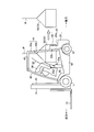
- FIG. 2 is a side view of the battery-type forklift shown in FIG. 1 in a state where the battery is loaded and unloaded.
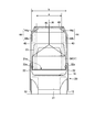
- FIG. 3 is a rear view of the battery-type forklift shown in FIG. 1 in a state where the battery is lifted.
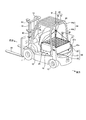
- FIG. 4 is a perspective view of the battery-type forklift shown in FIG. 1 as viewed from the rear.
- FIG. 5 is a perspective view of the battery-type forklift shown in FIG. 1 as seen from the rear, in which the battery hood is tilted and the battery is exposed.
- FIG. 6 is a perspective view of the battery-type forklift shown in FIG. FIG.
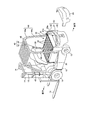
- FIG. 7 is a perspective view of the battery-type forklift shown in FIG. 1 as seen from the rear when the battery is taken out from the rear of the vehicle body.
- FIG. 8 is a rear view of a battery-type forklift that is Embodiment 2 of the present invention.
- FIG. 9 is a rear view of a battery-type forklift that is Embodiment 3 of the present invention.
- FIG. 1, FIG. 2 and FIG. 4 show a battery-type forklift that is Embodiment 1 of the present invention.
- the battery-type forklift illustrated here includes front wheels 11 at the front end corners of the vehicle body 10 and rear wheels 12 at the rear end corners of the vehicle body 10, respectively, and is driven by an electric motor (not shown). The vehicle travels using the front wheels 11 as drive wheels.
- a fork 13 for loading and unloading luggage is provided in the front part of the vehicle body 10.
- the fork 13 is supported by a mast 14 provided along the vertical direction, and can be moved up and down along the mast 14 by driving a mast cylinder 15 provided between the fork 13 and the mast 14.
- the mast 14 is attached to the vehicle body 10 so as to be rotatable about a horizontal axis along the left-right direction at the lower end portion thereof, and a tilt cylinder (not shown) is provided between the mast 14 and the vehicle body 10. It is possible to take a forward leaning posture or a backward leaning posture with respect to the vehicle body 10 by driving a tilt cylinder (not shown).
- a counterweight 20 is provided at the rear end of the vehicle body 10.
- the counterweight 20 is a metal weight for balancing when a load is supported by the fork 13, and is disposed in a part of the vehicle body 10 that extends from the part above the rear wheel 12 to the rear end.
- the counterweight 20 is formed so as to have a concave portion opened in the front-rear direction on the upper surface.
- a pair of columnar members 22 project upward from both sides of the weight main body 21 having a flat upper surface, whereby the counterweight 20 having a recess on the upper surface is configured.
- the columnar members 22 are convex portions having guide surfaces 22a that protrude upward from the portions facing each other on both sides of the weight main body 21 and toward the front of the vehicle body 10 and are parallel to each other along the front-rear direction of the vehicle body 10. Yes, it is molded integrally with the weight body 21. 4 and 5 is a resin weight cover that covers the rear surface of the counterweight 20.
- a battery 30 serving as a power source is mounted at the center of the vehicle body 10.
- the battery 30 is configured by accommodating a large number of battery cells 32 in a battery case 31 having a rectangular parallelepiped shape with an upper surface opened.
- the battery case 31 has a dimension along the left-right direction of the vehicle body 10 set slightly smaller than the distance between the guide surfaces 22 a formed on the columnar member 22. It is possible to pass between each other.
- the battery 30 is a battery mounting that is set forward of the front surface of the weight main body 21 and lower than the upper surface 21a of the weight main body 21 in the vehicle body 10. It is mounted on the surface 16 (FIG. 7).
- the position of the battery mounting surface 16 is set so that the rear end upper part of the battery 30 is interposed between the columnar members 22 and overlaps the counterweight 20. It is.
- a battery hood 33 is disposed above the battery 30 mounted on the battery mounting surface 16, and a driver seat 34 is disposed on the upper surface of the battery hood 33.
- the battery hood 33 is large enough to cover the upper surface of the battery case 31, and its front end edge tilts toward the support bracket 35 of the vehicle body 10 via the support shaft 33 a along the left-right direction of the vehicle body 10. It is supported as possible.
- the horizontal position that covers the upper side of the battery 30 and the rear edge of the battery hood 33 jump upward as shown in FIG. It is possible to move it to a forward tilt position where the upper area of the battery 30 is opened.
- the battery hood 33 When the battery hood 33 is moved to the forward tilt position, as shown in FIGS. 2 and 6, the battery hood 33 and the battery case 31 do not interfere with each other, and the bottom surface of the battery case 31 is not caused.
- the battery 30 can be lifted to a height position (hereinafter referred to as “battery transfer position”) slightly above the upper surface 21a of the weight body 21.
- the support bracket 35 that supports the battery hood 33 is erected upward from a portion located at the front end of the battery mounting surface 16.
- Cushioning material 35a is provided on the surface located at.
- the cushion material 35a is formed in a rectangular parallelepiped shape with a material having high elasticity such as rubber, and is pasted so that the vertical direction is the longitudinal direction.
- the cushion material 35a contacts the upper front portion of the battery case 31 when the battery 30 is mounted on the battery mounting surface 16, and also when the battery 30 is lifted to the battery transfer position. It is arranged so that the vertical direction is long so that it can come into contact with the front surface.
- a top plate 40 is provided in the upper region of the vehicle body 10 as shown in FIGS.
- the top plate 40 is configured by disposing a plurality of crosspieces 42 on a substantially rectangular frame 41 having a size covering the upper area of the driver seat 34, and has a dimension along the left-right direction of the vehicle body 10. Is smaller than the vehicle body 10.
- the top plate 40 is attached to the vehicle body 10 via a pair of front stays 43 and a pair of rear stays 44.
- the front stay 43 extends so as to incline downward from the front end corner of the top plate 40, and each lower end is fixed to the front end of the vehicle body 10. It is.
- the mutual interval (a in FIG. 3) of the front stays 43 is substantially the same over the entire length.
- the rear stay 44 gradually extends upward from the upper end portion of the stay main body portion 44b and the stay main body portion 44b extending upward along the substantially vertical direction so as to be parallel to each other from both sides of the rear portion of the vehicle body 10.
- an expansion portion 44a connected to the rear end corner portion of the top plate 40 is provided. The mutual interval (b in FIG.
- the stay main body portions 44b arranged in parallel to each other in the rear stay 44 is larger than the lateral width of the concave portion of the counterweight 20, that is, the guide surface 22a provided on the columnar member 22 It is configured so as to be larger than the mutual interval and not overlap with the mutual interval of the columnar members 22 when viewed from the rear of the vehicle body 10, and allows the battery case 31 and the battery hood 33 to pass therethrough (passage of the battery). region).
- the joining position of the stay main body 44b and the expanding portion 44a is such that the battery hood 33 in the horizontal position does not interfere with the rear stay 44 even when the battery hood 33 is moved forward, and the battery 30 is disposed at the battery transfer position.
- the position is set as high as possible so as not to interfere with the battery case 31.
- the stay main body 44b is fixed to the vehicle body 10 at a position ahead of the front end surface of the counterweight 20 (the front end surface 22b of the columnar member).
- the top plate 40 has slits 45 formed therein.
- the slit 45 is formed forward from the rear end of the top plate 40 along the front-rear direction of the vehicle body 10, and is provided so that the front end portion is positioned forward from the midpoint of the front-rear dimension of the battery 30. .
- the battery-type forklift constructed as described above is used for cargo handling work in a state where the battery 30 mounted on the battery mounting surface 16 is covered by the battery hood 33 and the rear surface of the counterweight 20 is covered by the weight cover 23. That is, a desired cargo handling operation can be performed by traveling through the front wheels 11 and the rear wheels 12 by an electric motor (not shown) and lifting and lowering the forks 13 appropriately by an operation of an operator seated on the driver seat 34. It becomes possible.
- a part of the battery 30 is located behind the rear stay 44 that supports the top plate 40 and is mounted on the vehicle body 10 so as to overlap the counterweight 20. Therefore, the weight of the battery 30 effectively functions as a balance weight, and the vehicle body 10 can be configured with the weight of the counterweight 20 itself greatly reduced. Thereby, the weight of the vehicle body 10 can be reduced and the power consumption of the battery 30 can be reduced.
- the battery 30 is mounted at a position above the rear wheel 12, a large dimension along the left-right direction of the battery 30 can be secured. Accordingly, even when the battery 30 having the same weight is mounted, the size along the front-rear direction of the battery 30 is reduced, and the battery 30 can be disposed further rearward of the vehicle body 10 as a balance weight. Can be used more effectively.
- a recess is formed on the upper surface of the counterweight 20 so that the battery case 31 can pass in the front-rear direction, and the rear stay 44 that supports the top plate 40 is formed to have a dimension that allows the battery case 31 to pass therethrough.
- the top plate 40 is formed with a slit 45 extending along the front-rear direction and opening at the rear end. Therefore, as shown in FIG. 5, the weight cover 23 is removed, and the battery hood 33 is moved to the forward tilt position. When the battery hood 33 is lifted by the wire W from this state as shown in FIG. As shown in FIG. 7, if the battery 30 is translated rearward as it is, the battery 30 can be taken out from the rear of the vehicle body 10 and lowered. When the battery 30 is mounted on the vehicle body 10, the reverse operation may be performed.
- the rear stay 44 disposed on the side of the vehicle body 10 does not get in the way, and an incidental operation such as attaching and detaching the rear stay 44 does not occur. There is no possibility that the workability when loading and unloading the battery 30 is impaired.
- the interval between the stay main body portions 44b arranged in parallel with each other in the rear stay 44 is slightly larger than the interval between the guide surfaces 22a provided on the columnar member 22, and the columnar member as viewed from the rear of the vehicle body 10. 22, the stay body 44 b of the rear stay 44 is fixed to the vehicle body 10 at a position in front of the front end of the counterweight 20. There is no risk of damaging the rear stay 44 when loading and unloading.
- the guide surfaces 22a formed on the columnar members 22 move the battery 30 in the front-rear direction of the vehicle body 10. As a guide. Therefore, there is no possibility that the moving battery 30 will swing and collide with other parts, or that both may be damaged.
- the support bracket 35 that supports the battery hood 33 is provided with a cushioning material 35a, even if the battery case 31 collides with the support bracket 35 due to the momentum when the battery 30 is mounted, both of them are seriously damaged. There is no fear of coming.
- the battery 30 after the battery 30 is lifted at the mounting position of the vehicle body 10, the battery 30 can be removed from the rear side of the vehicle body 10 by passing over the counterweight 20.
- the unloading work can be easily performed.
- the widened portion 44a protruding linearly toward the side so as to gradually move away from the upper end of the rear stay 44 downward is provided. Is not limited to this.
- the widened portion 144a having a curved shape is provided so that the upper end portions of the rear stay 144 gradually approach each other upward.
- the stay main body 144b of the rear stay 144 restricts these. No incidental work such as attaching and detaching the rear stay 144 occurs, so that workability when loading and unloading the battery 30 is not impaired.
- an expanded portion 244 a that is bent so as to be close to each other is provided at the upper end portion of the rear stay 244.
- the stay main body portion 244b of the rear stay 244 restricts these. No incidental work such as attaching and detaching the rear stay 244 occurs, so that workability when loading and unloading the battery 30 is not impaired.
- Embodiment 2 and Embodiment 3 about the structure similar to Embodiment 1, the same code
- the battery 30 in which the battery case 31 accommodates a large number of battery cells 32 is illustrated, but the configuration of the battery is not limited to this.
Landscapes
- Engineering & Computer Science (AREA)
- Transportation (AREA)
- Structural Engineering (AREA)
- Mechanical Engineering (AREA)
- Chemical & Material Sciences (AREA)
- Combustion & Propulsion (AREA)
- Civil Engineering (AREA)
- Life Sciences & Earth Sciences (AREA)
- Geology (AREA)
- Forklifts And Lifting Vehicles (AREA)
Abstract
Description
12 後輪
13 フォーク
16 バッテリ載置面
20 カウンタウエイト
21 ウエイト本体
21a 上面
22 柱状部材
22a ガイド面
30 バッテリ
33 バッテリフード
34 運転席用シート
40 天板
44,144,244 リヤステー
45 スリット
Claims (9)
- 車体の前方部に配設したフォークと、前記車体の後方部に配設したカウンタウエイトとを備え、前記車体に搭載したバッテリの電力によって走行するバッテリ式フォークリフトにおいて、
前記カウンタウエイトの上面に前後方向に開放した凹部を形成し、
後輪よりも上方となる位置に、少なくとも前記バッテリの一部が前記カウンタウエイトに重なる状態で前記車体にバッテリを搭載するとともに、
前記バッテリが、前記カウンタウエイトの凹部を通して前記車体の後方に向けて取出可能としたことを特徴とするバッテリ式フォークリフト。 - 前記車体の後方部両側から上方に延びた一対のリヤステーを介して運転席の上方域を覆う位置に支持させた天板を備え、
前記天板には、前記車体の前後方向に沿い、後端に開口するスリットを形成したことを特徴とする請求項1に記載のバッテリ式フォークリフト。 - 車体後方から見て、前記一対のリヤステーの少なくとも下方側が互いに平行となるように、かつ鉛直方向に沿うように形成されることにより、前記バッテリを取り外す際のバッテリの通過領域が形成されることを特徴とする請求項2に記載のバッテリ式フォークリフト。
- 前記リヤステーは、前記バッテリの通過領域よりも上方となる部位において互いに近接するように延在方向を変更した後、前記天板の後端隅部に連結したことを特徴とする請求項3に記載のバッテリ式フォークリフト。
- 前記リヤステーは、上端部が互いに近接するように屈曲したことを特徴とする請求項4に記載のバッテリ式フォークリフト。
- 前記リヤステーは、上端部が互いに近接するように湾曲したことを特徴とする請求項4に記載のバッテリ式フォークリフト。
- 車体後方から見て、前記一対のリヤステーは、少なくとも下方側が互いに平行となるように、かつ鉛直方向に沿うように形成される部位の間隔が前記カウンタウエイトの凹部の横巾よりも大きく、かつ車体後方から見て、カウンタウエイトの凹部と重ならないように構成されることを特徴とする請求項2に記載のバッテリ式フォークリフト。
- 前記一対のリヤステーは、前記カウンタウエイトの前端面よりも前方で前記車体に固定されることを特徴とする請求項7に記載のバッテリ式フォークリフト。
- 前記バッテリの上方部に前記車体の前方に向けて傾倒可能にバッテリフードを設けるとともに、前記バッテリフードの上面に運転席用シートを配設し、
前記バッテリフードを前方に傾倒する際に、前記バッテリフード及び前記運転席用シートが前記一対のリヤステーと干渉しないように、前記リヤステーの間に前記バッテリの通過領域を構成したことを特徴とする請求項5に記載のバッテリ式フォークリフト。
Priority Applications (4)
| Application Number | Priority Date | Filing Date | Title |
|---|---|---|---|
| US13/816,415 US8789636B2 (en) | 2011-04-08 | 2012-03-13 | Battery-powered forklift |
| CN201280002405.8A CN103068717B (zh) | 2011-04-08 | 2012-03-13 | 电池式叉车 |
| DE112012000063T DE112012000063T5 (de) | 2011-04-08 | 2012-03-13 | Batterieangetriebener Gabelstapler |
| JP2012548264A JP5162053B2 (ja) | 2011-04-08 | 2012-03-13 | バッテリ式フォークリフト |
Applications Claiming Priority (2)
| Application Number | Priority Date | Filing Date | Title |
|---|---|---|---|
| JP2011086787 | 2011-04-08 | ||
| JP2011-086787 | 2011-04-08 |
Publications (1)
| Publication Number | Publication Date |
|---|---|
| WO2012137582A1 true WO2012137582A1 (ja) | 2012-10-11 |
Family
ID=46968986
Family Applications (1)
| Application Number | Title | Priority Date | Filing Date |
|---|---|---|---|
| PCT/JP2012/056446 Ceased WO2012137582A1 (ja) | 2011-04-08 | 2012-03-13 | バッテリ式フォークリフト |
Country Status (5)
| Country | Link |
|---|---|
| US (1) | US8789636B2 (ja) |
| JP (1) | JP5162053B2 (ja) |
| CN (1) | CN103068717B (ja) |
| DE (1) | DE112012000063T5 (ja) |
| WO (1) | WO2012137582A1 (ja) |
Cited By (3)
| Publication number | Priority date | Publication date | Assignee | Title |
|---|---|---|---|---|
| JP5498623B1 (ja) * | 2013-01-08 | 2014-05-21 | 株式会社小松製作所 | 作業機械用バッテリケース、作業機械用バッテリユニット、バッテリ式作業機械及びバッテリ式フォークリフト |
| FR3018797A1 (fr) * | 2014-03-19 | 2015-09-25 | Geismar Ancien Ets L | Machine de levage de poids, comprenant un dispositif de fleche de grue et un dispositif de contrepoids |
| CN105051969A (zh) * | 2013-03-29 | 2015-11-11 | 株式会社丰田自动织机 | 电池组 |
Families Citing this family (8)
| Publication number | Priority date | Publication date | Assignee | Title |
|---|---|---|---|---|
| CN102906003B (zh) * | 2011-04-08 | 2014-05-21 | 株式会社小松制作所 | 蓄电池式叉车 |
| JP5692539B2 (ja) * | 2012-09-18 | 2015-04-01 | 株式会社豊田自動織機 | 産業車両 |
| JP5831504B2 (ja) * | 2013-07-03 | 2015-12-09 | 株式会社豊田自動織機 | 産業車両 |
| WO2017162292A1 (en) * | 2016-03-24 | 2017-09-28 | Volvo Truck Corporation | A vehicle cab body for a vehicle |
| JP6521340B1 (ja) * | 2018-04-10 | 2019-05-29 | 三菱ロジスネクスト株式会社 | カウンタバランス型のバッテリー式フォークリフト |
| JP6687312B1 (ja) * | 2019-03-01 | 2020-04-22 | 三菱ロジスネクスト株式会社 | 荷役車両 |
| CN110600645A (zh) * | 2019-08-30 | 2019-12-20 | 北斗航天汽车(北京)有限公司 | 一种电动叉车的套装式电池箱及电动叉车 |
| JP7502458B2 (ja) * | 2020-10-30 | 2024-06-18 | 本田技研工業株式会社 | 作業車 |
Citations (5)
| Publication number | Priority date | Publication date | Assignee | Title |
|---|---|---|---|---|
| JP2001316091A (ja) * | 2000-05-12 | 2001-11-13 | Nippon Yusoki Co Ltd | バッテリフォークリフト |
| JP2002308582A (ja) * | 2001-04-18 | 2002-10-23 | Mitsubishi Heavy Ind Ltd | バッテリ車におけるバッテリの収納構造 |
| JP2003002592A (ja) * | 2001-06-15 | 2003-01-08 | Toyota Industries Corp | 産業車両用のフードの開閉構造 |
| JP2003118990A (ja) * | 2001-10-12 | 2003-04-23 | Komatsu Forklift Co Ltd | 産業車両における燃料ガス用カウンターウエイト装置 |
| JP3838419B2 (ja) * | 2001-08-22 | 2006-10-25 | 日本輸送機株式会社 | カウンタバランス型バッテリフォークリフト |
Family Cites Families (13)
| Publication number | Priority date | Publication date | Assignee | Title |
|---|---|---|---|---|
| JPS5027103Y1 (ja) * | 1970-08-07 | 1975-08-12 | ||
| JPS5313761Y2 (ja) | 1973-07-13 | 1978-04-13 | ||
| US4026378A (en) | 1975-11-28 | 1977-05-31 | Clark Equipment Company | Electric lift truck body construction |
| JPS581089U (ja) * | 1981-06-25 | 1983-01-06 | 日産自動車株式会社 | バツテリ式フオ−クリフトにおけるバツテリ交換装置 |
| WO2000064800A1 (en) * | 1999-04-26 | 2000-11-02 | Tcm Corporation | Fork lift with laterally moving system |
| JP3877122B2 (ja) * | 2000-02-03 | 2007-02-07 | 日本輸送機株式会社 | フォークリフト |
| JP2001302192A (ja) * | 2000-04-20 | 2001-10-31 | Nippon Yusoki Co Ltd | フォークリフト |
| JP3768426B2 (ja) * | 2001-10-17 | 2006-04-19 | 小松フォークリフト株式会社 | バッテリ式フォークリフトトラックのバッテリ交換装置 |
| JP2003182990A (ja) * | 2001-12-21 | 2003-07-03 | Komatsu Forklift Co Ltd | バッテリ式フォークリフトトラック |
| JP2005041656A (ja) * | 2003-07-23 | 2005-02-17 | Tcm Corp | 電動車両用バッテリボックスの移動案内装置 |
| GB2454067B (en) | 2007-10-04 | 2012-05-16 | Linde Material Handling Gmbh | Fork-lift truck with an electric battery drive system |
| DE102008004653A1 (de) | 2007-10-04 | 2009-04-09 | Linde Material Handling Gmbh | Gabelstapler mit einem batterie-elektrischen Antriebssystem |
| JP2009274651A (ja) * | 2008-05-16 | 2009-11-26 | Toyota Industries Corp | ハイブリッド産業車両 |
-
2012
- 2012-03-13 WO PCT/JP2012/056446 patent/WO2012137582A1/ja not_active Ceased
- 2012-03-13 US US13/816,415 patent/US8789636B2/en not_active Expired - Fee Related
- 2012-03-13 DE DE112012000063T patent/DE112012000063T5/de not_active Withdrawn
- 2012-03-13 JP JP2012548264A patent/JP5162053B2/ja active Active
- 2012-03-13 CN CN201280002405.8A patent/CN103068717B/zh not_active Expired - Fee Related
Patent Citations (5)
| Publication number | Priority date | Publication date | Assignee | Title |
|---|---|---|---|---|
| JP2001316091A (ja) * | 2000-05-12 | 2001-11-13 | Nippon Yusoki Co Ltd | バッテリフォークリフト |
| JP2002308582A (ja) * | 2001-04-18 | 2002-10-23 | Mitsubishi Heavy Ind Ltd | バッテリ車におけるバッテリの収納構造 |
| JP2003002592A (ja) * | 2001-06-15 | 2003-01-08 | Toyota Industries Corp | 産業車両用のフードの開閉構造 |
| JP3838419B2 (ja) * | 2001-08-22 | 2006-10-25 | 日本輸送機株式会社 | カウンタバランス型バッテリフォークリフト |
| JP2003118990A (ja) * | 2001-10-12 | 2003-04-23 | Komatsu Forklift Co Ltd | 産業車両における燃料ガス用カウンターウエイト装置 |
Cited By (9)
| Publication number | Priority date | Publication date | Assignee | Title |
|---|---|---|---|---|
| JP5498623B1 (ja) * | 2013-01-08 | 2014-05-21 | 株式会社小松製作所 | 作業機械用バッテリケース、作業機械用バッテリユニット、バッテリ式作業機械及びバッテリ式フォークリフト |
| WO2014109002A1 (ja) * | 2013-01-08 | 2014-07-17 | 株式会社小松製作所 | 作業機械用バッテリケース、作業機械用バッテリユニット、バッテリ式作業機械及びバッテリ式フォークリフト |
| CN104040754A (zh) * | 2013-01-08 | 2014-09-10 | 株式会社小松制作所 | 作业机械用蓄电池壳体、作业机械用蓄电池单元、蓄电池式作业机械及蓄电池式叉车 |
| CN104040754B (zh) * | 2013-01-08 | 2016-02-10 | 株式会社小松制作所 | 作业机械用蓄电池壳体、作业机械用蓄电池单元、蓄电池式作业机械及蓄电池式叉车 |
| US9583749B2 (en) | 2013-01-08 | 2017-02-28 | Komatsu Ltd. | Work equipment battery case and battery unit |
| CN105051969A (zh) * | 2013-03-29 | 2015-11-11 | 株式会社丰田自动织机 | 电池组 |
| EP2980914A4 (en) * | 2013-03-29 | 2016-09-28 | Toyota Jidoshokki Kk | BATTERY PACK |
| US9917338B2 (en) | 2013-03-29 | 2018-03-13 | Kabushiki Kaisha Toyota Jidoshokki | Battery pack |
| FR3018797A1 (fr) * | 2014-03-19 | 2015-09-25 | Geismar Ancien Ets L | Machine de levage de poids, comprenant un dispositif de fleche de grue et un dispositif de contrepoids |
Also Published As
| Publication number | Publication date |
|---|---|
| JP5162053B2 (ja) | 2013-03-13 |
| CN103068717B (zh) | 2015-08-05 |
| DE112012000063T5 (de) | 2013-08-22 |
| CN103068717A (zh) | 2013-04-24 |
| JPWO2012137582A1 (ja) | 2014-07-28 |
| US8789636B2 (en) | 2014-07-29 |
| US20140020967A1 (en) | 2014-01-23 |
Similar Documents
| Publication | Publication Date | Title |
|---|---|---|
| JP5162053B2 (ja) | バッテリ式フォークリフト | |
| JP5498623B1 (ja) | 作業機械用バッテリケース、作業機械用バッテリユニット、バッテリ式作業機械及びバッテリ式フォークリフト | |
| JP4259694B2 (ja) | 車両用バッテリの搭載構造 | |
| EP2933859B1 (en) | Battery pack and industrial vehicle | |
| JP5983058B2 (ja) | 電気自動車のバッテリパック搭載構造 | |
| JP7025226B2 (ja) | 旋回フレーム及び建設機械 | |
| CN104039680B (zh) | 蓄电池式叉车 | |
| CN104041203B (zh) | 蓄电池式作业机械以及蓄电池式叉车 | |
| JP2013067202A (ja) | 車両用バッテリ搭載構造 | |
| JP2000226194A (ja) | バッテリ式産業車両のフレーム構造 | |
| JP5090582B1 (ja) | バッテリ式フォークリフト | |
| CN112550479B (zh) | 电动车辆的车身 | |
| JP2019114469A (ja) | 燃料電池車両 | |
| CN104039681A (zh) | 蓄电池式叉车 | |
| JP2013239261A (ja) | 荷役搬送用産業車両 | |
| JP5915367B2 (ja) | 荷役搬送用産業車両 | |
| JP6493183B2 (ja) | 車両構造 | |
| EP4067289B1 (en) | Industrial truck with improved structure for supporting the battery | |
| JP2011011619A (ja) | 燃料電池駆動車両 | |
| JP5950456B2 (ja) | 車両の車体後部構造 | |
| JP2022159583A (ja) | 車両用電池モジュール搭載ケース体 | |
| EP4234476B1 (en) | Electrically-powered industrial truck | |
| JP2008074537A (ja) | 移動リフター | |
| JP2003238083A (ja) | バッテリ式フォークリフト | |
| JP2009208522A (ja) | バッテリ搭載構造 |
Legal Events
| Date | Code | Title | Description |
|---|---|---|---|
| WWE | Wipo information: entry into national phase |
Ref document number: 201280002405.8 Country of ref document: CN |
|
| ENP | Entry into the national phase |
Ref document number: 2012548264 Country of ref document: JP Kind code of ref document: A |
|
| 121 | Ep: the epo has been informed by wipo that ep was designated in this application |
Ref document number: 12767504 Country of ref document: EP Kind code of ref document: A1 |
|
| WWE | Wipo information: entry into national phase |
Ref document number: 13816415 Country of ref document: US |
|
| WWE | Wipo information: entry into national phase |
Ref document number: 112012000063 Country of ref document: DE Ref document number: 1120120000633 Country of ref document: DE |
|
| 122 | Ep: pct application non-entry in european phase |
Ref document number: 12767504 Country of ref document: EP Kind code of ref document: A1 |