WO2012137558A1 - 車両用ドア装置 - Google Patents
車両用ドア装置 Download PDFInfo
- Publication number
- WO2012137558A1 WO2012137558A1 PCT/JP2012/054878 JP2012054878W WO2012137558A1 WO 2012137558 A1 WO2012137558 A1 WO 2012137558A1 JP 2012054878 W JP2012054878 W JP 2012054878W WO 2012137558 A1 WO2012137558 A1 WO 2012137558A1
- Authority
- WO
- WIPO (PCT)
- Prior art keywords
- door
- holding member
- handle device
- cable
- door panel
- Prior art date
- Legal status (The legal status is an assumption and is not a legal conclusion. Google has not performed a legal analysis and makes no representation as to the accuracy of the status listed.)
- Ceased
Links
Images




Classifications
-
- E—FIXED CONSTRUCTIONS
- E05—LOCKS; KEYS; WINDOW OR DOOR FITTINGS; SAFES
- E05B—LOCKS; ACCESSORIES THEREFOR; HANDCUFFS
- E05B85/00—Details of vehicle locks not provided for in groups E05B77/00 - E05B83/00
- E05B85/10—Handles
- E05B85/12—Inner door handles
-
- E—FIXED CONSTRUCTIONS
- E05—LOCKS; KEYS; WINDOW OR DOOR FITTINGS; SAFES
- E05B—LOCKS; ACCESSORIES THEREFOR; HANDCUFFS
- E05B79/00—Mounting or connecting vehicle locks or parts thereof
- E05B79/10—Connections between movable lock parts
- E05B79/20—Connections between movable lock parts using flexible connections, e.g. Bowden cables
-
- E—FIXED CONSTRUCTIONS
- E05—LOCKS; KEYS; WINDOW OR DOOR FITTINGS; SAFES
- E05B—LOCKS; ACCESSORIES THEREFOR; HANDCUFFS
- E05B53/00—Operation or control of locks by mechanical transmissions, e.g. from a distance
- E05B53/003—Operation or control of locks by mechanical transmissions, e.g. from a distance flexible
-
- E—FIXED CONSTRUCTIONS
- E05—LOCKS; KEYS; WINDOW OR DOOR FITTINGS; SAFES
- E05B—LOCKS; ACCESSORIES THEREFOR; HANDCUFFS
- E05B79/00—Mounting or connecting vehicle locks or parts thereof
- E05B79/02—Mounting of vehicle locks or parts thereof
- E05B79/06—Mounting of handles, e.g. to the wing or to the lock
-
- E—FIXED CONSTRUCTIONS
- E05—LOCKS; KEYS; WINDOW OR DOOR FITTINGS; SAFES
- E05B—LOCKS; ACCESSORIES THEREFOR; HANDCUFFS
- E05B79/00—Mounting or connecting vehicle locks or parts thereof
- E05B79/10—Connections between movable lock parts
- E05B79/22—Operative connections between handles, sill buttons or lock knobs and the lock unit
-
- E—FIXED CONSTRUCTIONS
- E05—LOCKS; KEYS; WINDOW OR DOOR FITTINGS; SAFES
- E05B—LOCKS; ACCESSORIES THEREFOR; HANDCUFFS
- E05B85/00—Details of vehicle locks not provided for in groups E05B77/00 - E05B83/00
- E05B85/10—Handles
- E05B85/12—Inner door handles
- E05B85/13—Inner door handles with a locking knob forming part of the inside door handle unit
Definitions
- the present invention covers a door opening portion of a vehicle body with a door body that can be opened and closed, a handle device is attached to a door panel of the door body, and a lock unit for engaging the door body with the vehicle body is provided.
- the present invention relates to a vehicle door device provided with a cable connecting the two.
- a vehicle door device that includes a door body that covers a door opening portion of a vehicle body so as to be openable and closable and a handle device that is attached to a door panel of the door body is known, for example, as disclosed in Patent Document 1. Yes.
- the handle device includes an inner handle for releasing the lock unit, a cable for transmitting an operation force of the inner handle to the lock unit, and a handle base for incorporating these inner handle and the cable.
- the handle base has a handle base attaching portion for attaching the handle base to the door panel, and a cable clamp (cable holding member) for supporting the cable.
- the handle base since the handle base has the cable clamp (cable holding member), the cable can be reliably supported.
- Patent Document 1 discloses a vehicle door device in which a cable clamp (cable holding member) is rotatably attached to a handle base of an inner handle attached to the inside of a door.
- the cable clamp is fixed to the handle base by rotating the cable clamp and engaging the cable after the operator sets the cable in the U-shaped groove provided on the handle base when assembling the door. To do.
- the present invention when a handle device is attached to a door panel, it is possible to determine whether or not the cable holding member is in the engaged position, and it is possible to omit the confirmation work of whether or not the cable holding member is in the engaged position. It is an object to provide an apparatus.
- a door device for a vehicle the door body covering the door opening (14) of the vehicle body so as to be opened and closed, the handle device attached to the door panel of the door body, and the door body.
- a vehicle door device in which an interference portion for avoiding interference with the cable holding member located at an engagement position is provided on the door panel. It is.
- the cable holding member projects closer to the door panel side than the door panel side end portion of the handle device adjacent to the interference portion of the door panel when the cable holding member is located at the non-engagement position. And when it is located in the engagement position, it has a protruding portion that is housed inside the handle device from the door panel side end, and when the cable holding member is in the non-engagement position, The protruding portion interferes with the interference portion.
- the door panel side end abuts against the interference portion.
- the handle device includes an attachment portion to which the cable holding member is attached, and the end portion on the door panel side is provided in the vicinity of the attachment portion.
- the cable holding member is rotatably supported by the attachment portion via a rotation shaft, and a perpendicular line is formed from the center of the rotation shaft toward the interference portion.
- the door panel side end is provided within a range through which the perpendicular passes.
- the door panel side end portion is a contact rib protruding toward the interference portion side.
- the door panel side end portion is preferably provided on one end side in the longitudinal direction of the handle device.
- the handle device includes a handle device attaching portion for attaching the handle device to the door panel, and the handle device attaching portion is provided on the other end side in the longitudinal direction of the handle device. It has been.
- the cable holding member when the cable holding member is located at the non-engagement position, it projects to the door panel side from the door panel side end portion of the handle device that is close to the interference portion of the door panel, and is located at the engagement position.
- the protruding portion interferes with the interference portion when the cable holding member is in the disengaged position. The operation of confirming whether the holding member is in the engagement position can be omitted, and the workability of assembling the cable holding member can be improved.
- the door panel side end portion is brought into contact with the interference portion, so that the handle device can be prevented from rattling. Furthermore, since the interference portion is used to prevent rattling, the structure of the handle device can be simplified.
- the handle device is provided with an attachment portion to which the cable holding member is attached, and the door panel side end portion is provided in the vicinity of the attachment portion. Since the attachment portion to which the cable holding member is attached is in contact with the interference portion, the attachment rigidity of the cable holding member is increased, and the fluttering of the cable can be effectively suppressed.
- the door panel side end portion is a contact rib protruding to the interference portion side, the rigidity of the mounting portion can be further increased.
- one end side of the handle device is supported by the interference portion, and the handle device mounting portion is efficiently arranged by providing the handle device mounting portion on the other end side in the longitudinal direction of the handle device.
- the rattling of the handle device can be more effectively suppressed.
- FIG. 1 is a side view of a vehicle in which a vehicle door device according to an embodiment of the present invention is employed. It is the perspective view which looked at the vehicle door shown by FIG. 1 from the vehicle interior side.
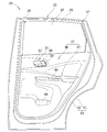
- FIG. 3 is a side view of the vehicle door handle device and the door panel shown in FIG. 2. It is the side view which showed the door panel shown by FIG.
- FIG. 4 is a perspective view of the handle device shown in FIG. 3.
- FIG. 6 is a perspective view of the handle device shown in FIG. 5 as viewed from the rear side of the passenger compartment. It is the perspective view which showed the cable holding member before the cable attachment shown by FIG. It is the perspective view which showed the state before rotation of the cable holding member shown by FIG. FIG.
- FIG. 8 is a perspective view illustrating a state in which a cable is attached by rotating the cable holding member illustrated in FIG. 7.
- FIG. 10 is a sectional view taken along line 10-10 in FIG.
- FIG. 6 is a cross-sectional view taken along line 11-11 in FIG.
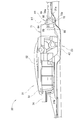
- FIG. 6 is a bottom view when the cable holding member of the handle device shown in FIG. 5 is in an engaged position.
- FIG. 6 is a bottom view when the cable holding member of the handle device shown in FIG. 5 is in a disengaged position.
- the vehicle 10 has a door opening 14 through which a passenger gets on and off the vehicle body 11.
- the vehicle door 20 is attached to the door opening 14 so as to be freely opened and closed.
- the vehicle door 20 is a rear door provided at the rear portion of the vehicle body 11, and includes a door body 21 that covers the door opening 14 so as to be freely opened and closed, and a door glass 22 that raises and lowers the door body 21.
- the door body 21 has a door panel 23 that covers the side of the vehicle body 11 on the outside of the vehicle, an outer handle 24 that opens and closes the door body 21 from the outside of the vehicle, and a door glass that is provided on the top of the door panel 23. 22, a front garnish 26 that covers the front portion of the door sash 25 from the outside of the vehicle, and a rear garnish 27 that covers the rear portion of the door sash 25 from the outside of the vehicle.
- the door body 21 is attached to the door panel 23 on the vehicle compartment 12 side, and a handle device for unlocking or locking the door main body 21 from within the vehicle compartment 12.
- a latch device 33 for engaging the door main body 21 with the striker 29 on the vehicle body 11 (door opening 14) side
- a cable (latch side cable) 35 for connecting the handle device 31 and the latch device 33
- a lock device 34 that locks the latch device 33
- a lock-side cable 36 that connects the handle device 31 and the lock device 34
- an interior member 37 that covers the vehicle compartment 12 side of the door panel 23.
- the door panel 23 is provided between the outer panel 41 that is a vehicle body exterior, the inner panel 42 provided on the outer panel 41 on the vehicle compartment 12 side, and the outer panel 41 and the inner panel 42.
- the impact beam 43 is increased.
- the inner panel 42 interferes with a cable holding member (latch-side cable holding member) 58 (see FIGS. 5 and 10) located at a non-engaging position A2 (see FIG. 13), which will be described later, and an engaging position A1, which will be described later.
- An interference part 44 (see FIGS. 4 and 11) is provided to avoid interference with the cable holding member 58 located at (see FIG. 12).
- the latch device 33 and the lock device 34 are one unit configured as the lock unit 32.
- the handle device 31 includes an inner handle 52, a lock knob 56, and a decorative cover 57.
- the interior member 37 includes a door lining 46 that covers the inner panel 42 of the door panel 23, and an armrest 47 that is provided at a substantially central height of the door lining 46 and extending in the longitudinal direction of the vehicle body.
- the door lining 46 is formed with a storage portion 48 for storing articles.
- the armrest 47 is provided with a clue part (pull pocket) 49 for opening and closing the door body 21 and a door glass operation switch (not shown) for raising and lowering the door glass 22.
- the handle device (inside door handle device) 31 swings via a handle base 51 attached to the inner panel 42 and a support shaft 77 (FIG. 11) of the handle base 51.
- the cable (latch-side cable) 35 includes an inner cable 61 that directly connects the handle device 31 and the latch device 33 (FIG. 3), and an outer tube 62 that slidably supports the inner cable 61. It consists of.
- the outer tube 62 is formed with a fitting groove 63 to be fitted to the handle base 51 of the handle device 31 and a cylindrical portion 64 supported to the handle base 51 side of the handle device 31 on the handle device 31 side. Yes.
- the lock-side cable 36 supports an inner cable (not shown) that directly connects the handle device 31 and the lock device 34 (FIG. 3), and slidably supports the inner cable. And an outer tube 67.
- the outer tube 67 has a fitting groove (not shown) fitted to the handle base 51 of the handle device 31 on the handle device 31 side, and a cylindrical portion (not shown) supported on the handle base 51 side of the handle device 31. ) And are formed.
- the handle base 51 includes a mounting portion (latch side mounting portion) 71 in which a cable holding member (latch side cable holding member) 58 is rotatably (rotatably) engaged, and a lock.
- the attachment portion (latch side attachment portion) 71 has an engagement hole 81 in which a cable holding member (latch side cable holding member) 58 is rotatably engaged.
- the lock side mounting portion 72 has an engagement hole 82 with which the lock side cable holding member 59 is rotatably engaged.
- the handle device attachment portions 91 and 92 are portions for attaching the handle device 31 to the door panel 23.
- the handle device attaching portions 91 and 92 are provided on the other end 31b side (FIG. 11) of the handle device 31 in the longitudinal direction.
- the inner panel 42 of the door panel 23 is provided with fastening holes 93a and 93b (FIG. 4) for attaching the handle device attaching portions 91 and 92 to the inner panel 42 with clips (not shown). Yes.
- the longitudinal direction of the handle device 31 substantially coincides with the longitudinal direction of the vehicle body.
- the cable holding member (latch-side cable holding member) 58 has a base portion 84 that abuts against the attachment portion (latch-side attachment portion) 71 and a U-shape on one side of the base portion 84. Formed on the other side of the base portion 84 and a cable fitting portion 85 that holds the cable (latch side cable) 35, and is rotatably engaged with an engagement hole 81 (FIG. 10) of the mounting portion 71. And the engaging claws 87 and 87 (one not shown) formed on the rotating shaft 86 and engaged with the mounting portion 71.
- the cable holding member (latch side cable holding member) 58 is rotatably supported by the attachment portion (latch side attachment portion) 71 via a rotation shaft 86.
- the inside of the handle device 31 refers to the handle device 31 side in the vehicle inside / outside direction (direction perpendicular to the contact surface 44a of the interference portion 44) (the inner handle 52 is the vehicle compartment 12 side, and the outer handle 24 is the vehicle outside). .
- a position where the protruding portion 88 of the cable holding member 58 does not interfere with the interference portion 44 of the door panel 23 (inner panel 42) is defined as an engagement position A1.
- a position where the protruding portion 88 of the cable holding member 58 interferes with the interference portion 44 of the door panel 23 (inner panel 42) is defined as a non-engagement position A2.
- the lock-side cable holding member 59 has the same configuration as the cable holding member (latch-side cable holding member) 58, and has a base portion 94, a cable fitting portion 95, and a rotation. It comprises a shaft 96 and engaging claws 97, 97 (one not shown). The bottom of the U-shaped cable fitting portion 95 corresponds to the protruding portion 98.
- the door panel side end 73 will be described in detail with reference to FIGS.
- the door panel side end portion 73 is a part of the handle base 51 and is a substantially rectangular contact rib that is provided in the vicinity of the attachment portion (latch side attachment portion) 71 and protrudes toward the interference portion 44 side on the door panel 23 side. . Further, the door panel side end portion 73 is a portion that is brought into contact with the interference portion 44 when the handle device 31 is attached to the door panel 23. Further, the door panel side end portion 73 is provided within a range through which the perpendicular line H1 passes when the perpendicular line H1 is drawn from the center of the rotation shaft 86 toward the interference part 44.
- the door panel side end portion 73 is provided at the same position as the rotation shaft 86 in the contact direction with the interference portion 44.
- the contact direction with the interference unit 44 is a direction in which the handle device 31 is attached, and coincides with the vehicle width direction and is a direction perpendicular to the contact surface 44a of the interference unit 44.
- the door panel side end 73 is provided in the vicinity of the attachment portion (latch side attachment portion) 71.
- the door panel side end portion 73 is an end portion in the vicinity of the cable holding member (latch side cable holding member) 58 and is located inside the outermost end portion of the entire handle device 31.
- the cable holding member (latch-side cable holding member) 58 has the rotation shaft 86 attached to the attachment portion (latch-side attachment portion) 71 before the handle device 31 is attached to the inner panel 42 (FIG. 6). Is set in the engagement hole 81 (FIG. 10). In this state, the protruding portion (bottom of the U-shaped cable fitting portion 85) 88 protrudes toward the door panel 23 (FIG. 3) from the door panel contact surface 73a of the door panel side end portion (contact rib) 73. Set to That is, the cable holding member 58 is set at the non-engaging position A2 (FIG. 13).
- the latch fitting portion 78 of the handle base 51 is fitted into the fitting groove 63 of the cable (latch side cable) 35 as indicated by the arrow b1. Further, the cable holding member 58 is rotated as indicated by an arrow b2 so as to approach the cable 35 around the rotation shaft 86, and the cable (latch side cable) 35 is held by the cable holding member (latch side cable holding member) 58. Complete.
- the cable holding member 58 is displaceable between an engagement position A1 (FIG. 12) that engages with the cable 35 and a non-engagement position A2 (FIG. 13) that does not engage the cable 35. 51 is attached.
- the U-shaped cable fitting portion 85 of the cable holding member 58 is fitted to the tube portion 64 of the cable 35, and the cable holding member 58 is more handle than the door panel side end portion 73.
- the cable 31 is housed inside the device 31 and supports the cable 35 with a cable holding member 58. That is, the cable holding member 58 is set at the engagement position A1 (FIG. 12).
- the handle device 31 is attached to the inner panel 42 with the cable holding member 58 in the engagement position A1 (FIG. 12). For example, as shown in FIG. 13, in a state where the cable holding member 58 is in the non-engaging position A2, the protruding portion 88 of the cable holding member 58 hits the interference portion 44 on the door panel 23 side. Thereby, it can be found when the handle device 31 is attached that the cable holding member 58 is not in the engagement position A1.
- the protruding portion 88 interferes with the interference portion 44 only when the cable holding member 58 is in the non-engaging position A2.
- a door main body 21 that covers the door opening 14 of the vehicle body 11 so as to be openable and closable, a handle device 31 attached to the door panel 23 of the door main body 21, and the door main body 21.
- the cable 35 that couples the handle device 31 and the lock unit 32, the engagement position A ⁇ b> 1 (FIG. 12) that is engaged with the cable 35, and the cable 35 is not engaged.
- a cable holding member 58 (FIG. 9) attached to the handle device 31 so as to be displaceable to the non-engaging position A2 (FIG. 13) is provided.
- the cable holding member 58 interferes with the cable holding member 58 located at the non-engagement position A2 and is located at the engagement position A1. Since the interference part 44 for avoiding the interference with the door 58 is provided on the door panel 23, the interference part 44 can determine whether or not the cable holding member 58 is in the engagement position A1 when the handle device 31 is attached to the door panel 23. . As a result, it is possible to omit the confirmation of whether or not the cable holding member 58 is in the engagement position A1, and the workability of assembling the cable holding member 58 can be improved.
- the cable holding member 58 includes a protruding portion 88 that protrudes to the door panel 23 side from the side end portion 73 and is housed inside the handle device 31 from the door panel side end portion 73 when positioned at the engagement position A1. Since the projecting portion 88 interferes with the interference portion 44 when is in the non-engagement position A2, it is possible to omit the operation of confirming whether or not the cable holding member 58 is in the engagement position A1. The workability of assembling the member 58 can be improved.
- the door panel side end portion 73 is brought into contact with the interference portion 44, so that rattling of the handle device 31 can be prevented.
- the interference unit 44 is used to prevent rattling, the structure of the handle device 31 can be simplified.
- the vehicle door 20 includes an attachment portion 71 to which the cable holding member 58 (FIG. 10) is attached to the handle device 31, and the door panel side end portion 73 is provided in the vicinity of the attachment portion 71. Since the attachment portion 71 to which the cable holding member 58 is attached is in contact with the interference portion 44, the attachment rigidity of the cable holding member 58 is increased, and fluttering of the cable 35 can be effectively suppressed.
- the cable holding member 58 (FIG. 10) is rotatably supported by the attachment portion 71 via the rotation shaft 86 and is directed from the center of the rotation shaft 86 toward the interference portion 44.
- the door panel side end portion 73 is provided within a range through which the perpendicular line H ⁇ b> 1 passes, so that the rotation shaft 86 can be supported by contact with the interference portion 44.
- the attachment rigidity of the cable holding member 58 can be further increased.
- the door panel side end portion 73 is a substantially rectangular abutment rib that protrudes toward the interference portion 44, so that the door panel side end portion 73 becomes the interference portion 44. It can hit on a wide surface, and the rigidity of the mounting portion 71 is further increased.
- the door panel side end portion 73 is provided on the one end 31 a side in the longitudinal direction of the handle device 31, so that one end (end portion) 31 a in the longitudinal direction of the handle device 31 is connected to the interference portion 44. I can support it. As a result, the rattling of the handle device 31 can be more effectively suppressed.
- handle device attachment portions 91 and 92 for attaching the handle device 31 to the door panel 23 are provided on the other end 31 b side of the handle device 31 in the longitudinal direction.
- One end 31 a side of the handle device 31 is supported by the interference portion 44, and the handle device mounting portions 91 and 92 are efficiently provided by providing the handle device mounting portions 91 and 92 on the other end 31 b side in the longitudinal direction of the handle device 31.
- the backlash of the handle device 31 can be suppressed more effectively.
- the cable is exemplified by a cable (latch side cable) 35 for connecting the handle device 31 and the latch device 33, but is not limited thereto.
- a lock-side cable 36 that connects the handle device 31 and the lock device 34 may be used.
- the cable holding member (latch side cable holding member) 58 is attached to the attachment portion (latch side attachment portion) 71 so as to be rotatable.
- the attachment portion (latch side attachment portion) 71
- You may be made into the slide structure.
- the vehicle door according to the present invention is a rear door provided at the rear portion of the vehicle body 11, but is not limited thereto, and may be a front door.
- the handle device mounting portions 91 and 92 are fastened to the fastening holes 93a and 93b of the inner panel 42 by clips (not shown). It may not be a thing but a bolt fastening.
- the vehicle door according to the present invention is suitable for use in passenger cars such as sedans and wagons.
Landscapes
- Lock And Its Accessories (AREA)
Abstract
Description
Claims (8)
- 車両用ドア装置であって、
車体のドア開口部を開閉可能に覆うドア本体と、
前記ドア本体のドアパネルに取付けられるハンドル装置と、
前記ドア本体を前記車体に対して係合させるロックユニットと、
前記ハンドル装置と前記ロックユニットとを連結するケーブルと、
前記ケーブルに係合する係合位置と前記ケーブルと係合しない非係合位置とに変位可能に、前記ハンドル装置に取付けられるケーブル保持部材と、
を具備しており、
前記ハンドル装置が前記ドアパネルに取付けられた状態において、前記非係合位置に位置する前記ケーブル保持部材と干渉するとともに、前記係合位置に位置する前記ケーブル保持部材との干渉を回避する干渉部が、前記ドアパネルに設けられていることを特徴とする車両用ドア装置。 - 前記ケーブル保持部材は、前記非係合位置に位置するときに前記ドアパネルの前記干渉部に近接する前記ハンドル装置のドアパネル側端部よりもドアパネル側に突出するとともに、前記係合位置に位置するときは前記ドアパネル側端部よりも前記ハンドル装置の内方に収納される突出部を備えており、前記ケーブル保持部材が前記非係合位置にあるときに、前記突出部が前記干渉部と干渉する、請求項1に記載の車両用ドア装置。
- 前記ハンドル装置が、前記ドアパネルに取付けられた際に、前記ドアパネル側端部は前記干渉部に当接する、請求項2に記載の車両用ドア装置。
- 前記ハンドル装置は、前記ケーブル保持部材が取付けられる取付部を備え、
前記ドアパネル側端部は、前記取付部の近傍位置に設けられている、請求項2に記載の車両用ドア装置。 - 前記ケーブル保持部材は、前記取付部に回動軸を介して回動可能に支持されており、前記回動軸の中心から前記干渉部に向かって垂線を引くときに、前記ドアパネル側端部は、前記垂線が通過する範囲内に設けられている、請求項4に記載の車両用ドア装置。
- 前記ドアパネル側端部は、前記干渉部側に向けて突出する当接リブである、請求項4又は請求項5記載の車両用ドア装置。
- 前記ドアパネル側端部は、前記ハンドル装置の長手方向の一端側に設けられている、請求項2に記載の車両用ドア装置。
- 前記ハンドル装置は、該ハンドル装置を前記ドアパネルに取付けるハンドル装置取付部を備えており、前記ハンドル装置取付部は前記ハンドル装置の長手方向の他端側に設けられている、請求項7に記載の車両用ドア装置。
Priority Applications (4)
| Application Number | Priority Date | Filing Date | Title |
|---|---|---|---|
| US14/009,389 US9290971B2 (en) | 2011-04-07 | 2012-02-28 | Door device for vehicle |
| JP2013508794A JP5607239B2 (ja) | 2011-04-07 | 2012-02-28 | 車両用ドア装置 |
| EP12767918.1A EP2696012B1 (en) | 2011-04-07 | 2012-02-28 | Door device for vehicle |
| CN201280015286.XA CN103459735B (zh) | 2011-04-07 | 2012-02-28 | 车门装置 |
Applications Claiming Priority (2)
| Application Number | Priority Date | Filing Date | Title |
|---|---|---|---|
| JP2011-085609 | 2011-04-07 | ||
| JP2011085609 | 2011-04-07 |
Publications (1)
| Publication Number | Publication Date |
|---|---|
| WO2012137558A1 true WO2012137558A1 (ja) | 2012-10-11 |
Family
ID=46968962
Family Applications (1)
| Application Number | Title | Priority Date | Filing Date |
|---|---|---|---|
| PCT/JP2012/054878 Ceased WO2012137558A1 (ja) | 2011-04-07 | 2012-02-28 | 車両用ドア装置 |
Country Status (5)
| Country | Link |
|---|---|
| US (1) | US9290971B2 (ja) |
| EP (1) | EP2696012B1 (ja) |
| JP (1) | JP5607239B2 (ja) |
| CN (1) | CN103459735B (ja) |
| WO (1) | WO2012137558A1 (ja) |
Cited By (3)
| Publication number | Priority date | Publication date | Assignee | Title |
|---|---|---|---|---|
| WO2015049903A1 (ja) * | 2013-10-02 | 2015-04-09 | 本田技研工業株式会社 | 車両用ドア |
| JP2015063193A (ja) * | 2013-09-24 | 2015-04-09 | 本田技研工業株式会社 | プルポケット構造体、車両用アームレスト及び車両用アームレストの製造方法 |
| KR20190025566A (ko) | 2016-07-06 | 2019-03-11 | 가부시키가이샤 알파 | 핸들 장치 및 핸들 장치의 제조 방법 |
Families Citing this family (20)
| Publication number | Priority date | Publication date | Assignee | Title |
|---|---|---|---|---|
| DE102013009225A1 (de) * | 2013-05-31 | 2014-12-04 | Kiekert Aktiengesellschaft | Bowdenzuglager für ein Kraftfahrzeugschloss |
| JP2016030959A (ja) * | 2014-07-29 | 2016-03-07 | ヤマハ発動機株式会社 | 車両 |
| CN104832011B (zh) * | 2014-12-17 | 2017-10-13 | 北汽福田汽车股份有限公司 | 车门把手覆盖装置、车门及车辆 |
| US10941592B2 (en) * | 2015-05-21 | 2021-03-09 | Magna Closures Inc. | Latch with double actuation and method of construction thereof |
| US10718134B1 (en) * | 2015-11-24 | 2020-07-21 | Kenneth S. Dory | Gate latch accessory aid |
| JP6938132B2 (ja) * | 2016-11-07 | 2021-09-22 | 株式会社アルファ | 車両のハンドル装置 |
| USD937725S1 (en) * | 2017-05-25 | 2021-12-07 | Fca Us Llc | Automobile |
| USD849628S1 (en) * | 2017-09-26 | 2019-05-28 | Tesla, Inc. | Door with pocket |
| USD854994S1 (en) * | 2017-10-04 | 2019-07-30 | Warner Science Applications Corp. | Door for a vehicle |
| USD846467S1 (en) * | 2017-11-15 | 2019-04-23 | Fab Fours Inc. | Tube door |
| USD846466S1 (en) * | 2017-11-15 | 2019-04-23 | Fab Fours Inc. | Tube door |
| USD851004S1 (en) * | 2017-11-29 | 2019-06-11 | Dwayne Jackson | Vehicle door |
| USD878267S1 (en) * | 2018-01-12 | 2020-03-17 | Honda Motor Co., Ltd. | Door panel |
| CN110454009A (zh) * | 2018-05-08 | 2019-11-15 | 麦格纳覆盖件有限公司 | 具有线缆接合部的车辆闩锁衬套 |
| USD854477S1 (en) * | 2018-05-17 | 2019-07-23 | Warner Science Applications Corp. | Door for a vehicle |
| USD854479S1 (en) * | 2018-05-17 | 2019-07-23 | Warner Science Applications Corp. | Door for a vehicle |
| USD854478S1 (en) * | 2018-05-17 | 2019-07-23 | Warner Science Applications Corp. | Door for a vehicle |
| USD907324S1 (en) * | 2019-05-17 | 2021-01-05 | Doosan Corporation | Driver's room cover for order picker |
| USD900691S1 (en) * | 2019-07-31 | 2020-11-03 | Honda Motor Co., Ltd. | Door panel |
| FR3110624B1 (fr) * | 2020-05-25 | 2023-10-06 | Psa Automobiles Sa | Etrier pour poignée d’ouverture d’une porte coulissante de véhicule automobile |
Citations (4)
| Publication number | Priority date | Publication date | Assignee | Title |
|---|---|---|---|---|
| JPH08188116A (ja) * | 1995-01-11 | 1996-07-23 | Nippon Seiko Kk | エアバッグモジュールの配線用コネクタホルダ |
| JP2006169806A (ja) * | 2004-12-15 | 2006-06-29 | Alpha Corp | オープナ装置 |
| JP2010159584A (ja) | 2009-01-08 | 2010-07-22 | Honda Motor Co Ltd | 車両用ハンドル装置及び車両用ハンドル装置取付構造 |
| JP2010159593A (ja) * | 2009-01-09 | 2010-07-22 | Alpha Corp | インサイドドアハンドル装置 |
Family Cites Families (10)
| Publication number | Priority date | Publication date | Assignee | Title |
|---|---|---|---|---|
| JPH0614380U (ja) * | 1992-07-28 | 1994-02-22 | 日産ディーゼル工業株式会社 | 車両用ドアのインサイドハンドルロッドホルダ |
| US7225702B2 (en) * | 2003-09-29 | 2007-06-05 | General Motors Corporation | Cable end fitting retainer assembly |
| US7302818B2 (en) * | 2004-05-10 | 2007-12-04 | Kabushiki Kaisha Honda Lock | Apparatus for locking and unlocking vehicle door |
| JP4527497B2 (ja) * | 2004-10-28 | 2010-08-18 | Ntn株式会社 | チェーンテンショナ |
| JP2009503375A (ja) * | 2005-07-20 | 2009-01-29 | ニューフレイ リミテッド ライアビリティ カンパニー | リテーナを有するヒンジ付クリップ |
| CN2835493Y (zh) * | 2005-11-27 | 2006-11-08 | 重庆长安汽车股份有限公司 | 汽车车门外开手柄门锁拉索挂接机构 |
| JP2007313942A (ja) * | 2006-05-23 | 2007-12-06 | Mitsuba Corp | 索条体連結構造及び車両用自動開閉装置並びに車両用自動開閉装置の組み付け方法 |
| CN100532771C (zh) * | 2006-06-17 | 2009-08-26 | 重庆长安汽车股份有限公司 | 汽车车门外开手柄拉索装配结构 |
| JP5393570B2 (ja) * | 2010-03-31 | 2014-01-22 | アイシン機工株式会社 | 車両用リッドロック装置 |
| US8864193B2 (en) * | 2011-08-10 | 2014-10-21 | Honda Motor Co., Ltd. | Vehicle door inner handle cable connection |
-
2012
- 2012-02-28 CN CN201280015286.XA patent/CN103459735B/zh not_active Expired - Fee Related
- 2012-02-28 WO PCT/JP2012/054878 patent/WO2012137558A1/ja not_active Ceased
- 2012-02-28 US US14/009,389 patent/US9290971B2/en active Active
- 2012-02-28 EP EP12767918.1A patent/EP2696012B1/en not_active Not-in-force
- 2012-02-28 JP JP2013508794A patent/JP5607239B2/ja not_active Expired - Fee Related
Patent Citations (4)
| Publication number | Priority date | Publication date | Assignee | Title |
|---|---|---|---|---|
| JPH08188116A (ja) * | 1995-01-11 | 1996-07-23 | Nippon Seiko Kk | エアバッグモジュールの配線用コネクタホルダ |
| JP2006169806A (ja) * | 2004-12-15 | 2006-06-29 | Alpha Corp | オープナ装置 |
| JP2010159584A (ja) | 2009-01-08 | 2010-07-22 | Honda Motor Co Ltd | 車両用ハンドル装置及び車両用ハンドル装置取付構造 |
| JP2010159593A (ja) * | 2009-01-09 | 2010-07-22 | Alpha Corp | インサイドドアハンドル装置 |
Non-Patent Citations (1)
| Title |
|---|
| See also references of EP2696012A4 |
Cited By (6)
| Publication number | Priority date | Publication date | Assignee | Title |
|---|---|---|---|---|
| JP2015063193A (ja) * | 2013-09-24 | 2015-04-09 | 本田技研工業株式会社 | プルポケット構造体、車両用アームレスト及び車両用アームレストの製造方法 |
| WO2015049903A1 (ja) * | 2013-10-02 | 2015-04-09 | 本田技研工業株式会社 | 車両用ドア |
| CN105593042A (zh) * | 2013-10-02 | 2016-05-18 | 本田技研工业株式会社 | 车辆用门 |
| JP6084702B2 (ja) * | 2013-10-02 | 2017-02-22 | 本田技研工業株式会社 | 車両用ドア |
| KR20190025566A (ko) | 2016-07-06 | 2019-03-11 | 가부시키가이샤 알파 | 핸들 장치 및 핸들 장치의 제조 방법 |
| US10508477B2 (en) | 2016-07-06 | 2019-12-17 | Alpha Corporation | Handle device and manufacturing method of handle device |
Also Published As
| Publication number | Publication date |
|---|---|
| US20140013667A1 (en) | 2014-01-16 |
| CN103459735A (zh) | 2013-12-18 |
| EP2696012A4 (en) | 2014-12-10 |
| JP5607239B2 (ja) | 2014-10-15 |
| EP2696012B1 (en) | 2016-10-19 |
| US9290971B2 (en) | 2016-03-22 |
| JPWO2012137558A1 (ja) | 2014-07-28 |
| EP2696012A1 (en) | 2014-02-12 |
| CN103459735B (zh) | 2015-09-02 |
Similar Documents
| Publication | Publication Date | Title |
|---|---|---|
| JP5607239B2 (ja) | 車両用ドア装置 | |
| CN113027255B (zh) | 前置物箱闩锁紧急打开结构 | |
| JP5331776B2 (ja) | 車両用ドアロック装置 | |
| JP5934159B2 (ja) | ドアアウタハンドル | |
| JP6634189B2 (ja) | 車両用ドアのアウトハンドル装置 | |
| JP6338921B2 (ja) | 車両用のドアラッチ装置 | |
| JP6267944B2 (ja) | 車両用のドアラッチ装置 | |
| JP4957276B2 (ja) | 自動車のドア構造 | |
| KR20130060869A (ko) | 자동차용 아웃사이드 도어 핸들의 조립 구조 | |
| JP2013238040A (ja) | インサイドハンドルの組付構造 | |
| CN110173172B (zh) | 汽车用门闩装置 | |
| JP5569487B2 (ja) | 車両用ドアロック装置 | |
| JP2011179233A (ja) | 車両用ドア構造 | |
| JP4882306B2 (ja) | エンジンフードロック装置 | |
| JP2008162383A (ja) | ドア | |
| JP5062024B2 (ja) | グラブボックス | |
| JP4248534B2 (ja) | 車両用収納装置 | |
| JP3725758B2 (ja) | 自動車におけるバックドアのロック解除防止機構 | |
| JP6182774B2 (ja) | 車両用ドアラッチ装置 | |
| JP5292802B2 (ja) | 車両用ドア | |
| JP3875467B2 (ja) | 車両用オープナーハンドル装置 | |
| JP2007120284A (ja) | 自動車用ドアロック装置 | |
| JP4705800B2 (ja) | 車両用ドア | |
| JP5057118B2 (ja) | 車両用ドアラッチ装置 | |
| JP2007223410A (ja) | 車両のドア構造及びドアロック装置の取り付け方法 |
Legal Events
| Date | Code | Title | Description |
|---|---|---|---|
| 121 | Ep: the epo has been informed by wipo that ep was designated in this application |
Ref document number: 12767918 Country of ref document: EP Kind code of ref document: A1 |
|
| ENP | Entry into the national phase |
Ref document number: 2013508794 Country of ref document: JP Kind code of ref document: A |
|
| REEP | Request for entry into the european phase |
Ref document number: 2012767918 Country of ref document: EP |
|
| WWE | Wipo information: entry into national phase |
Ref document number: 2012767918 Country of ref document: EP |
|
| WWE | Wipo information: entry into national phase |
Ref document number: 14009389 Country of ref document: US |
|
| NENP | Non-entry into the national phase |
Ref country code: DE |