WO2012133571A1 - 電気掃除機 - Google Patents
電気掃除機 Download PDFInfo
- Publication number
- WO2012133571A1 WO2012133571A1 PCT/JP2012/058215 JP2012058215W WO2012133571A1 WO 2012133571 A1 WO2012133571 A1 WO 2012133571A1 JP 2012058215 W JP2012058215 W JP 2012058215W WO 2012133571 A1 WO2012133571 A1 WO 2012133571A1
- Authority
- WO
- WIPO (PCT)
- Prior art keywords
- vacuum cleaner
- cleaning
- amount
- cleaned
- dust
- Prior art date
Links
Images


Classifications
-
- A—HUMAN NECESSITIES
- A47—FURNITURE; DOMESTIC ARTICLES OR APPLIANCES; COFFEE MILLS; SPICE MILLS; SUCTION CLEANERS IN GENERAL
- A47L—DOMESTIC WASHING OR CLEANING; SUCTION CLEANERS IN GENERAL
- A47L9/00—Details or accessories of suction cleaners, e.g. mechanical means for controlling the suction or for effecting pulsating action; Storing devices specially adapted to suction cleaners or parts thereof; Carrying-vehicles specially adapted for suction cleaners
- A47L9/28—Installation of the electric equipment, e.g. adaptation or attachment to the suction cleaner; Controlling suction cleaners by electric means
- A47L9/2805—Parameters or conditions being sensed
- A47L9/281—Parameters or conditions being sensed the amount or condition of incoming dirt or dust
- A47L9/2815—Parameters or conditions being sensed the amount or condition of incoming dirt or dust using optical detectors
-
- A—HUMAN NECESSITIES
- A47—FURNITURE; DOMESTIC ARTICLES OR APPLIANCES; COFFEE MILLS; SPICE MILLS; SUCTION CLEANERS IN GENERAL
- A47L—DOMESTIC WASHING OR CLEANING; SUCTION CLEANERS IN GENERAL
- A47L5/00—Structural features of suction cleaners
- A47L5/12—Structural features of suction cleaners with power-driven air-pumps or air-compressors, e.g. driven by motor vehicle engine vacuum
- A47L5/22—Structural features of suction cleaners with power-driven air-pumps or air-compressors, e.g. driven by motor vehicle engine vacuum with rotary fans
- A47L5/36—Suction cleaners with hose between nozzle and casing; Suction cleaners for fixing on staircases; Suction cleaners for carrying on the back
-
- A—HUMAN NECESSITIES
- A47—FURNITURE; DOMESTIC ARTICLES OR APPLIANCES; COFFEE MILLS; SPICE MILLS; SUCTION CLEANERS IN GENERAL
- A47L—DOMESTIC WASHING OR CLEANING; SUCTION CLEANERS IN GENERAL
- A47L9/00—Details or accessories of suction cleaners, e.g. mechanical means for controlling the suction or for effecting pulsating action; Storing devices specially adapted to suction cleaners or parts thereof; Carrying-vehicles specially adapted for suction cleaners
- A47L9/28—Installation of the electric equipment, e.g. adaptation or attachment to the suction cleaner; Controlling suction cleaners by electric means
- A47L9/2805—Parameters or conditions being sensed
- A47L9/2826—Parameters or conditions being sensed the condition of the floor
-
- A—HUMAN NECESSITIES
- A47—FURNITURE; DOMESTIC ARTICLES OR APPLIANCES; COFFEE MILLS; SPICE MILLS; SUCTION CLEANERS IN GENERAL
- A47L—DOMESTIC WASHING OR CLEANING; SUCTION CLEANERS IN GENERAL
- A47L9/00—Details or accessories of suction cleaners, e.g. mechanical means for controlling the suction or for effecting pulsating action; Storing devices specially adapted to suction cleaners or parts thereof; Carrying-vehicles specially adapted for suction cleaners
- A47L9/28—Installation of the electric equipment, e.g. adaptation or attachment to the suction cleaner; Controlling suction cleaners by electric means
- A47L9/2857—User input or output elements for control, e.g. buttons, switches or displays
-
- A—HUMAN NECESSITIES
- A47—FURNITURE; DOMESTIC ARTICLES OR APPLIANCES; COFFEE MILLS; SPICE MILLS; SUCTION CLEANERS IN GENERAL
- A47L—DOMESTIC WASHING OR CLEANING; SUCTION CLEANERS IN GENERAL
- A47L2201/00—Robotic cleaning machines, i.e. with automatic control of the travelling movement or the cleaning operation
- A47L2201/06—Control of the cleaning action for autonomous devices; Automatic detection of the surface condition before, during or after cleaning
Definitions
- Embodiment of this invention is related with the vacuum cleaner provided with the air path connected to the suction side of an electric blower.
- an electric vacuum cleaner includes a vacuum cleaner body that houses an electric blower, and an air passage through which dust is sucked by driving the electric blower communicates with the suction side of the electric blower.
- a vacuum cleaner is desired to have a configuration that can notify the degree of achievement of cleaning in order to eliminate the complexity of cleaning for the user.
- a configuration is known in which the cleaning work is calculated based on the cleaning time and the information on the cleaning place and is notified to the user.
- the problem to be solved by the present invention is to provide a vacuum cleaner that can effectively notify the user of the degree of achievement of cleaning.
- the vacuum cleaner of the embodiment has a vacuum cleaner body that houses an electric blower. Moreover, this vacuum cleaner has an air path connected to the suction side of the electric blower. Furthermore, this electric vacuum cleaner is movable on the surface to be cleaned and has a suction portion that partitions a part of the air passage. In addition, this electric vacuum cleaner has a dust amount detection means for detecting the amount of dust passing through the air passage by driving the electric blower. Further, this vacuum cleaner has a cleaning efficiency based on the integrated amount of dust detected by the dust amount detection means, the amount of movement of the suction portion on the surface to be cleaned, and the time of movement of the suction portion on the surface to be cleaned. A calculating means for calculating; And this vacuum cleaner has the alerting
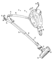
- reference numeral 11 denotes a so-called canister-type vacuum cleaner.
- the vacuum cleaner 11 includes a vacuum cleaner body 12 and a separate pipe from the vacuum cleaner body 12 detachably connected to the vacuum cleaner body 12. And a wind path forming body 13 as a part.
- the vacuum cleaner main body 12 includes a hollow main body case 15 that can swivel and run on the surface to be cleaned, and a main body dust collection chamber and an electric blower chamber (not shown) are partitioned in the front and rear in the main body case 15. Has been. Furthermore, an electric blower 18 is accommodated in the electric blower chamber, and the suction side of the electric blower 18 communicates with the main body dust collection chamber. Further, a dust collecting section such as a filter, a dust collecting bag, or a dust collecting device (dust collecting cup) is disposed in the main body dust collecting chamber.
- a main body suction port 19 is formed in the front portion of the main body case 15 so as to communicate with the main body dust collection chamber and to which the proximal end side of the air passage forming body 13 is connected. Further, a display unit 20 such as a liquid crystal panel as a notification unit is disposed on the upper part of the main body case 15.
- the direction along the traveling direction of the vacuum cleaner 11 is defined as the front-rear direction
- the left-right direction (both directions) intersecting (orthogonal) the front-rear direction is described as the width direction.
- the air passage forming body 13 includes a long hose body 21, an extension pipe 22 that is detachably connected to the hose body 21, and a suction portion that is detachably connected to the extension pipe 22.
- the floor brush 23 which is a mouth is provided, and an air passage W communicating with the suction side of the electric blower 18 is formed inside.
- the air path forming body 13 can be used with the floor brush 23 removed, for example, or the floor brush 23 and the extension pipe 22 can be removed.
- the hose body 21 includes a long cylindrical hose body 25, a connecting pipe portion 26 formed in communication with the base end side (downstream end side) which is one end side of the hose body 25,
- a hand operating part 27 for gripping operation of the air passage forming body 13 is formed integrally with the front end side (upstream end side) which is the end side.
- the hose body 25 is formed in a cylindrical bellows shape using a flexible synthetic resin or the like, and a wiring (not shown) that electrically connects the hand operating section 27 side and the cleaner body 12 side is provided inside and the air passage. It is attached to the outside of W in a spiral shape.
- the connecting pipe portion 26 is a portion that is inserted and connected to the main body suction port 19 and is formed in a cylindrical shape by a synthetic resin harder than the hose main body 25 or the like.
- a terminal (not shown) that is electrically connected to the wiring disposed in the hose body 25 is disposed in the connecting pipe part 26, and these terminals insert the connecting pipe part 26 into the main body suction port 19. By connecting, it is electrically connected to the cleaner body 12 side.
- the hand operating portion 27 is formed in a substantially cylindrical shape with a synthetic resin harder than the hose body 25, and a gripping portion 37 gripped by the user protrudes from the upstream end side to the downstream end side. Is formed.
- a plurality of setting buttons 38 serving as setting means for setting the operation of the electric blower 18 and the like are disposed on the grip portion 37.
- the floor brush 23 can constitute a part (upstream end) of the air passage W, and a connection pipe 41 whose one end side is connected to the distal end side (upstream end side) of the extension pipe 22 and this connection
- a horizontally long case body 42 connected to the other end side of the tube 41 so as to be rotatable in the vertical direction or the circumferential direction, and the case body 42 is rotatably provided to be grounded to the surface to be cleaned and driven to rotate.
- a traveling wheel (not shown) that enables the floor brush 23 to move (run) on the surface to be cleaned.
- a suction port that communicates with the other end side of the connecting pipe 41 is formed in the lower portion of the case body 42 facing the floor surface.
- a rotary brush as a rotary cleaning body is rotatably arranged at the suction port, and a rotary motor or the like as a cleaning body driving means for rotating the rotary brush is arranged in the case body 42. May be.
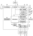
- the vacuum cleaner 11 includes a control means 45 such as a microcomputer that receives power from a commercial AC power source e that is a power source unit shown in FIG.
- a control means 45 such as a microcomputer that receives power from a commercial AC power source e that is a power source unit shown in FIG.
- a battery such as a secondary battery built in the main body case 15 of the cleaner main body 12 can be used.
- the control unit 45 is an operation determination unit 51 that is an operation determination unit electrically connected to the setting button 38, and an electric power that is a power control unit that is electrically connected to the operation determination unit 51 and controls the operation of the electric blower 18.
- the control unit 52, the processing unit 54 that is a processing unit electrically connected to the optical sensor 53 that is a dust amount detection unit that detects the amount of dust passing through the air passage W by driving the electric blower 18, and the processing unit 54 The operation time as an operation time integration means for detecting the operation time of the dust amount integration unit 55 as an electrically connected dust amount integration means and the operation time of the electric blower 18 (the time during which the electric blower 18 is continuously driven from the start of driving) Accumulation unit 56, movement amount (movement distance) of floor brush 23 on the surface to be cleaned and movement amount / time accumulation unit 57 as a movement amount / time integration means for integrating the time, suction time for actually sucking dust Suction time integration unit 58 that integrates, cleaning ability And cleaning efficiency calculating unit 59,
- the control means 45 may include a cleaning body drive means control section for controlling the driving of the rotary motor and the like when the rotary motor and the like are disposed on the floor brush 23, for example. Further, each part constituting the control means 45 may be integrated or separated, and can be arranged at an arbitrary position, for example, inside the main body case 15 of the cleaner body 12.
- the operation determination unit 51 sets the operation mode of the electric blower 18 for the power control unit 52 according to the operation of the setting button 38 by determining the operation of the setting button 38 by the user.
- the power control unit 52 can control the electric blower 18, for example, the phase angle via a control element (not shown) according to the operation mode set by the operation determination unit 51.
- the optical sensor 53 is, for example, a light emitting unit 61 as a light emitting unit that emits infrared light, and a light receiving unit that receives the infrared light emitted by the light emitting unit 61.
- the light receiving unit 62 is provided at a position facing each other, and a signal corresponding to the amount of dust passing through the air passage W is generated by the amount of infrared light received by the light receiving unit 62 from the light emitting unit 61. Can be output.
- the light emitting unit 61 includes a light emitting element 61a such as an LED that outputs light such as infrared light, and one and other light emitting sides as a light emitting side light guide member that guides light emitted from the light emitting element 61a into the air path W. And lenses 61b and 61c.
- the light emitting element 61a is disposed, for example, at the upper part of the main body suction port 19 of the main body case 15 of the vacuum cleaner main body 12, and is configured to output infrared light downward.
- one light-emitting side lens 61b is disposed on the inner surface of the main body suction port 19 below the light-emitting element 61a on the infrared light output side.
- the other light-emitting side lens 61c is disposed at a position facing the lower side of the light-emitting element 61a (light-emitting side lens 61b) in a state where the connecting pipe portion 26 of the air passage forming body 13 is connected to the main body suction port 19. .
- the other light-emitting side lens 61c is fitted in a light-emitting side hole 61d formed in the connecting pipe portion 26 along the radial direction so as to air-tightly close the light-emitting side hole 61d.
- One end side faces the light emitting element 61a side (light emitting side lens 61b side), and the other end side faces the inside of the air passage W. That is, the air in the air passage W does not flow out of the air passage W from the light emitting side hole 61d.
- the light receiving unit 62 includes a light receiving element 62a such as a phototransistor that detects infrared light output from the light emitting unit 61, and a light receiving side light guide member that guides the light output from the light emitting unit 61 to the light receiving element 62a. And the other light-receiving side lenses 62b and 62c.
- the light receiving element 62a is disposed, for example, at the lower part of the main body suction port 19 of the main body case 15 of the vacuum cleaner body 12 and facing upward, that is, toward the light emitting element 61a, and receives infrared light output from the light emitting element 61a And, it is configured to output a signal corresponding to the amount of received light.
- one light receiving side lens 62b is disposed on the inner surface of the main body suction port 19 above the infrared light input side with respect to the light receiving element 62a.
- the other light receiving side lens 62c is disposed at a position facing the light receiving element 62a (light receiving side lens 62b) with the connecting pipe portion 26 of the air passage forming body 13 connected to the main body suction port 19. .
- the other light receiving side lens 62c is fitted in a light receiving side hole 62d formed in the connecting pipe portion 26 along the radial direction so as to airtightly close the light receiving side hole 62d.
- One end side faces the light receiving element 62a side (light receiving side lens 62b side), and the other end side faces the inside of the air passage W. That is, the air in the air passage W does not flow out of the air passage W from the light receiving side hole 62d.
- the optical sensor 53 increases (decreases) dust that blocks light emission from the light emitting element 61a of the light emitting unit 61. Since the amount of light received by the light receiving element 62a relatively decreases (increases), the amount of dust passing through the air passage W can be detected by increasing or decreasing the amount of received light.
- the processing unit 54 includes a light emission control unit 64 that controls the light emission amount of the light emitting element 61a of the light emitting unit 61, and a light reception processing unit 65 that processes a signal from the light receiving unit 62, and integrates the dust amount.
- the unit 55 is electrically connected.
- the light receiving processing unit 65 is configured to amplify a signal from the light receiving element 62a of the light receiving unit 62 output corresponding to the amount of received light and output the amplified signal to the cleaning efficiency calculating unit 59.
- the dust amount integrating unit 55 calculates the integrated amount of dust while the electric blower 18 is driven by integrating the signals processed by the light receiving processing unit 65 of the processing unit 54.
- the operation time integrating unit 56 has a function such as a timer, for example, and is reset when the electric blower 18 starts to be driven, and the time during which the electric blower 18 is driven or the time until the electric blower 18 is stopped. It is calculated by integrating.
- the movement amount / time integration unit 57 is electrically connected to the ground detection unit 67 and the movement amount detection unit 68 arranged on the floor brush 23.
- the grounding detection unit 67 is a switch or the like protruding from the bottom of the case body 42 of the floor brush 23, and can detect the grounding to the surface to be cleaned by being turned on or off by contacting the surface to be cleaned.
- the movement amount detection unit 68 is, for example, a sensor that can detect the movement speed and distance of the floor brush 23 by detecting the rotation speed or the rotation speed of the traveling wheels of the case body 42.
- the moving amount / time integrating unit 57 integrates the moving speed and distance of the floor brush 23 detected by the moving amount detecting unit 68 in a state where the ground detecting unit 67 detects the grounding of the floor brush 23, Calculate the amount of movement of the floor brush 23 on the surface to be cleaned and calculate the amount of time the floor brush 23 has moved on the surface to be cleaned by integrating the time when the grounding detector 67 detects the ground contact of the floor brush 23. To do.
- the suction time integration unit 58 has a function such as a timer, for example, and is reset when the electric blower 18 starts to be driven.
- the amount of dust detected by the optical sensor 53 is equal to or more than a predetermined amount set in advance. By accumulating, the actual (substantial) dust suction time is calculated.
- the cleaning efficiency calculation unit 59 has a function of detecting the attachment / detachment of the floor brush 23 with respect to the air passage W (FIG. 3), and the integrated amount of dust, the amount of movement / time integration calculated by the dust amount integration unit 55 The amount and time of movement of the floor brush 23 on the surface to be cleaned calculated by the unit 57, the operation time of the electric blower 18 calculated by the operation time integrating unit 56, and the suction time calculated by the suction time integrating unit 58 Based on the above, the cleaning efficiency is calculated.
- the cleaning efficiency calculation unit 59 is electrically connected to a data storage unit 69 such as a non-volatile memory, for example, and the cleaning efficiency at the time of several previous cleanings stored in the data storage unit 69, or A current work efficiency index is calculated based on an average value such as the cleaning efficiency at the time of cleaning in the past certain period.
- the function of detecting the attachment / detachment of the floor brush 23 may be provided with a dedicated detection unit in the control means 45, or may be provided in any other part of the control means 45.
- the display control unit 60 controls the display means 20 so as to display the cleaning efficiency and the work efficiency index calculated by the cleaning efficiency calculation unit 59.
- the commercial AC power source e is supplied to the control means 45. Power (voltage) is supplied (applied) from
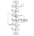
- control means 45 waits for an operation input of the setting button 38. That is, the control means 45 determines whether or not the setting button 38 for starting the electric vacuum cleaner 11, in other words, for starting the electric blower 18, has been operated (by the operation determination unit 51) (step 1).
- step 1 when the control means 45 determines that the vacuum cleaner 11 is not started (the setting button 38 is not operated), step 1 is repeated to start the vacuum cleaner 11 (the setting button 38 is If it is determined that the operation has been performed), the control means 45 activates the vacuum cleaner 11 (electric fan 18) in the set operation mode (by the power control unit 52) (step 2), and the air path W ( It is determined (by the cleaning efficiency calculation unit 59) whether or not the floor brush 23 is connected to the tip (upstream end) of the extension pipe 22 (step 3).
- step 3 when the control means 45 determines that the floor brush 23 is connected, the first control shown in FIG. 5 is performed (step 4), and if the floor brush 23 is not connected, the control means 45. Is determined, the second control shown in FIG. 6 is performed (step 5).
- the dust sucked into the air passage W together with the air by driving the electric blower 18 passes through the air passage forming body 13 and the main body suction port 19 and flows into the dust collecting portion, and is collected by the dust collecting portion. .
- the air in which the dust is collected is sucked into the electric blower 18 and is exhausted from the electric blower 18 while cooling the electric blower 18 and is discharged to the outside of the main body case 15 of the cleaner body 12.
- step 4 and step 5 the control means 45 determines whether or not the setting button 38 for stopping the electric vacuum cleaner 11 (electric blower 18), in other words, the electric blower 18 is operated (operation determination). Determination by the unit 51 (step 6). If the control means 45 determines in step 6 that the vacuum cleaner 11 is not stopped (the setting button 38 is not operated), the process returns to step 3 to stop the vacuum cleaner 11 (setting button). If it is determined that the control unit 45 has been operated), the control unit 45 stops the electric blower 18 (by the power control unit 52) (step 7) and ends the cleaning.
- this determination can be interrupted at any timing during the first control and the second control. The first control and the second control can be switched according to the connection or removal of the floor brush 23 determined at that time.
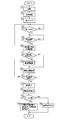
- the control means 45 clears the display on the display means 20 (by the display control unit 60) (step 11), and then the vacuum cleaner 11 is sucking air properly, in other words, the electric blower 18 functions. It is determined whether or not (step 12).
- the electric blower 18 is not functioning, for example, when air is not sucked in due to clogging of the dust collecting part, or when the air passage W is blocked by foreign matter or the like, and the control means 45. If it is determined, the process returns to step 12, and if it is determined that the electric blower 18 is functioning, the control means 45 determines whether or not the floor brush 23 is grounded on the surface to be cleaned (ground detection unit). 67) (Step 13).
- step 13 when the control means 45 determines that the floor brush 23 is not grounded on the surface to be cleaned, the process returns to step 13 (or step 12), and the floor brush 23 is grounded on the surface to be cleaned. If it is determined, the control means 45 determines (by the movement amount detection unit 68) whether or not the floor brush 23 is moving at a speed equal to or higher than a preset predetermined speed (step 14).
- Step 14 when the control means 45 determines that the floor brush 23 is not moving at a speed equal to or higher than a predetermined speed, the process returns to Step 13 (or Step 12), and the floor brush 23 is When determining that the vehicle is moving at a speed equal to or higher than a predetermined speed set in advance, the control means 45 calculates the movement amount and movement time of the floor brush 23 on the surface to be cleaned (the movement amount / time integration unit 57). (According to step 15).
- control means 45 determines whether or not the amount of dust detected by the optical sensor 53 is greater than or equal to a predetermined amount set in advance (step 16). If it is determined in step 16 that the amount of dust detected by the optical sensor 53 is greater than or equal to a predetermined amount set in advance, the control means 45 integrates the dust amount (by the dust amount integration unit 55) (step 17) Go to step 18. If the control means 45 determines in step 16 that the amount of dust detected by the optical sensor 53 is not equal to or greater than a predetermined amount, the process proceeds to step 18 as it is.
- the control means 45 integrates the operation time of the electric blower 18 (by the operation time integration unit 56) (step 18), and the movement amount and movement time of the floor brush 23 on the surface to be cleaned accumulated in step 15
- control means 45 integrates the actual dust suction time (by the suction time integration section 58) (step 33).
- control means 45 determines whether (via the processing unit 54) the amount of dust detected by the optical sensor 53 is equal to or greater than a predetermined amount (step 34). If it is determined in step 34 that the amount of dust detected by the optical sensor 53 is greater than or equal to a predetermined amount set in advance, the control means 45 integrates the dust amount (by the dust amount integration unit 55) (step 35), go to step 36. If the control means 45 determines in step 34 that the amount of dust detected by the optical sensor 53 is not greater than a predetermined amount set in advance, the process proceeds to step 36 as it is.
- the control means 45 integrates the operation time of the electric blower 18 (by the operation time integration unit 56) (step 36), the suction time accumulated in step 33, the accumulated amount of dust accumulated in step 35, and Based on the operation time accumulated in step 36, the cleaning efficiency calculation unit 59 calculates the cleaning efficiency (step 37).
- the control means 45 performs the control of Steps 38 to 40 similar to Steps 20 to 22, and then proceeds to Step 6.
- the cleaning efficiency calculation unit 59 calculates the cleaning efficiency by dividing the accumulated amount of dust by the product of the moving amount and the moving time of the floor brush 23.
- the calculated cleaning efficiency increases as the movement amount or the movement time of the floor brush 23 decreases with respect to the integrated amount of dust.
- the calculated cleaning efficiency can be used as an indicator of whether or not the cleaning area has been efficiently cleaned.
- the cleaning efficiency calculation unit 59 calculates the cleaning efficiency by dividing the accumulated amount of dust by the product of the operation time of the electric blower 18 and the actual suction time. Therefore, the smaller the operation time of the electric blower 18 or the actual suction time is, the larger the calculated cleaning efficiency is. Therefore, even when the floor brush 23 is removed and cleaned, the above-described calculated cleaning efficiency is efficiently used in the cleaning area. It can be used as an indicator of whether or not the cleaning has been completed.
- the electric vacuum cleaner 11 includes detection means 71 (FIG. 8) capable of detecting the type of the cleaning area (cleaning area).
- This detecting means 71 is a sensor that detects the type of the cleaning area by reading a detected member (not shown), for example, a barcode or an IC tag, which is arranged at a specific position for each cleaning area such as a room, for example. Etc. are used.
- the detection means 71 is electrically connected to a cleaning area determination section 72 as a determination section of the control means 45.
- the cleaning area determination unit 72 is electrically connected to the cleaning efficiency calculation unit 59, can determine the type of the cleaning area detected by the detection means 71, and can output the determination result to the cleaning efficiency calculation unit 59. It is.
- the control means 45 detects the type of the cleaning area by the detection means 71 and determines the type (by the cleaning area determination unit 72). Determine (step 45).
- a cleaning efficiency or a work efficiency index is displayed for each type of cleaning area. For example, in FIG. 10, the cleaning efficiency and work efficiency index of each cleaning area are displayed side by side.
- the cleaning efficiency or work efficiency index is calculated by the cleaning efficiency calculation unit 59 for each type of cleaning area detected by the detection means 71, and the calculated cleaning efficiency or work efficiency is calculated.
- the efficiency index is displayed on the display means 20, data for each cleaning area can be accumulated, and the cleaning achievement can be more reliably evaluated and notified.
- the detection means 71 automatically detects the type of the cleaning area only by the user cleaning, no input work or the like is required, and usability is further improved.
- the detection means 71 may detect, for example, the type of the surface to be cleaned, for example, whether the surface to be cleaned is a flooring, a carpet, or a tatami mat. Each of the type of surface and the cleaning area may be detected. Then, the display unit 20 displays the cleaning efficiency or the work efficiency index in correspondence with at least one of the detected type of the surface to be cleaned and the type of the cleaning area, whereby the second embodiment described above. The same operational effects can be achieved.
- the electric vacuum cleaner 11 includes setting means 75 (FIG. 11) that allows the user to manually select the type of the cleaning area (cleaning area). .
- the setting means 75 is disposed, for example, on the hand operation section 27 or the upper part of the main body case 15 of the cleaner body 12, and is electrically connected to the operation determination section 51 of the control means 45.
- the operation determination unit 51 determines the setting operation of the setting button 38 and the setting unit 75, outputs the result of the setting operation of the setting button 38 to the power control unit 52, and the result of the setting operation of the setting unit 75 is Output to the cleaning area determination unit 72.
- the cleaning area determination unit 72 can determine the type of the cleaning area detected by the setting means 75 and output the determination result to the cleaning efficiency calculation unit 59.
- the setting means 75 uses an operation key or the like for determining a name that can be specified by the user for each cleaning area by using a number or the like and inputting it.
- control means 45 determines the type of the surface to be cleaned input by the user via the setting means 75 (the operation determination unit 51). And by the cleaning area determination unit 72) (step 47).
- the cleaning efficiency or the work efficiency index is displayed for each type of the cleaning area, as in the second embodiment.
- the cleaning efficiency or work efficiency index is calculated by the cleaning efficiency calculation unit 59 for each type of cleaning area input by the setting means 75, and the calculated cleaning efficiency or By displaying the work efficiency index on the display means 20, it is possible to accumulate data for each cleaning area, and to more reliably evaluate and notify the cleaning achievement level.
- the setting means 75 can more reliably determine the cleaning area.
- the setting means 75 may be capable of inputting, for example, the type of the surface to be cleaned, for example, whether the surface to be cleaned is a flooring, a carpet, or a tatami mat. Each of the surface type and the cleaning area may be input. Then, the cleaning efficiency or the work efficiency index is displayed by the display means 20 corresponding to at least one of the set type of the surface to be cleaned and the type of the cleaning area, whereby the third embodiment described above. The same operational effects can be achieved.
- step 16 and step 17 may be performed before the processing of step 13 to step 15 described above. In other words, the order of the processing of step 13 to step 15 and the processing of step 16 and step 17 does not matter.
- the cleaning efficiency calculation unit 59 is in a state where the floor brush 23 is removed from the air passage W, and the operation time of the electric blower 18 is equal to or more than a predetermined amount set in advance. Even if the floor brush 23 is removed and cleaned, the cleaning efficiency is calculated on the basis of the actual suction time when the dust is sucked into the air passage W and the accumulated amount of dust detected by the optical sensor 53. As in the case of cleaning using the brush 23, it is possible to effectively notify the user of the degree of cleaning achievement.
- the cleaning efficiency and work efficiency index can express the user's level of cleaning achievement and give a sense of accomplishment. Not only can the complexity of the cleaning work be eliminated, but also the cleaning efficiency can be improved. Can contribute to energy saving.
- the vacuum cleaner 11 of the fourth embodiment is a so-called robot provided with a vacuum cleaner main body 77 as a suction portion instead of the vacuum cleaner main body 12 and the air passage forming body 13 (floor brush 23) of the above embodiments.
- This is a vacuum cleaner of the type (autonomous movement (autonomous traveling) type).
- the cleaner main body 77 includes, for example, a hollow main body case 81, an electric blower 18 accommodated in the main body case 81, and a suction side of the electric blower 18.
- the dust collecting part 82 provided in the main body case 81 in communication with the cleaner body 77 autonomously travels, that is, for example, driving wheels 83 as a plurality of driving parts for autonomous traveling, and driving for driving these driving wheels 83
- a motor 84 as means, a swivel wheel 85 attached to the lower portion of the main body case 81 so as to be turnable, a plurality of sensors 86 as detection means attached to the main body case 81, a control means 45, and a power supply unit
- a secondary battery 87 which is a battery to be operated.
- the vacuum cleaner main body 77 may further include a side brush or the like as a swivel cleaning unit below the main body case 81. Moreover, the cleaner main body 77 makes the up-down direction of FIG. 14 and FIG. 15 the front-back direction, for example.
- the main body case 81 is formed in a flat columnar shape (disk shape), for example, with synthetic resin or the like, and is formed in a longitudinal direction in the width direction, i.e., a horizontally elongated collection, near the rear portion of the circular lower surface 81a.
- a suction port 91 as a dust port is formed as an opening.
- the display means 20 the operation unit 92, and the like are arranged in the upper part of the main body case 81.
- the operation unit 92 is for a user to perform an external input operation, and is configured by, for example, a touch panel.
- the suction port 91 communicates with the dust collecting part 82. Further, a shaft-like rotary brush 93 as a rotary cleaning body is rotatably supported by the suction port 91.
- the rotary brush 93 serves as a cleaning body driving means attached in the main body case 81.
- the rotary motor 94 is driven to rotate.
- the rotating brush 93 is configured, for example, by attaching a plurality of cleaning body portions protruding in a wall shape spirally in the radial direction on the outer peripheral surface of a long shaft portion.
- the rotating brush 93 has a lower side protruding from the suction port 91 to the lower side 81a of the lower surface 81a of the main body case 81, and a cleaning body positioned on the lower side with the vacuum cleaner 11 placed on the surface to be cleaned. It is comprised so that the front-end
- the dust collecting unit 82 collects dust sucked from the suction port 91 by driving the electric blower 18, and is configured to filter and collect dust using a dust bag such as a paper pack or a filter, or by centrifugation. Any configuration can be used, such as a configuration in which dust is separated and collected by inertial separation such as (cyclonic separation) or rectilinear separation. Further, the dust collecting part 82 is located at the rear part of the main body case 81 above the suction port 91 and is detachable from the main body case 81. Further, an optical sensor 53 is disposed at a position between the dust collection part 82 and the suction port 91.
- Each drive wheel 83 protrudes downward from the lower surface 81a of the main body case 81 at least on the lower side, and can rotate by contacting the surface to be cleaned with the vacuum cleaner 11 placed on the surface to be cleaned. Yes. Further, these drive wheels 83 are positioned on both sides of a substantially central portion in the front-rear direction of the main body case 81, for example, in front of the suction port 91, and are configured to rotate along the front-rear direction.
- Each motor 84 is disposed, for example, corresponding to each drive wheel 83, and can drive each drive wheel 83 independently. These motors 84 may be directly connected to each drive wheel 83, or may be connected to each drive wheel 83 via transmission means (not shown) such as a gear or a belt.
- the turning wheel 85 is a driven wheel that is located at a substantially central part in the width direction of the main body case 81 and at the front part, and can turn along the surface to be cleaned.
- the sensor 86 is, for example, a distance measuring sensor such as an ultrasonic sensor or an infrared sensor, or a contact sensor that becomes a bumper by directly contacting an obstacle, and the front part of the cleaner body 77 (main body case 81). , Arranged on the side or lower part, etc., whether there is an obstacle (wall) in front of the vacuum cleaner main body 77 (main body case 81), an obstacle on the side (wall), or an obstacle (step) on the lower side, In addition, the distance between them and the vacuum cleaner main body 77 (main body case 81) can be detected.
- the control means 45 is electrically connected to the electric blower 18, the rotary motor 94, each motor 84, and the sensor 86, and based on the detection result by the sensor 86, the electric blower 18, the rotary motor 94, and each motor.
- the drive such as 84 can be controlled.
- a plurality of cleaning modes of the electric vacuum cleaner 11 are set in the control means 45, and these cleaning modes can be selected by an external input of the operation unit 92 by the user.
- these cleaning modes for example, a normal cleaning mode which is a main cleaning mode in which the entire cleaning area is autonomously moved (autonomous traveling) and cleaned, and the entire cleaning area is cleaned a plurality of times, for example, twice, while autonomously moving (autonomous traveling).
- a careful cleaning mode that is an intensive cleaning mode, a partial cleaning mode that spot-cleans only a predetermined portion of the cleaning area, and the like are stored in advance.
- the movement (running) patterns of the electric vacuum cleaner 11 (the vacuum cleaner main body 77) cross each other (perpendicular), for example, at each time of cleaning (during the first cleaning and the second cleaning). It is possible to change the direction of the cleaning, etc., so that the cleaning can be performed more effectively.
- the control means 45 includes the power control unit 52, the processing unit 54, the dust amount integrating unit 55, the operation time integrating unit 56, the movement amount / time integrating unit 57, the suction time integrating unit 58, the cleaning efficiency calculating unit 59, the display
- an operation determination unit 96 electrically connected to the operation unit 92, a rotary motor control unit 97 as a cleaning body drive means control unit that controls the operation of the rotary motor 94, Travel control unit 98 that is a movement control unit that controls the movement (travel) of the vacuum cleaner 11 (the vacuum cleaner body 77) by controlling the operation of each motor 84, and travel that is electrically connected to the sensor 86
- a processing unit 99 is provided.
- Each part constituting the control means 45 may be integral or separate, and can be arranged at an arbitrary position, for example, inside the main body case 15 of the cleaner body 12.
- the operation determination unit 96 sets the cleaning mode for the power control unit 52, the rotary motor control unit 97, and the travel control unit 98 by determining the operation of the operation unit 92.
- the rotation motor control unit 97 can control the phase angle of the rotation motor 94, for example, via a control element (not shown) according to the cleaning mode set by the operation determination unit 96.
- the movement amount / time integration unit 57 is electrically connected to, for example, a rotary motor control unit 97, and the rotary motor 94 (drive wheel) driven by the rotary motor control unit 97 while being grounded to the surface to be cleaned.
- 83) is a sensor serving as a rotational speed detecting means capable of detecting the moving speed and distance of the vacuum cleaner 11 (the vacuum cleaner body 77) by detecting the rotational speed or the rotational speed of 83). Then, the moving amount / time integrating unit 57 adds up the detected moving speed and distance of the electric vacuum cleaner 11 (the vacuum cleaner main body 77) to thereby increase the amount of movement on the surface to be cleaned of the electric vacuum cleaner 11 (the vacuum cleaner main body 77).
- each driving wheel 83 is grounded with respect to the surface to be cleaned is detected, for example, by detecting the load current value of the rotary motor 94, or the grounding detecting portion is attached to the lower surface 81a of the main body case 81, etc. It can be provided separately and detected.
- the cleaning efficiency calculating unit 59 is provided on the surface to be cleaned of the vacuum cleaner 11 (vacuum cleaner body 77) calculated by the accumulated amount of dust calculated by the dust amount integrating unit 55 and the moving / time integrating unit 57.
- the cleaning efficiency is calculated on the basis of the movement amount and movement time of the motor, the operation time of the electric blower 18 calculated by the operation time integration unit 56, the suction time calculated by the suction time integration unit 58, and the like.
- the secondary battery 87 supplies power to the control means 45, the electric blower 18, the rotary motor 94, each motor 84, the sensor 86, and the like.
- the secondary battery 87 is disposed, for example, at a position behind the turning wheel 85.
- the secondary battery 87 is electrically connected to the charging terminals 101 and 101 located on the lower surface 81a of the main body case 81 on both sides of the swivel wheel 85, and is installed at a predetermined position in the room (room), for example. Charging is possible by connecting charging terminals 101 and 101 to a predetermined charging stand (not shown).
- the control means 45 starts the electric blower 18 (by the power control unit 52) in the set cleaning mode (step 51), and processes information (such as the distance to the obstacle) detected by the sensor 86 (by the travel processing unit 99).
- the driving wheels 83 and 83 are driven by driving the motors 84 and 84 (by the travel control unit 98), and the vacuum cleaner 11 (the vacuum cleaner body 77) moves autonomously in accordance with the set cleaning mode. (Autonomous running) (step 52).
- control means 45 clears the display of the display means 20 (by the display control unit 60) (step 53), whether the vacuum cleaner 11 is sucking air properly, in other words, the electric blower 18 functions. It is determined whether or not (step 54).
- step 54 when the electric blower 18 is not functioning, for example, when air is not sucked in due to clogging of the dust collecting part 82, or when the suction port 91 is blocked by foreign matter or the like, the control means If 45 is determined, the process returns to step 54, and if it is determined that the electric blower 18 is functioning, the control means 45 determines whether the electric vacuum cleaner 11 (the vacuum cleaner body 77) is set at a predetermined speed. It is determined whether or not the vehicle is moving at the above speed (by the movement amount detection unit 68) (step 55). The dust sucked from the suction port 91 together with the air by driving the electric blower 18 is collected in the dust collecting portion 82. The air in which the dust is collected is sucked into the electric blower 18 and is exhausted from the electric blower 18 while cooling the electric blower 18 and is discharged to the outside of the main body case 81 of the cleaner main body 77.
- step 55 if the control means 45 determines that the electric vacuum cleaner 11 (the vacuum cleaner body 77) is not moving at a speed equal to or higher than a predetermined speed set in advance, the process proceeds to step 55 (or step 54). Returning, if it is determined that the vacuum cleaner 11 (the vacuum cleaner body 77) is moving at a predetermined speed or higher, the control means 45 The movement amount and the movement time on the surface to be cleaned are integrated (by the movement amount / time integration unit 57) (step 56).
- the control means 45 determines whether or not the amount of dust detected by the optical sensor 53 is greater than or equal to a predetermined amount set in advance (step 57). If it is determined in step 57 that the amount of dust detected by the optical sensor 53 is greater than or equal to a predetermined amount set in advance, the control means 45 integrates the dust amount (by the dust amount integrating unit 55) (step 57). 58) The operation time of the electric blower 18 is accumulated (by the operation time accumulation unit 56) (step 59). If the control means 45 determines in step 57 that the amount of dust detected by the optical sensor 53 is not equal to or greater than a predetermined amount set in advance, the process proceeds to step 59 as it is.
- the control means 45 determines whether or not to continue operating the vacuum cleaner 11 (electric blower 18) (step 60), and returns to step 54 when determining to operate. If it is determined in step 60 that the operation is to be terminated, the electric blower 18 is stopped and the electric vacuum cleaner 11 (the vacuum cleaner main body 77) is moved to the charging stand, and the charging terminals 101 and 101 are connected to the charging stand. Cleaning is terminated in the connected state (step 61). Next, the control means 45 is based on the movement amount and movement time on the surface to be cleaned of the electric vacuum cleaner 11 (vacuum cleaner body 77) accumulated in step 56, and the accumulated amount of dust accumulated in step 58. The cleaning efficiency is calculated by the cleaning efficiency calculation unit 59 (step 62).
- the method for calculating the cleaning efficiency in step 62 is the same as that in step 19 described above, and is therefore omitted. Thereafter, the control means 45 determines whether or not the average value is stored in the data storage unit 69 (step 63). If it is determined in step 63 that the average value is stored in the data storage unit 69, the control unit 45 calculates the work efficiency index by the cleaning efficiency calculation unit 59, and displays the display unit 20 (display control unit). By controlling (by 60), the work efficiency index is displayed together with the cleaning efficiency (step 64). The calculation method of the work efficiency index in step 64 is the same as that in step 21 described above, and is therefore omitted. On the other hand, if it is determined in step 63 that the average value is not stored in the data storage unit 69, the control unit 45 displays only the cleaning efficiency by controlling the display unit 20 (by the display control unit 60). (Step 65).
- the cleaning efficiency calculation unit 59 calculates the cleaning efficiency by dividing the accumulated amount of dust by the product of the movement amount and the movement time of the cleaner body 77.
- the calculated cleaning efficiency increases as the moving amount or moving time of the cleaner main body 77 decreases with respect to the integrated amount of dust.
- the calculated cleaning efficiency can be used as an indicator of whether or not the cleaning area has been efficiently cleaned.
- the cleaning achievement level can be expressed by the cleaning efficiency and the work efficiency index, the user can be urged to improve the cleaning efficiency by changing the setting of the cleaning mode, etc., contributing to energy saving. it can. That is, for example, when the cleaning efficiency in the careful cleaning mode is relatively low, or when the cleaning efficiency in the normal cleaning mode is relatively low, it can be determined that the autonomous movement distance of the cleaner body 77 is wasteful. Therefore, the cleaning efficiency can be increased by changing the setting of the cleaning mode, for example, the normal cleaning mode or the partial cleaning mode is set, and an appropriate cleaning mode can be selected.
- the cleaning mode is not only selected from those stored in advance, but may be arbitrarily set by the user, for example. Further, the setting of the cleaning mode may include not only the setting of the movement (running) pattern of the cleaner body 77 but also the setting of the input (operation mode) of the electric blower 18.
- the type of the cleaning area (cleaning area) is automatically detected or manually input by the user.
- the cleaning efficiency or work efficiency index may be calculated by the cleaning efficiency calculation unit 59, and the calculated cleaning efficiency or work efficiency index may be displayed on the display means 20. Also in this case, the same effects as those of the second and third embodiments can be obtained.
- the configuration in which the vacuum cleaner 11 (the vacuum cleaner main body 77) autonomously moves (autonomous traveling) is not only the configuration in which the sensor 86 moves (runs) while detecting an obstacle or the like, but also, for example, a preset movement A configuration that automatically moves (runs) along a (running) pattern (a configuration that self-runs) is also included.
- the vacuum cleaner 11 (the vacuum cleaner body 77) that moves autonomously (autonomous traveling) may be manually operated using a remote controller or the like.
- the cleaning efficiency calculation unit 59 calculates the cleaning efficiency, and the calculated cleaning efficiency is displayed on the display means 20, so that the cleaning efficiency is displayed to the user. Achievement can be notified effectively.
- the cleaning efficiency calculating unit 59 may calculate the average value when there is an average value such as the cleaning efficiency during the previous several times of cleaning stored in the data storage unit 69 or the cleaning efficiency during the cleaning for a certain period in the past.
- the work efficiency index is calculated by dividing the cleaning efficiency in step (b), and the calculated work efficiency index is displayed on the display means 20 to indicate to the user whether the cleaning efficiency has improved as compared with the past cleaning. It can be recognized, and the user can be notified of the cleaning achievement level more effectively.
- the display means 20 displays the cleaning efficiency and the work efficiency index in real time during cleaning, but is displayed when cleaning ends, that is, when the electric blower 18 (electric vacuum cleaner 11) is stopped. You may comprise.
- the notification means can be notification means for audibly informing, for example, by voice, or a combination thereof.
- control means 45 may automatically control the input of the electric blower 18 or the motor of the floor brush 23 in accordance with the amount of dust detected by the optical sensor 53.
- the vacuum cleaner 11 is not limited to a canister type or a robot type, and can be used in correspondence with an upright type or a handy type in which a floor brush 23 is connected to the lower part of the vacuum cleaner body 12. .
Priority Applications (5)
| Application Number | Priority Date | Filing Date | Title |
|---|---|---|---|
| RU2013143794/12A RU2552763C2 (ru) | 2011-03-28 | 2012-03-28 | Электропылесос |
| KR1020137025205A KR101471322B1 (ko) | 2011-03-28 | 2012-03-28 | 전기 청소기 |
| CN201280014645.XA CN103476314B (zh) | 2011-03-28 | 2012-03-28 | 电动吸尘器 |
| JP2012531170A JP5321869B2 (ja) | 2011-03-28 | 2012-03-28 | 電気掃除機 |
| EP12763029.1A EP2692271B1 (en) | 2011-03-28 | 2012-03-28 | Electric vacuum cleaner |
Applications Claiming Priority (2)
| Application Number | Priority Date | Filing Date | Title |
|---|---|---|---|
| JP2011070745 | 2011-03-28 | ||
| JP2011-070745 | 2011-03-28 |
Publications (1)
| Publication Number | Publication Date |
|---|---|
| WO2012133571A1 true WO2012133571A1 (ja) | 2012-10-04 |
Family
ID=46931278
Family Applications (1)
| Application Number | Title | Priority Date | Filing Date |
|---|---|---|---|
| PCT/JP2012/058215 WO2012133571A1 (ja) | 2011-03-28 | 2012-03-28 | 電気掃除機 |
Country Status (6)
| Country | Link |
|---|---|
| EP (1) | EP2692271B1 (ko) |
| JP (1) | JP5321869B2 (ko) |
| KR (1) | KR101471322B1 (ko) |
| CN (1) | CN103476314B (ko) |
| RU (1) | RU2552763C2 (ko) |
| WO (1) | WO2012133571A1 (ko) |
Cited By (2)
| Publication number | Priority date | Publication date | Assignee | Title |
|---|---|---|---|---|
| JP2014100318A (ja) * | 2012-11-20 | 2014-06-05 | Sharp Corp | 自走式掃除機 |
| JP2019088543A (ja) * | 2017-11-15 | 2019-06-13 | シャープ株式会社 | 電気掃除機 |
Families Citing this family (5)
| Publication number | Priority date | Publication date | Assignee | Title |
|---|---|---|---|---|
| JP6325946B2 (ja) * | 2014-08-27 | 2018-05-16 | 東芝ライフスタイル株式会社 | 自律走行体装置 |
| JP6706882B2 (ja) * | 2015-01-20 | 2020-06-10 | シャープ株式会社 | 自走式掃除機 |
| KR102455228B1 (ko) | 2017-12-04 | 2022-10-18 | 삼성전자주식회사 | 로봇 청소기 |
| JP7058173B2 (ja) * | 2018-05-14 | 2022-04-21 | 東芝ライフスタイル株式会社 | 電気掃除機 |
| CN109106031A (zh) * | 2018-08-30 | 2019-01-01 | 新我科技(广州)有限公司 | 一种具有自动清洁功能的化妆间盒子及自动清洁方法 |
Citations (4)
| Publication number | Priority date | Publication date | Assignee | Title |
|---|---|---|---|---|
| JP2002085306A (ja) * | 2000-09-20 | 2002-03-26 | Mitsubishi Electric Corp | 電気掃除機 |
| JP2004272650A (ja) | 2003-03-10 | 2004-09-30 | Matsushita Electric Ind Co Ltd | 情報処理装置、情報処理システムおよびそのプログラム |
| JP2007117146A (ja) * | 2005-10-25 | 2007-05-17 | Matsushita Electric Ind Co Ltd | 自走式掃除機およびそのプログラム |
| JP2008000390A (ja) * | 2006-06-23 | 2008-01-10 | Matsushita Electric Ind Co Ltd | 電気掃除機 |
Family Cites Families (14)
| Publication number | Priority date | Publication date | Assignee | Title |
|---|---|---|---|---|
| JP2946242B2 (ja) * | 1991-02-28 | 1999-09-06 | 松下電器産業株式会社 | 電気掃除機 |
| JP3006145B2 (ja) * | 1991-05-21 | 2000-02-07 | 松下電器産業株式会社 | 電気掃除機 |
| JPH06113986A (ja) * | 1992-10-01 | 1994-04-26 | Matsushita Electric Ind Co Ltd | 掃除機 |
| JP2000254055A (ja) * | 1999-03-11 | 2000-09-19 | Toshiba Tec Corp | 電気掃除機 |
| KR100466321B1 (ko) * | 2002-10-31 | 2005-01-14 | 삼성광주전자 주식회사 | 로봇청소기와, 그 시스템 및 제어방법 |
| JP2005211365A (ja) * | 2004-01-30 | 2005-08-11 | Funai Electric Co Ltd | 自律走行ロボットクリーナー |
| JP2005211361A (ja) * | 2004-01-30 | 2005-08-11 | Funai Electric Co Ltd | 自走式掃除機 |
| JP2005211493A (ja) * | 2004-01-30 | 2005-08-11 | Funai Electric Co Ltd | 自走式掃除機 |
| JP4654793B2 (ja) * | 2005-06-28 | 2011-03-23 | パナソニック株式会社 | 塵埃検知装置およびこれを用いた電気掃除機 |
| EP1836941B1 (en) * | 2006-03-14 | 2014-02-12 | Toshiba TEC Kabushiki Kaisha | Electric vacuum cleaner |
| EP1980188B1 (en) * | 2007-03-27 | 2012-11-14 | Samsung Electronics Co., Ltd. | Robot cleaner with improved dust collector |
| US20110077774A1 (en) * | 2008-06-02 | 2011-03-31 | Woongjin Coway Co., Ltd. | Robot cleaner system and method for controlling a robot cleaner |
| JP2011092453A (ja) * | 2009-10-30 | 2011-05-12 | Panasonic Corp | 電気掃除機 |
| JP2012200462A (ja) * | 2011-03-25 | 2012-10-22 | Toshiba Corp | 電気掃除機 |
-
2012
- 2012-03-28 EP EP12763029.1A patent/EP2692271B1/en active Active
- 2012-03-28 RU RU2013143794/12A patent/RU2552763C2/ru not_active IP Right Cessation
- 2012-03-28 WO PCT/JP2012/058215 patent/WO2012133571A1/ja active Application Filing
- 2012-03-28 CN CN201280014645.XA patent/CN103476314B/zh active Active
- 2012-03-28 KR KR1020137025205A patent/KR101471322B1/ko active IP Right Grant
- 2012-03-28 JP JP2012531170A patent/JP5321869B2/ja active Active
Patent Citations (4)
| Publication number | Priority date | Publication date | Assignee | Title |
|---|---|---|---|---|
| JP2002085306A (ja) * | 2000-09-20 | 2002-03-26 | Mitsubishi Electric Corp | 電気掃除機 |
| JP2004272650A (ja) | 2003-03-10 | 2004-09-30 | Matsushita Electric Ind Co Ltd | 情報処理装置、情報処理システムおよびそのプログラム |
| JP2007117146A (ja) * | 2005-10-25 | 2007-05-17 | Matsushita Electric Ind Co Ltd | 自走式掃除機およびそのプログラム |
| JP2008000390A (ja) * | 2006-06-23 | 2008-01-10 | Matsushita Electric Ind Co Ltd | 電気掃除機 |
Cited By (2)
| Publication number | Priority date | Publication date | Assignee | Title |
|---|---|---|---|---|
| JP2014100318A (ja) * | 2012-11-20 | 2014-06-05 | Sharp Corp | 自走式掃除機 |
| JP2019088543A (ja) * | 2017-11-15 | 2019-06-13 | シャープ株式会社 | 電気掃除機 |
Also Published As
| Publication number | Publication date |
|---|---|
| EP2692271A4 (en) | 2014-10-08 |
| CN103476314B (zh) | 2015-11-25 |
| KR101471322B1 (ko) | 2014-12-09 |
| CN103476314A (zh) | 2013-12-25 |
| JPWO2012133571A1 (ja) | 2014-07-28 |
| RU2013143794A (ru) | 2015-05-10 |
| EP2692271B1 (en) | 2017-11-01 |
| RU2552763C2 (ru) | 2015-06-10 |
| EP2692271A1 (en) | 2014-02-05 |
| KR20130115390A (ko) | 2013-10-21 |
| JP5321869B2 (ja) | 2013-10-23 |
Similar Documents
| Publication | Publication Date | Title |
|---|---|---|
| JP5321869B2 (ja) | 電気掃除機 | |
| KR101484940B1 (ko) | 로봇청소기 및 그 제어방법 | |
| JP5707243B2 (ja) | 電気掃除機 | |
| US7237298B2 (en) | Sensors and associated methods for controlling a vacuum cleaner | |
| JP5400966B2 (ja) | 電気掃除機 | |
| CN112911982A (zh) | 具有接近触发的用户界面的表面清洁设备 | |
| JP2013052238A (ja) | ロボット掃除機及びその制御方法 | |
| US20050278888A1 (en) | Sensors and associated methods for controlling a vacuum cleaner | |
| JP6207388B2 (ja) | 自走式電気掃除機 | |
| WO2016100878A1 (en) | Autonomous vacuum | |
| KR101880089B1 (ko) | 로봇 청소기와 그 제어 방법 | |
| JP5620127B2 (ja) | 電気掃除機 | |
| KR101411028B1 (ko) | 전기 청소기 | |
| JP2012200462A (ja) | 電気掃除機 | |
| JP6105886B2 (ja) | 吸込口体および電気掃除機 | |
| KR100982383B1 (ko) | 자동청소기의 주행제어방법 | |
| KR100863248B1 (ko) | 자동 주행 청소기 및 그 제어방법 | |
| JP2011183100A (ja) | 電気掃除機 | |
| JP2006095107A (ja) | 電気掃除機 | |
| KR102332241B1 (ko) | 청소 로봇 및 그 제어방법 | |
| KR20090070205A (ko) | 로봇 청소기 | |
| JP5722170B2 (ja) | 電気掃除機 | |
| KR101043535B1 (ko) | 자동 청소기 | |
| KR100556836B1 (ko) | 로봇 청소기의 센서 보호창 청소장치 | |
| KR20060063426A (ko) | 로봇청소기의 제어방법 |
Legal Events
| Date | Code | Title | Description |
|---|---|---|---|
| ENP | Entry into the national phase |
Ref document number: 2012531170 Country of ref document: JP Kind code of ref document: A |
|
| 121 | Ep: the epo has been informed by wipo that ep was designated in this application |
Ref document number: 12763029 Country of ref document: EP Kind code of ref document: A1 |
|
| REEP | Request for entry into the european phase |
Ref document number: 2012763029 Country of ref document: EP |
|
| ENP | Entry into the national phase |
Ref document number: 20137025205 Country of ref document: KR Kind code of ref document: A |
|
| NENP | Non-entry into the national phase |
Ref country code: DE |
|
| ENP | Entry into the national phase |
Ref document number: 2013143794 Country of ref document: RU Kind code of ref document: A |