WO2012133457A1 - 物体認識装置 - Google Patents
物体認識装置 Download PDFInfo
- Publication number
- WO2012133457A1 WO2012133457A1 PCT/JP2012/058007 JP2012058007W WO2012133457A1 WO 2012133457 A1 WO2012133457 A1 WO 2012133457A1 JP 2012058007 W JP2012058007 W JP 2012058007W WO 2012133457 A1 WO2012133457 A1 WO 2012133457A1
- Authority
- WO
- WIPO (PCT)
- Prior art keywords
- unit
- reliability
- point
- detection
- area
- Prior art date
- Legal status (The legal status is an assumption and is not a legal conclusion. Google has not performed a legal analysis and makes no representation as to the accuracy of the status listed.)
- Ceased
Links
Images



Classifications
-
- G—PHYSICS
- G06—COMPUTING OR CALCULATING; COUNTING
- G06V—IMAGE OR VIDEO RECOGNITION OR UNDERSTANDING
- G06V20/00—Scenes; Scene-specific elements
- G06V20/50—Context or environment of the image
- G06V20/56—Context or environment of the image exterior to a vehicle by using sensors mounted on the vehicle
- G06V20/58—Recognition of moving objects or obstacles, e.g. vehicles or pedestrians; Recognition of traffic objects, e.g. traffic signs, traffic lights or roads
-
- G—PHYSICS
- G08—SIGNALLING
- G08G—TRAFFIC CONTROL SYSTEMS
- G08G1/00—Traffic control systems for road vehicles
- G08G1/16—Anti-collision systems
- G08G1/166—Anti-collision systems for active traffic, e.g. moving vehicles, pedestrians, bikes
Definitions
- the present invention relates to an object recognition device mounted on a vehicle.
- a pedestrian recognition device described in Japanese Patent Application Laid-Open No. 2008-26997 is known.
- This pedestrian recognition apparatus first irradiates a plurality of transmission beams so as to scan the detection area, and receives the reflected beams when a reflected beam is generated by a reflecting object. Subsequently, the coordinate position of the reflecting object is determined based on the result of irradiation of the transmission beam and reception of the reflected beam. Subsequently, it is determined whether or not the reflecting object is a moving object. Further, when the reflecting object is a moving object, the reflecting objects that are close to each other in the two-dimensional coordinate system are grouped. When the size of the set of reflective objects obtained by grouping is within a predetermined range, the set of reflective objects is recognized as a pedestrian.
- the pedestrian recognition apparatus described in Japanese Patent Application Laid-Open No. 2008-26997 is a pedestrian by grouping reflective objects that are close to each other in a two-dimensional coordinate system when the reflective object is a moving object. The recognition accuracy is improved.
- a pedestrian recognition device for example, when a plurality of objects are moving close to each other, the plurality of objects are grouped as a single group. May not be recognized correctly.
- This invention is made in view of such a situation, and makes it a subject to provide the object recognition apparatus which can improve the recognition precision of an object.
- This object recognition device is an object recognition device mounted on a vehicle, and includes an object detection unit that detects an object existing in a peripheral area of the vehicle, and a coordinate specification unit that specifies the coordinates of an object detection point by the object detection unit. And a reliability setting unit that sets the object presence reliability indicating the reliability of whether or not the object exists based on the coordinates of the detection point specified by the coordinate specifying unit, and between the detection points And a grouping unit that groups detection points based on the object presence reliability in the area.
- the reliability setting unit sets the object presence reliability indicating the reliability of whether or not an object exists with respect to the surrounding area of the vehicle. And a grouping part groups a detection point based on the object presence reliability in the area between detection points. For this reason, even if two objects are close to each other, for example, when the object existence reliability in the area between the detection point of one object and the detection point of the other object is low, the detection point of the two objects Can be grouped as separate groups rather than as a single group. As a result, it is possible to avoid erroneously recognizing a plurality of objects as a single object, thereby improving the object recognition accuracy.
- the reliability setting unit sets the object presence reliability in the area between the object detection unit and the detection point to be lower than the object presence reliability at the detection point. Can do. In this case, the object presence reliability can be set with high accuracy.
- the object recognition device further includes a distribution map creation unit that creates a distribution map of object presence reliability in the surrounding area based on the object confidence existence reliability set by the reliability setting unit.
- the grouping unit can perform grouping based on the distribution map created by the distribution map creating unit. According to this configuration, it is possible to easily and reliably group detection points using the distribution map of object presence reliability.
- the grouping unit can perform grouping on the assumption that no object exists in an area where the object presence reliability in the distribution map is less than a predetermined threshold. In this case, erroneous recognition of a plurality of objects as a single object can be reliably avoided, and as a result, the object recognition accuracy can be further improved.
- the object recognition device includes a shape estimation unit that estimates the shape of an object in an area where the object existence reliability is equal to or higher than a predetermined threshold based on the coordinates of the detection points grouped by the grouping unit. Furthermore, it can be provided. According to this configuration, the object can be easily recognized based on the estimated shape.
- the object detection unit includes a transmission unit that transmits laser light to a peripheral area and a reception unit that receives reflected light of the laser light transmitted from the transmission unit.
- the detection point may be a reflection point of laser light.
- the object recognition apparatus is a point-to-point distance measurement that measures a point-to-point distance between two adjacent detection points based on the object existence reliability in an area between the detection points.
- the grouping unit may further group the detection points having a point-to-point distance that is equal to or smaller than a predetermined distance as a single group.
- an object recognition apparatus capable of improving the recognition accuracy of an object.
- FIG. 1 It is a block diagram which shows the structure of one Embodiment of the object recognition apparatus which concerns on 1 side of this invention. It is a flowchart which shows operation
- FIG. 1 is a block diagram showing a configuration of an embodiment of an object recognition apparatus according to one aspect of the present invention.
- the object recognition device 10 includes a sensor input unit (object detection unit) 1, a coordinate specification unit 2, a reliability setting unit 3, a distribution map creation unit 4, a region division unit 5, and a point distance measurement.
- Such an object recognition device 10 is mounted on a vehicle as part of a driving support system such as a pre-crash safety system.
- a vehicle equipped with the object recognition device 10 is referred to as a host vehicle.
- Sensor input unit 1 detects an object present in the surrounding area of the host vehicle.
- the sensor input unit 1 can be an arbitrary sensor such as a LIDAR (Light Detection And Ranging), a laser range finder, and a camera (stereo camera), for example.
- LIDAR Light Detection And Ranging
- laser range finder a laser range finder
- camera stereo camera
- the sensor input unit 1 receives a laser beam transmitting unit (transmitting unit) 11 that transmits a plurality of laser beams so as to scan the surrounding area of the host vehicle, and the reflected light of the laser beam transmitted from the laser beam transmitting unit 11. And a reflected light receiving unit (receiving unit) 12.
- the sensor input unit 1 detects an object existing in the peripheral area of the host vehicle by transmitting laser light from the laser light transmitting unit 11 and receiving reflected light from the reflected light receiving unit 12.
- the coordinate specifying unit 2 specifies the coordinates of the detection point of the object by the sensor input unit 1 based on the detection result of the sensor input unit 1.
- the detection point of the object by the sensor input unit 1 is a reflection point of the laser beam transmitted from the laser beam transmitter 11.
- the coordinate specifying unit 2 specifies the coordinates of the reflection point as two-dimensional coordinates.
- the reliability setting unit 3 sets an object presence reliability indicating whether or not an object exists based on the coordinates of the reflection point specified by the coordinate specifying unit 2 in the peripheral area of the host vehicle.
- the object existence reliability is, for example, “there is an object” that is likely to exist, “no object” that is unlikely to exist, and “unknown” that the possibility that an object exists is medium Three levels can be set.
- the distribution map creation unit 4 creates a distribution map of object presence reliability in the surrounding area of the host vehicle based on the object presence reliability set by the reliability setting unit 3.
- the area dividing unit 5 divides the distribution map created by the distribution map creating unit 4 into a plurality of areas as necessary.
- the point-to-point distance measuring unit 6 measures the point-to-point distance indicating the distance between the reflecting points based on the coordinates of the reflecting points specified by the coordinate specifying unit 2.
- the distance between points can be measured using, for example, a distribution map created by the distribution map creation unit 4.
- the grouping unit 7 groups reflection points based on the object existence reliability in the area between the reflection points.
- the grouping unit 7 groups reflection points based on a distribution map.
- the grouping unit 7 sets a group of reflection points that satisfy a predetermined standard as a single group.
- the predetermined reference can be, for example, that a point-to-point distance between adjacent reflection points is equal to or less than a predetermined distance.
- the object recognition unit 8 estimates the shape of the object corresponding to the grouped reflection point based on the coordinates of the reflection point grouped by the grouping unit 7.
- the estimation of the shape of the object is performed in an area where the object existence reliability is equal to or higher than a predetermined threshold (for example, the object existence reliability indicating “unknown”). Further, the object recognition unit 8 recognizes an object based on the estimated shape.
- the coordinate identifying unit 2 to the object recognizing unit 8 of the object recognizing device 10 are mainly composed of a computer including a CPU, a ROM, a RAM, and the like. Each function of the coordinate specifying unit 2 to the object recognizing unit 8 is realized by executing predetermined software in the computer.
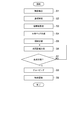
- FIG. 2 is a flowchart showing the operation of the object recognition apparatus 10.
- the sensor input unit 1 detects an object existing in the peripheral area of the host vehicle (step S ⁇ b> 1). More specifically, the laser beam transmitter 11 transmits a laser beam to the surrounding area of the host vehicle, and the reflected light receiving unit 12 receives the reflected light. To detect.
- the coordinate specifying unit 2 specifies the coordinates of the laser light reflection point (step S2).
- the reliability setting unit 3 sets the object presence reliability indicating the reliability of whether or not an object exists in the peripheral area of the host vehicle (step S3). The setting of the object presence reliability by the reliability setting unit 3 will be specifically described.
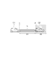
- the reliability setting unit 3 sets the object existence reliability in the area A1 between the sensor input unit 1 and the reflection point P to be lower than the object existence reliability at the reflection point P. It should be noted that an area where no laser light can be reflected can be set as “no object”.
- the distribution map creation unit 4 creates a distribution map of object presence reliability in the peripheral area of the host vehicle based on the object presence reliability set by the reliability setting unit 3 (step S4).
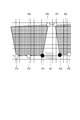
- FIG. 4 is a diagram illustrating an example of a distribution map created by the distribution map creation unit 4.
- the distribution map creation unit 4 is configured such that when the laser beam transmitter 11 transmits a plurality of laser beams two-dimensionally, that is, the reflection spot is two-dimensional in the peripheral area A of the host vehicle C1.
- a two-dimensional map is created when it is placed on the screen.
- the color is set to be darker in the region where the object presence reliability is higher.
- the reliability setting unit 3 sets the object existence reliability in the area A1 between the sensor input unit 1 and the reflection point P of the host vehicle C1 to “no object”, and the object existence at the reflection point P
- the reliability is set as “object present”, and the object presence reliability in the area A2 beyond the reflection point P is set as “unknown”.
- the distribution map reflects the object existence reliability. For this reason, in the distribution map, the color is set dark in the order of the area corresponding to the area A1, the area corresponding to the area A2, and the area corresponding to the reflection point P.
- the region dividing unit 5 divides the distribution map created by the distribution map creating unit 4 into a plurality of regions (step S5). More specifically, as shown in FIG. 4, the distribution map is divided into, for example, a region R1, a region R2, and a region R3. In the distribution map, this corresponds to setting a continuous portion having an object presence reliability equal to or higher than a predetermined threshold as a single region. In this way, by dividing the distribution map into a plurality of regions in advance, it is possible to avoid performing point-to-point distance calculations and shape estimations described later between regions that clearly show different objects. It becomes possible.
- the point-to-point distance measurement unit 6 measures a point-to-point distance indicating a distance between two adjacent reflection points based on the coordinates of the reflection points specified by the coordinate specifying unit 2 (step S6).
- the measurement of the distance between points will be described more specifically.
- FIG. 5 is a diagram illustrating an example of a distribution map created by the distribution map creation unit 4. This distribution map is divided into grids with a predetermined interval. In this distribution map, regions R4 and R5 set in gray are regions where the object existence reliability is “unknown”, and other regions R6 have an object existence reliability of “no object”. It is a certain area. In this distribution map, reflection points P1 to P7 are arranged.
- the inter-point distance measuring unit 6 measures the inter-point distance between two adjacent reflection points in this distribution map, for example. More specifically, for example, the distance between the points between the reflection point P1 and the reflection point P2 and the point-to-point distance between the reflection point P2 and the reflection point P3 are sequentially measured. A region R6 in which the object existence reliability is “no object” is set between the reflection point P3 and the reflection point P4. For this reason, the inter-point distance measuring unit 6 measures the inter-point distance between the reflection point P3 and the reflection point P4 as the distance of the route B passing through the reflection point P6 and the reflection point P7 while following the region R4 and the region R5. . For this reason, the point-to-point distance between the reflection point P3 and the reflection point P4 is measured longer than the actual distance D.
- the point-to-point distance measurement unit 6 measures the point-to-point distance between the two reflection points based on (in consideration of) the object existence reliability in the area between the two reflection points adjacent to each other. More specifically, the point-to-point distance measurement unit 6 considers that no object exists in an area where the object reliability in the distribution map is less than a predetermined threshold (for example, the object reliability indicating “unknown”), and The distance between the two reflection points is measured. For example, an A * search algorithm can be used for measuring the distance between points.
- the object recognition device 10 determines whether or not the measurement of the distance between the points has been performed for all the reflection points (step S7). As a result of this determination, when the measurement of the distance between points has not been performed for all reflection points, the processing of the object recognition device 10 proceeds to step S6.
- the grouping unit 7 groups the reflection points (step S8).
- This grouping can be performed based on the point-to-point distance measured by the point-to-point distance measuring unit 6. That is, this grouping can be performed on the basis that the distance between points is equal to or less than a predetermined distance.
- the reflection points P1 to P3 have a single point G1 because the distance between the points is small. Also, the reflection point P4 and the reflection point P5 are set to a single group G2 because the distance between the points is small. On the other hand, the reflection point P3 and the reflection point P4 are not made into a single group because the distance between the points is measured as the distance of the route B and the distance between the points is not large.
- the object recognizing unit 8 estimates the shape of the object corresponding to the grouped reflection point based on the coordinates of the reflection point grouped by the grouping unit 7, and based on the estimated shape, Recognize (step S9).
- the reliability setting unit 3 sets the object presence reliability indicating the reliability of whether or not an object exists in the peripheral area of the host vehicle. Then, the grouping unit 7 groups the reflection points based on the object existence reliability in the area between the reflection points. More specifically, the grouping unit 7 groups reflection points based on the point-to-point distance measured by the point-to-point distance measurement unit 6 in consideration of the object reliability in the area between the reflection points.
- the reflection point of the two objects is It becomes possible to group them as separate groups instead of a single group. As a result, it is possible to avoid erroneously recognizing a plurality of objects as a single object, thereby improving the object recognition accuracy.
- the reliability setting unit 3 sets the object presence reliability in the area between the sensor input unit 1 and the reflection point to be lower than the object presence reliability at the reflection point. For this reason, the accuracy of setting the object presence reliability is improved.
- the distribution map creation unit 4 creates a distribution map of the object presence reliability in the surrounding area of the vehicle based on the object confidence existence reliability set by the reliability setting unit 3.
- the grouping unit 7 performs grouping based on the distribution map created by the distribution map creating unit 4. More specifically, the grouping unit 7 performs grouping based on the inter-point distance measured by the inter-point distance measuring unit 6 in the distribution map. For this reason, it is possible to easily and reliably group reflection points using a distribution map.
- the grouping unit 7 performs grouping on the assumption that no object exists in an area where the object presence reliability in the distribution map is less than a predetermined threshold. More specifically, the grouping unit 7 performs grouping based on the point-to-point distance measured by the point-to-point distance measuring unit 6 on the assumption that no object exists in an area where the object reliability in the distribution map is less than a predetermined threshold. Do. For this reason, erroneous recognition of a plurality of objects as a single object can be surely avoided, and as a result, the recognition accuracy of the objects can be further improved.
- the object recognition unit 8 estimates the shape of the object in an area where the object presence reliability is a predetermined threshold or more based on the coordinates of the reflection points grouped by the grouping unit 7. For this reason, recognition of an object can be performed accurately based on the estimated shape.
- the above embodiment describes one embodiment of the object recognition apparatus according to one aspect of the present invention, and the object recognition apparatus according to one aspect of the present invention is limited to the object recognition apparatus 10 described above. is not.
- the object recognition device according to one aspect of the present invention can be obtained by arbitrarily modifying the object recognition device 10 without changing the gist of each claim.
- the measurement of the point-to-point distance in the point-to-point distance measuring unit 6 can be performed as follows. That is, as shown in FIG. 6, when there is a region R7 whose object existence reliability is “no object” between the reflection point P3 and the reflection point P4, the distance between the reflection point P3 and the reflection point P4. The distance may not be measured (for example, an invalid value is set). In this case, it is possible to reduce the processing load for obtaining the distance between points.
- the object presence reliability may be a continuous value instead of the three discontinuous values of “no object”, “with object”, and “unknown” as described above.
- LIDAR can be used as the sensor input unit 1. Since LIDAR has a much higher two-dimensional coordinate grasping capability than conventional laser radars, if LIDAR is used as the sensor input unit 1, object recognition can be performed with higher accuracy.
- the object recognition device 10 may be configured not to include the area dividing unit 5. In this case, it is possible to recognize an accurate object with a simple configuration.
- SYMBOLS 1 Sensor input part (object detection part), 2 ... Coordinate specification part (coordinate specification part), 3 ... Reliability setting part (reliability setting part), 4 ... Distribution map creation part (distribution map creation part), 7 ... Grouping unit (grouping unit), 8... Object recognition unit (shape estimation unit), 10... Object recognition device, 11...
Landscapes
- Physics & Mathematics (AREA)
- General Physics & Mathematics (AREA)
- Engineering & Computer Science (AREA)
- Multimedia (AREA)
- Theoretical Computer Science (AREA)
- Traffic Control Systems (AREA)
- Optical Radar Systems And Details Thereof (AREA)
Abstract
Description
Claims (7)
- 車両に搭載された物体認識装置であって、
前記車両の周辺エリアに存在する物体を検出する物体検出部と、
前記物体検出部による物体の検出地点の座標を特定する座標特定部と、
前記座標特定部が特定した前記検出地点の座標に基づいて、物体が存在するか否かの信頼度を示す物体存在信頼度を前記周辺エリアに設定する信頼度設定部と、
前記検出地点同士の間のエリアにおける前記物体存在信頼度に基づいて、前記検出地点をグルーピングするグルーピング部と、
を備える物体認識装置。 - 前記信頼度設定部は、前記物体検出部と前記検出地点との間のエリアにおける前記物体存在信頼度を、前記検出地点における前記物体存在信頼度よりも低く設定する、請求項1に記載の物体認識装置。
- 前記信頼度設定部が設定した前記物体存在信頼度に基づいて、前記周辺エリアにおける前記物体存在信頼度の分布マップを作成する分布マップ作成部をさらに備え、
前記グルーピング部は、前記分布マップ作成部が作成した前記分布マップに基づいて前記グルーピングを行う、請求項1又は2に記載の物体認識装置。 - 前記グルーピング部は、前記分布マップにおける前記物体存在信頼度が所定の閾値未満である領域には、物体が存在しないとみなして前記グルーピングを行う、請求項3に記載の物体認識装置。
- 前記グルーピング部によってグルーピングされた前記検出地点の座標に基づいて、前記物体存在信頼度が所定の閾値以上のエリアにおいて物体の形状を推定する形状推定部をさらに備える、請求項1~4のいずれか一項に記載の物体認識装置。
- 前記物体検出部は、前記周辺エリアにレーザ光を発信する発信部と、前記発信部から発信された前記レーザ光の反射光を受信する受信部とを有し、
前記検出地点は、前記レーザ光の反射地点である、請求項1~5のいずれか一項に記載の物体認識装置。 - 前記検出地点同士の間のエリアにおける前記物体存在信頼度に基づいて、互いに隣り合う2つの前記検出地点の間の点間距離を計測する点間距離計測部をさらに備え、
前記グルーピング部は、前記点間距離が所定の距離以下である前記検出地点を単一のグループとしてグルーピングする、請求項1~6のいずれか一項に記載の物体認識装置。
Priority Applications (4)
| Application Number | Priority Date | Filing Date | Title |
|---|---|---|---|
| CN201280010324.2A CN103443838B (zh) | 2011-03-28 | 2012-03-27 | 物体识别装置 |
| DE112012001506.1T DE112012001506B4 (de) | 2011-03-28 | 2012-03-27 | Objekterkennungsvorrichtung |
| US14/005,128 US9792510B2 (en) | 2011-03-28 | 2012-03-27 | Object recognition device |
| US15/702,177 US10614322B2 (en) | 2011-03-28 | 2017-09-12 | Object recognition device |
Applications Claiming Priority (2)
| Application Number | Priority Date | Filing Date | Title |
|---|---|---|---|
| JP2011069999A JP5316572B2 (ja) | 2011-03-28 | 2011-03-28 | 物体認識装置 |
| JP2011-069999 | 2011-03-28 |
Related Child Applications (2)
| Application Number | Title | Priority Date | Filing Date |
|---|---|---|---|
| US14/005,128 A-371-Of-International US9792510B2 (en) | 2011-03-28 | 2012-03-27 | Object recognition device |
| US15/702,177 Continuation US10614322B2 (en) | 2011-03-28 | 2017-09-12 | Object recognition device |
Publications (1)
| Publication Number | Publication Date |
|---|---|
| WO2012133457A1 true WO2012133457A1 (ja) | 2012-10-04 |
Family
ID=46931169
Family Applications (1)
| Application Number | Title | Priority Date | Filing Date |
|---|---|---|---|
| PCT/JP2012/058007 Ceased WO2012133457A1 (ja) | 2011-03-28 | 2012-03-27 | 物体認識装置 |
Country Status (5)
| Country | Link |
|---|---|
| US (2) | US9792510B2 (ja) |
| JP (1) | JP5316572B2 (ja) |
| CN (1) | CN103443838B (ja) |
| DE (1) | DE112012001506B4 (ja) |
| WO (1) | WO2012133457A1 (ja) |
Cited By (2)
| Publication number | Priority date | Publication date | Assignee | Title |
|---|---|---|---|---|
| US11205289B2 (en) | 2018-09-07 | 2021-12-21 | Baidu Online Network Technology (Beijing) Co., Ltd. | Method, device and terminal for data augmentation |
| US11276243B2 (en) | 2018-09-07 | 2022-03-15 | Baidu Online Network Technology (Beijing) Co., Ltd. | Traffic simulation method, device and storage medium |
Families Citing this family (10)
| Publication number | Priority date | Publication date | Assignee | Title |
|---|---|---|---|---|
| JP4788798B2 (ja) * | 2009-04-23 | 2011-10-05 | トヨタ自動車株式会社 | 物体検出装置 |
| JP5316572B2 (ja) * | 2011-03-28 | 2013-10-16 | トヨタ自動車株式会社 | 物体認識装置 |
| KR101552074B1 (ko) | 2011-10-03 | 2015-09-09 | 도요타 지도샤(주) | 차량의 운전 지원 시스템 |
| JP6410178B2 (ja) * | 2015-01-08 | 2018-10-24 | パナソニックIpマネジメント株式会社 | 物体検出装置および物体検出方法 |
| WO2017130639A1 (ja) * | 2016-01-28 | 2017-08-03 | 株式会社リコー | 画像処理装置、撮像装置、移動体機器制御システム、画像処理方法、及びプログラム |
| JP6698864B2 (ja) * | 2016-11-08 | 2020-05-27 | 三菱電機株式会社 | 物体検知装置および物体検知方法 |
| KR101934731B1 (ko) * | 2016-11-22 | 2019-01-03 | 엘지전자 주식회사 | 차량용 통신 장치 및 차량 |
| JP6479295B2 (ja) * | 2017-01-18 | 2019-03-06 | 三菱電機株式会社 | 駐車支援装置 |
| WO2018150577A1 (ja) * | 2017-02-20 | 2018-08-23 | 三菱電機株式会社 | 駐車支援装置および駐車支援方法 |
| EP3770637B1 (en) * | 2018-03-22 | 2024-05-08 | Hitachi Astemo, Ltd. | Object recognizing device |
Citations (4)
| Publication number | Priority date | Publication date | Assignee | Title |
|---|---|---|---|---|
| JP2002157697A (ja) * | 2000-11-21 | 2002-05-31 | Mazda Motor Corp | 車両の制御装置 |
| JP2003255047A (ja) * | 2001-12-27 | 2003-09-10 | Nissan Motor Co Ltd | 前方物体検出装置及び前方物体検出方法 |
| JP2009176091A (ja) * | 2008-01-25 | 2009-08-06 | Fuji Heavy Ind Ltd | 物体検出装置 |
| JP2009186301A (ja) * | 2008-02-06 | 2009-08-20 | Mazda Motor Corp | 車両用物体検出装置 |
Family Cites Families (23)
| Publication number | Priority date | Publication date | Assignee | Title |
|---|---|---|---|---|
| US6324489B1 (en) * | 1999-10-29 | 2001-11-27 | Safegate International Ab | Aircraft identification and docking guidance systems |
| JP3470453B2 (ja) * | 1995-04-06 | 2003-11-25 | 株式会社デンソー | 車間距離制御装置 |
| JP3405327B2 (ja) | 2000-07-28 | 2003-05-12 | 株式会社デンソー | 物体認識方法及び装置、記録媒体 |
| DE10148070A1 (de) | 2001-09-28 | 2003-04-17 | Ibeo Automobile Sensor Gmbh | Verfahren zur Erkennung und Verfolgung von Objekten |
| AU2003277240A1 (en) * | 2002-10-15 | 2004-06-07 | University Of Southern California | Augmented virtual environments |
| JP2008026997A (ja) | 2006-07-18 | 2008-02-07 | Denso Corp | 歩行者認識装置及び歩行者認識方法 |
| US20080144885A1 (en) * | 2006-10-16 | 2008-06-19 | Mark Zucherman | Threat Detection Based on Radiation Contrast |
| WO2008088584A1 (en) | 2007-01-19 | 2008-07-24 | Agilix Labs, Inc. | Shadow course hierarchy for online courses |
| DE102007013023B4 (de) | 2007-03-19 | 2017-10-05 | Sick Ag | Probabilistische Rasterkarte |
| US8605947B2 (en) * | 2008-04-24 | 2013-12-10 | GM Global Technology Operations LLC | Method for detecting a clear path of travel for a vehicle enhanced by object detection |
| US8705792B2 (en) * | 2008-08-06 | 2014-04-22 | Toyota Motor Engineering & Manufacturing North America, Inc. | Object tracking using linear features |
| JP4944849B2 (ja) | 2008-08-07 | 2012-06-06 | シャープ株式会社 | 磁界および近接場発生素子、その使用方法、光アシスト磁気記録方法、並びに、光アシスト磁気記録装置 |
| DE102008042825A1 (de) * | 2008-10-14 | 2010-04-15 | Robert Bosch Gmbh | Fahrerassistenzsystem für Kraftfahrzeuge |
| JP5392700B2 (ja) | 2008-10-15 | 2014-01-22 | 鹿島建設株式会社 | 障害物検出装置、及び障害物検出方法 |
| DE102009009047A1 (de) * | 2009-02-16 | 2010-08-19 | Daimler Ag | Verfahren zur Objektdetektion |
| JP5293253B2 (ja) | 2009-02-19 | 2013-09-18 | 日産自動車株式会社 | 周囲物体検出装置及び周囲物体検出方法 |
| US20130176192A1 (en) * | 2011-09-30 | 2013-07-11 | Kenneth Varga | Extra-sensory perception sharing force capability and unknown terrain identification system |
| JP4939564B2 (ja) * | 2009-03-23 | 2012-05-30 | 本田技研工業株式会社 | 車両用情報提供装置 |
| JP5316572B2 (ja) * | 2011-03-28 | 2013-10-16 | トヨタ自動車株式会社 | 物体認識装置 |
| US9139133B2 (en) * | 2012-05-31 | 2015-09-22 | GM Global Technology Operations LLC | Vehicle collision warning system and method |
| KR101807484B1 (ko) * | 2012-10-29 | 2017-12-11 | 한국전자통신연구원 | 객체 및 시스템 특성에 기반한 확률 분포 지도 작성 장치 및 그 방법 |
| US10347127B2 (en) * | 2013-02-21 | 2019-07-09 | Waymo Llc | Driving mode adjustment |
| US9360554B2 (en) * | 2014-04-11 | 2016-06-07 | Facet Technology Corp. | Methods and apparatus for object detection and identification in a multiple detector lidar array |
-
2011
- 2011-03-28 JP JP2011069999A patent/JP5316572B2/ja active Active
-
2012
- 2012-03-27 US US14/005,128 patent/US9792510B2/en active Active
- 2012-03-27 CN CN201280010324.2A patent/CN103443838B/zh active Active
- 2012-03-27 DE DE112012001506.1T patent/DE112012001506B4/de active Active
- 2012-03-27 WO PCT/JP2012/058007 patent/WO2012133457A1/ja not_active Ceased
-
2017
- 2017-09-12 US US15/702,177 patent/US10614322B2/en active Active
Patent Citations (4)
| Publication number | Priority date | Publication date | Assignee | Title |
|---|---|---|---|---|
| JP2002157697A (ja) * | 2000-11-21 | 2002-05-31 | Mazda Motor Corp | 車両の制御装置 |
| JP2003255047A (ja) * | 2001-12-27 | 2003-09-10 | Nissan Motor Co Ltd | 前方物体検出装置及び前方物体検出方法 |
| JP2009176091A (ja) * | 2008-01-25 | 2009-08-06 | Fuji Heavy Ind Ltd | 物体検出装置 |
| JP2009186301A (ja) * | 2008-02-06 | 2009-08-20 | Mazda Motor Corp | 車両用物体検出装置 |
Cited By (2)
| Publication number | Priority date | Publication date | Assignee | Title |
|---|---|---|---|---|
| US11205289B2 (en) | 2018-09-07 | 2021-12-21 | Baidu Online Network Technology (Beijing) Co., Ltd. | Method, device and terminal for data augmentation |
| US11276243B2 (en) | 2018-09-07 | 2022-03-15 | Baidu Online Network Technology (Beijing) Co., Ltd. | Traffic simulation method, device and storage medium |
Also Published As
| Publication number | Publication date |
|---|---|
| US20140003671A1 (en) | 2014-01-02 |
| JP2012203806A (ja) | 2012-10-22 |
| DE112012001506T5 (de) | 2014-01-16 |
| DE112012001506B4 (de) | 2022-06-15 |
| CN103443838B (zh) | 2015-06-17 |
| US9792510B2 (en) | 2017-10-17 |
| US20180005056A1 (en) | 2018-01-04 |
| CN103443838A (zh) | 2013-12-11 |
| JP5316572B2 (ja) | 2013-10-16 |
| US10614322B2 (en) | 2020-04-07 |
Similar Documents
| Publication | Publication Date | Title |
|---|---|---|
| JP5316572B2 (ja) | 物体認識装置 | |
| KR102302782B1 (ko) | 위치정보 보정 시스템 및 방법 | |
| US10486698B2 (en) | Vehicle cruise control device and cruise control method | |
| JP5316471B2 (ja) | 物体認識装置、及びプログラム | |
| JP2015155878A (ja) | 車両用障害物検出装置 | |
| JP6694067B2 (ja) | 物体検知装置及びそれを備えた車両制御システム | |
| JPWO2011070650A1 (ja) | 物体検出装置及び物体検出方法 | |
| US10527719B2 (en) | Object detection apparatus and object detection method | |
| JP2010185769A (ja) | 物体検出装置 | |
| JP5712900B2 (ja) | 周辺物体検出装置 | |
| JP6413898B2 (ja) | 歩行者判定装置 | |
| JP6442225B2 (ja) | 物体検知装置 | |
| US20210231799A1 (en) | Object detection device, object detection method and program | |
| JP2014092434A (ja) | 物標検出装置、及び、当該装置を用いた接触回避システム | |
| JP2010127835A (ja) | レーダ装置 | |
| WO2014076875A1 (ja) | 物標検出システム、及び、物標検出装置 | |
| JP5436652B1 (ja) | 車両の周辺監視装置及び車両の周辺監視方法 | |
| US11983937B2 (en) | Intersecting road estimation device | |
| JP4850531B2 (ja) | 車載レーダ装置 | |
| JP2018021788A (ja) | 段差検出方法及び段差検出装置 | |
| JP2009031299A (ja) | 周辺監視センサ | |
| WO2023033040A1 (ja) | フレア検出システム、フレア検出装置、フレア検出方法、フレア検出プログラム | |
| JP7311597B2 (ja) | システム、位置検出装置、位置検出方法およびプログラム | |
| KR20210066777A (ko) | 위치정보 보정 시스템 및 방법 | |
| JP2016057176A (ja) | レーザ測距装置 |
Legal Events
| Date | Code | Title | Description |
|---|---|---|---|
| 121 | Ep: the epo has been informed by wipo that ep was designated in this application |
Ref document number: 12764679 Country of ref document: EP Kind code of ref document: A1 |
|
| WWE | Wipo information: entry into national phase |
Ref document number: 14005128 Country of ref document: US |
|
| WWE | Wipo information: entry into national phase |
Ref document number: 1120120015061 Country of ref document: DE Ref document number: 112012001506 Country of ref document: DE |
|
| 122 | Ep: pct application non-entry in european phase |
Ref document number: 12764679 Country of ref document: EP Kind code of ref document: A1 |