WO2012132778A1 - 内視鏡用挿入補助具 - Google Patents
内視鏡用挿入補助具 Download PDFInfo
- Publication number
- WO2012132778A1 WO2012132778A1 PCT/JP2012/055618 JP2012055618W WO2012132778A1 WO 2012132778 A1 WO2012132778 A1 WO 2012132778A1 JP 2012055618 W JP2012055618 W JP 2012055618W WO 2012132778 A1 WO2012132778 A1 WO 2012132778A1
- Authority
- WO
- WIPO (PCT)
- Prior art keywords
- side wall
- endoscope
- guide
- insertion portion
- state
- Prior art date
- Legal status (The legal status is an assumption and is not a legal conclusion. Google has not performed a legal analysis and makes no representation as to the accuracy of the status listed.)
- Ceased
Links
Images


Classifications
-
- A—HUMAN NECESSITIES
- A61—MEDICAL OR VETERINARY SCIENCE; HYGIENE
- A61B—DIAGNOSIS; SURGERY; IDENTIFICATION
- A61B1/00—Instruments for performing medical examinations of the interior of cavities or tubes of the body by visual or photographical inspection, e.g. endoscopes; Illuminating arrangements therefor
- A61B1/00147—Holding or positioning arrangements
- A61B1/00148—Holding or positioning arrangements using anchoring means
-
- A—HUMAN NECESSITIES
- A61—MEDICAL OR VETERINARY SCIENCE; HYGIENE
- A61B—DIAGNOSIS; SURGERY; IDENTIFICATION
- A61B1/00—Instruments for performing medical examinations of the interior of cavities or tubes of the body by visual or photographical inspection, e.g. endoscopes; Illuminating arrangements therefor
- A61B1/00064—Constructional details of the endoscope body
- A61B1/00071—Insertion part of the endoscope body
- A61B1/0008—Insertion part of the endoscope body characterised by distal tip features
- A61B1/00098—Deflecting means for inserted tools
-
- A—HUMAN NECESSITIES
- A61—MEDICAL OR VETERINARY SCIENCE; HYGIENE
- A61B—DIAGNOSIS; SURGERY; IDENTIFICATION
- A61B1/00—Instruments for performing medical examinations of the interior of cavities or tubes of the body by visual or photographical inspection, e.g. endoscopes; Illuminating arrangements therefor
- A61B1/00147—Holding or positioning arrangements
- A61B1/00154—Holding or positioning arrangements using guiding arrangements for insertion
-
- A—HUMAN NECESSITIES
- A61—MEDICAL OR VETERINARY SCIENCE; HYGIENE
- A61B—DIAGNOSIS; SURGERY; IDENTIFICATION
- A61B1/00—Instruments for performing medical examinations of the interior of cavities or tubes of the body by visual or photographical inspection, e.g. endoscopes; Illuminating arrangements therefor
- A61B1/00064—Constructional details of the endoscope body
- A61B1/00071—Insertion part of the endoscope body
- A61B1/0008—Insertion part of the endoscope body characterised by distal tip features
- A61B1/00082—Balloons
-
- E—FIXED CONSTRUCTIONS
- E05—LOCKS; KEYS; WINDOW OR DOOR FITTINGS; SAFES
- E05D—HINGES OR SUSPENSION DEVICES FOR DOORS, WINDOWS OR WINGS
- E05D7/00—Hinges or pivots of special construction
- E05D7/08—Hinges or pivots of special construction for use in suspensions comprising two spigots placed at opposite edges of the wing, especially at the top and the bottom, e.g. trunnions
- E05D7/081—Hinges or pivots of special construction for use in suspensions comprising two spigots placed at opposite edges of the wing, especially at the top and the bottom, e.g. trunnions the pivot axis of the wing being situated near one edge of the wing, especially at the top and bottom, e.g. trunnions
-
- G—PHYSICS
- G02—OPTICS
- G02B—OPTICAL ELEMENTS, SYSTEMS OR APPARATUS
- G02B23/00—Telescopes, e.g. binoculars; Periscopes; Instruments for viewing the inside of hollow bodies; Viewfinders; Optical aiming or sighting devices
- G02B23/24—Instruments or systems for viewing the inside of hollow bodies, e.g. fibrescopes
- G02B23/2476—Non-optical details, e.g. housings, mountings, supports
Definitions
- the present invention relates to an endoscope insertion aid, and more particularly to an endoscope insertion aid used when inserting an insertion portion of an endoscope into a biliary tract or a pancreatic duct.
- ERCP Endscopic Retrograde Cholangio-Pancreatography
- ERCP is a diagnostic method in which a contrast agent is injected into the biliary tract or pancreatic duct using an endoscope, and the portion is photographed by a fluoroscope.
- the contrast agent injection method first, the insertion portion of the endoscope is inserted to the duodenum.
- a cannula (thin tube) is taken out from the forceps port of the insertion part, a cannula is selectively inserted from the duodenal papilla into the biliary tract or pancreatic duct, a contrast medium is injected into the biliary tract or pancreatic duct through the cannula, and the portion is fluoroscopically Shoot with the device.
- a small diameter endoscope generally called a biliary scope or a pancreatoscope
- confirmation of the presence or absence of a stenosis in the biliary tract or a pancreatic duct confirmation of the presence or absence of a stenosis in the biliary tract or a pancreatic duct, a sampling examination of cells and tissues ( Methods of cytology, biopsy), stone removal etc. are also known.
- an insertion aid for endoscope (also referred to as an overtube or a sliding tube) is used in combination.
- an insertion aid for endoscope also referred to as an overtube or a sliding tube
- Patent Document 1 is made of a cylindrical body which is used as a guide by inserting the insertion portion of the endoscope, and the distal end side of the side wall portion of the cylindrical body is the distal end of the insertion portion. It is disclosed that there is provided an opening through which According to the endoscope insertion aid, when the insertion portion of the endoscope is inserted into the body cavity, the insertion portion is bent or bent by inserting the insertion portion in a state of covering the insertion portion with the cylindrical body.
- the insertion portion is inserted by supporting the insertion portion at the edge of the opening portion Can be easily pushed to the deep part in the body cavity.
- Patent Document 2 discloses a balloon provided with an expandable and contractible balloon on the tip side of an opening formed in the side wall of the cylindrical body. According to this endoscope insertion assisting tool, after the insertion portion having the cylindrical body covered as described above is inserted to a desired position in the body cavity, the balloon is expanded and brought into close contact with the inner wall of the body cavity. The opening of the side wall can be held at a desired position (for example, a position facing the duodenal papilla).
- the insertion portion of the endoscope when the distal end of the insertion portion of the endoscope is taken out from the opening and the distal end of the insertion portion is J-shaped and guided to the proximal end (for example, in the biliary tract), the insertion portion is supported by the upper surface of the balloon While being guided, it is said that the insertion portion can be easily pushed forward.
- the present invention has been made in view of such circumstances, and is an endoscope insertion aid that allows the insertion portion of the endoscope to be smoothly and easily derived from the opening portion of the side wall portion of the cylindrical body. It aims at providing a tool.
- an insertion assisting tool for an endoscope comprises: a cylindrical body having an insertion path through which an insertion portion of the endoscope is inserted; and a tip side of a side wall portion of the cylindrical body A side wall opening portion through which the tip end portion of the insertion portion can pass, and a guide surface which is disposed in the insertion path and guides the insertion portion inserted into the insertion path toward the tip end side of the side wall opening portion.
- a guide member having a guide member, wherein the guide member is in an inclined state in which the guide surface is inclined with respect to the axial direction of the cylindrical body and a retracted state in which the guide surface is substantially parallel to the axial direction of the cylindrical body
- the guide surface is capable of guiding the insertion portion to the side wall opening when in the inclining state between the inclining state and the retracted state.
- the guide member for guiding the insertion portion of the endoscope to the side wall opening portion is provided, even a practitioner who is not familiar with the bending operation of the endoscope can smoothly and easily The insert can be led out of the side wall opening.
- the guide surface is configured to be rotatable between the inclined state and the retracted state centering on a support portion axially supported by the side wall portion of the cylindrical body.
- the end on the support portion side of the guide member be disposed on the proximal side of the tip of the side wall opening.
- the support portion is provided in the vicinity of the side wall opening.
- the end on the support portion side of the guide surface is disposed on the tip end side of the cylindrical body (side wall opening), and the end on the opposite side of the support portion side of the guide surface is the proximal end of the cylindrical body It will be arranged on the side.
- an operation means capable of switching the guide surface between the inclined state and the retracted state. According to the present invention, by switching the guide surface between the inclined state and the retracted state by the operation means, the insertion operation of the insertion portion can be easily performed whether the insertion portion is derived from the side wall opening or not derived .
- control device further comprises biasing means for biasing the guide surface in the direction from the any one of the inclined state and the retracted state to the other state, and the operation means comprises the guide surface. It is preferred that the means operate in the opposite direction to the direction in which the means is biased. According to the present invention, by providing the biasing means for biasing to either one of the inclined state and the retracted state, the operation direction for operating the guide member by the operating means may be one, and the trouble of the operation of the guide member Can be reduced.
- an expandable and contractible balloon is disposed on the outer peripheral surface of the cylindrical body which is closer to the tip end than the side wall opening. According to the present invention, the position of the side wall opening can be held in a stable state by inflating the balloon and contacting the wall surface in the body cavity, and the insertion portion derived from the side wall opening can be positioned as expected. It becomes easy to lead.
- the guide member abuts on the inner surface of the side wall portion opposite to the side wall opening portion of the cylindrical body in the inclined state.
- the guide member is a foldable member, and is a movable guide member capable of transitioning between the inclined state and the retracted state according to the pressing force of the insertion portion.
- the insertion portion of the endoscope can be smoothly and easily derived from the opening portion of the side wall portion of the cylindrical body.
- An external view showing an endoscope apparatus to which an insertion support tool according to an embodiment of the present invention is applied The perspective view which shows the front-end
- An explanatory view (side sectional view) used for explaining the operation of the guide valve of the insertion assisting tool An explanatory view (side sectional view) used for explaining the operation of the guide valve of the insertion assisting tool
- FIG. 1 is an external view showing an endoscope apparatus to which an endoscope insertion aid (hereinafter simply referred to as “insertion aid”) 60 according to an embodiment of the present invention is applied.
- the endoscope apparatus mainly includes an endoscope 10 and an insertion aid 60.
- the endoscope 10 includes a hand operation unit 14 and an insertion unit 12 connected to the hand operation unit 14 and inserted into the body.
- a universal cable 16 is connected to the hand operation unit 14, and a light guide (LG) connector (not shown) is provided at the end of the universal cable 16.
- the LG connector is detachably connected to a light source device (not shown), whereby illumination light is sent to an illumination optical system 54 (see FIG. 2) described later.
- an electrical connector is connected to the LG connector, and the electrical connector is detachably coupled to a processor that performs image signal processing and the like.
- the hand operation unit 14 includes an air supply / water supply button 28, a suction button 30, and a shutter button 32 in parallel, and a pair of angle knobs 36, 36.
- the insertion portion 12 is composed of a flexible portion 40, a bending portion 42 and a tip portion 44 sequentially from the hand operation portion 14 side, and the bending portion 42 is remote by turning the angle knobs 36 and 36 of the hand operation portion 14. The bending operation is performed. This allows the tip 44 to be oriented in a desired direction.
- an observation optical system 52 As shown in FIG. 2, an observation optical system 52, an illumination optical system 54, an air / water supply nozzle 56, and a forceps port 58 are provided on the front end surface 45 of the front end portion 44.
- a CCD (not shown) is disposed behind the observation optical system 52, and a signal cable (not shown) is connected to a substrate that supports the CCD.
- the signal cable is inserted into the insertion unit 12, the hand operation unit 14, the universal cable 16 and the like of FIG. 1 and extended to the electrical connector and connected to the processor. Therefore, the observation image captured by the observation optical system 52 is imaged on the light receiving surface of the CCD and converted into an electrical signal, and this electrical signal is output to the processor through the signal cable and converted into a video signal. Ru. Thereby, the observation image is displayed on the monitor connected to the processor.
- An output end of a light guide (not shown) is disposed behind the illumination optical systems 54, 54 in FIG.
- the light guide is inserted into the insertion portion 12, the hand operation portion 14, and the universal cable 16 of FIG. 1, and the incident end is disposed in the LG connector. Therefore, by connecting the LG connector to the light source device, the illumination light emitted from the light source device is transmitted to the illumination optical system 54, 54 through the light guide, and is emitted forward from the illumination optical system 54, 54.
- the air supply / water supply nozzle 56 of FIG. 2 is in communication with a valve (not shown) operated by the air supply / water supply button 28 of FIG. 1, and this valve is the air supply / water supply connector provided on the LG connector. (Not shown).
- the air / water connector (not shown) is connected to the air / water connector, and air and water are supplied. Therefore, by operating the air supply / water supply button 28, air or water can be jetted from the air supply / water supply nozzle 56 toward the observation optical system 52.
- the forceps port 58 of FIG. 2 is in communication with the forceps insertion portion 46 of FIG. 1 via a forceps channel (not shown). Therefore, by inserting a treatment tool such as forceps from the forceps insertion portion 46, the treatment tool can be drawn out from the forceps port 58. Further, the forceps port 58 is in communication with a valve (not shown) operated by the suction button 30, and the valve is further connected to a suction connector (not shown) of the LG connector. Therefore, by connecting suction means (not shown) to the suction connector and operating the valve with the suction button 30, a lesion or the like can be suctioned from the forceps port 58.
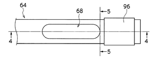
- the insertion assisting tool 60 shown in FIG. 1 includes a grip portion 62 and a tube main body 64.
- the tube main body 64 is formed in a tubular shape, and has an inner diameter larger than the outer diameter of the insertion portion 12 so that the insertion portion 12 of the endoscope 10 can be inserted.
- the tube main body 64 is a flexible urethane resin molded product, the outer peripheral surface thereof is coated with a lubricating coat, and the inner peripheral surface is coated with a lubricating coat.
- a hard grip 62 shown in FIG. 1 is fitted to the tube main body 64 in a watertight state, and the grip 62 is detachably connected to the tube main body 64.
- the insertion portion 12 is inserted toward the tube main body 64 from the proximal end opening 62A of the grip 62.
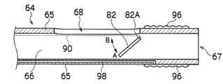
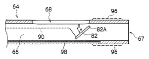
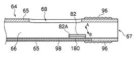
- FIG. 3 to 5 are schematic views showing a configuration example of the vicinity of the tip of the tube main body 64
- FIG. 3 is a plan view
- FIG. 4 is a side sectional view (cross sectional view along line 4-4 in FIG. 3)
- FIG. 5 is a front sectional view (a sectional view taken along line 5-5 in FIG. 3).
- an insertion passage 66 is provided in the inside of the tube main body 64 along the axial direction of the tube main body 64, and the end of the insertion passage 66 at the distal end and proximal end of the tube main body 64.
- An opening to be a part is formed.
- the opening at the tip is referred to as a tip opening 67.
- the insertion path 66 is a conduit through which the insertion portion 12 (see FIG. 1) of the endoscope 10 is inserted, and the cross-sectional shape orthogonal to the axial direction is formed in a substantially circular shape.
- the insertion portion 12 of the endoscope 10 is inserted from the proximal end opening 62A of the grip portion 62 of FIG. 1, the insertion portion 12 enters the insertion path 66 from the opening at the proximal end of the tube main body 64, and the insertion portion 12 as it is.
- the insertion portion 12 can be inserted into the insertion path 66 and led out from the distal end opening 67 of the tube main body 64 as the insertion path 66 is pushed forward.
- An opening 68 (hereinafter referred to as a side wall opening 68) formed of an oblong through hole whose longitudinal direction is the axial direction of the tube main body 64 is provided in the side wall portion 65 on the tip end side of the tube main body 64.
- the side wall opening 68 is a hole having a size through which the insertion portion 12 inserted into the insertion path 66 can pass, and the opening width of the opening 68 (length in a direction perpendicular to the axial direction of the tube main body 64) Is slightly larger than the outer diameter (diameter) of the insertion portion 12 of the endoscope 10, and its length (length in the axial direction of the tube main body 64) is formed sufficiently larger than the opening width.
- the distal end of the insertion portion 12 can be drawn out through the side wall opening 68 of the tube main body 64 by curving the insertion portion 12 inserted into the insertion path 66 of the tube main body 64 as described later. It has become.
- the grip portion 62 is provided with an indicator 86 (see FIG. 1) indicating the direction of the side wall opening 68.
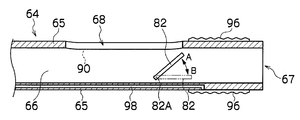
- a guide valve 82 supported so as to be able to pivot in a direction perpendicular to the axial direction of the tube main body 64 at a position near the tip of the side wall opening 68 is provided.
- the guide valve 82 is formed in a plate shape, and as shown in FIG. 5, shaft pins 84, 84 are provided in a projecting manner on both side surfaces on the base end side.
- the shaft pins 84 are pivotally supported by bearing members 88, 88 embedded in the side wall portion 65 of the tube main body 64, and are interposed between the bearing members 88, 88 and the shaft pins 84, 84. For example, it is biased in a predetermined rotational direction by a torsion coil spring.
- the guide valve 82 is provided at a position such that the end on the support shaft 82A side of the guide valve 82 is more proximal to the end on the distal end side of the side wall opening 68.
- the guide valve 82 is supported so as to be pivotable in the AB direction in the figure with the position of the shaft pin 84 as the support shaft 82A (fulcrum), as shown in FIG.
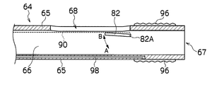
- the inclined state in which the insertion path 66 on the tip end side is closed with respect to the position where the guide valve 82 is provided inclining with respect to the axial direction of the (insertion path 66), and as shown in FIG. It becomes substantially parallel to the axial direction of 66), and makes a transition between a parallel state (retracted state) in which the insertion path 66 on the tip side is closed with respect to the position where the guide valve 82 is provided.
- the guide valve 82 is biased in the A direction, and is held in a tilted state as shown in FIG. 6A unless a pulling force is applied to the guide valve 82 by an operation wire 90 described later.
- the tip end portion of the guide valve 82 abuts on the inner wall surface of the insertion path 66 as shown in FIG. 5, and the further rotation in the A direction is restricted.
- biasing means for biasing the guide valve 82 in a predetermined direction is not limited to the one by the above-mentioned torsion coil spring.
- the guide valve 82 is pulled by the operation wire 90 in the B direction.
- the operation wire 90 is attached by being wound around the shaft pin 84 in a direction in which the winding amount of the operation wire 90 is larger when the guide valve 82 is inclined than when the guide valve 82 is parallel.
- the guide valve 82 is in the tilted state of FIG. 6A, and when the operation wire 90 is pulled to the base end side, the guide valve 82 is in the B direction so that it is in the parallel state of FIG. It is supposed to rotate.
- the operation wire 90 passes through the inside of the wire channel 92 extended along the axial direction (longitudinal direction) in the side wall portion 65 of the tube main body 64 as shown in FIG. Are led out from the wire pipeline 92 into the insertion passage 66 at a position near the guide valve 82 so as to be attached to the shaft pin 84 of the guide valve 82. Further, as shown in FIG. 1, a wire tube 94 having a conduit communicating with the wire conduit 92 is extended, and the proximal end side of the operation wire 90 extends from the proximal end opening of the wire tube 94 It is done.
- the practitioner holds the guide valve 82 in the parallel state as described above by performing an operation of gripping, pulling or relaxing the proximal end side of the operation wire 90 extending from the proximal end opening of the wire tube 94. It is possible to switch between the and the state of inclination.
- the operation wire 90 is pulled to make the guide valve 82 parallel.
- the portion 12 can be inserted up to the tip of the insertion path 66, and the insertion portion 12 can be led out from the tip opening 67.
- the operation wire 90 need not be pulled and may be relaxed.
- the insertion wire 12 is loosened and the guide valve 82 is tilted before the insertion portion 12 passes the position of the guide valve 82, the insertion portion 12 is moved toward the side wall opening 68 by the guide valve 82. Being guided, the insert 12 can be easily led out of the side wall opening 68.
- the insertion portion 12 does not pass through the insertion passage 66 on the tip end side of the guide valve 82 from the gap with the inner wall of the insertion passage 66 (inner surface of the side wall 65 of the tube main body 64) when inclined.
- the size and shape may be sufficient.
- an expandable / contractible balloon 96 is attached to the side wall outer peripheral surface on the tip end side of the side wall opening 68 of the tube main body 64.
- the balloon 96 is in communication with a fluid conduit 98 axially extending in the side wall portion 65 of the tube main body 64, and the fluid conduit 98 extends proximally of the tube main body 64. It is in communication with the conduit in the tube 74 shown in FIG.
- a connector 76 is provided at the end of the tube 74 such that the tube 74 is connected to the balloon controller 78.
- the balloon control device 78 is a device that supplies a fluid such as air to the conduit in the tube 74 connected by the connector 76 and also sucks the fluid from the conduit in the tube 74.
- a fluid such as air
- the fluid supplied to the conduit flows through the fluid conduit 98 of the tube body 64 and is injected into the balloon 96.
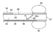
- the balloon 96 to expand annularly around the tube body 64 as shown in FIG.
- the fluid injected into the balloon 96 is discharged from the inside of the balloon 96 to the fluid line 98 of the tube main body 64 by aspirating the fluid from the line in the tube 74 by the balloon control unit 78. And, it flows through the duct in the tube 74 and is aspirated by the balloon controller 78. This causes the balloon 96 to contract.
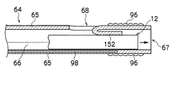
- the insertion assisting tool 60 is put on the insertion portion 12 of the endoscope 10, and as shown in FIG. 8, the insertion portion 12 is inserted into the insertion path 66 of the tube main body 64.
- the insertion portion 12 and the tube main body 64 is inserted from the patient's mouth, and inserted into the duodenum 100 via the stomach while operating the angle knobs 36 and 36 of the endoscope 10 to appropriately bend the bending portion 42.
- the guide valve 82 is made parallel as shown in FIG. 6B, and the insertion portion 12 is advanced into the insertion path 66 on the tip end side of the guide valve 82.
- the tip end of the insertion portion 12 is derived from the position 67.
- the balloon 96 is in a contracted state.
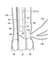
- the balloon control device 78 injects a fluid into the balloon 96 to inflate the balloon 96, thereby bringing the balloon 96 into close contact with the inner wall of the duodenum 100, thereby fixing the position of the tube main body 64 in the duodenum 100.
- the side wall opening 68 of the main body 64 is held at a position facing the duodenal papilla 102.
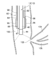
- the insertion portion 12 is pushed forward while curving, and as shown in FIG. 10, the tip of the insertion portion 12 is led out from the side wall opening 68 of the tube main body 64. Insert in 104.
- the insertion portion 12 is guided by the guide valve 82 to easily and smoothly It is derived from the opening 68.
- the distal end side of the insertion portion 12 is bent in a J shape by the bending portion 42 and inserted into the biliary tract 104, the distal end of the insertion portion 12 is guided while the bending portion 42 is supported by the outer surface of the balloon 96. Therefore, the force in the insertion direction works effectively, and the tip of the insertion portion 12 can be easily inserted into the biliary tract 104. After that, the tip of the insertion portion 12 can be gradually pushed to the deep part.
- the endoscope is provided through the side wall opening 68 provided in the side wall 65 of the tube main body 64 easily and smoothly by the guide valve 82 of the tube main body 64
- Ten insertion parts 12 can be derived.
- the insertion portion 12 can be easily inserted into the biliary tract 104 or the pancreatic duct 106 while being supported by the inflated balloon 96.
- the tip end side of the guide valve 82 (the end portion of the guide valve 82 which becomes the tip end side of the tube main body 64) Since the guide valve 82 is held in a tilted state by bringing the proximal end side into contact with the inner wall surface of the tube main body 64, the distal end side is opened on the side wall opening 68 with the proximal end side of the guide valve 82 as a pivot.
- a special lock mechanism or the like for restricting the rotation of the guide valve 82 against the load from the insertion portion 12 and holding in the inclined state, The configuration can be simplified.
- the endoscope 10 is not inserted into the biliary tract 104 or the pancreatic duct 106 from the duodenal papilla 102, but, for example, is held in a state where the distal end surface 45 of the endoscope 10 is brought close to the duodenal papilla 102 during ERCP.
- the cannula is drawn out from the forceps port 58 of the endoscope 10, and a cannula is selectively inserted from the duodenal papilla 102 into the biliary tract 104 and the pancreatic duct 106, and a contrast agent is injected into the biliary duct 104 and the pancreatic duct 106 through the cannula. It is possible.
- the endoscope 10 When the endoscope 10 is inserted from the duodenal papilla 102 into the biliary tract 104 or the pancreatic duct 106 and the inside of the biliary duct 104 or the pancreatic duct 106 is observed, the endoscope 10 is an ultrathin insertion portion not provided with a forceps channel. An endoscope may be used.
- the guide valve 82 of the tube main body 64 was urged
- it may be biased in the opposite direction (direction B) to the above embodiment so as to be in a parallel state.
- the operation wire 90 may be wound and attached in a direction in which the winding amount of the operation wire is larger in the parallel state than when the guide valve 82 is in the tilted state.
- the guide valve 82 becomes parallel as shown in FIG. 6B, and when the operation wire 90 is pulled to the base end side, the guide valve 82 becomes A as shown in FIG. It will turn in the direction.
- the operation wire 90 for pulling the guide valve 82 of the tube main body 64 is attached to the shaft pin 84 of the guide valve 82.
- the present invention is not limited to this.
- the operation wire 90 inserted through the wire pipe extending in the side wall portion 65 of the tube main body 64 is inclined.
- the distal end of the operation wire 90 may be fixed to the distal end portion of the guide valve 82 by being led out into the insertion path 66 from the position on the B direction side with respect to the guide valve 82.
- the parallel to the inclined state is obtained by pushing and pulling the one or a plurality of operation wires. It may be switched by.
- the tube main body 64 (guide valve 82) of the insertion assisting tool 60 will be described.
- components given the same reference numerals as those in the above embodiment have the same or similar functions as or in the same manner as the first embodiment. The components are shown and the description is omitted.
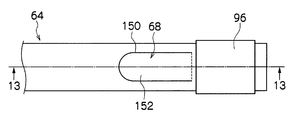
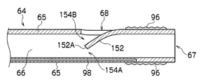
- FIG. 12 and 13 are schematic views showing a configuration example of the vicinity of the tip of the tube main body 64 according to the second embodiment, FIG. 12 is a plan view, and FIG. 13 is a side sectional view (13-13 in FIG. 12). (Cross-sectional view along the line).
- a U-shaped cut 150 is made in the side wall 65 on the distal end side of the tube main body 64, and the portion surrounded by the cut 150 is pushed into the insertion path 66 to guide A valve 152 and a sidewall opening 68 are formed. Further, the guide valve 152 is bent at a portion connected to the cylindrical surface of the tube main body 64, and as shown in FIG. 13, the end 152A of the guide valve 152 (proximal end side of the tube main body 64). The end portion is to be held near the center of the insertion path 66.
- a guide port 154A leading to the distal end opening 67 of the tube main body 64 and a guide port 154B leading to the side wall opening 68 of the tube main body 64 in the insertion passage 66. is formed.
- the guide valve 152 may not be bent toward the distal end side of the tube main body 64 as shown in FIG. 14A, but may be retracted in the direction closing the side wall opening 68.
- the guide valve 152 is further inclined with respect to the axial direction of the tube main body 64 as shown in FIG. 14B by not applying a pressing force more than a predetermined pressure to the guide valve 152, whereby the insertion portion 12 is directed to the side wall opening 68 And is led out of the side wall opening 68.
- an outer peripheral surface near the tip of the insertion portion 12 of the endoscope 10 has, for example, an annular balloon, and the balloon of the insertion portion 12 when the insertion portion 12 is inserted into the guide port 154B.
- the guide valve 152 may be controlled by an operation wire.
- an operation wire For example, as shown in FIG. 15, the tip of the operation wire 160 or the operation wire 162 inserted through the inside of the wire channel axially extended in the side wall of the tube main body 64 So that the guide valve 152 is shown in FIG. 13 with the operation wire 160 or the operation wire 162 relaxed, or in a state substantially parallel to the axial direction of the tube main body 64 (insertion path 66).
- the operation wire 160 or the operation wire 162 When the operation wire 160 or the operation wire 162 is pulled, it may be tilted as shown in FIG. 14B.
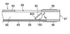
- FIG. 16 is a side sectional view showing a configuration example in the vicinity of the tip end of the tube main body 64 of the third embodiment.
- the position of the support shaft 82A for rotatably supporting the guide valve 82 is on the tip side of the tube main body 64. The difference is that the position is not on the position but on the position on the base end side, and the point that the operation wire 90 is not provided, and the other configuration is the same as that of the first embodiment.
- the guide valve 82 is biased in the direction A in the figure by biasing means such as a torsion coil spring as in the first embodiment, and as shown by the solid line in the figure, with respect to the axial direction of the tube main body 64. It is in a tilted state.
- biasing means such as a torsion coil spring as in the first embodiment, and as shown by the solid line in the figure, with respect to the axial direction of the tube main body 64. It is in a tilted state.
- the guide valve 82 rotates in the B direction with the support shaft 82A as a fulcrum. Then, as shown by the broken line in the figure, the parallel state becomes substantially parallel to the axial direction of the tube main body 64, and the tip of the endoscope 10 travels in the insertion path 66 toward the tip opening 68.
- the insertion portion 12 is led out from the side wall opening portion 68 of the tube main body 64, the insertion portion 12 is inclined by curving the curved portion 42 of the insertion portion 12 to advance toward the side wall opening portion 68. Guided by the guide valve 82 in the state, it is led out of the side wall opening 68.
- the present invention is not limited to the case where a biasing means such as a torsion coil spring is provided to the support means supported by the guide valve 82 as the biasing means of the guide valve 82 according to the first embodiment.
- a spring member 170 may be provided between the guide valve 82 and the side wall portion 65 of the tube main body 64 to bias the guide valve 82 in the A direction.
- one end of the guide valve 82 is directly fixed to the side wall portion 65 of the tube main body 64 so that the guide valve 82 can be installed. It is possible to support and simplify the means for supporting the guide valve 82.
- the guide valve 82 may be rotated in the B direction by the operation wire so that the state can be changed from the inclined state to the parallel state (retracted state).
- the guide valve 82 may be biased in the B direction by a predetermined biasing means, and the guide valve 82 may be rotated in the A direction by the operation wire.
- the desired direction of the guide valve 82 in the A direction and B direction by the operation wire etc. may be rotated.
- FIG. 18A there is also a method of placing an expandable balloon 180 between the guide valve 82 and the side wall portion 65 of the tube main body 64. According to this, by injecting a fluid such as air into the balloon 180, the guide valve 82 is tilted as shown in FIG. 18A, and by discharging the fluid from the inside of the balloon 180, the guide valve 82 is parallel as shown in FIG. 18B.
- the balloon 180 is in fluid communication with a fluid channel extending along the axial direction in the side wall of the tube main body 64 similarly to the balloon 96, and the fluid channel is connected to the balloon control device, Injection and discharge are performed.
- the biasing means is not incorporated in the support means of the guide valve 82, one end of the guide valve 82 can be directly fixed to the side wall portion 65 of the tube main body 64 to support the guide valve 82.
- the support means of the guide valve 82 can be simplified.
- Forceps Insertion part 52 photographing optical system 58: forceps port 60: insertion aid 62: gripping part 62A: proximal end opening 64: tube main body 66: insertion path 67: tip opening 68: 68 Side wall openings 74: tubes 76: connectors 78: balloon control devices 82: 152 guide valves 82A: support shafts 84: axial pins 86: indicators 88: bearing members 90, 160, 162 ... Operation wire, 92: wire channel, 94: wire tube, 96, 180: balloon, 98: fluid channel, 100: duodenum, 102: duodenal papilla, 104: biliary tract, 106: pancreatic duct
Landscapes
- Health & Medical Sciences (AREA)
- Life Sciences & Earth Sciences (AREA)
- Surgery (AREA)
- Biomedical Technology (AREA)
- Medical Informatics (AREA)
- Optics & Photonics (AREA)
- Pathology (AREA)
- Radiology & Medical Imaging (AREA)
- Biophysics (AREA)
- Engineering & Computer Science (AREA)
- Physics & Mathematics (AREA)
- Heart & Thoracic Surgery (AREA)
- Nuclear Medicine, Radiotherapy & Molecular Imaging (AREA)
- Molecular Biology (AREA)
- Animal Behavior & Ethology (AREA)
- General Health & Medical Sciences (AREA)
- Public Health (AREA)
- Veterinary Medicine (AREA)
- Endoscopes (AREA)
- Instruments For Viewing The Inside Of Hollow Bodies (AREA)
Priority Applications (4)
| Application Number | Priority Date | Filing Date | Title |
|---|---|---|---|
| EP12763908.6A EP2692273B1 (en) | 2011-03-31 | 2012-03-06 | Endoscope insertion assitive device |
| EP18205759.6A EP3461391B1 (en) | 2011-03-31 | 2012-03-06 | Insertion assisting tool for endoscope |
| US14/039,902 US9986897B2 (en) | 2011-03-31 | 2013-09-27 | Insertion assisting tool for endoscope |
| US15/969,404 US10441143B2 (en) | 2011-03-31 | 2018-05-02 | Insertion assisting tool for endoscope |
Applications Claiming Priority (2)
| Application Number | Priority Date | Filing Date | Title |
|---|---|---|---|
| JP2011079218A JP5663373B2 (ja) | 2011-03-31 | 2011-03-31 | 内視鏡用挿入補助具 |
| JP2011-079218 | 2011-03-31 |
Related Child Applications (1)
| Application Number | Title | Priority Date | Filing Date |
|---|---|---|---|
| US14/039,902 Continuation US9986897B2 (en) | 2011-03-31 | 2013-09-27 | Insertion assisting tool for endoscope |
Publications (1)
| Publication Number | Publication Date |
|---|---|
| WO2012132778A1 true WO2012132778A1 (ja) | 2012-10-04 |
Family
ID=46930525
Family Applications (1)
| Application Number | Title | Priority Date | Filing Date |
|---|---|---|---|
| PCT/JP2012/055618 Ceased WO2012132778A1 (ja) | 2011-03-31 | 2012-03-06 | 内視鏡用挿入補助具 |
Country Status (4)
| Country | Link |
|---|---|
| US (2) | US9986897B2 (enExample) |
| EP (2) | EP2692273B1 (enExample) |
| JP (1) | JP5663373B2 (enExample) |
| WO (1) | WO2012132778A1 (enExample) |
Cited By (1)
| Publication number | Priority date | Publication date | Assignee | Title |
|---|---|---|---|---|
| US20140235943A1 (en) * | 2013-02-15 | 2014-08-21 | Intuitive Surgical Operations, Inc. | Vision Probe with Access Port |
Families Citing this family (18)
| Publication number | Priority date | Publication date | Assignee | Title |
|---|---|---|---|---|
| JP5752740B2 (ja) * | 2013-05-15 | 2015-07-22 | 富士システムズ株式会社 | 内視鏡用スライディングチューブ |
| JP6210908B2 (ja) * | 2014-03-17 | 2017-10-11 | オリンパス株式会社 | チューブ体及び内視鏡システム |
| US11234581B2 (en) * | 2014-05-02 | 2022-02-01 | Endochoice, Inc. | Elevator for directing medical tool |
| JP6351843B2 (ja) * | 2014-06-25 | 2018-07-04 | マッカイ メモリアル ホスピタルMackay Memorial Hospital | 超薄型内視鏡補助システム |
| US9913570B2 (en) | 2015-08-07 | 2018-03-13 | Enlightenvue Llc | Endoscope with variable profile tip |
| CN111065329A (zh) | 2017-06-30 | 2020-04-24 | 茵莱特恩视觉有限责任公司 | 内窥镜系统及其使用方法 |
| CN107714142A (zh) * | 2017-11-11 | 2018-02-23 | 宋勇 | 一种便携式胆道镜 |
| US10687698B2 (en) | 2018-09-12 | 2020-06-23 | Enlightenvue Llc | Direct endoluminal- and/or endovascular-illumination systems and methods of use thereof |
| US11883048B2 (en) * | 2018-12-07 | 2024-01-30 | Acclarent, Inc. | Instrument with integral imaging and irrigation features |
| US11925333B2 (en) | 2019-02-01 | 2024-03-12 | Covidien Lp | System for fluoroscopic tracking of a catheter to update the relative position of a target and the catheter in a 3D model of a luminal network |
| EP4631416A2 (en) | 2019-04-23 | 2025-10-15 | Boston Scientific Scimed, Inc. | Modular scope device |
| JP7419407B2 (ja) * | 2019-06-28 | 2024-01-22 | 南▲微▼医学科技股▲フン▼有限公司 | オーバーチューブ装置および内視鏡アッセンブリ |
| US11786113B2 (en) * | 2020-01-07 | 2023-10-17 | Gyrus Acmi, Inc. | Endoscope with low-profile distal section |
| EP4117500A1 (en) * | 2020-03-10 | 2023-01-18 | Boston Scientific Scimed Inc. | Devices, systems, and methods for an instrument accessory |
| US20220280135A1 (en) * | 2021-03-04 | 2022-09-08 | Covidien Lp | Endoscope or catheter assemblies including two or more exit ports |
| WO2022187705A1 (en) * | 2021-03-04 | 2022-09-09 | Covidien Lp | Endoscope or catheter assemblies including two or more exit ports |
| CN114557733B (zh) * | 2022-02-28 | 2023-03-21 | 常州市久虹医疗器械有限公司 | 一种内窥镜用活检阀 |
| CN119791565B (zh) * | 2025-03-14 | 2025-06-13 | 湖南省华芯医疗器械有限公司 | 一种涡流组件、插入部及内窥镜 |
Citations (5)
| Publication number | Priority date | Publication date | Assignee | Title |
|---|---|---|---|---|
| JPS60185532A (ja) | 1984-03-05 | 1985-09-21 | オリンパス光学工業株式会社 | 内視鏡用挿入補助具 |
| JPS6222623A (ja) | 1985-07-24 | 1987-01-30 | オリンパス光学工業株式会社 | 内視鏡用插入補助具 |
| JPS62292135A (ja) * | 1986-06-12 | 1987-12-18 | オリンパス光学工業株式会社 | 内視鏡用挿入補助具 |
| JP2010253234A (ja) * | 2009-03-09 | 2010-11-11 | Fujifilm Corp | 側視内視鏡装置 |
| JP2011131047A (ja) * | 2009-11-28 | 2011-07-07 | Kinya Fujita | 内視鏡誘導用管状部材 |
Family Cites Families (18)
| Publication number | Priority date | Publication date | Assignee | Title |
|---|---|---|---|---|
| US4224929A (en) * | 1977-11-08 | 1980-09-30 | Olympus Optical Co., Ltd. | Endoscope with expansible cuff member and operation section |
| JPS62102731A (ja) * | 1985-10-30 | 1987-05-13 | オリンパス光学工業株式会社 | 内視鏡用案内管 |
| DE3621509A1 (de) * | 1986-06-27 | 1988-03-03 | Wolf Gmbh Richard | Seitenblick-endoskop |
| US5152277A (en) * | 1987-07-23 | 1992-10-06 | Terumo Kabushiki Kaisha | Catheter tube |
| US4982724A (en) * | 1987-12-28 | 1991-01-08 | Olympus Opicals Co. | Endoscope apparatus |
| US5460168A (en) * | 1992-12-25 | 1995-10-24 | Olympus Optical Co., Ltd. | Endoscope cover assembly and cover-system endoscope |
| JP4533695B2 (ja) * | 2003-09-23 | 2010-09-01 | オリンパス株式会社 | 処置用内視鏡 |
| DE10358817B3 (de) * | 2003-12-16 | 2005-04-14 | Olympus Winter & Ibe Gmbh | Endoskop |
| JP4025755B2 (ja) * | 2004-07-02 | 2007-12-26 | オリンパス株式会社 | 内視鏡 |
| KR100865834B1 (ko) * | 2004-10-05 | 2008-10-28 | 올림푸스 가부시키가이샤 | 내시경 시스템 및 생체 시료 수용 용기 |
| JP4921774B2 (ja) * | 2005-11-08 | 2012-04-25 | オリンパス株式会社 | 内視鏡用照明具及び内視鏡装置 |
| WO2007063904A1 (ja) * | 2005-12-01 | 2007-06-07 | Olympus Medical Systems Corp. | ガイド用細長医療部材、及び細長医療装置 |
| JP4884046B2 (ja) * | 2006-03-22 | 2012-02-22 | 富士フイルム株式会社 | 超音波内視鏡 |
| US8002698B2 (en) * | 2007-04-04 | 2011-08-23 | Olympus Medical Systems Corp. | Therapeutic method that uses overtube |
| JP4642936B2 (ja) * | 2009-02-09 | 2011-03-02 | オリンパスメディカルシステムズ株式会社 | 医療用チューブ |
| JP5487745B2 (ja) * | 2009-06-12 | 2014-05-07 | 横浜ゴム株式会社 | 扉開閉装置 |
| JP5491084B2 (ja) * | 2009-07-01 | 2014-05-14 | 幹人 黒田 | 内視鏡装置 |
| JP5437300B2 (ja) * | 2011-03-17 | 2014-03-12 | 富士フイルム株式会社 | 内視鏡用挿入補助具 |
-
2011
- 2011-03-31 JP JP2011079218A patent/JP5663373B2/ja active Active
-
2012
- 2012-03-06 WO PCT/JP2012/055618 patent/WO2012132778A1/ja not_active Ceased
- 2012-03-06 EP EP12763908.6A patent/EP2692273B1/en not_active Not-in-force
- 2012-03-06 EP EP18205759.6A patent/EP3461391B1/en not_active Not-in-force
-
2013
- 2013-09-27 US US14/039,902 patent/US9986897B2/en active Active
-
2018
- 2018-05-02 US US15/969,404 patent/US10441143B2/en active Active
Patent Citations (5)
| Publication number | Priority date | Publication date | Assignee | Title |
|---|---|---|---|---|
| JPS60185532A (ja) | 1984-03-05 | 1985-09-21 | オリンパス光学工業株式会社 | 内視鏡用挿入補助具 |
| JPS6222623A (ja) | 1985-07-24 | 1987-01-30 | オリンパス光学工業株式会社 | 内視鏡用插入補助具 |
| JPS62292135A (ja) * | 1986-06-12 | 1987-12-18 | オリンパス光学工業株式会社 | 内視鏡用挿入補助具 |
| JP2010253234A (ja) * | 2009-03-09 | 2010-11-11 | Fujifilm Corp | 側視内視鏡装置 |
| JP2011131047A (ja) * | 2009-11-28 | 2011-07-07 | Kinya Fujita | 内視鏡誘導用管状部材 |
Non-Patent Citations (1)
| Title |
|---|
| See also references of EP2692273A4 |
Cited By (2)
| Publication number | Priority date | Publication date | Assignee | Title |
|---|---|---|---|---|
| US20140235943A1 (en) * | 2013-02-15 | 2014-08-21 | Intuitive Surgical Operations, Inc. | Vision Probe with Access Port |
| US11172809B2 (en) * | 2013-02-15 | 2021-11-16 | Intuitive Surgical Operations, Inc. | Vision probe with access port |
Also Published As
| Publication number | Publication date |
|---|---|
| US20180249897A1 (en) | 2018-09-06 |
| EP2692273B1 (en) | 2018-12-05 |
| JP2012213435A (ja) | 2012-11-08 |
| JP5663373B2 (ja) | 2015-02-04 |
| US10441143B2 (en) | 2019-10-15 |
| EP3461391B1 (en) | 2020-04-22 |
| US20140024897A1 (en) | 2014-01-23 |
| US9986897B2 (en) | 2018-06-05 |
| EP3461391A1 (en) | 2019-04-03 |
| EP2692273A4 (en) | 2014-08-20 |
| EP2692273A1 (en) | 2014-02-05 |
Similar Documents
| Publication | Publication Date | Title |
|---|---|---|
| JP5663373B2 (ja) | 内視鏡用挿入補助具 | |
| JP5437300B2 (ja) | 内視鏡用挿入補助具 | |
| JP5231258B2 (ja) | 改良型カテーテルを有する内視鏡装置 | |
| JP4025755B2 (ja) | 内視鏡 | |
| JP5327986B2 (ja) | 内視鏡用挿入補助具 | |
| JP5001082B2 (ja) | 内視鏡装置 | |
| US20070208220A1 (en) | Endoscopic delivery apparatus having a catheter with radial grooves | |
| US20190365206A1 (en) | Guide wire gripping unit | |
| JP2009539506A (ja) | 拡大可能なバルーン送達システムを有する内視鏡器具 | |
| JP5496140B2 (ja) | 内視鏡用挿入補助具 | |
| JP2001275942A (ja) | 内視鏡固定具 | |
| JP2024161175A (ja) | 内視鏡ツール安定化、及び関連の使用方法 | |
| JP4414827B2 (ja) | 内視鏡 | |
| JP5498422B2 (ja) | 内視鏡用挿入補助具 | |
| JP5253546B2 (ja) | 内視鏡用挿入補助具 | |
| JP5030449B2 (ja) | 内視鏡挿入補助具 | |
| US20250169880A1 (en) | Endoscopic treatment tool and endoscopic treatment system | |
| JP2005230087A (ja) | オーバチューブ | |
| JP2008023102A (ja) | 内視鏡 |
Legal Events
| Date | Code | Title | Description |
|---|---|---|---|
| 121 | Ep: the epo has been informed by wipo that ep was designated in this application |
Ref document number: 12763908 Country of ref document: EP Kind code of ref document: A1 |
|
| WWE | Wipo information: entry into national phase |
Ref document number: 2012763908 Country of ref document: EP |
|
| NENP | Non-entry into the national phase |
Ref country code: DE |