EP2692273B1 - Endoscope insertion assitive device - Google Patents
Endoscope insertion assitive device Download PDFInfo
- Publication number
- EP2692273B1 EP2692273B1 EP12763908.6A EP12763908A EP2692273B1 EP 2692273 B1 EP2692273 B1 EP 2692273B1 EP 12763908 A EP12763908 A EP 12763908A EP 2692273 B1 EP2692273 B1 EP 2692273B1
- Authority
- EP
- European Patent Office
- Prior art keywords
- guiding
- tubular body
- opening part
- endoscope
- distal end
- Prior art date
- Legal status (The legal status is an assumption and is not a legal conclusion. Google has not performed a legal analysis and makes no representation as to the accuracy of the status listed.)
- Not-in-force
Links
Images


Classifications
-
- A—HUMAN NECESSITIES
- A61—MEDICAL OR VETERINARY SCIENCE; HYGIENE
- A61B—DIAGNOSIS; SURGERY; IDENTIFICATION
- A61B1/00—Instruments for performing medical examinations of the interior of cavities or tubes of the body by visual or photographical inspection, e.g. endoscopes; Illuminating arrangements therefor
- A61B1/00147—Holding or positioning arrangements
- A61B1/00148—Holding or positioning arrangements using anchoring means
-
- A—HUMAN NECESSITIES
- A61—MEDICAL OR VETERINARY SCIENCE; HYGIENE
- A61B—DIAGNOSIS; SURGERY; IDENTIFICATION
- A61B1/00—Instruments for performing medical examinations of the interior of cavities or tubes of the body by visual or photographical inspection, e.g. endoscopes; Illuminating arrangements therefor
- A61B1/00064—Constructional details of the endoscope body
- A61B1/00071—Insertion part of the endoscope body
- A61B1/0008—Insertion part of the endoscope body characterised by distal tip features
- A61B1/00098—Deflecting means for inserted tools
-
- A—HUMAN NECESSITIES
- A61—MEDICAL OR VETERINARY SCIENCE; HYGIENE
- A61B—DIAGNOSIS; SURGERY; IDENTIFICATION
- A61B1/00—Instruments for performing medical examinations of the interior of cavities or tubes of the body by visual or photographical inspection, e.g. endoscopes; Illuminating arrangements therefor
- A61B1/00147—Holding or positioning arrangements
- A61B1/00154—Holding or positioning arrangements using guiding arrangements for insertion
-
- A—HUMAN NECESSITIES
- A61—MEDICAL OR VETERINARY SCIENCE; HYGIENE
- A61B—DIAGNOSIS; SURGERY; IDENTIFICATION
- A61B1/00—Instruments for performing medical examinations of the interior of cavities or tubes of the body by visual or photographical inspection, e.g. endoscopes; Illuminating arrangements therefor
- A61B1/00064—Constructional details of the endoscope body
- A61B1/00071—Insertion part of the endoscope body
- A61B1/0008—Insertion part of the endoscope body characterised by distal tip features
- A61B1/00082—Balloons
-
- E—FIXED CONSTRUCTIONS
- E05—LOCKS; KEYS; WINDOW OR DOOR FITTINGS; SAFES
- E05D—HINGES OR SUSPENSION DEVICES FOR DOORS, WINDOWS OR WINGS
- E05D7/00—Hinges or pivots of special construction
- E05D7/08—Hinges or pivots of special construction for use in suspensions comprising two spigots placed at opposite edges of the wing, especially at the top and the bottom, e.g. trunnions
- E05D7/081—Hinges or pivots of special construction for use in suspensions comprising two spigots placed at opposite edges of the wing, especially at the top and the bottom, e.g. trunnions the pivot axis of the wing being situated near one edge of the wing, especially at the top and bottom, e.g. trunnions
-
- G—PHYSICS
- G02—OPTICS
- G02B—OPTICAL ELEMENTS, SYSTEMS OR APPARATUS
- G02B23/00—Telescopes, e.g. binoculars; Periscopes; Instruments for viewing the inside of hollow bodies; Viewfinders; Optical aiming or sighting devices
- G02B23/24—Instruments or systems for viewing the inside of hollow bodies, e.g. fibrescopes
- G02B23/2476—Non-optical details, e.g. housings, mountings, supports
Definitions
- the present invention relates to an insertion assisting tool for an endoscope according to the preamble of claim 1, and in particular, relates to an insertion assisting tool for an endoscope used in inserting an insertion part of an endoscope into the biliary tract or the pancreatic duct.
- pancreaticobiliary diseases such as biliary tract cancer, pancreas cancer, cholelithiasis and choledocholithiasis, for example, has been widely spreading in the field of medicine. These have the advantages of being less invasive and imposing less strain on patients than conventional surgical treatment.
- ERCP Endoscopic Retrograde Cholangio-Pancreatography
- the ERCP is a diagnosis method using an endoscope to inject contrast medium into the biliary tract or the pancreatic duct and photograph that portion with a fluoroscope.
- an insertion part of the endoscope is inserted into the duodenum.
- a cannula (thin tube) is fed from a forceps exit of the insertion part, the cannula is inserted from the major duodenal papilla selectively into the biliary tract or the pancreatic duct, a contrast medium is injected into the biliary tract or the pancreatic duct through the cannula, and that portion is photographed with a fluoroscope.
- a method of confirming the presence or absence of a site of stenosis inside the biliary tract or the pancreatic duct, sampling and examining cells or tissues (cytodiagnosis and biopsy), removing calculi, or the like is also known, which is performed by inserting the insertion part of a thin endoscope, generally called cholangioscope or pancreatoscope, into the biliary tract or the pancreatic duct.
- a thin endoscope generally called cholangioscope or pancreatoscope
- an insertion assisting tool for an endoscope also called “overtube” or “sliding tube”
- PTL 1 discloses one including a tubular body used as a guide through which an insertion part of an endoscope is passed, an opening part through which a distal end of the insertion part can be passed, the opening part being provided on a distal end side of a sidewall portion of the tubular body.
- this insertion assisting tool for an endoscope when the insertion part of the endoscope is inserted into a body cavity, it is made possible by performing insertion in a state where the insertion part is covered with the tubular body easily, to perform insertion operation of the insertion part while preventing excessive bending or flexing of the insertion part. Moreover, when the distal end of the insertion part is fed from the opening part of the sidewall portion of the tubular body to be guided into a body cavity (for example, into the biliary tract), the insertion part can be easily put forward into a deep portion in the body cavity by performing the insertion while the insertion part is received and supported on an edge portion of the opening part.
- PTL 2 discloses one including an inflatable and deflatable balloon that is positioned more distally than the opening part formed in the sidewall portion of the tubular body.
- this insertion assisting tool for an endoscope after the insertion part covered with the tubular body as mentioned above, is inserted up to a desired position in the body cavity, by inflating the balloon so as to come into close contact with an inner wall of the body cavity, the opening part of the sidewall portion can be held at a desired position (for example, at a position opposite to the major duodenal papilla).
- the insertion part of the endoscope when the distal end of the insertion part of the endoscope is fed from the opening part and the distal end of the insertion part is made into a J-shape and guided onto a proximal end side of the insertion part (for example, into the biliary tract), since the insertion part is guided while received and supported on an upper face of the balloon, the insertion part can be easily put forward.
- US 2005/090709 A1 discloses an insertion assisting tool for an endoscope, in which the supporting axis of the guiding member is positioned at a location opposing the side wall opening port of the tubular body and the guiding member is urged by a spring into the direction of said opening port.
- the guiding member can be retracted by the manipirulating wire against the resilient force of the spring.
- EP 1 955 643 A1 discloses an insertion assisting tool for an endoscope, in which the guiding member, when being in a retracted state, is received by a recess formed in the sidewall portion opposites the sidewall opening part.
- a free end of the rotatable guiding member can be brought into an inclined state by means of a manipulating wire which is attached to the free end of the guiding member, the end opposite to the free end being connected to sidewalls of said resets in a rotatable manner.
- the present invention has been made in view of these circumstances, and an object of the present invention is to provide an insertion assisting tool for an endoscope capable of allowing an insertion part of an endoscope smoothly and easily to be fed from an opening part of a sidewall portion of a tubular body.
- an insertion assisting tool for an endoscope includes the features of claim 1. Preferred embodiments are defined by the dependent claims.
- the guiding member guiding the insertion part of the endoscope to the sidewall opening part is provided, even an inexperienced operator in bending operation of the endoscope can smoothly and easily feed the insertion part from the sidewall opening part.
- the guiding surface be configured to be rotatable between the inclined state and the retracted state, a supporting part which is supported on the sidewall portion of the tubular body being a center axis.
- an end portion of the guiding member on a side of the supporting part be disposed more proximally than a distal end of the sidewall opening part.
- the supporting part be provided at a position in a vicinity of the sidewall opening part.
- the configuration is such that the end portion of the guiding surface on the supporting part side is disposed on the distal end side of the tubular body (sidewall opening part) and that the end portion of the guiding surface on the side opposite to the supporting part side is disposed on the proximal end side of the tubular body.
- manipulating means capable of switching the guiding surface between the inclined state and the retracted state. According to the present invention, by switching the guiding surface between the inclined state and the retracted state with the manipulating means, insertion operation of the insertion part is easily to be performed in either case where the insertion part is fed or not fed from the sidewall opening part.
- the manipulating means is means for manipulating the guiding surface in a direction opposite to a direction in which the urging means urges the guiding surface.
- the manipulation direction in which the manipulating means manipulates the guiding member may be one direction, enabling to reduce load on manipulation of the guiding member.
- an inflatable and deflatable balloon be disposed on an outer peripheral surface of the tubular body that is positioned more distally than the sidewall opening part. According to the present invention, by inflating the balloon to allow it to come into contact with a wall surface in the body cavity, a position of the sidewall opening part can be held in a stable state, and the insertion part fed from the sidewall opening part can easily be guided to an expected position.
- the guiding member be a foldable member and be a movable guiding member capable of transition between the inclined state and the retracted state in response to pushing force of the insertion part.
- the insertion part of the endoscope can be smoothly and easily fed from the opening part in the sidewall portion of the tubular body.
- FIG 1 is an external view showing an endoscopic device to which an insertion assisting tool for an endoscope (hereinafter simply referred to as "insertion assisting tool") 60 according to an embodiment of the present invention is applied.
- the endoscopic device is mainly composed of an endoscope 10 and the insertion assisting tool 60.
- the endoscope 10 includes a hand operating part 14 and an insertion part 12 that is provided in connection with this hand operating part 14 and inserted into the body.
- the hand operating part 14 is connected to a universal cable 16 and a distal end of this universal cable 16 is provided with a light guide (LG) connector (not shown in the figure).
- the LG connector is attachably and detachably coupled with a light source device (not shown in the figure) by which illumination light is transmitted to an illumination optical system 54 (see Figure 2 ) mentioned later.
- the LG connector is connected to an electric connector and this electric connector is attachably and detachably coupled with a processor performing image signal processing or the like.
- the hand operating part 14 is provided with an air-supply/water-supply button 28, a suction button 30 and a shutter button 32, which are positioned side by side, and also provided with a pair of angle knobs 36, 36.
- the insertion part 12 is composed of a flexible part 40, a bending part 42 and a distal end portion 44 in this order from the hand operating part 14 side, and the bending part 42 remotely undergoes bending operation by rotating the angle knobs 36, 36 of the hand operating part 14. This makes it possible to turn the distal end portion 44 to a desired direction.
- a distal end face 45 of the distal end portion 44 is provided with an observation optical system 52, the illumination optical systems 54, an air-supply/water-supply nozzle 56 and a forceps exit 58.
- a CCD (not shown) is disposed behind the observation optical system 52 and a substrate supporting this CCD is connected to a signal cable (not shown).
- the signal cable is extended to the electrical connector through the insertion part 12, the hand operating part 14, the universal cable 16 and the like in Figure 1 to be connected to the processor. Therefore, an observation image taken by the observation optical system 52 is imaged on a light-receiving surface of the CCD and converted into an electric signal, and then, this electric signal is outputted to the processor via the signal cable and converted into a video signal. Thereby, the observation image is displayed on a monitor connected to the processor.
- a light emission end of a light guide (not shown) is disposed behind the illumination optical systems 54, 54 in Figure 2 .
- This light guide is passed through the insertion part 12, the hand operating part 14 and the universal cable 16 in Figure 1 , and an incident end thereof is disposed in the LG connector. Accordingly, by coupling the LG connector with the light source device, illumination light emitted from the light source device is transmitted to the illumination optical systems 54, 54 via the light guide and emitted forward from the illumination optical systems 54, 54.
- the air-supply/water-supply nozzle 56 in Figure 2 is in communication with a valve (not shown) operated with the air-supply/water-supply button 28 in Figure 1 , and this valve is further in communication with an air-supply/water-supply connector (not shown) provided in the LG connector.
- Air-supply/water-supply means not shown in the figures is connected to the air-supply/water-supply connector to supply air and water. Accordingly, by operating the air-supply/water-supply button 28, air or water can be sprayed from the air-supply/water-supply nozzle 56 toward the observation optical system 52.
- the forceps exit 58 in Figure 2 is in communication with a forceps entrance 46 in Figure 1 via a forceps channel (not shown). Therefore, by inserting a treatment instrument such as forceps through the forceps entrance 46, this treatment instrument can be fed from the forceps exit 58, Moreover, the forceps exit 58 is in communication with a valve (not shown) operated with the suction button 30, and this valve is further connected to a suction connector (not shown) of the LG connector. Accordingly, suction means not shown in the figures is connected to the suction connector and the valve is operated with the suction button 30, so that a site of lesion or the like can be sucked through the forceps exit 58.
- the insertion assisting tool 60 shown in Figure 1 includes a grasping part 62 and a tube main body 64.
- the tube main body 64 is formed into a tubular shape and has an inner diameter larger than an outer diameter of the insertion part 12 such that the insertion part 12 of the endoscope 10 can be passed through it.
- the tube main body 64 is a flexible molded product made of urethane-based resin, an outer peripheral surface thereof is coated with lubricant and an inner peripheral surface thereof is also coated with lubricant.
- the grasping part 62 shown in Figure 1 which is hard, is fitted on the tube main body 64 in the water-tight state, and the grasping part 62 is attachably and detachably coupled with the tube main body 64.
- the insertion part 12 is inserted into the tube main body 64 from a proximal end opening part 62A of the grasping part 62.
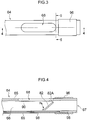
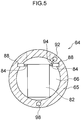
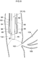
- Figure 3 to Figure 5 are schematic views showing an exemplary configuration of the vicinity of a distal end of the tube main body 64, in which Figure 3 is a plan view thereof, Figure 4 is a lateral cross-sectional view (cross-sectional view taken along line 4-4 in Figure 3 ) thereof, and Figure 5 is a cross-sectional view (cross-sectional view taken along line 5-5 in Figure 3 ) thereof.
- a passage 66 is provided to extend along an axis of the tube main body 64 inside the tube main body 64, and openings which are end parts of the passage 66 are formed at a distal end and a proximal end of the tube main body 64.
- the opening at the distal end is referred to as a distal end opening part 67.
- the passage 66 is a channel through which the insertion part 12 of the endoscope 10 (see Figure 1 ) is passed, and a cross-sectional shape thereof perpendicular to the axis direction is formed into a substantially circular shape.
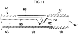
- a sidewall portion 65 on the distal end side of the tube main body 64 is provided with an opening part 68 composed of a through hole with an oval shape in which the axial direction of the tube main body 64 is its longitudinal direction (hereinafter referred to as sidewall opening part 68).
- This sidewall opening part 68 is a hole part having a size at which the insertion part 12 passed through the passage 66 can pass through it, and is formed such that an opening width of the opening part 68 (length thereof in a direction perpendicular to the axial direction of the tube main body 64) is slightly larger than the outer diameter of the insertion part 12 of the endoscope 10 (diameter) and a length thereof (length in the axial direction of the tube main body 64) is sufficiently larger than the opening width.
- the distal end of the insertion part 12 can be fed to the outside through the sidewall opening part 68 of the tube main body 64.
- the passage 66 of the tube main body 64 is provided with a guiding valve 82 swingably supported at a position in the vicinity of the distal end of the sidewall opening part 68, a direction perpendicular to the axial direction of the tube main body 64 being a supporting axis 82A.
- the guiding valve 82 is formed into a plate shape, and as shown in Figure 5 , shaft pins 84, 84 protrude on both side faces on the proximal end side thereof.
- shaft pins 84 are rotatably supported on shaft receiving members 88, 88 embedded in the sidewall portion 65 of the tube main body 64, while urged in a predetermined rotation direction by a helical torsion coil spring, for example, intervening between the shaft receiving members 88, 88 and the shaft pins 84, 84.
- the guiding valve 82 at a position where the end part of the guiding valve 82 on the supporting axis 82A side is positioned more proximally than the end part of the sidewall opening part 68 on its distal end side.
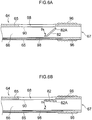
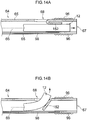
- the guiding valve 82 is swingably supported in the A-B direction in the figure and make a transition between an inclined state where it is inclined relative to the axial direction of the tube main body 64 (passage 66) and occludes the passage 66 that is positioned more distally than the position where the guiding valve 82 is provided, as shown in Figure 6A , and a parallel state (retracted state) where it is substantially parallel to the axial direction of the tube main body 64 (passage 66) and releases the passage 66 that is positioned more distally than the position where the guiding valve 82 is provided, as shown in Figure 6B .
- the guiding valve 82 is urged in A direction, and unless tractive force is applied to the guiding valve 82 by a manipulating wire 90 mentioned later, the guiding valve 82 is held in the inclined state as shown in Figure 6A . In addition, in the inclined state, the distal end portion of the guiding valve 82 comes into contact with the inner wall surface of the passage 66 as shown in Figure 5 to regulate further rotation in A direction.
- urging means urging the guiding valve 82 in the predetermined direction is not limited to the helical torsion coil spring.
- the guiding valve 82 is pulled in B direction by the manipulating wire 90.
- the manipulating wire 90 is wound on the shaft pin 84 to be attached in such a direction that a wound amount of the manipulating wire 90 is more in the inclined state of the guiding valve 82 than in the parallel state thereof.
- the manipulating wire 90 passes through the inside of a wire channel 92 extending in the sidewall portion 65 of the tube main body 64 along the axial direction (longitudinal direction), and the distal end portion of the manipulating wire 90 is fed from the wire channel 92 into the passage 66 in the vicinity position of the guiding valve 82 to be attached to the shaft pin 84 of the guiding valve 82.
- a wire tube 94 having a channel in communication with the wire channel 92 extends to be provided and the proximal end side of the manipulating wire 90 is extended from a proximal end opening of the wire tube 94.
- an operator can perform switching of the guiding valve 82 between the parallel state and the inclined state as mentioned above.
- the insertion part 12 of the endoscope 10 is inserted into the passage 66 of the tube main body 64 from the proximal end opening part 62A of the grasping part 62, when the manipulating wire 90 is pulled to allow the guiding valve 82 to be in the parallel state, the insertion part 12 can be inserted to the distal end of the passage 66 and the insertion part 12 can be fed from the distal end opening part 67.
- the manipulating wire 90 is not needed to be pulled after that but may be slacked off.
- the manipulating wire 90 is slacked off before passing the insertion part 12 through the position of the guiding valve 82 to allow the guiding valve 82 to be in the inclined state, the insertion part 12 is guided in the direction of the sidewall opening part 68 by the guiding valve 82, and thereby, the insertion part 12 can be easily fed from the sidewall opening part 68.
- the guiding valve 82 may have a size and a shape to the extent that in the inclined state, the insertion part 12 is not passed through spacing between the guiding valve 82 and the inner wall of the passage 66 (inner surface of the sidewall portion 65 of the tube main body 64) to the passage 66 that is positioned more distally than the guiding valve 82.
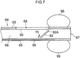
- an inflatable and deflatable balloon 96 is attached to a sidewall outer peripheral surface that is positioned more distally than the sidewall opening part 68 of the tube main body 64.
- This balloon 96 is in communication with a fluid channel 98 extending along the axial direction in the sidewall portion 65 of the tube main body 64, and the fluid channel 98 is in communication with a channel in a tube 74 shown in Figure 1 which extends to the proximal end side of the tube main body 64.
- An end of the tube 74 is provided with a connector 76 and, by the connector 76, the tube 74 is connected to a balloon controlling device 78.
- the balloon controlling device 78 is a device supplying a fluid such as air to the channel in the tube 74 connected by the connector 76 and also sucking the fluid from the channel in the tube 74.
- the balloon controlling device 78 supplies the fluid to the channel in the tube 74, and thereby allowing the fluid supplied to the channel to flow through the fluid channel 98 of the tube main body 64 and to be injected into the balloon 96. This causes the balloon 96 to inflate annularly around the tube main body 64 as shown in Figure 7 .
- the balloon controlling device 78 sucks the fluid from the channel in the tube 74, and thereby allowing the balloon 96 to discharge the fluid injected into the balloon 96 into the fluid channel 98 of the tube main body 64, so that the balloon controlling device 78 allows the fluid to flow through the fluid channel 98 and the channel in the tube 74 and to be sucked.
- the balloon 96 is configured to be deflatable.
- the insertion part 12 of the endoscope 10 is covered with the insertion assisting tool 60, the insertion part 12 is passed into the passage 66 of the tube main body 64 as shown in Figure 8 , and in this state, the insertion part 12 and the tube main body 64 are inserted through a patient's mouth and inserted into a duodenum 100 through the stomach, while the angle knobs 36, 36 of the endoscope 10 are operated to appropriately perform bending operation of the bending part 42.
- the guiding valve 82 has been allowed to be in the parallel state as shown in Figure 6B , the insertion part 12 has been put forward into the passage 66 that is positioned more distally than the guiding valve 82, and the distal end of the insertion part 12 has been fed from the distal end opening part 67. Moreover, the balloon 96 has been in a deflated state.
- the insertion assisting tool 60 is put further forward into a deep portion (distal end side) of the duodenum 100, and positioning is performed so as to allow the sidewall opening part 68 of the tube main body 64 to face the major duodenal papilla 102, as shown in Figure 9 .
- the balloon controlling device 78 injects the fluid into the balloon 96 to inflate the balloon 96 and to bring the balloon 96 into close contact with an inner wall of the duodenum 100, allowing to fix the position of the tube main body 64 in the duodenum 100 and to hold the sidewall opening part 68 of the tube main body 64 at a position opposite to the major duodenal papilla 102.
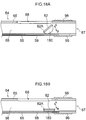
- the insertion part 12 is put further forward while undergone bent operation, the distal end of the insertion part 12 is fed from the sidewall opening part 68 of the tube main body 64 as shown in Figure 10 , and the distal end thereof is inserted into the biliary tract (common bile duct) 104 from the major duodenal papilla 102.
- the guiding valve 82 is in the inclined state as shown in Figure 6A , when putting the insertion part 12 further forward, the insertion part 12 is guided by the guiding valve 82 to be easily and smoothly fed from the sidewall opening part 68.
- the distal end side of the insertion part 12 is bent into a J-shape by the bending part 42 and inserted into the biliary tract 104, the distal end of the insertion part 12 is guided while the bending part 42 is received and supported on the outer surface of the balloon 96, and therefore, force to the insertion direction works effectively and the distal end of the insertion part 12 can be easily inserted into the biliary tract 104. Then, the distal end of the insertion part 12 can be put further forward gradually into a deep portion thereof.
- the insertion part 12 of the endoscope 10 can be easily and smoothly fed from the sidewall opening part 68 provided to the sidewall portion 65 of the tube main body 64. Moreover, the insertion part 12 can be easily inserted into the biliary tract 104 or the pancreatic duct 106, while received and supported on the inflated balloon 96.
- the guiding valve 82 is fixedly held in the inclined state by causing the proximal end side of the guiding valve 82 to come into contact with the inner wall surface of the tube main body 64, the distal end side of the guiding valve 82 (end part of the guiding valve 82 being on the distal end side of the tube main body 64) being the rotation fulcrum as in the embodiment, compared with a case where the distal end side of the guiding valve 82 is caused to face the sidewall opening part 68 and fixedly held in the inclined state, the proximal end side of the guiding valve 82 being the rotation fulcrum, there is no need for any special locking mechanism or the like for regulating rotation of the guiding valve 82 against the load from the insertion part 12 and fixedly holding it in the inclined state, enabling the configuration to be simple.
- an endoscope with a very fine insertion part that does not include any forceps channel may be used as the endoscope 10.
- the guiding valve 82 of the tube main body 64 is urged so as to be in the inclined state as shown in Figure 6A in a state where the manipulating wire 90 is slacked off, whereas it may be urged in the direction opposite to that in the embodiment (B direction) so as to be in the parallel state as shown in Figure 6B in a state where the manipulating wire 90 is slacked off.
- the manipulating wire 90 may be wound to be attached in such a direction that a wound amount the manipulating wire 90 is more in the parallel state of the guiding valve 82 than in the inclined state thereof.
- the guiding valve 82 is in the parallel state as shown in Figure 6B , and when pulling the manipulating wire 90 toward the proximal end side, the guiding valve 82 rotates to A direction so as to be in the inclined state of Figure 6A .
- the manipulating wire 90 pulling the guiding valve 82 of the tube main body 64 is attached to the shaft pin 84 of the guiding valve 82, whereas, not limited to this, it may be attached to the guiding valve 82.
- the manipulating wire 90 which is passed through the wire channel extending in the sidewall portion 65 of the tube main body 64 may be fed in the passage 66 from a position on B direction side relative to the guiding valve 82 in the inclined state, and, the distal end of the manipulating wire 90 may be fixedly attached to a distal end portion of the guiding valve 82.
- the guiding valve 82 may be biased by predetermined biasing means in B direction on the contrary to the embodiment in which the guiding valve 82 is rotated by the manipulating wire to A direction.
Landscapes
- Health & Medical Sciences (AREA)
- Life Sciences & Earth Sciences (AREA)
- Surgery (AREA)
- Biomedical Technology (AREA)
- Medical Informatics (AREA)
- Optics & Photonics (AREA)
- Pathology (AREA)
- Radiology & Medical Imaging (AREA)
- Biophysics (AREA)
- Engineering & Computer Science (AREA)
- Physics & Mathematics (AREA)
- Heart & Thoracic Surgery (AREA)
- Nuclear Medicine, Radiotherapy & Molecular Imaging (AREA)
- Molecular Biology (AREA)
- Animal Behavior & Ethology (AREA)
- General Health & Medical Sciences (AREA)
- Public Health (AREA)
- Veterinary Medicine (AREA)
- Endoscopes (AREA)
- Instruments For Viewing The Inside Of Hollow Bodies (AREA)
Priority Applications (1)
| Application Number | Priority Date | Filing Date | Title |
|---|---|---|---|
| EP18205759.6A EP3461391B1 (en) | 2011-03-31 | 2012-03-06 | Insertion assisting tool for endoscope |
Applications Claiming Priority (2)
| Application Number | Priority Date | Filing Date | Title |
|---|---|---|---|
| JP2011079218A JP5663373B2 (ja) | 2011-03-31 | 2011-03-31 | 内視鏡用挿入補助具 |
| PCT/JP2012/055618 WO2012132778A1 (ja) | 2011-03-31 | 2012-03-06 | 内視鏡用挿入補助具 |
Related Child Applications (1)
| Application Number | Title | Priority Date | Filing Date |
|---|---|---|---|
| EP18205759.6A Division EP3461391B1 (en) | 2011-03-31 | 2012-03-06 | Insertion assisting tool for endoscope |
Publications (3)
| Publication Number | Publication Date |
|---|---|
| EP2692273A1 EP2692273A1 (en) | 2014-02-05 |
| EP2692273A4 EP2692273A4 (en) | 2014-08-20 |
| EP2692273B1 true EP2692273B1 (en) | 2018-12-05 |
Family
ID=46930525
Family Applications (2)
| Application Number | Title | Priority Date | Filing Date |
|---|---|---|---|
| EP12763908.6A Not-in-force EP2692273B1 (en) | 2011-03-31 | 2012-03-06 | Endoscope insertion assitive device |
| EP18205759.6A Not-in-force EP3461391B1 (en) | 2011-03-31 | 2012-03-06 | Insertion assisting tool for endoscope |
Family Applications After (1)
| Application Number | Title | Priority Date | Filing Date |
|---|---|---|---|
| EP18205759.6A Not-in-force EP3461391B1 (en) | 2011-03-31 | 2012-03-06 | Insertion assisting tool for endoscope |
Country Status (4)
| Country | Link |
|---|---|
| US (2) | US9986897B2 (enExample) |
| EP (2) | EP2692273B1 (enExample) |
| JP (1) | JP5663373B2 (enExample) |
| WO (1) | WO2012132778A1 (enExample) |
Families Citing this family (19)
| Publication number | Priority date | Publication date | Assignee | Title |
|---|---|---|---|---|
| US11172809B2 (en) * | 2013-02-15 | 2021-11-16 | Intuitive Surgical Operations, Inc. | Vision probe with access port |
| JP5752740B2 (ja) * | 2013-05-15 | 2015-07-22 | 富士システムズ株式会社 | 内視鏡用スライディングチューブ |
| JP6210908B2 (ja) * | 2014-03-17 | 2017-10-11 | オリンパス株式会社 | チューブ体及び内視鏡システム |
| US11234581B2 (en) * | 2014-05-02 | 2022-02-01 | Endochoice, Inc. | Elevator for directing medical tool |
| JP6351843B2 (ja) * | 2014-06-25 | 2018-07-04 | マッカイ メモリアル ホスピタルMackay Memorial Hospital | 超薄型内視鏡補助システム |
| US9913570B2 (en) | 2015-08-07 | 2018-03-13 | Enlightenvue Llc | Endoscope with variable profile tip |
| CN111065329A (zh) | 2017-06-30 | 2020-04-24 | 茵莱特恩视觉有限责任公司 | 内窥镜系统及其使用方法 |
| CN107714142A (zh) * | 2017-11-11 | 2018-02-23 | 宋勇 | 一种便携式胆道镜 |
| US10687698B2 (en) | 2018-09-12 | 2020-06-23 | Enlightenvue Llc | Direct endoluminal- and/or endovascular-illumination systems and methods of use thereof |
| US11883048B2 (en) * | 2018-12-07 | 2024-01-30 | Acclarent, Inc. | Instrument with integral imaging and irrigation features |
| US11925333B2 (en) | 2019-02-01 | 2024-03-12 | Covidien Lp | System for fluoroscopic tracking of a catheter to update the relative position of a target and the catheter in a 3D model of a luminal network |
| EP4631416A2 (en) | 2019-04-23 | 2025-10-15 | Boston Scientific Scimed, Inc. | Modular scope device |
| JP7419407B2 (ja) * | 2019-06-28 | 2024-01-22 | 南▲微▼医学科技股▲フン▼有限公司 | オーバーチューブ装置および内視鏡アッセンブリ |
| US11786113B2 (en) * | 2020-01-07 | 2023-10-17 | Gyrus Acmi, Inc. | Endoscope with low-profile distal section |
| EP4117500A1 (en) * | 2020-03-10 | 2023-01-18 | Boston Scientific Scimed Inc. | Devices, systems, and methods for an instrument accessory |
| US20220280135A1 (en) * | 2021-03-04 | 2022-09-08 | Covidien Lp | Endoscope or catheter assemblies including two or more exit ports |
| WO2022187705A1 (en) * | 2021-03-04 | 2022-09-09 | Covidien Lp | Endoscope or catheter assemblies including two or more exit ports |
| CN114557733B (zh) * | 2022-02-28 | 2023-03-21 | 常州市久虹医疗器械有限公司 | 一种内窥镜用活检阀 |
| CN119791565B (zh) * | 2025-03-14 | 2025-06-13 | 湖南省华芯医疗器械有限公司 | 一种涡流组件、插入部及内窥镜 |
Citations (1)
| Publication number | Priority date | Publication date | Assignee | Title |
|---|---|---|---|---|
| US20050090709A1 (en) * | 2003-09-23 | 2005-04-28 | Olympus Corporation | Endoscope suitable to body cavity |
Family Cites Families (22)
| Publication number | Priority date | Publication date | Assignee | Title |
|---|---|---|---|---|
| US4224929A (en) * | 1977-11-08 | 1980-09-30 | Olympus Optical Co., Ltd. | Endoscope with expansible cuff member and operation section |
| JPS60185532A (ja) * | 1984-03-05 | 1985-09-21 | オリンパス光学工業株式会社 | 内視鏡用挿入補助具 |
| JPS6222623A (ja) * | 1985-07-24 | 1987-01-30 | オリンパス光学工業株式会社 | 内視鏡用插入補助具 |
| JPS62102731A (ja) * | 1985-10-30 | 1987-05-13 | オリンパス光学工業株式会社 | 内視鏡用案内管 |
| JPS62292135A (ja) * | 1986-06-12 | 1987-12-18 | オリンパス光学工業株式会社 | 内視鏡用挿入補助具 |
| DE3621509A1 (de) * | 1986-06-27 | 1988-03-03 | Wolf Gmbh Richard | Seitenblick-endoskop |
| US5152277A (en) * | 1987-07-23 | 1992-10-06 | Terumo Kabushiki Kaisha | Catheter tube |
| US4982724A (en) * | 1987-12-28 | 1991-01-08 | Olympus Opicals Co. | Endoscope apparatus |
| US5460168A (en) * | 1992-12-25 | 1995-10-24 | Olympus Optical Co., Ltd. | Endoscope cover assembly and cover-system endoscope |
| DE10358817B3 (de) * | 2003-12-16 | 2005-04-14 | Olympus Winter & Ibe Gmbh | Endoskop |
| JP4025755B2 (ja) * | 2004-07-02 | 2007-12-26 | オリンパス株式会社 | 内視鏡 |
| KR100865834B1 (ko) * | 2004-10-05 | 2008-10-28 | 올림푸스 가부시키가이샤 | 내시경 시스템 및 생체 시료 수용 용기 |
| JP4921774B2 (ja) * | 2005-11-08 | 2012-04-25 | オリンパス株式会社 | 内視鏡用照明具及び内視鏡装置 |
| WO2007063904A1 (ja) * | 2005-12-01 | 2007-06-07 | Olympus Medical Systems Corp. | ガイド用細長医療部材、及び細長医療装置 |
| JP4884046B2 (ja) * | 2006-03-22 | 2012-02-22 | 富士フイルム株式会社 | 超音波内視鏡 |
| US8002698B2 (en) * | 2007-04-04 | 2011-08-23 | Olympus Medical Systems Corp. | Therapeutic method that uses overtube |
| JP4642936B2 (ja) * | 2009-02-09 | 2011-03-02 | オリンパスメディカルシステムズ株式会社 | 医療用チューブ |
| JP5313068B2 (ja) * | 2009-03-09 | 2013-10-09 | 富士フイルム株式会社 | 側視内視鏡装置 |
| JP5487745B2 (ja) * | 2009-06-12 | 2014-05-07 | 横浜ゴム株式会社 | 扉開閉装置 |
| JP5491084B2 (ja) * | 2009-07-01 | 2014-05-14 | 幹人 黒田 | 内視鏡装置 |
| JP5631177B2 (ja) * | 2009-11-28 | 2014-11-26 | 欣也 藤田 | 内視鏡誘導用管状部材 |
| JP5437300B2 (ja) * | 2011-03-17 | 2014-03-12 | 富士フイルム株式会社 | 内視鏡用挿入補助具 |
-
2011
- 2011-03-31 JP JP2011079218A patent/JP5663373B2/ja active Active
-
2012
- 2012-03-06 WO PCT/JP2012/055618 patent/WO2012132778A1/ja not_active Ceased
- 2012-03-06 EP EP12763908.6A patent/EP2692273B1/en not_active Not-in-force
- 2012-03-06 EP EP18205759.6A patent/EP3461391B1/en not_active Not-in-force
-
2013
- 2013-09-27 US US14/039,902 patent/US9986897B2/en active Active
-
2018
- 2018-05-02 US US15/969,404 patent/US10441143B2/en active Active
Patent Citations (1)
| Publication number | Priority date | Publication date | Assignee | Title |
|---|---|---|---|---|
| US20050090709A1 (en) * | 2003-09-23 | 2005-04-28 | Olympus Corporation | Endoscope suitable to body cavity |
Also Published As
| Publication number | Publication date |
|---|---|
| US20180249897A1 (en) | 2018-09-06 |
| JP2012213435A (ja) | 2012-11-08 |
| JP5663373B2 (ja) | 2015-02-04 |
| US10441143B2 (en) | 2019-10-15 |
| EP3461391B1 (en) | 2020-04-22 |
| US20140024897A1 (en) | 2014-01-23 |
| US9986897B2 (en) | 2018-06-05 |
| EP3461391A1 (en) | 2019-04-03 |
| EP2692273A4 (en) | 2014-08-20 |
| EP2692273A1 (en) | 2014-02-05 |
| WO2012132778A1 (ja) | 2012-10-04 |
Similar Documents
| Publication | Publication Date | Title |
|---|---|---|
| EP2692273B1 (en) | Endoscope insertion assitive device | |
| JP4025755B2 (ja) | 内視鏡 | |
| JP5231258B2 (ja) | 改良型カテーテルを有する内視鏡装置 | |
| JP5437300B2 (ja) | 内視鏡用挿入補助具 | |
| JP4547184B2 (ja) | 内視鏡用アダプター及び内視鏡 | |
| JP5327986B2 (ja) | 内視鏡用挿入補助具 | |
| EP3664682B1 (en) | Adaptor for an endoscope | |
| US20240407632A1 (en) | Endoscopic tool stabilization and related methods of use | |
| JP5496140B2 (ja) | 内視鏡用挿入補助具 | |
| JP4414827B2 (ja) | 内視鏡 | |
| EP2534998B1 (en) | Insertion assisting tool for endoscope | |
| JP5498422B2 (ja) | 内視鏡用挿入補助具 | |
| JP2007268147A (ja) | 医療装置 | |
| JP5390150B2 (ja) | 補助具及び内視鏡システム | |
| US20250169880A1 (en) | Endoscopic treatment tool and endoscopic treatment system | |
| JP2010136990A (ja) | 内視鏡システム及び補助具 | |
| JP2005230087A (ja) | オーバチューブ |
Legal Events
| Date | Code | Title | Description |
|---|---|---|---|
| PUAI | Public reference made under article 153(3) epc to a published international application that has entered the european phase |
Free format text: ORIGINAL CODE: 0009012 |
|
| 17P | Request for examination filed |
Effective date: 20130927 |
|
| AK | Designated contracting states |
Kind code of ref document: A1 Designated state(s): AL AT BE BG CH CY CZ DE DK EE ES FI FR GB GR HR HU IE IS IT LI LT LU LV MC MK MT NL NO PL PT RO RS SE SI SK SM TR |
|
| DAX | Request for extension of the european patent (deleted) | ||
| A4 | Supplementary search report drawn up and despatched |
Effective date: 20140722 |
|
| RIC1 | Information provided on ipc code assigned before grant |
Ipc: A61B 1/00 20060101AFI20140716BHEP Ipc: G02B 23/24 20060101ALI20140716BHEP |
|
| 17Q | First examination report despatched |
Effective date: 20150521 |
|
| STAA | Information on the status of an ep patent application or granted ep patent |
Free format text: STATUS: EXAMINATION IS IN PROGRESS |
|
| GRAP | Despatch of communication of intention to grant a patent |
Free format text: ORIGINAL CODE: EPIDOSNIGR1 |
|
| STAA | Information on the status of an ep patent application or granted ep patent |
Free format text: STATUS: GRANT OF PATENT IS INTENDED |
|
| INTG | Intention to grant announced |
Effective date: 20180709 |
|
| GRAS | Grant fee paid |
Free format text: ORIGINAL CODE: EPIDOSNIGR3 |
|
| GRAA | (expected) grant |
Free format text: ORIGINAL CODE: 0009210 |
|
| GRAA | (expected) grant |
Free format text: ORIGINAL CODE: 0009210 |
|
| STAA | Information on the status of an ep patent application or granted ep patent |
Free format text: STATUS: THE PATENT HAS BEEN GRANTED |
|
| AK | Designated contracting states |
Kind code of ref document: B1 Designated state(s): AL AT BE BG CH CY CZ DE DK EE ES FI FR GB GR HR HU IE IS IT LI LT LU LV MC MK MT NL NO PL PT RO RS SE SI SK SM TR |
|
| REG | Reference to a national code |
Ref country code: GB Ref legal event code: FG4D |
|
| REG | Reference to a national code |
Ref country code: CH Ref legal event code: EP |
|
| REG | Reference to a national code |
Ref country code: AT Ref legal event code: REF Ref document number: 1072009 Country of ref document: AT Kind code of ref document: T Effective date: 20181215 |
|
| REG | Reference to a national code |
Ref country code: IE Ref legal event code: FG4D |
|
| REG | Reference to a national code |
Ref country code: DE Ref legal event code: R096 Ref document number: 602012054356 Country of ref document: DE |
|
| REG | Reference to a national code |
Ref country code: NL Ref legal event code: MP Effective date: 20181205 |
|
| REG | Reference to a national code |
Ref country code: AT Ref legal event code: MK05 Ref document number: 1072009 Country of ref document: AT Kind code of ref document: T Effective date: 20181205 |
|
| REG | Reference to a national code |
Ref country code: LT Ref legal event code: MG4D |
|
| PG25 | Lapsed in a contracting state [announced via postgrant information from national office to epo] |
Ref country code: LV Free format text: LAPSE BECAUSE OF FAILURE TO SUBMIT A TRANSLATION OF THE DESCRIPTION OR TO PAY THE FEE WITHIN THE PRESCRIBED TIME-LIMIT Effective date: 20181205 Ref country code: ES Free format text: LAPSE BECAUSE OF FAILURE TO SUBMIT A TRANSLATION OF THE DESCRIPTION OR TO PAY THE FEE WITHIN THE PRESCRIBED TIME-LIMIT Effective date: 20181205 Ref country code: LT Free format text: LAPSE BECAUSE OF FAILURE TO SUBMIT A TRANSLATION OF THE DESCRIPTION OR TO PAY THE FEE WITHIN THE PRESCRIBED TIME-LIMIT Effective date: 20181205 Ref country code: BG Free format text: LAPSE BECAUSE OF FAILURE TO SUBMIT A TRANSLATION OF THE DESCRIPTION OR TO PAY THE FEE WITHIN THE PRESCRIBED TIME-LIMIT Effective date: 20190305 Ref country code: HR Free format text: LAPSE BECAUSE OF FAILURE TO SUBMIT A TRANSLATION OF THE DESCRIPTION OR TO PAY THE FEE WITHIN THE PRESCRIBED TIME-LIMIT Effective date: 20181205 Ref country code: FI Free format text: LAPSE BECAUSE OF FAILURE TO SUBMIT A TRANSLATION OF THE DESCRIPTION OR TO PAY THE FEE WITHIN THE PRESCRIBED TIME-LIMIT Effective date: 20181205 Ref country code: NO Free format text: LAPSE BECAUSE OF FAILURE TO SUBMIT A TRANSLATION OF THE DESCRIPTION OR TO PAY THE FEE WITHIN THE PRESCRIBED TIME-LIMIT Effective date: 20190305 Ref country code: AT Free format text: LAPSE BECAUSE OF FAILURE TO SUBMIT A TRANSLATION OF THE DESCRIPTION OR TO PAY THE FEE WITHIN THE PRESCRIBED TIME-LIMIT Effective date: 20181205 |
|
| PG25 | Lapsed in a contracting state [announced via postgrant information from national office to epo] |
Ref country code: GR Free format text: LAPSE BECAUSE OF FAILURE TO SUBMIT A TRANSLATION OF THE DESCRIPTION OR TO PAY THE FEE WITHIN THE PRESCRIBED TIME-LIMIT Effective date: 20190306 Ref country code: RS Free format text: LAPSE BECAUSE OF FAILURE TO SUBMIT A TRANSLATION OF THE DESCRIPTION OR TO PAY THE FEE WITHIN THE PRESCRIBED TIME-LIMIT Effective date: 20181205 Ref country code: AL Free format text: LAPSE BECAUSE OF FAILURE TO SUBMIT A TRANSLATION OF THE DESCRIPTION OR TO PAY THE FEE WITHIN THE PRESCRIBED TIME-LIMIT Effective date: 20181205 Ref country code: SE Free format text: LAPSE BECAUSE OF FAILURE TO SUBMIT A TRANSLATION OF THE DESCRIPTION OR TO PAY THE FEE WITHIN THE PRESCRIBED TIME-LIMIT Effective date: 20181205 |
|
| PG25 | Lapsed in a contracting state [announced via postgrant information from national office to epo] |
Ref country code: NL Free format text: LAPSE BECAUSE OF FAILURE TO SUBMIT A TRANSLATION OF THE DESCRIPTION OR TO PAY THE FEE WITHIN THE PRESCRIBED TIME-LIMIT Effective date: 20181205 |
|
| PG25 | Lapsed in a contracting state [announced via postgrant information from national office to epo] |
Ref country code: PT Free format text: LAPSE BECAUSE OF FAILURE TO SUBMIT A TRANSLATION OF THE DESCRIPTION OR TO PAY THE FEE WITHIN THE PRESCRIBED TIME-LIMIT Effective date: 20190405 Ref country code: IT Free format text: LAPSE BECAUSE OF FAILURE TO SUBMIT A TRANSLATION OF THE DESCRIPTION OR TO PAY THE FEE WITHIN THE PRESCRIBED TIME-LIMIT Effective date: 20181205 Ref country code: CZ Free format text: LAPSE BECAUSE OF FAILURE TO SUBMIT A TRANSLATION OF THE DESCRIPTION OR TO PAY THE FEE WITHIN THE PRESCRIBED TIME-LIMIT Effective date: 20181205 Ref country code: PL Free format text: LAPSE BECAUSE OF FAILURE TO SUBMIT A TRANSLATION OF THE DESCRIPTION OR TO PAY THE FEE WITHIN THE PRESCRIBED TIME-LIMIT Effective date: 20181205 |
|
| PG25 | Lapsed in a contracting state [announced via postgrant information from national office to epo] |
Ref country code: RO Free format text: LAPSE BECAUSE OF FAILURE TO SUBMIT A TRANSLATION OF THE DESCRIPTION OR TO PAY THE FEE WITHIN THE PRESCRIBED TIME-LIMIT Effective date: 20181205 Ref country code: SK Free format text: LAPSE BECAUSE OF FAILURE TO SUBMIT A TRANSLATION OF THE DESCRIPTION OR TO PAY THE FEE WITHIN THE PRESCRIBED TIME-LIMIT Effective date: 20181205 Ref country code: IS Free format text: LAPSE BECAUSE OF FAILURE TO SUBMIT A TRANSLATION OF THE DESCRIPTION OR TO PAY THE FEE WITHIN THE PRESCRIBED TIME-LIMIT Effective date: 20190405 Ref country code: SM Free format text: LAPSE BECAUSE OF FAILURE TO SUBMIT A TRANSLATION OF THE DESCRIPTION OR TO PAY THE FEE WITHIN THE PRESCRIBED TIME-LIMIT Effective date: 20181205 Ref country code: EE Free format text: LAPSE BECAUSE OF FAILURE TO SUBMIT A TRANSLATION OF THE DESCRIPTION OR TO PAY THE FEE WITHIN THE PRESCRIBED TIME-LIMIT Effective date: 20181205 |
|
| REG | Reference to a national code |
Ref country code: DE Ref legal event code: R097 Ref document number: 602012054356 Country of ref document: DE |
|
| PLBE | No opposition filed within time limit |
Free format text: ORIGINAL CODE: 0009261 |
|
| STAA | Information on the status of an ep patent application or granted ep patent |
Free format text: STATUS: NO OPPOSITION FILED WITHIN TIME LIMIT |
|
| PG25 | Lapsed in a contracting state [announced via postgrant information from national office to epo] |
Ref country code: MC Free format text: LAPSE BECAUSE OF FAILURE TO SUBMIT A TRANSLATION OF THE DESCRIPTION OR TO PAY THE FEE WITHIN THE PRESCRIBED TIME-LIMIT Effective date: 20181205 Ref country code: SI Free format text: LAPSE BECAUSE OF FAILURE TO SUBMIT A TRANSLATION OF THE DESCRIPTION OR TO PAY THE FEE WITHIN THE PRESCRIBED TIME-LIMIT Effective date: 20181205 Ref country code: DK Free format text: LAPSE BECAUSE OF FAILURE TO SUBMIT A TRANSLATION OF THE DESCRIPTION OR TO PAY THE FEE WITHIN THE PRESCRIBED TIME-LIMIT Effective date: 20181205 |
|
| REG | Reference to a national code |
Ref country code: CH Ref legal event code: PL |
|
| 26N | No opposition filed |
Effective date: 20190906 |
|
| PG25 | Lapsed in a contracting state [announced via postgrant information from national office to epo] |
Ref country code: LU Free format text: LAPSE BECAUSE OF NON-PAYMENT OF DUE FEES Effective date: 20190306 |
|
| REG | Reference to a national code |
Ref country code: BE Ref legal event code: MM Effective date: 20190331 |
|
| REG | Reference to a national code |
Ref country code: DE Ref legal event code: R081 Ref document number: 602012054356 Country of ref document: DE Owner name: FUJIFILM CORPORATION, JP Free format text: FORMER OWNER: FUJIFILM CORP., TOKYO, JP |
|
| PG25 | Lapsed in a contracting state [announced via postgrant information from national office to epo] |
Ref country code: CH Free format text: LAPSE BECAUSE OF NON-PAYMENT OF DUE FEES Effective date: 20190331 Ref country code: IE Free format text: LAPSE BECAUSE OF NON-PAYMENT OF DUE FEES Effective date: 20190306 Ref country code: LI Free format text: LAPSE BECAUSE OF NON-PAYMENT OF DUE FEES Effective date: 20190331 |
|
| PG25 | Lapsed in a contracting state [announced via postgrant information from national office to epo] |
Ref country code: BE Free format text: LAPSE BECAUSE OF NON-PAYMENT OF DUE FEES Effective date: 20190331 |
|
| PG25 | Lapsed in a contracting state [announced via postgrant information from national office to epo] |
Ref country code: TR Free format text: LAPSE BECAUSE OF FAILURE TO SUBMIT A TRANSLATION OF THE DESCRIPTION OR TO PAY THE FEE WITHIN THE PRESCRIBED TIME-LIMIT Effective date: 20181205 |
|
| PG25 | Lapsed in a contracting state [announced via postgrant information from national office to epo] |
Ref country code: MT Free format text: LAPSE BECAUSE OF NON-PAYMENT OF DUE FEES Effective date: 20190306 |
|
| PGFP | Annual fee paid to national office [announced via postgrant information from national office to epo] |
Ref country code: FR Payment date: 20210210 Year of fee payment: 10 |
|
| PG25 | Lapsed in a contracting state [announced via postgrant information from national office to epo] |
Ref country code: CY Free format text: LAPSE BECAUSE OF FAILURE TO SUBMIT A TRANSLATION OF THE DESCRIPTION OR TO PAY THE FEE WITHIN THE PRESCRIBED TIME-LIMIT Effective date: 20181205 |
|
| PGFP | Annual fee paid to national office [announced via postgrant information from national office to epo] |
Ref country code: GB Payment date: 20210225 Year of fee payment: 10 |
|
| PG25 | Lapsed in a contracting state [announced via postgrant information from national office to epo] |
Ref country code: HU Free format text: LAPSE BECAUSE OF FAILURE TO SUBMIT A TRANSLATION OF THE DESCRIPTION OR TO PAY THE FEE WITHIN THE PRESCRIBED TIME-LIMIT; INVALID AB INITIO Effective date: 20120306 |
|
| PG25 | Lapsed in a contracting state [announced via postgrant information from national office to epo] |
Ref country code: MK Free format text: LAPSE BECAUSE OF FAILURE TO SUBMIT A TRANSLATION OF THE DESCRIPTION OR TO PAY THE FEE WITHIN THE PRESCRIBED TIME-LIMIT Effective date: 20181205 |
|
| GBPC | Gb: european patent ceased through non-payment of renewal fee |
Effective date: 20220306 |
|
| PG25 | Lapsed in a contracting state [announced via postgrant information from national office to epo] |
Ref country code: GB Free format text: LAPSE BECAUSE OF NON-PAYMENT OF DUE FEES Effective date: 20220306 Ref country code: FR Free format text: LAPSE BECAUSE OF NON-PAYMENT OF DUE FEES Effective date: 20220331 |
|
| P01 | Opt-out of the competence of the unified patent court (upc) registered |
Effective date: 20230515 |
|
| PGFP | Annual fee paid to national office [announced via postgrant information from national office to epo] |
Ref country code: DE Payment date: 20240130 Year of fee payment: 13 |
|
| REG | Reference to a national code |
Ref country code: DE Ref legal event code: R119 Ref document number: 602012054356 Country of ref document: DE |