WO2012132756A1 - 太陽電池用バックシート及びその製造方法、並びに太陽電池モジュール - Google Patents
太陽電池用バックシート及びその製造方法、並びに太陽電池モジュール Download PDFInfo
- Publication number
- WO2012132756A1 WO2012132756A1 PCT/JP2012/055282 JP2012055282W WO2012132756A1 WO 2012132756 A1 WO2012132756 A1 WO 2012132756A1 JP 2012055282 W JP2012055282 W JP 2012055282W WO 2012132756 A1 WO2012132756 A1 WO 2012132756A1
- Authority
- WO
- WIPO (PCT)
- Prior art keywords
- solar cell
- polyester film
- polyester
- layer
- polymer
- Prior art date
- Legal status (The legal status is an assumption and is not a legal conclusion. Google has not performed a legal analysis and makes no representation as to the accuracy of the status listed.)
- Ceased
Links
Classifications
-
- C—CHEMISTRY; METALLURGY
- C08—ORGANIC MACROMOLECULAR COMPOUNDS; THEIR PREPARATION OR CHEMICAL WORKING-UP; COMPOSITIONS BASED THEREON
- C08J—WORKING-UP; GENERAL PROCESSES OF COMPOUNDING; AFTER-TREATMENT NOT COVERED BY SUBCLASSES C08B, C08C, C08F, C08G or C08H
- C08J7/00—Chemical treatment or coating of shaped articles made of macromolecular substances
- C08J7/04—Coating
- C08J7/043—Improving the adhesiveness of the coatings per se, e.g. forming primers
-
- H—ELECTRICITY
- H10—SEMICONDUCTOR DEVICES; ELECTRIC SOLID-STATE DEVICES NOT OTHERWISE PROVIDED FOR
- H10F—INORGANIC SEMICONDUCTOR DEVICES SENSITIVE TO INFRARED RADIATION, LIGHT, ELECTROMAGNETIC RADIATION OF SHORTER WAVELENGTH OR CORPUSCULAR RADIATION
- H10F19/00—Integrated devices, or assemblies of multiple devices, comprising at least one photovoltaic cell covered by group H10F10/00, e.g. photovoltaic modules
- H10F19/80—Encapsulations or containers for integrated devices, or assemblies of multiple devices, having photovoltaic cells
- H10F19/85—Protective back sheets
-
- B—PERFORMING OPERATIONS; TRANSPORTING
- B32—LAYERED PRODUCTS
- B32B—LAYERED PRODUCTS, i.e. PRODUCTS BUILT-UP OF STRATA OF FLAT OR NON-FLAT, e.g. CELLULAR OR HONEYCOMB, FORM
- B32B27/00—Layered products comprising a layer of synthetic resin
- B32B27/36—Layered products comprising a layer of synthetic resin comprising polyesters
-
- C—CHEMISTRY; METALLURGY
- C08—ORGANIC MACROMOLECULAR COMPOUNDS; THEIR PREPARATION OR CHEMICAL WORKING-UP; COMPOSITIONS BASED THEREON
- C08J—WORKING-UP; GENERAL PROCESSES OF COMPOUNDING; AFTER-TREATMENT NOT COVERED BY SUBCLASSES C08B, C08C, C08F, C08G or C08H
- C08J7/00—Chemical treatment or coating of shaped articles made of macromolecular substances
- C08J7/04—Coating
- C08J7/0427—Coating with only one layer of a composition containing a polymer binder
-
- C—CHEMISTRY; METALLURGY
- C08—ORGANIC MACROMOLECULAR COMPOUNDS; THEIR PREPARATION OR CHEMICAL WORKING-UP; COMPOSITIONS BASED THEREON
- C08J—WORKING-UP; GENERAL PROCESSES OF COMPOUNDING; AFTER-TREATMENT NOT COVERED BY SUBCLASSES C08B, C08C, C08F, C08G or C08H
- C08J7/00—Chemical treatment or coating of shaped articles made of macromolecular substances
- C08J7/04—Coating
- C08J7/046—Forming abrasion-resistant coatings; Forming surface-hardening coatings
-
- H—ELECTRICITY
- H10—SEMICONDUCTOR DEVICES; ELECTRIC SOLID-STATE DEVICES NOT OTHERWISE PROVIDED FOR
- H10F—INORGANIC SEMICONDUCTOR DEVICES SENSITIVE TO INFRARED RADIATION, LIGHT, ELECTROMAGNETIC RADIATION OF SHORTER WAVELENGTH OR CORPUSCULAR RADIATION
- H10F71/00—Manufacture or treatment of devices covered by this subclass
-
- B—PERFORMING OPERATIONS; TRANSPORTING
- B32—LAYERED PRODUCTS
- B32B—LAYERED PRODUCTS, i.e. PRODUCTS BUILT-UP OF STRATA OF FLAT OR NON-FLAT, e.g. CELLULAR OR HONEYCOMB, FORM
- B32B2457/00—Electrical equipment
- B32B2457/12—Photovoltaic modules
-
- C—CHEMISTRY; METALLURGY
- C08—ORGANIC MACROMOLECULAR COMPOUNDS; THEIR PREPARATION OR CHEMICAL WORKING-UP; COMPOSITIONS BASED THEREON
- C08J—WORKING-UP; GENERAL PROCESSES OF COMPOUNDING; AFTER-TREATMENT NOT COVERED BY SUBCLASSES C08B, C08C, C08F, C08G or C08H
- C08J2367/00—Characterised by the use of polyesters obtained by reactions forming a carboxylic ester link in the main chain; Derivatives of such polymers
- C08J2367/02—Polyesters derived from dicarboxylic acids and dihydroxy compounds
-
- C—CHEMISTRY; METALLURGY
- C08—ORGANIC MACROMOLECULAR COMPOUNDS; THEIR PREPARATION OR CHEMICAL WORKING-UP; COMPOSITIONS BASED THEREON
- C08J—WORKING-UP; GENERAL PROCESSES OF COMPOUNDING; AFTER-TREATMENT NOT COVERED BY SUBCLASSES C08B, C08C, C08F, C08G or C08H
- C08J2427/00—Characterised by the use of homopolymers or copolymers of compounds having one or more unsaturated aliphatic radicals, each having only one carbon-to-carbon double bond, and at least one being terminated by a halogen; Derivatives of such polymers
- C08J2427/02—Characterised by the use of homopolymers or copolymers of compounds having one or more unsaturated aliphatic radicals, each having only one carbon-to-carbon double bond, and at least one being terminated by a halogen; Derivatives of such polymers not modified by chemical after-treatment
- C08J2427/12—Characterised by the use of homopolymers or copolymers of compounds having one or more unsaturated aliphatic radicals, each having only one carbon-to-carbon double bond, and at least one being terminated by a halogen; Derivatives of such polymers not modified by chemical after-treatment containing fluorine atoms
-
- Y—GENERAL TAGGING OF NEW TECHNOLOGICAL DEVELOPMENTS; GENERAL TAGGING OF CROSS-SECTIONAL TECHNOLOGIES SPANNING OVER SEVERAL SECTIONS OF THE IPC; TECHNICAL SUBJECTS COVERED BY FORMER USPC CROSS-REFERENCE ART COLLECTIONS [XRACs] AND DIGESTS
- Y02—TECHNOLOGIES OR APPLICATIONS FOR MITIGATION OR ADAPTATION AGAINST CLIMATE CHANGE
- Y02E—REDUCTION OF GREENHOUSE GAS [GHG] EMISSIONS, RELATED TO ENERGY GENERATION, TRANSMISSION OR DISTRIBUTION
- Y02E10/00—Energy generation through renewable energy sources
- Y02E10/50—Photovoltaic [PV] energy
-
- Y—GENERAL TAGGING OF NEW TECHNOLOGICAL DEVELOPMENTS; GENERAL TAGGING OF CROSS-SECTIONAL TECHNOLOGIES SPANNING OVER SEVERAL SECTIONS OF THE IPC; TECHNICAL SUBJECTS COVERED BY FORMER USPC CROSS-REFERENCE ART COLLECTIONS [XRACs] AND DIGESTS
- Y10—TECHNICAL SUBJECTS COVERED BY FORMER USPC
- Y10T—TECHNICAL SUBJECTS COVERED BY FORMER US CLASSIFICATION
- Y10T428/00—Stock material or miscellaneous articles
- Y10T428/31504—Composite [nonstructural laminate]
- Y10T428/3154—Of fluorinated addition polymer from unsaturated monomers
- Y10T428/31544—Addition polymer is perhalogenated
Definitions
- the present invention relates to a solar cell backsheet, a manufacturing method thereof, and a solar cell module that are provided on the opposite side of the solar cell element from the sunlight incident side.
- Solar cells are a power generation system that emits no carbon dioxide during power generation and has a low environmental load, and has been rapidly spreading in recent years.
- solar cells are usually sandwiched between a glass on which sunlight is incident and a so-called back sheet disposed on the side opposite to the side on which sunlight is incident (back surface side).
- a glass on which sunlight is incident and a so-called back sheet disposed on the side opposite to the side on which sunlight is incident (back surface side).
- the glass and the solar battery cell, and the solar battery cell and the back sheet are sealed with EVA (ethylene-vinyl acetate) resin or the like, respectively.
- EVA ethylene-vinyl acetate
- the solar cell power generation module has high weather resistance against the natural environment so that it can maintain battery performance such as power generation efficiency over a long period of several decades even under severe usage environment exposed to wind and rain and direct sunlight. It is necessary to be.
- weather resistance performance is required for various materials such as a back sheet constituting the solar cell power generation module and a sealing material for sealing the element.
- the back sheet has a function of preventing moisture from entering from the back surface of the solar cell module, and conventionally glass or fluororesin has been used, but in recent years, a polyester film seems to be used from the viewpoint of cost. It is becoming. And a back sheet is not a mere polymer sheet, and various functions may be provided.
- PET film As a polyester film applied as a back sheet, a polyethylene terephthalate (hereinafter also referred to as PET) film is particularly used, and various techniques have been proposed to improve weather resistance.
- Japanese Patent Application Laid-Open No. 2010-248492 discloses a PET film in which three or more kinds of components are coexisted in polyester.
- a specific endothermic peak temperature Tmeta (° C.) determined by terminal carboxyl group concentration and differential scanning calorimetry (DSC) is set as a specific range in order to improve hydrolysis resistance.
- a general PET film is a solar cell protective sheet, and in particular, when used as a back sheet for a solar cell, which is the outermost layer in particular, the PET film itself is easily peeled off when used for a long time.
- deterioration tends to occur, and in the case of a PET film single-layer backsheet, if it is placed for a long period of time in an environment exposed to wind and rain such as outdoors, the backsheet and the sealing material such as EVA peel off. It is easy to produce.
- a laminate-type back sheet in which a weather-resistant film is mainly bonded to the outermost layer side of a base film such as PET has been used for such a problem of weather resistance.
- a fluorine-based polymer film such as a polyvinyl fluoride film.
- a solar cell backsheet using a fluorine polymer film for example, a composite film of a fluorine polymer film and a metal foil, a fluorine polymer film, a silicon oxide thin film layer, and a laminate of a transparent resin (for example, JP-A-4-239634) and the like.
- a solar cell bag in which a cured coating film of a fluoropolymer paint containing a curable functional group is directly formed on a polyester film film.
- a sheet or a sheet coated with a fluoropolymer solution to which a conventionally known crosslinking agent or curing agent is added is disclosed.
- a cross-linking agent in the example of Japanese Patent Application Laid-Open No. 2010-053317, after performing corona surface treatment on the base material PET, A sheet coated with a fluoropolymer is disclosed.
- the surface treatment technology used in combination with such a fluoropolymer includes corona treatment, flame treatment and glow discharge treatment described in JP2010-053317A, as well as JP2002-282777A. Describes a method of irradiating with a special electromagnetic wave and a plasma treatment, and the examples of the document disclose a method of irradiating with a special electromagnetic wave and a mode of performing a plasma treatment, particularly under a low pressure condition close to vacuum. .
- the present invention has been made in view of the above circumstances, and provides a solar cell backsheet excellent in adhesion durability under wet heat aging environment, a method for producing the same, and a solar cell module having stable power generation efficiency. It is an object to achieve this purpose.
- a solar cell backsheet disposed in contact with the sealing material of the battery-side substrate in which the solar cell element is sealed with the sealing material, the polyester film base material and the polyester film base material
- the polyester film substrate has a terminal carboxyl group concentration of 15 eq / ton or less and 1 eq / ton or more, and a minute endothermic peak temperature Tmeta determined by differential scanning calorimetry. (° C.) is a polyester film substrate having an average elongation retention rate of 10% or more after being left for 72 hours under the conditions of a temperature of 125 ° C.
- At least one layer contains at least a fluorine-based polymer and is at least selected from a carbodiimide compound and an oxazoline compound.
- Has a crosslinked structure derived from one crosslinking agent, and a back sheet for a solar cell is formed is a polymer layer by coating.
- the polyester film substrate has a dicarboxylic acid component, a diol component, and a component (p) in which the total (a + b) of the number of carboxyl groups (a) and the number of hydroxyl groups (b) is 3 or more.
- the solar cell backsheet according to ⁇ 1> which contains polyester and the content of the constituent component (p) is 0.005 mol% to 2.5 mol% with respect to all the constituent components contained in the polyester. .
- the terminal blocker which is a carbodiimide compound, is contained in the range of 0.1% by mass to 5% by mass with respect to the total mass of the polyester contained in the polyester film substrate.
- the solar cell backsheet as described in any one of these.
- ⁇ 6> The solar cell backsheet according to any one of ⁇ 1> to ⁇ 5>, wherein the polyester film substrate is subjected to a surface treatment.
- the surface treatment is at least one surface treatment selected from a flame treatment using a flame introduced with a silane compound and an atmospheric pressure plasma treatment.
- the polymer layer having a crosslinked structure derived from at least one crosslinking agent selected from a carbodiimide-based compound and an oxazoline-based compound containing at least the fluorine-based polymer was subjected to a surface treatment on the polyester film substrate.
- ⁇ 6> or ⁇ 7> The solar cell backsheet according to ⁇ 7>, which is in direct contact with the surface.
- the polymer layer containing at least a fluorine-based polymer and having a crosslinked structure derived from at least one crosslinking agent selected from a carbodiimide compound and an oxazoline compound is an outermost layer of ⁇ 1> to ⁇ 8>
- the solar cell backsheet as described in any one.
- the terminal carboxyl group concentration is 1 eq / ton or more and 15 eq / ton or less
- the minute endothermic peak temperature Tmeta (° C.) obtained by differential scanning calorimetry is 220 ° C. or less
- the temperature is 125 ° C.
- the relative humidity is 100% RH.
- the manufacturing method of the solar cell backsheet including the process of apply
- ⁇ 12> including a step of applying at least one surface treatment selected from a flame treatment using a flame introduced with a silane compound and an atmospheric pressure plasma treatment on the surface of the polyester film substrate to which the coating solution is applied
- the manufacturing method of the solar cell backsheet ⁇ 13> The method for producing a back sheet for a solar cell according to ⁇ 11> or ⁇ 12>, wherein the coating liquid further contains a solvent, and 50% by mass or more of the solvent is water.
- ⁇ 14> Manufactured by the method for producing the solar cell backsheet according to any one of ⁇ 1> to ⁇ 10> or the solar cell backsheet according to any one of ⁇ 11> to ⁇ 13> Solar cell module provided with a back sheet for a solar cell.
- a transparent front substrate on which sunlight is incident a cell structure portion provided on the front substrate and having a solar cell element and a sealing material for sealing the solar cell device, and the cell structure portion
- a solar cell module comprising: a solar cell backsheet manufactured by the method for manufacturing a solar cell backsheet according to any one of> to ⁇ 13>.
- the present invention it is possible to provide a solar cell backsheet excellent in adhesion durability under wet heat aging environment, a method for producing the same, and a solar cell module having stable power generation efficiency.
- the solar cell backsheet of the present invention is a solar cell backsheet that is disposed in contact with the sealing material of a battery-side substrate in which solar cell elements are sealed with a sealing material, and is a polyester film substrate And at least one polymer layer provided on the polyester film substrate, the polyester film substrate has a terminal carboxyl group concentration of 1 eq / ton or more and 15 eq / ton or less, and differential scanning calorimetry A polyester film base having a minute endothermic peak temperature Tmeta (° C.) determined by a temperature of 220 ° C. or less, an average elongation retention rate of 10% or more after standing for 72 hours under conditions of a temperature of 125 ° C.
- Tmeta minute endothermic peak temperature
- a solar cell backsheet which is a polymer layer having a crosslinked structure derived from at least one crosslinking agent selected from a diimide compound and an oxazoline compound and formed by coating.
- the back sheet of the present invention has at least the terminal carboxyl group concentration, the minute endothermic peak temperature Tmeta (° C.) determined by differential scanning calorimetry, the temperature of 125 ° C., and the relative humidity of 100% RH as its constituent elements.
- Cross-linked structure derived from at least one cross-linking agent selected from a carbodiimide-based compound and an oxazoline-based compound that contains at least a fluorine-based polymer and a polyester film substrate having a specific range of average elongation retention after standing for 72 hours Therefore, the back sheet of the present invention has excellent adhesion durability with an adjacent member in a wet heat aging environment.
- the backsheet of the present invention can exhibit excellent durability over a long period of time under environmental conditions where it is exposed to heat and moisture for a long time. Furthermore, the solar cell module provided with such a back sheet of the present invention can obtain good power generation performance and can stably maintain power generation efficiency over a long period of time.
- the polyester film substrate in the present invention has a terminal carboxyl group concentration of 1 eq / ton or more and 15 eq / ton or less, and a minute endothermic peak temperature Tmeta (° C.) determined by differential scanning calorimetry (DSC) is 220 ° C. or less. It is a substrate made of a polyester film having an average elongation retention rate of 10% or more after being left for 72 hours under conditions of a temperature of 125 ° C. and a relative humidity of 100% RH.
- Tmeta minute endothermic peak temperature
- AV Terminal carboxyl group concentration
- the terminal carboxyl group concentration (hereinafter referred to as “AV” as appropriate) of the polyester contained in the polyester film is 1 eq / ton or more and 15 eq / ton or less, more preferably 2 eq / ton or more and 13 eq / ton or less, and still more preferably. It is 3 eq / ton or more and 9 eq / ton or less.
- “equivalent / ton (eq / t)” represents a molar equivalent per ton.
- the terminal carboxyl group functions to form a hydrogen bond with a hydroxyl group present on the surface of the member or layer adjacent to the polyester film to improve adhesion. Moreover, in this invention, it reacts with the carboxyl group (especially the carboxyl group which exists in the film surface) which exists in the polyester film which is a base material, and this invention is used using the specific crosslinking agent which forms a strong primary bond.
- this invention is used using the specific crosslinking agent which forms a strong primary bond.
- H + in the terminal carboxyl group acts as an acid catalyst and has an action of hydrolyzing the polyester molecule.
- Specific adjustment methods for AV include adjustment of the “plane orientation coefficient” of the polyester film, adjustment of the type and content of the “constituent component” constituting the polyester, “buffering agent”, “end-capping agent”, etc. Addition of additives, adjustment of “phosphorus atomic weight” present in the polyester, and the like can be mentioned.
- AV is within the scope of the present invention, depending on the amount of additives such as “buffering agent” and “end-capping agent” and / or “phosphorus atomic weight”. It is necessary to increase the content of these in the polyester.
- the polyester film in the present invention needs to be 1 eq / ton or more and 15 eq / ton or less.
- the terminal carboxyl group concentration (AV) is preferably in the range of 15 eq / ton or less in order to improve the hydrolysis resistance. It is preferably 13 eq / ton or less, more preferably 10 eq / ton or less, and most preferably 8 eq / ton or less.
- the lower limit is not particularly limited, but 0 eq / ton is the theoretical lower limit.
- AV of a pellet it can adjust with superposition
- the polyester film in the present invention has a minute endothermic peak temperature Tmeta (° C.) determined by differential scanning calorimetry (hereinafter also referred to as “DSC”) of 220 ° C. or less, more preferably 150 ° C. or more and 215 ° C. or less. More preferably, it is 160 degreeC or more and 210 degrees C or less.
- DSC differential scanning calorimetry
- the minute endothermic peak temperature Tmeta (° C.) is a range according to the present invention by controlling the “plane orientation coefficient” in the polyester film and the “temperature of heat setting performed after stretching” when forming the polyester film. can do.
- the heat setting temperature performed after stretching is preferably 150 ° C. or higher and 220 ° C. or lower, more preferably 160 ° C. or higher and 210 ° C. or lower, and further preferably 170 ° C. or higher and 200 ° C. or lower.
- the backsheet of the present invention is characterized by having high adhesion even after wet heat aging. For that purpose, it is preferable that the fall of adhesive force is suppressed by suppressing the hydrolysis in the polyester film surface. From such a viewpoint, as an index of hydrolysis on the surface of the polyester base material, “average elongation retention after standing for 72 hours under conditions of a temperature of 125 ° C. and a relative humidity of 100% RH” is employed. The average elongation retention is required to be 10% or more.
- the “average elongation retention rate” in the present invention is a measurement of the elongation retention rate in the longitudinal direction (MD) and the orthogonal direction (TD) of the polyester film, and is represented by the average value.
- Examples of methods for adjusting the elongation retention include adjustment of the “plane orientation coefficient” of the polyester film, adjustment of the “intrinsic viscosity” of the polyester, adjustment of the type and content of the “component” constituting the polyester polymer, “ Examples include addition of additives such as “buffering agent” and “end-capping agent”, and adjustment of “phosphorus atomic weight” present in the polyester.
- the polyester film in the present invention needs to have an average elongation retention of 10% or more, more preferably 20% or more and 95% or less, and further preferably 30% or more and 90% or less. is there. By setting the average elongation retention to 10% or more, it is possible to effectively suppress peeling (adhesion failure) of the back sheet due to hydrolysis of the polyester.
- One of the preferred embodiments of the polyester film in the present invention is that the thermal shrinkage rate at 150 ° C. for 30 minutes in the longitudinal direction (MD) and the orthogonal direction (TD) of the polyester film is 1.0% or less, respectively.
- the heat shrinkage variation ratio is 1% or more and 20% or less, respectively.
- the present inventors have obtained the knowledge that the poor adhesion due to the wet heat aging of the back sheet may be due to the occurrence of thermal shrinkage due to residual strain in the polyester film. That is, when heat shrinkage due to residual strain occurs in a polyester film that has been subjected to wet heat, shrinkage stress is generated between the sealing material such as EVA and the polyester film due to the heat shrinkage, which causes poor adhesion of the backsheet. It is to cause. In the polyester films described in JP 2010-248492 A and WO 2010/110119 pamphlet, the thermal shrinkage is reduced, but the adhesion failure can be sufficiently solved only by reducing the thermal shrinkage. Absent. On the other hand, in the polyester film according to a preferred embodiment of the present invention, the effect of suppressing poor adhesion can be improved by giving a distribution to the heat shrinkage.
- the preferable thermal shrinkage variation ratio of the polyester film of a preferred embodiment in the present invention is 1% or more and 20% or less, more preferably 2% or more and 15% or less, and further preferably 3% or more and 12% or less.
- Bts represents the heat shrinkage variation ratio
- Bmax represents the maximum value of heat shrinkage
- Bmin represents the minimum value of heat shrinkage
- Bav represents the average value of heat shrinkage.
- thermal shrinkage variation ratio exceeds 20%, the dimensional change between the large and small areas of thermal shrinkage becomes too large, and a crater-shaped shrinkage tends to occur, and stress concentration occurs along the edge of this crater. , Peeling (adhesion failure) is likely to occur.
- the thermal shrinkage variation ratio is less than 1%, it is difficult to achieve the effect of suppressing shrinkage as described above.
- heat shrinkage rate and the heat shrinkage variation ratio are particularly useful for revealing the effect of improving the adhesion after aging with wet heat.
- heat shrinkage occurs over time under high humidity, and in the case of high humidity, water penetrates the polyester film and the interface between adjacent members or adjacent layers that can form hydrogen bonds with the polyester film.
- the shrinkage stress due to residual strain can be reduced by controlling the heat shrinkage rate and the heat shrinkage variation ratio within the above range. This makes it easy to ensure adhesion.
- the thermal shrinkage rate of the polyester film in the present invention is measured at 150 ° C. for 30 minutes.
- the preferable range is preferably 1% or less in both the longitudinal direction (MD) and the orthogonal direction (TD), more preferably from ⁇ 0.5% to 0.8%, and still more preferably ⁇ 0.3. % Or more and 0.6% or less. (Here, “-” means “extension”).
- the effect of setting the heat shrinkage variation ratio in the specific range can be effectively expressed.
- the heat shrinkage rate exceeds 1%, the dimensional change of the polyester film cannot be completely suppressed, and the effect of setting the heat shrinkage variation ratio in a specific range tends to be not obtained.
- the elongation of the polyester film becomes too large, the effect of suppressing the dimensional change of the polyester film by controlling the heat shrinkage variation ratio tends to be not obtained.
- the heat shrinkage rate can be adjusted by performing a heat treatment after stretching when forming a polyester film.
- a preferable temperature for the heat treatment is 150 ° C. or higher and 220 ° C. or lower, more preferably 160 ° C. or higher and 210 ° C. or lower, more preferably 170 ° C. or higher and 200 ° C. or lower, and 10 seconds or longer and 120 seconds or shorter, more preferably 15 seconds or longer and 90 seconds or shorter. More preferably, it is 20 seconds or more and 60 seconds or less.
- the preferable relaxation amount is 0.5% or more and 10% or less, more preferably 1.5% or more and 9% or less. More preferably, it is 3% or more and 8% or less.
- the heat shrinkage variation ratio can be adjusted by forming a temperature distribution when solidifying on a cooling roll and producing an unstretched film (raw fabric) after melt extrusion when forming a polyester film. it can. That is, spherulites are formed when the melt cools, and this spherulite distribution is formed by changing the cooling rate. This causes an orientation distribution during longitudinal and lateral stretching, which appears as a distribution of shrinkage.
- Such distribution of the cooling rate of the melt can be achieved by giving a temperature distribution to the cooling roll. Such temperature distribution is achieved by disturbing the baffle plate with the flow of the heat medium flowing for temperature control in the cooling roll.
- a preferable temperature distribution is 0.2 ° C. or more and 10 ° C. or less, more preferably 0.4 ° C. or more and 5 ° C. or less, and further preferably 0.6 ° C. or more and 3 ° C. or less. These temperature distributions may be in either the longitudinal direction or the width direction.
- a “terminal sealing agent” is included in the polyester, and as a structural component of the polyester, “trifunctional or higher functional component (C)” By containing, the adhesion after wet heat aging can be improved more effectively.
- the end-capping agent can make the ends bulky by reacting with the polyester, which becomes a trap and decreases the mobility between the polyester molecules.
- the trifunctional or higher functional component (C) has a molecular branching via a trifunctional group, and thus reduces the mobility of the polyester molecule.
- the polyester film in the present invention preferably has a plane orientation coefficient of 0.165 or more, more preferably 0.168 or more and 0.18 or less, still more preferably 0.170 or more and 0.175 or less.
- the plane orientation coefficient By setting the plane orientation coefficient to 0.165 or more, the molecules can be oriented, the formation of the “half-crystal” can be promoted, and the hydrolysis resistance can be further improved.
- the plane orientation coefficient fPO referred to in the present invention is obtained from the following formula (A) using an Abbe refractometer.
- f PO (nMD + nTD) / 2 ⁇ nZD (A)
- nMD represents the refractive index in the longitudinal direction (MD) of the film
- nTD represents the refractive index in the perpendicular direction (TD) of the film
- nZD represents the refractive index in the film thickness direction.
- the refractive index of each said direction of a film can be measured based on A method etc. of JISK7142.
- the plane orientation coefficient of the polyester film can be adjusted by increasing the draw ratio during film formation.
- the draw ratio may be adjusted to 2.5 to 6.0 times in both the longitudinal direction (MD) of the film and the orthogonal direction (TD) of the film.
- MD longitudinal direction
- TD orthogonal direction
- the plane orientation coefficient can be improved by “preheating” and “multistage stretching” (described later) during longitudinal stretching.
- the plane orientation coefficient 0.165 or more, hydrolysis resistance can be suppressed and adhesion failure due to a decrease in molecular weight on the surface of the polyester film can be suppressed.
- the upper limit of the plane orientation coefficient of the film is that delamination (layer peeling) occurs because the film-forming stability deteriorates when the stretching ratio is increased to increase the plane orientation coefficient. ) Can be suppressed and the adhesion can be increased, so that it is preferably 0.180 or less, more preferably 0.175 or less.
- the distribution of the plane orientation coefficient is preferably 1% or more and 20% or less, more preferably 2% or more and 15% or less, and further preferably 3% or more and 12% or less.
- the adhesion can be further improved. That is, since the polyester film shrinks after aging with wet heat, shrinkage stress is generated between the film and a sealing material such as EVA, thereby causing poor adhesion. This heat shrinkage stress is proportional to the elastic modulus of the film, which is proportional to the plane orientation coefficient. Therefore, if there is a distribution in the polyester film plane orientation coefficient, a distribution is also generated in the elastic modulus, thereby forming a portion having a high elastic modulus (hard) and a portion having a low elastic modulus (soft).
- the portion having a low elastic modulus has a function of absorbing the generated heat shrinkage stress, and this acts as a buffer portion and exhibits the effect of suppressing the decrease in adhesion.
- the distribution of the plane orientation coefficient is less than 1%, the heat shrinkage stress cannot be relaxed and the adhesion tends to decrease.
- the distribution of the plane orientation coefficient exceeds 20%, the shrinkage stress is excessively concentrated on the small plane orientation, and the adhesion failure tends to occur.
- the distribution of the plane orientation coefficient in the polyester film can be formed by adjusting the preheating temperature distribution in the longitudinal stretching when forming the polyester film. That is, the orientation distribution in longitudinal stretching and the accompanying crystal distribution are formed by the preheating temperature distribution, thereby forming the orientation distribution in transverse stretching.
- the temperature distribution here refers to a temperature distribution in the width direction. That is, a crystal and orientation distribution occurs in the width direction after longitudinal stretching due to the temperature distribution formed in the width direction. When the film is stretched in the lateral direction thereafter, uneven distribution is formed over the entire surface of the film, so that a distribution of the plane orientation coefficient is formed.
- the distribution of preheating temperature can be adjusted by giving a temperature distribution to the preheating roll. Specifically, the preheating temperature distribution may be adjusted by disturbing the baffle plate with the flow of the heat medium flowing for temperature control in the preheating roll.
- a preferable temperature distribution of the preheating temperature is 0.2 ° C. or more and 10 ° C. or less, more preferably 0.4 ° C. or more and 5 ° C. or less, and further preferably 0.6 ° C. or more and 3 ° C. or less.
- the “end-capping agent” is included in the polyester, and “polyfunctional component (C)” is included as a component of the polyester.
- the end-capping agent can make the ends bulky by reacting with the polyester, which becomes a trap and decreases the mobility between the polyester molecules.
- the trifunctional or higher functional component (C) has a molecule branched via a trifunctional group, the mobility of the polyester molecule is lowered.
- it can be made easy to form a plane orientation distribution by reducing the mobility. That is, molecules flow (creep) due to a difference in stress generated between a portion with a large plane orientation and a portion with a small plane orientation, and try to eliminate this. At this time, if the mobility of the molecule is lowered as described above, such a plane orientation distribution is hardly eliminated and a plane orientation coefficient distribution is easily formed.
- the polyester film in the present invention preferably has an intrinsic viscosity (hereinafter, appropriately referred to as “IV”) of the polyester in the polyester film in the range of 0.6 to 1.2 dl / g.
- IV intrinsic viscosity
- a more preferable intrinsic viscosity is 0.65 to 1.0 dl / g, and even more preferably 0.70 to 0.95 dl / g.
- the intrinsic viscosity of the polyester is less than 0.6 dl / g, the mobility of the molecule is large, and the above-described thermal shrinkage and surface orientation distribution tend to be easily relaxed (resolved).
- the IV of the polyester in the polyester film can be adjusted by the temperature and reaction time in the solid phase polymerization.
- the polyester pellets are 180 ° C. or higher and 250 ° C. or lower, more preferably 190 ° C. or higher and 240 ° C. or lower, and further preferably 195 ° C. or higher and 230 ° C. or lower.
- the heat treatment be performed in a nitrogen stream or in a vacuum for 10 hours to 40 hours, more preferably 15 hours to 30 hours.
- the solid phase polymerization may be performed at a constant temperature or may be performed while being varied.
- the polyester raw material (pellet) used for forming the polyester film preferably has an intrinsic viscosity in the range of 0.6 to 1.2 dl / g in order to satisfy hydrolysis resistance. It is more preferably 0.65 to 1.0 and dl / g, still more preferably 0.70 to 0.95 dl / g. In order to improve the hydrolysis resistance, it is preferable to increase the intrinsic viscosity. However, when the intrinsic viscosity exceeds 1.2 dl / g, it is necessary to lengthen the solid phase polymerization time when producing the polyester resin, and the cost is remarkably high. Therefore, it may not be preferable.
- the degree of polymerization is low, and the heat resistance and hydrolysis resistance are remarkably lowered, which is not preferable.
- the intrinsic viscosity of the pellets can be adjusted to the above preferred range by adjusting the polymerization conditions and the solid phase polymerization conditions during the production of the polyester resin.
- the polyester film in the present invention preferably has a surface resistance R 0 of at least one surface of 10 6 ⁇ / ⁇ or more and 10 14 ⁇ / ⁇ or less.
- the surface resistance R 0 is more preferably from 10 8 ⁇ / ⁇ to 10 13 ⁇ / ⁇ , and still more preferably from 10 9 ⁇ / ⁇ to 10 12 ⁇ / ⁇ .
- the surface resistance of the polyester film should be in the above range. Therefore, it is possible to suppress the generation of static electricity and to suppress dust on the surface of the polyester film due to the generation of static electricity.
- the surface resistance R0 of the polyester film surface exceeds the above-mentioned preferable range, static electricity is generated and the adhesion tends to be lowered.
- the surface resistance R0 of the polyester film surface is below the above-mentioned preferable range, it may be necessary to contain a large amount of conductive agent such as conductive particles or conductive resin, and the wet heat durability is likely to decrease. It becomes a trend.
- polyester contained in the polyester film in the present invention will be described more specifically.
- the polyester contained in the polyester film in the present invention is a linear saturated polyester containing a dicarboxylic acid component and a diol component.
- the ratio of the aromatic dicarboxylic acid constituent component to the total dicarboxylic acid constituent component is preferably 90 mol% or more and 100 mol% or less. If the ratio of the aromatic dicarboxylic acid constituent component is less than 90 mol%, the heat and moisture resistance and heat resistance may decrease.
- the polyester film of the present invention by making the ratio of the aromatic dicarboxylic acid constituent component in the total dicarboxylic acid constituent component in the polyester 90 mol% or more and 100 mol% or less, it is possible to achieve both heat and moisture resistance and heat resistance. It becomes.
- the ratio of the aromatic dicarboxylic acid component in the polyester is more preferably 95 mol% to 100 mol%, still more preferably 98 mol% to 100 mol%, and particularly preferably 99 mol% to 100 mol%. And most preferably 100 mol%. That is, it is most preferable that all the dicarboxylic acid constituent components are aromatic carboxylic acid constituent components.
- the main repeating units mainly composed of polyester and composed of dicarboxylic acid component and diol component are ethylene terephthalate, ethylene-2,6-naphthalenedicarboxylate, propylene terephthalate, butylene terephthalate, 1,4-cyclohexylene dimethylene terephthalate. Ethylene-2,6-naphthalenedicarboxylate and mixtures thereof are preferred.
- the “main repeating unit” as used herein means that the total is 70 mol% or more of all repeating units contained in the polyester, more preferably 80 mol% or more, and still more preferably 90 mol%. That's it.
- ethylene terephthalate, ethylene-2,6-naphthalenedicarboxylate, and mixtures thereof are the main constituents in that they can be easily polymerized at low cost and have excellent heat resistance. preferable.
- ethylene terephthalate when more ethylene terephthalate is used as a constituent unit, a cheaper and more versatile film having heat and heat resistance can be obtained, and more ethylene-2,6-naphthalenedicarboxylate is constituted.
- it when it is used as a unit, it can be made a film having more excellent heat and moisture resistance.
- copolymer component various dicarboxylic acid components shown below or ester-forming derivatives thereof and diol components may be used.
- copolymerizable dicarboxylic acid component include isophthalic acid, phthalic acid, 1,4-naphthalenedicarboxylic acid, 1,5-naphthalenedicarboxylic acid, 2,6-naphthalenedicarboxylic acid, and 4,4′-diphenyldicarboxylic acid. 4,4′-diphenyl ether dicarboxylic acid, 4,4′-diphenylsulfone dicarboxylic acid, and the like.
- Examples of the alicyclic dicarboxylic acid component that can be copolymerized include 1,4-cyclohexanedicarboxylic acid.
- Examples of the diol component include ethylene glycol, 1,2-propanediol, neopentyl glycol, 1,3-butanediol, 1,4-butanediol, 1,5-pentanediol, 1,6-hexanediol, , 2-cyclohexanedimethanol, 1,3-cyclohexanedimethanol, 1,4-cyclohexanedimethanol, diethylene glycol, triethylene glycol, polyalkylene glycol, 2,2-bis (4'- ⁇ -hydroxyethoxyphenyl) propane, etc. And aliphatic, alicyclic, and aromatic diols. These components may be used alone or in combination of two or more.
- the melting point of the polyester preferably used for the polyester film in the present invention is preferably 250 ° C. or higher in view of heat resistance, and preferably 300 ° C. or lower in terms of productivity. If it is in this range, other components may be copolymerized or blended.
- additives such as antioxidants, antistatic agents, crystal nucleating agents, inorganic particles, and organic particles may be added to the polyester.
- inorganic particles and organic particles are effective for imparting easy lubricity to the film surface and enhancing the handleability of the film.
- the polyester can be produced according to a conventionally known polyester production method. That is, it is produced by using a dialkyl ester as an acid component, transesterifying it with a diol component, and then heating the product of this reaction under reduced pressure to perform polycondensation while removing excess diol component. can do. Moreover, it can also manufacture by a conventionally well-known direct polymerization method, using dicarboxylic acid as an acid component. As the reaction catalyst, conventionally known titanium compounds, lithium compounds, calcium compounds, magnesium compounds, antimony compounds, germanium compounds and the like can be used.
- the polyester thus obtained can be further increased in the degree of polymerization and subjected to solid phase polymerization, and the terminal carboxyl group concentration can be reduced.
- the solid phase polymerization is preferably performed in a dryer at a temperature of 200 ° C. to 250 ° C. under a reduced pressure of 1 torr or less or under a nitrogen stream for 5 to 50 hours.
- One preferred embodiment of the polyester in the present invention is a dicarboxylic acid component, a diol component, and a component (p) in which the sum (a + b) of the number of carboxyl groups (a) and the number of hydroxyl groups (b) is 3 or more (p ), And the content of the component (p) is 0.005 mol% or more and 2.5 mol% or less with respect to all the components included in the polyester.
- component (p) examples include carboxylic acid components having 3 or more carboxyl groups (a), components having 3 or more hydroxyl groups (b), and oxyacids having both hydroxyl groups and carboxyl groups in one molecule. And the total component (a + b) of the number of carboxyl groups (a) and the number of hydroxyl groups (b) is 3 or more.
- carboxylic acid constituents having a carboxyl group number (a) of 3 or more include trifunctional aromatic carboxylic acid constituents such as trimesic acid, trimellitic acid, naphthalenetricarboxylic acid, anthracentricarboxylic acid, etc.
- aromatic carboxylic acid components include methanetricarboxylic acid, ethanetricarboxylic acid, propanetricarboxylic acid, and butanetricarboxylic acid.
- Tetrafunctional aromatic carboxylic acid components include benzenetetracarboxylic acid, pyromellitic acid, benzophenonetetracarboxylic acid, and naphthalene.
- Tetracarboxylic acid, anthracenetetracarboxylic acid, berylenetetracarboxylic acid, etc. are tetrafunctional aliphatic carboxylic acid constituents, such as ethanetetracarboxylic acid, ethylenetetracarboxylic acid, butanetetracarboxylic acid, cyclopentanetetracarboxylic acid. Acid, cyclohexanetetracarboxylic acid, adamantanetetracarboxylic acid, etc.
- aromatic carboxylic acid constituents such as benzenepentacarboxylic acid, benzenehexacarboxylic acid, naphthalenepentacarboxylic acid, naphthalenehexacarboxylic acid, naphthaleneheptacarboxylic acid , Naphthalene octacarboxylic acid, anthracene pentacarboxylic acid, anthracene hexacarboxylic acid, anthracene heptacarboxylic acid, anthracene octacarboxylic acid, etc.
- esters and acid anhydrides thereof are pentafunctional or higher aliphatic carboxylic acid components, ethane pentacarboxylic acid, ethane hexacarboxylic acid, Butanepentacarboxylic acid, butaneheptacarboxylic acid, cyclopentanepentacarboxylic acid, cyclohexanepentacarboxylic acid, cyclohexanehexacarboxylic acid, adamantanepentacarboxylic acid , Etc. adamantane hexacarboxylic acid, and the like These ester derivatives and acid anhydrides thereof as examples without limitation.
- oxyacids such as l-lactide, d-lactide, hydroxybenzoic acid and the like, or a combination of a plurality of the oxyacids to the carboxy terminus of the carboxylic acid component. Used for. Moreover, these may be used independently or may be used in multiple types as needed.
- components having a hydroxyl number (b) of 3 or more include trifunctional aromatic components such as trihydroxybenzene, trihydroxynaphthalene, trihydroxyanthracene, trihydroxychalcone, trihydroxyflavone, trihydroxycoumarin,
- trifunctional aromatic components such as trihydroxybenzene, trihydroxynaphthalene, trihydroxyanthracene, trihydroxychalcone, trihydroxyflavone, trihydroxycoumarin
- trifunctional aliphatic alcohol constituents glycerin, trimethylolpropane, propanetriol, tetrafunctional aliphatic alcohol constituents, compounds such as pentaerythritol, and diols were added to the hydroxyl terminal of the above-mentioned compounds
- Component (p) is also preferably used. Moreover, these may be used independently or may be used in multiple types as needed.
- oxyacids having both a hydroxyl group and a carboxyl group number in one molecule and the total component (a + b) of the carboxyl group number (a) and the hydroxyl group number (b) is 3 or more
- hydroxyisophthalic acid examples include terephthalic acid, dihydroxyterephthalic acid, and dihydroxyterephthalic acid.
- a product obtained by adding oxyacids such as l-lactide, d-lactide, hydroxybenzoic acid and the like, or a combination of a plurality of the oxyacids to the carboxy terminus of the above-described constituents is also preferably used. It is done. Moreover, these may be used independently or may be used in multiple types as needed.
- the content of the constituent component (p) is preferably 0.005 mol% or more and 2.5 mol% with respect to all the constituent components in the polyester.
- the content of component (p) is more preferably 0.020 or more and 1 or less, further preferably 0.025 or more and 1 or less, further preferably 0.035 or more and 0.5 or less, and further preferably 0.05 or more and 0. 0.5 or less, particularly preferably 0.1 or more and 0.25 or less.
- the content of the constituent component (p) in the polyester is 0.005 mol% or less with respect to all the constituent components in the polyester, the effect of improving the heat and moisture resistance may not be confirmed, and 2.5 mol%. If it exceeds, it is difficult to realize because the resin is gelled and melt extrusion is difficult, even if it is present, the gel exists as a foreign substance, and the biaxial stretchability when it is made into a film decreases, A film obtained by stretching may have many foreign matter defects.
- the content of the component (p) in the polyester is 0.005 mol% or more and 2.5 mol% with respect to all the components in the polyester, so that heat and moisture resistance is maintained while maintaining melt extrudability. It is possible to enhance the stretching property and maintain the stretchability during biaxial stretching and the quality of the obtained film.
- the component (p) is a compound having a carboxyl group number (a) of 3 or more and a compound having a carboxylic acid is an aromatic compound, or a compound having a hydroxyl group number (b) of 3 or more and a hydroxyl group. It is preferably an aliphatic compound.
- a crosslinked structure can be formed without deteriorating the orientation characteristics of the polyester film, the molecular mobility can be further reduced, and the heat and moisture resistance can be further increased.
- polyester contains a structural component (p) it is also preferable to add the below-mentioned buffering agent and terminal blocker at the time of shaping
- the polyester containing the component (p) is preferably a highly crystalline resin. Specifically, the resin is heated from 25 ° C. to 300 ° C. at a temperature rising rate of 20 ° C./min according to JIS K7122 (1999). Heat at a rate of 20 ° C / min (1stRUN), hold in that state for 5 minutes, then rapidly cool to 25 ° C or less, and then increase again from room temperature to 300 ° C at a rate of 20 ° C / min. In the differential scanning calorimetry chart of 2ndRUN obtained and obtained, it is preferable that the crystal melting heat amount ⁇ Hm obtained from the peak area of the melting peak is 15 J / g or more.
- High crystallization as described above enables orientation crystallization by stretching and heat treatment, and as a result, a polyester film having excellent mechanical strength and heat-and-moisture resistance can be obtained.
- the melting point Tm of the polyester containing the component (p) is preferably 245 ° C. to 290 ° C.
- the melting point Tm here is the melting point Tm in the temperature rising process (temperature rising rate: 20 ° C./min) obtained by DSC, and at 25 ° C. by the method based on JIS K-7121 (1999) as described above. Heat from 1 to 300 ° C. at a heating rate of 20 ° C./min (1st RUN), hold in that state for 5 minutes, then rapidly cool to 25 ° C. or less, and again from room temperature at a heating rate of 20 ° C./min to 300 ° C.
- the melting point Tm1 of the polyester is determined by the temperature at the peak top in the 2ndRun crystal melting peak obtained by raising the temperature to 2 m. More preferably, the melting point Tm is 247 to 275 ° C, still more preferably 250 to 265 ° C. If the melting point Tm is less than 245 ° C, the heat resistance of the film may be inferior, and it is not preferable. If the melting point Tm exceeds 290 ° C, extrusion may be difficult. By setting the melting point Tm of the polyester to 245 to 290 ° C., a polyester film having both heat resistance and workability can be obtained.
- the polyester film in the present invention preferably contains a buffer.
- the inclusion of the buffering agent is particularly preferable when the polyester contains the component (p) as a component.
- the buffer is an alkali metal salt from the viewpoint of polymerization reactivity and heat and humidity resistance, for example, phthalic acid, citric acid, carbonic acid, lactic acid, tartaric acid, phosphoric acid, phosphorous acid.
- alkali metal salts with compounds such as hypophosphorous acid and polyacrylic acid potassium and sodium are preferable as alkali metal elements from the viewpoint of hardly generating precipitates due to catalyst residues.
- sodium dihydrogen, sodium hydrogen phosphite, potassium hydrogen phosphite, sodium hypophosphite, potassium hypophosphite, and sodium polyacrylate examples thereof include sodium dihydrogen, sodium hydrogen phosphite, potassium hydrogen phosphite, sodium hypophosphite, potassium hypophosphite, and sodium polyacrylate.
- an alkali metal salt represented by the following formula (I) is preferable in terms of polymerization reactivity of the polyester and heat resistance at the time of melt molding, and further, the alkali metal is sodium and / or potassium.
- the alkali metal is sodium and / or potassium.
- phosphoric acid and sodium and / or potassium metal salts are particularly preferable from the viewpoint of polymerization reactivity and heat and humidity resistance.
- the content of the buffer is preferably 0.1 mol / ton or more and 5.0 mol / ton or less, more preferably 0.3 mol / ton or more and 3.0 mol / ton with respect to the total mass of the polyester. It is. When the content of the buffering agent is within the above range, the heat and moisture resistance and mechanical properties can be further improved.
- the alkali metal salt represented by the formula (I) When the alkali metal salt represented by the formula (I) is used as the buffer, it is preferable to use phosphoric acid in combination. Thereby, it becomes possible to further raise the hydrolysis inhibitory effect by a buffering agent, and can improve the heat-and-moisture resistance of the obtained polyester film more.
- the alkali metal element content W1 in the polyester film is 2.5 ppm or more and 125 ppm or less, and the ratio W1 / W2 between the alkali metal element content W1 and the phosphorus element content W2 is 0.01 or more and 1 or less. It is preferable that By setting it as this range, it becomes possible to raise the hydrolysis inhibitory effect more.
- the alkali metal element W1 is 15 ppm or more and 75 ppm or less, and the ratio W1 / W2 of the alkali metal element content W1 and the phosphorus element content W2 is 0.1 or more and 0.5 or less. If the alkali metal element content W1 is less than 2.5 ppm, the hydrolysis inhibiting effect is insufficient, and the obtained polyester film may not have sufficient wet heat resistance. On the other hand, if it exceeds 125 ppm, the excessively present alkali metal promotes the thermal decomposition reaction at the time of melt-extrusion and the molecular weight is lowered, which may cause the moist heat resistance and mechanical properties to be lowered.
- the hydrolysis inhibiting effect is insufficient, and if it exceeds 125 ppm, excess phosphoric acid is converted into polyester during the polymerization reaction. Reaction, the phosphate ester skeleton is formed in the molecular chain, and the portion promotes the hydrolysis reaction, which may reduce the hydrolysis resistance.
- the alkali metal element W1 in the polyester film is 15 ppm or more and 75 ppm or less, and the ratio W1 / W2 of the alkali metal element content W1 and W2 is 0.1 or more and 0.5 or less. As a result, it becomes possible to obtain high heat-and-moisture resistance.
- the buffer may be added at the time of polymerization of the polyester or at the time of melt molding, but is preferably added at the time of polymerization from the viewpoint of uniform dispersion of the buffer in the film.
- the addition time may be any time as long as it is from the end of the esterification reaction or the transesterification reaction at the time of polymerization of the polyester to the beginning of the polycondensation reaction (inherent viscosity is less than 0.3).
- the buffering agent can be added by directly adding powder or by adding a solution dissolved in a diol component such as ethylene glycol, but it can be dissolved in a diol component such as ethylene glycol. It is preferable to add as a solution.
- the solution concentration is preferably 10% by mass or less after diluting, so that the buffering agent hardly adheres to the vicinity of the addition port, and the addition error is reduced, and the reactivity is preferable.
- polyester containing the structural component (p) it is preferable from the point of heat resistance and heat-and-moisture resistance that content of the diethylene glycol which is a by-product at the time of superposition
- the polyester film in this invention contains terminal blocker.
- the end-capping agent is an additive that reacts with the carboxyl group at the end of the polyester to reduce the amount of carboxyl end of the polyester.
- Examples of the end capping agent include a carbodiimide compound, an epoxy compound, and an oxazoline compound.
- the end-capping agent is more effective when added together with the polyester when forming the polyester film.
- An end-capping agent may be used in the solid phase polymerization.
- the end-capping agent may be used in combination with a polyester containing the constituent component (p) in which the total (a + b) of the number of carboxyl groups (a) and the number of hydroxyl groups (b) is 3 or more.
- the content of the terminal blocking agent in the polyester film is preferably 0.1 to 5% by mass.
- the terminal blocking agent is less than 0.1% by mass, the effect of sealing the carboxyl group is small and the hydrolysis resistance may be deteriorated.
- the end-capping agent is larger than 5% by mass, a lot of foreign matters may be generated during film formation or decomposition gas may be generated, which may affect productivity.
- a more preferable upper limit of the content of the end-capping agent is 4% by mass, and a more preferable upper limit is 2% by mass.
- a more preferable lower limit of the content of the end-capping agent is 0.3% by mass, and a more preferable lower limit is 0.5% by mass.
- a more preferable range of the content of the terminal blocking agent is 0.3 to 4% by mass, and a further preferable range is 0.5 to 2% by mass.
- the carbodiimide compound includes a monofunctional carbodiimide and a polyfunctional carbodiimide.
- monofunctional carbodiimides include dicyclohexylcarbodiimide, diisopropylcarbodiimide, dimethylcarbodiimide, diisobutylcarbodiimide, dioctylcarbodiimide, t-butylisopropylcarbodiimide, diphenylcarbodiimide, di-t-butylcarbodiimide and di- ⁇ -naphthylcarbodiimide. Particularly preferred are dicyclohexylcarbodiimide and diisopropylcarbodiimide.
- carbodiimide having a polymerization degree of 3 to 15 is preferably used.
- Polycarbodiimide is preferably used.
- the polycarbodiimide generally has a repeating unit represented by “—R—N ⁇ C ⁇ N—” or the like, and R represents a divalent linking group such as alkylene or arylene. Specific examples of such a repeating unit include 1,5-naphthalenecarbodiimide, 4,4′-diphenylmethanecarbodiimide, 4,4′-diphenyldimethylmethanecarbodiimide, 1,3-phenylenecarbodiimide, 1,4-phenylene.
- alkylsulfonyl carbodiimide and 1,3,5-triisopropylbenzene-2,4-carbodiimide can be exemplified. These can use 1 type (s) or 2 or more types.
- the carbodiimide compound is preferably a carbodiimide compound having high heat resistance because an isocyanate gas is generated by thermal decomposition.
- the molecular weight degree of polymerization
- the terminal of the carbodiimide compound has a structure with high heat resistance. Further, once thermal decomposition occurs, further thermal decomposition is likely to occur. Therefore, it is necessary to devise measures such as setting the extrusion temperature of the polyester as low as possible.
- epoxy compound Preferable examples of the epoxy compound include glycidyl ester compounds and glycidyl ether compounds.
- glycidyl ester compounds include benzoic acid glycidyl ester, t-Bu-benzoic acid glycidyl ester, P-toluic acid glycidyl ester, cyclohexanecarboxylic acid glycidyl ester, pelargonic acid glycidyl ester, stearic acid glycidyl ester, lauric acid glycidyl ester , Glycidyl palmitate, glycidyl behenate, glycidyl versatate, glycidyl oleate, glycidyl linoleate, glycidyl linolein, glycidyl behenol, glycidyl stearol, diglycidyl terephthalate, isophthalic acid Diglycidyl ester, diglycidyl phthalate, diglycidyl naphthalene dicar
- the glycidyl ether compound examples include phenyl glycidyl ether, O-phenyl glycidyl ether, 1,4-bis ( ⁇ , ⁇ -epoxypropoxy) butane, 1,6-bis ( ⁇ , ⁇ - Epoxypropoxy) hexane, 1,4-bis ( ⁇ , ⁇ -epoxypropoxy) benzene, 1- ( ⁇ , ⁇ -epoxypropoxy) -2-ethoxyethane, 1- ( ⁇ , ⁇ -epoxypropoxy) -2-benzyl Oxyethane, 2,2-bis- [ politician- ( ⁇ , ⁇ -epoxypropoxy) phenyl] propane and 2,2-bis- (4-hydroxyphenyl) propane and 2,2-bis- (4-hydroxyphenyl) Examples thereof include bisglycidyl polyether obtained by reaction of bisphenol such as methane and epichlorohydrin, and these use one kind or two or more kinds. Door can be.
- a bisoxazoline compound is preferable, and specifically, 2,2′-bis (2-oxazoline), 2,2′-bis (4-methyl-2-oxazoline), 2,2′-bis (4,4-dimethyl-2-oxazoline), 2,2′-bis (4-ethyl-2-oxazoline), 2,2′-bis (4,4′-diethyl-2-oxazoline), 2,2 '-Bis (4-propyl-2-oxazoline), 2,2'-bis (4-butyl-2-oxazoline), 2,2'-bis (4-hexyl-2-oxazoline), 2,2'- Bis (4-phenyl-2-oxazoline), 2,2′-bis (4-cyclohexyl-2-oxazoline), 2,2′-bis (4-benzyl-2-oxazoline), 2,2′-p- Phenylenebis (2-oxazoline), 2,2'-m- Enylene bis (2-
- polyester film in this invention it is also preferable to contain a phosphorus compound from a viewpoint of suppressing hydrolysis decomposition.
- the phosphorus atom weight obtained by fluorescent X-ray measurement in the polyester film is 200 ppm or more and 3000 ppm or less.
- the phosphorus atomic weight is more preferably 300 ppm to 2000 ppm, and still more preferably 400 ppm to 1500 ppm.
- the phosphorus compound it is preferable to use one or more phosphorus compounds selected from the group consisting of phosphoric acid, phosphorous acid, phosphonic acid, their methyl ester, ethyl ester, phenyl ester, half ester and other derivatives.
- phosphoric acid, phosphorous acid, phosphonic acid methyl ester, ethyl ester, and phenyl ester are particularly preferable.
- a method of containing the phosphorus compound it is preferable to add the phosphorus compound when manufacturing the polyester raw material chip.
- the polyester film in the present invention is a constituent element of a solar cell backsheet, it is preferable that the polyester film is not easily affected by deterioration due to sunlight. Therefore, a UV (ultraviolet) absorber or a material that reflects UV may be added to the film. It is also a preferred embodiment that the average reflectance at a wavelength of 400 to 700 nm on at least one film surface is 80% or more. More preferably, it is 85% or more, and particularly preferably 90% or more. By setting the average reflectance at a wavelength of 400 to 700 nm to 80% or more, even when a solar cell using the film of the present invention is used in direct sunlight, deterioration of the film is reduced.
- the biaxially-oriented polyester film using polyethylene terephthalate (PET) as polyester is demonstrated as a representative example.
- PET polyethylene terephthalate
- the present invention is not limited to a biaxially oriented polyester film using a PET film, and may be one using another polymer.
- extrusion or stretching may be performed at a temperature higher than the following temperature.
- the polyester film in this invention is manufactured as follows, for example. First, a raw fabric (unstretched) polyester sheet constituting the polyester film is produced. In order to manufacture the raw fabric polyester sheet, for example, the polyester pellets prepared as described above are melted using an extruder, discharged from a die, and then cooled and solidified to form a sheet. At this time, in order to remove the unmelted material in the polymer, it is preferable to filter the polymer with a fiber sintered stainless metal filter.
- inorganic particles and organic particles such as clay, mica, titanium oxide, calcium carbonate, carion, talc, wet silica
- colloidal silica inorganic particles such as calcium phosphate, barium sulfate, alumina and zirconia, organic particles containing acrylic acid, styrene resin, thermosetting resin, silicone and imide compound, and polyester polymerization reaction
- particles so-called internal particles
- additives such as compatibilizers, plasticizers, weathering agents, antioxidants, thermal stabilizers, lubricants, antistatic agents, whitening agents, coloring, as long as the effects of the present invention are not impaired.
- Agents, conductive agents, ultraviolet absorbers, flame retardants, flame retardant aids, pigments and dyes may be added.
- a vent type twin-screw kneading extruder in which the end-capping agent is directly mixed with PET pellets and heated to a temperature of 270 to 275 ° C. is used.
- a method of kneading into PET to form a high-concentration master pellet is effective.
- the obtained PET pellets are dried under reduced pressure for 3 hours or more at a temperature of 180 ° C., and then in a nitrogen stream or under reduced pressure so that the intrinsic viscosity does not decrease, a temperature of 265 to 280 ° C., more preferably 270 to 280 ° C. It supplies to the extruder heated to the temperature of 275 degreeC, it extrudes from a slit-shaped die
- melt lamination a plurality of different polymers are melt laminated using two or more extruders and manifolds or merge blocks.
- the melt lamination is preferably used, for example, when the above-described reflective layer (white layer) is coextruded.
- the melt (melt) extruded from the extruder in this way is solidified on the casting (cooling) roll given the temperature distribution as described above to obtain an original fabric (unstretched film).
- the temperature of the cooling roll is preferably 10 ° C. or more and 60 ° C. or less, more preferably 15 ° C. or more and 55 ° C. or less, and further preferably 20 ° C. or more and 50 ° C. or less.
- an electrostatic application method, an air knife method, a method of forming a water film on the cooling roll, or the like can be preferably used.
- the linear velocity of the cast roll is preferably 10 m / min or more, more preferably 15 / min to 50 m / min, and even more preferably 18 m / min or more. 40 m / min or less. Below this range, the residence time of the melt on the cast roll becomes longer, and the temperature difference applied by the above method is equalized and the effect is reduced. On the other hand, if this range is exceeded, uneven thickness of the melt is likely to occur, and the resulting uneven temperature of the melt exceeds the above range, which is not preferable.
- the present invention is characterized by adding fine resin particles to the extruder. That is, the shearing heat is most easily generated at the start of melting at the initial stage of kneading.
- the pellet and the screw are strongly rubbed to generate heat.
- the fine particles preferably have a size of 200 mesh or more and 10 mesh or less, and can be obtained by crushing the pellet and then passing it through a sieve.
- the addition amount of the fine particles is preferably 0.1% or more and 5% or less, more preferably 0.3% or more and 4% or less, and further preferably 0.5% or more and 3% or less. If the amount is less than this range, the above effect is insufficient. If the range is exceeded, the friction with the screw becomes too large, slipping occurs, melt unevenness due to discharge fluctuation occurs, and the temperature distribution on the cast roll is the present invention. It is not preferable beyond the range.
- the original fabric (unstretched film) obtained as described above is stretched biaxially in the longitudinal direction and the width direction, and then heat-treated.
- a sequential biaxial stretching method such as stretching in the width direction after stretching in the longitudinal direction, a simultaneous biaxial stretching method in which the longitudinal direction and the width direction are simultaneously stretched using a simultaneous biaxial tenter, etc.
- a method combining a sequential biaxial stretching method and a simultaneous biaxial stretching method is included.
- the unstretched film is stretched in the machine direction using the difference in peripheral speed of the rolls (MD stretching) using a longitudinal stretching machine in which several rolls are arranged, and then stretched laterally by a tenter.
- MD stretching difference in peripheral speed of the rolls
- TD stretching biaxial stretching method
- the unstretched film is MD-stretched.
- the preheating temperature is preferably 40 ° C. or higher and 90 ° C. or lower, more preferably 50 ° C. or higher and 85 ° C. or lower, and further preferably 60 ° C. or higher and 80 ° C. or lower.
- Such preheating is performed by passing the raw material over a heating (temperature control) roll. At this time, it is preferable to impart a temperature distribution in the width direction to the roll as described above.
- the preheating time is preferably 1 second to 120 seconds, more preferably 5 seconds to 60 seconds, and still more preferably 10 seconds to 40 seconds.
- MD stretching may be performed in one step or in multiple steps.
- the glass transition temperature is Tg to Tg + 15 ° C. (more preferably Tg + 10 ° C.), and the preferred draw ratio is 2.0 to 6.0 times, more preferably 3.0 to 5. 5 times, more preferably 3.5 to 5.0 times.
- a cooling roll group having a temperature of 20 to 50 ° C.
- the polyester film in the present invention has a large IV and a large molecular weight, the mobility of the molecule is lowered and orientation crystallization hardly occurs. Therefore, it is more preferable to perform multistage stretching. That is, when stretching is first performed at a low temperature and then the temperature is raised and stretching is performed in two stages, orientational crystallization occurs and the orientation can be increased.
- the first low-temperature stretching (MD1 stretching) is carried out with a heating roll group in the range of (Tg ⁇ 20) to (Tg + 10) ° C., more preferably in the range of (Tg ⁇ 10) to (Tg + 5) ° C.
- the film is stretched 1.1 to 3.0 times, more preferably 1.2 to 2.5 times, and still more preferably 1.5 to 2.0 times, and then higher than the MD stretching 1 temperature (Tg + 10) MD stretching 2 is performed at ⁇ (Tg + 50). A more preferable temperature is (Tg + 15) ( ⁇ Tg + 30).
- the preferred draw ratio of MD stretch 2 is 1.2 to 4.0 times, more preferably 1.5 to 3.0 times.
- the MD stretching ratio of MD stretching 1 and MD stretching 2 is preferably 2.0 to 6.0 times, more preferably 3.0 to 5.5 times, still more preferably 3.5 to 5 times. .0 times.
- the ratio between the draw ratios of the first stage and the second stage is preferably 1.1 to 3, more preferably 1.15 to 2 times, Preferably they are 1.2 times or more and 1.8 times or less. After stretching, it is preferably cooled by a cooling roll group having a temperature of 20 to 50 ° C.
- ⁇ Film formation / lateral stretching> stretching in the width direction is performed using a tenter (sometimes referred to as a stenter).
- the draw ratio is preferably 2.0 to 6.0 times, more preferably 3.0 to 5.5 times, and still more preferably 3.5 to 5.0 times.
- the temperature is preferably in the range of (Tg) to (Tg + 50) ° C., more preferably in the range of (Tg) to (Tg + 30) ° C. (TD stretching).
- Tg represents a glass transition temperature and can be measured based on JIS K7121 or ASTM D3418-82. For example. In the present invention, measurement is performed using a differential scanning calorimeter (DSC) manufactured by Shimadzu Corporation.
- DSC differential scanning calorimeter
- a polymer such as polyester is weighed as a sample, set in an aluminum pan, and heated at a rate of temperature increase of 10 ° C./min from room temperature to a final temperature of 300 ° C., with a DSC apparatus, the amount of heat with respect to temperature. was measured as the glass transition temperature.
- the film is heat treated.
- the heat treatment can be performed by any conventionally known method such as in a tenter, a heating oven, or on a heated roll. This heat treatment is generally performed at a temperature not higher than the melting point of the polyester, but in the present invention, it is preferable to perform the heat treatment at the temperature and time as described above. At this time, it is preferable to relax in at least one of the vertical and horizontal directions as described above in order to achieve the thermal shrinkage of the present invention. And the film which heat-treated in this way is wound up, and the polyester film in this invention is obtained.
- the polyester film is preferably subjected to a surface treatment on at least one surface thereof.
- the surface treatment is selected from flame treatment by introducing a silane compound into the flame (hereinafter referred to as “itro treatment” as appropriate) and atmospheric pressure plasma treatment (hereinafter referred to as “APP treatment” as appropriate). At least one surface treatment is preferred.
- the surface treatment is preferably performed on at least a surface to which a coating solution for forming a specific polymer layer described later is applied.
- these surface treatments will be described.
- the flame treatment using a flame introduced with a silane compound examples include a silicate flame treatment, and among them, an itro treatment is preferable.
- the itro treatment refers to a surface treatment method in which a nano-level silicon oxide film is formed on the surface of an object to be coated through an oxidation flame using a frame burner. That is, unlike the conventional pretreatment (frame treatment, corona treatment, plasma treatment) for modifying only the surface of the base material, the itro treatment is a surface treatment in which an easily adhesive substance is positively added to the surface. .
- the type of the silane compound is not particularly limited, and examples thereof include an alkylsilane compound and an alkoxysilane compound.
- suitable examples of such alkylsilane compounds and alkoxysilane compounds include tetramethylsilane, tetraethylsilane, dimethyldichlorosilane, dimethyldiphenylsilane, diethyldichlorosilane, diethyldiphenylsilane, methyltrichlorosilane, methyltriphenylsilane, Dimethyldiethylsilane, tetramethoxysilane, tetraethoxysilane, methyltrimethoxysilane, dimethyldimethoxysilane, phenyltrimethoxysilane, dichlorodimethoxysilane, dichlorodiethoxysilane, diphenyldimethoxysilane, diphenyldiethoxysilane, trichlorome
- the silane compound is more preferably a compound having at least one of a nitrogen atom, a halogen atom, a vinyl group and an amino group in the molecule or at the molecular end. More specifically, hexamethyldisilazane (boiling point: 126 ° C), vinyltrimethoxysilane (boiling point: 123 ° C), vinyltriethoxysilane (boiling point: 161 ° C), trifluoropropyltrimethoxysilane (boiling point: 144 ° C).
- Trifluoropropyltrichlorosilane (boiling point: 113 to 114 ° C), 3-aminopropyltrimethoxysilane (boiling point: 215 ° C), 3-aminopropyltriethoxysilane (boiling point: 217 ° C), hexamethyldisiloxane (boiling point) : 100 to 101 ° C.) and at least one compound of 3-chloropropyltrimethoxysilane (boiling point: 196 ° C.).
- silane compound With such a silane compound, the miscibility with the carrier gas is improved, and on the surface of the carbon compound, a granular material (silica layer) is formed to make the modification more uniform.
- a silane compound is likely to partially remain on the surface of the carbon compound, and more excellent adhesion can be obtained between the coating layer containing the fluorine-based polymer.
- the average molecular weight of the silane compound is preferably set to a value in the range of 50 to 1000 in mass spectrum measurement.
- the average molecular weight of the silane compound is more preferably set to a value within the range of 60 to 500, and further preferably set to a value within the range of 70 to 200 in the mass spectrum measurement.
- the flame temperature is preferably set to a value within the range of 500 to 1800 ° C, and more preferably set to a value within the range of 800 to 1200 ° C.
- a burner to generate a flame.
- the type of the burner is not particularly limited, and may be any of a premix burner, a diffusion burner, a partial premix burner, a spray burner, an evaporation burner, a pulverized coal burner, and the like. It is also preferable to provide another heat source in addition to the burner.
- the type of the heat source is not particularly limited. For example, at least one heating means selected from the group consisting of a laser, a halogen lamp, an infrared lamp, a high frequency coil, an induction heating device, a hot air heater, and a ceramic heater is provided. preferable.
- the surface treatment of the carbon compound can be performed by heating very rapidly in a spot manner to thermally decompose the silane compound.
- a halogen lamp or an infrared lamp a large amount of silane compound can be thermally decomposed with an extremely uniform temperature distribution, and an efficient surface treatment of the carbon compound can be performed.
- a high-frequency coil or an induction heating device it is possible to heat the carbon compound very rapidly and to thermally decompose the silane compound, thereby enabling efficient surface treatment of the carbon compound.
- a hot air heater or a ceramic heater for example, a temperature treatment exceeding 2000 ° C. is possible in various sizes from a small scale to a large scale. Surface treatment is possible.
- Atmospheric pressure plasma is a method of causing a stable plasma discharge under high atmospheric pressure using high frequency.
- the atmospheric pressure plasma it is preferable to use argon gas, helium gas or the like as a carrier gas, which is partially mixed with oxygen gas or the like, and more preferably air gas mixed with argon gas.
- the atmospheric pressure plasma treatment is preferably performed at a pressure of about 500 to 800 Torr at or near atmospheric pressure, and more preferably 700 to 800 Torr.
- the power frequency of the discharge is preferably 1 to 100 kHz, more preferably about 1 to 10 kHz. A power supply frequency of 1 kHz or higher is preferable because stable discharge can be obtained.
- the discharge intensity of the atmospheric pressure plasma treatment is not particularly limited, but is preferably about 50 W ⁇ min / m 2 to 500 W ⁇ min / m 2 in the present invention.
- the discharge intensity of the atmospheric pressure plasma treatment is 500 W ⁇ min / m 2 or less, arc discharge hardly occurs and stable atmospheric pressure plasma treatment can be performed.
- the treatment time is preferably 0.05 to 100 seconds, more preferably about 0.5 to 30 seconds. If the treatment time is 0.05 or more, the effect of improving adhesiveness is sufficient.
- a method for generating plasma is not particularly limited.
- a direct current glow discharge, a high frequency discharge, a microwave discharge, or the like can be used.
- a method using a discharge device using a high frequency of 3.56 MHz is preferable.
- the solar cell backsheet of the present invention comprises at least one polymer layer provided on the polyester film substrate, wherein at least one of the polymer layers contains at least a fluorine-based polymer, and a carbodiimide compound and an oxazoline. It is a polymer layer having a cross-linked structure derived from at least one cross-linking agent selected from system compounds and formed by coating (hereinafter, referred to as “specific polymer layer” as appropriate).
- the specific polymer layer is a polymer layer containing at least a fluorine-based polymer and having a crosslinked structure derived from at least one crosslinking agent selected from a carbodiimide compound and an oxazoline compound.
- the specific polymer layer may be only one layer or two or more layers. In the case of having two or more specific polymer layers, the two or more specific polymer layers may each be a layer having a different function, or may include a plurality of layers having the same function.
- the specific polymer layer in the present invention has a structure having a cross-linked structure derived from a fluoropolymer and a specific cross-linking agent, and is adhered to a polyester film as a base material and adhesion between layers (particularly provided on a battery side substrate). Since the adhesion between the sealing material and the sealing material is improved, it is preferably formed directly on the polyester film. Moreover, since a polymer layer having heat and heat storage resistance is formed, the polymer layer is preferably used as the outermost layer exposed to the external environment, that is, the back layer.
- This polymer layer can be constituted by using other components depending on the case, and the components differ depending on the application.
- the polymer layer is a colored layer responsible for the function of reflecting sunlight and imparting appearance design, a back layer disposed on the side opposite to the side on which sunlight is incident, and the back sheet sealing the solar cell element on the battery side substrate It can comprise as an easily-adhesive layer etc. which are layers for adhere
- the specific polymer layer when configured as a reflective layer that reflects sunlight toward the incident side, the specific polymer layer can be configured by further using a colorant such as a white pigment.
- the reflective layer is formed as a polymer layer containing a fluorine-based polymer.
- the polymer substrate may have a laminated structure of white layer (polymer layer) / polymer layer / polyester film substrate.
- the white layer can be configured as a reflective layer. It is possible to further improve the adhesion and adhesion within the back sheet of the reflective layer.
- the fluorine-based polymer contained in the specific polymer layer is not particularly limited as long as it is a polymer having a repeating unit represented by-(CFX 1 -CX 2 X 3 )-(however, X 1 , X 2 , and X 3 each independently represents a hydrogen atom, a fluorine atom, a chlorine atom, or a perfluoroalkyl group having 1 to 3 carbon atoms).
- fluorine-based polymer examples include polytetrafluoroethylene (hereinafter sometimes referred to as PTFE), polyvinyl fluoride (hereinafter sometimes referred to as PVF), and polyvinylidene fluoride (hereinafter referred to as PVDF). And polytetrafluoropropylene (hereinafter may be referred to as HFP), and the like. Among these, it is preferable to use PTFE or PCTFE.
- These polymers may be a homopolymer obtained by polymerizing a single monomer, or may be a copolymer obtained by copolymerizing two or more kinds. Examples thereof include a copolymer of tetrafluoroethylene and tetrafluoropropylene (hereinafter abbreviated as P (TFE / HFP)), and a copolymer of tetrafluoroethylene and vinylidene fluoride (hereinafter referred to as P (TFE / VDF). ) And abbreviations.).
- the polymer used for the specific polymer layer containing the fluorine-based polymer may be a polymer obtained by copolymerizing a fluorine-based monomer represented by-(CFX 1 -CX 2 X 3 )-and another monomer.
- a copolymer of tetrafluoroethylene and ethylene hereinafter abbreviated as P (TFE / E)
- P (TFE / P) a copolymer of tetrafluoroethylene and propylene
- Copolymer of fluoroethylene and vinyl ether (abbreviated as P (TFE / VE)), copolymer of tetrafluoroethylene and perfluorovinyl ether (hereinafter abbreviated as P (TFE / FVE)), chlorotrifluoroethylene and vinyl ether (Hereinafter abbreviated as P (CTFE / VE)), a copolymer of chlorotrifluoroethylene and perfluorovinyl ether (hereinafter abbreviated as P (CTFE / FVE)), and the like.
- P (TFE / E) or P (CTFE / VE) is preferably used.
- fluoropolymers may be used by dissolving the polymer in an organic solvent, or may be used by dispersing polymer fine particles in water. The latter is preferred because of its low environmental impact.
- Aqueous dispersions of fluoropolymers are described in, for example, JP-A Nos. 2003-231722, 2002-20409, and No. 9-194538.
- the fluorine-based polymer may be obtained commercially.
- Obligato SW0011F fluorine binder, manufactured by AGC Co-Tech Co., Ltd.
- Daikin Industries Co., Ltd. zaffle, etc. are preferably used in the present invention. Can do.
- the above-mentioned fluorine-based polymers may be used alone or in combination of two or more.
- resin other than fluorine-type polymers such as an acrylic resin, a polyester resin, a polyurethane resin, a polyolefin resin, and a silicone resin, in the range which does not exceed 50 mass% of all the binders.
- the resin other than the fluorine-based polymer exceeds 50% by mass, the weather resistance may be lowered when used for the back sheet.
- the specific polymer layer has a structural portion derived from at least one crosslinking agent among a carbodiimide compound and an oxazoline compound. That is, the specific polymer layer is formed by using a specific cross-linking agent that can cross-link the binder component contained therein.
- a structural part derived from a crosslinking agent adhesion after wet heat aging, specifically, adhesion to a polyether film when exposed to a wet heat environment, and adhesion between layers can be further improved.
- the cross-linking agent at least one cross-linking agent selected from carbodiimide compounds and oxazoline compounds is indispensably used from the viewpoint of ensuring excellent adhesion after wet heat aging.
- Use of the cross-linking agent can synergistically further improve the adhesiveness after aging with heat and heat when a flame treatment in which a silane compound is added to the flame as a surface treatment or an atmospheric pressure plasma treatment is employed.
- the other crosslinking agent include an epoxy compound, an isocyanate compound, a melamine compound, and the like.
- crosslinking agent which is an oxazoline compound examples include 2-vinyl-2-oxazoline, 2-vinyl-4-methyl-2-oxazoline, 2-vinyl-5-methyl-2-oxazoline, 2-isopropenyl- 2-oxazoline, 2-isopropenyl-4-methyl-2-oxazoline, 2-isopropenyl-5-ethyl-2-oxazoline, 2,2'-bis- (2-oxazoline), 2,2'-methylene- Bis- (2-oxazoline), 2,2'-ethylene-bis- (2-oxazoline), 2,2'-trimethylene-bis- (2-oxazoline), 2,2'-tetramethylene-bis- (2 -Oxazoline), 2,2'-hexamethylene-bis- (2-oxazoline), 2,2'-octamethylene-bis- (2-oxazoline), 2,2'-ethylene-bis- 4,4'-dimethyl-2-oxazoline), 2,2'-p-phen
- (co) polymers of these compounds are also preferably used.
- cross-linking agents that are oxazoline compounds, Epocros K2010E, K2020E, K2030E, WS-500, WS-700 (all manufactured by Nippon Shokubai Chemical Co., Ltd.) and the like can be used.
- crosslinking agent that is the carbodiimide compound
- examples of the crosslinking agent that is the carbodiimide compound include dicyclohexylmethane carbodiimide, tetramethylxylylene carbodiimide, dicyclohexylmethane carbodiimide, and the like.
- a carbodiimide compound described in JP-A-2009-235278 is also preferable.
- carbodiimide SV-02, carbodilite V-02, carbodilite V-02-L2, carbodilite V-04, carbodilite E-01, carbodilite E-02 (all Nisshinbo Chemical Co., Ltd.) (Commercially available) and the like can also be used.
- the mass ratio of the structural part derived from the crosslinking agent in the specific polymer layer to the binder component containing the fluoropolymer is preferably 0.5% by mass to 30% by mass, more preferably 2% by mass to 25% by mass. It is.
- the content of the cross-linking agent is 0.5% by mass or more, the strength of the specific polymer layer and the adhesion after wet heat aging are excellent, and when the content is 30% by mass or less, the pot life of the coating liquid can be kept longer. .
- the specific polymer layer may contain a surfactant.
- a surfactant such as an anionic or nonionic surfactant can be used.
- the addition amount is preferably 0.1 mg / m 2 to 15 mg / m 2 , more preferably 0.5 mg / m 2 to 5 mg / m 2 .
- the addition amount of the surfactant is 0.1 mg / m 2 or more, generation of repellency can be suppressed and good layer formation can be obtained, and when it is 15 mg / m 2 or less, adhesion can be performed satisfactorily. .
- the specific polymer layer may include a filler.
- a filler known fillers such as colloidal silica and titanium dioxide can be used.
- the addition amount of the filler is preferably 20% by mass or less, more preferably 15% by mass or less per binder component of the specific polymer layer. When the addition amount of the filler is 20% by mass or less, the surface shape of the specific polymer layer can be kept better, and the adhesion with the polyester film can be improved.
- the thickness of the specific polymer layer is preferably 0.5 ⁇ m to 15 ⁇ m, more preferably 0.8 ⁇ m to 12 ⁇ m, and particularly preferably 1.0 ⁇ m to 10 ⁇ m.
- durability weather resistance
- the thickness of the specific polymer layer is 0.5 ⁇ m or more, durability (weather resistance) can be sufficiently exerted particularly as the outermost layer in the solar cell backsheet, and when it is 15 ⁇ m or more, the adhesive strength with the polyester film is insufficient. There is a case.
- the specific polymer layer is formed by applying a coating solution containing at least a fluoropolymer and a crosslinking agent on a polyester film serving as a substrate and drying the coating film. After drying, it may be cured by heating.
- a coating solution containing at least a fluoropolymer and a crosslinking agent on a polyester film serving as a substrate and drying the coating film. After drying, it may be cured by heating.
- a coating method for example, a gravure coater or a bar coater can be used.
- the coating solution may further contain a solvent, and the solvent may be water or an organic solvent such as toluene or methyl ethyl ketone.
- a solvent may be used individually by 1 type and may be used in mixture of 2 or more types.
- the proportion of water in the solvent is preferably 50% by mass or more, and more preferably 80% by mass or more. If 50% by mass or more of the solvent contained in the coating solution for forming the fluoropolymer layer is water, it is preferable because the environmental load is reduced.
- the specific polymer layer may be laminated with another layer, but the specific polymer layer may be the outermost layer from the viewpoint of improvement in durability, weight reduction, thickness reduction, cost reduction, etc. preferable.
- the outermost layer means a layer constituting the outermost surface in the backsheet of the present invention.
- the specific polymer layer is preferably in direct contact with the surface-treated surface of the polyester film without using an adhesive or a pressure-sensitive adhesive.
- the backsheet of the present invention may be composed only of a polyester film and a specific polymer layer, or may have other layers selected as necessary on the polyester film, the specific polymer layer, or both. It may be.
- the specific polymer layer When the specific polymer layer is configured as a back layer, it may be configured to include other components such as various additives as necessary.
- a solar cell having a laminated structure of a battery side substrate (that is, a transparent substrate (glass substrate or the like) on the side on which sunlight is incident / an element structure portion including a solar cell element) / a back sheet for a solar cell, It is a back surface protective layer disposed on the opposite side of the polymer base material that is the support to the side facing the battery side substrate, and may have a single layer structure or a structure in which two or more layers are laminated.
- the specific polymer layer includes a structural part derived from the fluoropolymer and the specific cross-linking agent, the adhesion to the polyester film substrate and the adhesion between layers when the back layer is composed of two or more layers are improved. Furthermore, the deterioration tolerance in a wet heat environment is obtained. Therefore, the form in which the back layer which is the specific polymer layer includes a layer disposed as the outermost layer is preferable.
- both of the back layers may be specific polymer layers, and only one of the back layers may be a specific polymer layer.
- at least the back layer (first back layer) in contact with the polyester film substrate is composed of a specific polymer layer.
- surfactants As other components that can be contained in the back layer, surfactants, fillers and the like can be mentioned as described later. Moreover, you may include the pigment used for a colored layer. Details of these other components and pigments and preferred embodiments will be described later.
- the specific polymer layer is configured as a colored layer (preferably a reflective layer)
- the colored layer further contains a pigment in addition to the cross-linked structure derived from the fluoropolymer and a specific cross-linking agent.
- the colored layer may further include other components such as various additives as necessary.
- the colored layer As a function of the colored layer, first, by reflecting the light that has passed through the solar cells and reaches the back sheet without being used for power generation out of the incident light, and returns the solar cells to the solar cells, Increasing the power generation efficiency, secondly, improving the decorativeness of the appearance when the solar cell module is viewed from the side on which sunlight enters (front side), and the like.
- a back sheet can be seen around the solar cell, and by providing a colored layer on the back sheet, the decorativeness can be improved and the appearance can be improved.
- the colored layer in the present invention can contain at least one pigment.
- the pigment include inorganic pigments such as titanium dioxide, barium sulfate, silicon oxide, aluminum oxide, magnesium oxide, calcium carbonate, kaolin, talc, ultramarine blue, bitumen, and carbon black, and organic pigments such as phthalocyanine blue and phthalocyanine green. It can be appropriately selected and contained.
- a white pigment is preferable when the polymer layer is configured as a reflective layer that reflects light that has entered the solar cell and passed through the solar cell and returns it to the solar cell.
- the white pigment titanium dioxide, barium sulfate, silicon oxide, aluminum oxide, magnesium oxide, calcium carbonate, kaolin, talc and the like are preferable.
- the content of the pigment in the colored layer is preferably in the range of 2.5 g / m 2 to 8.5 g / m 2 .
- the pigment content is 2.5 g / m 2 or more, necessary coloring can be obtained, and reflectance and decorative properties can be effectively provided.
- the content of the pigment in the colored layer is 8.5 g / m 2 or less, the surface state of the colored layer is easily maintained, and the film strength is excellent.
- the pigment content is more preferably in the range of 4.5 g / m 2 to 8.0 g / m 2 .
- the average particle diameter of the pigment is preferably 0.03 ⁇ m to 0.8 ⁇ m in volume average particle diameter, more preferably about 0.15 ⁇ m to 0.5 ⁇ m. When the average particle size is within the above range, the light reflection efficiency is high.
- the average particle diameter is a value measured by a laser analysis / scattering particle size distribution measuring apparatus LA950 (manufactured by Horiba, Ltd.).
- the content of the binder component (including the fluoropolymer) is preferably in the range of 15% by mass to 200% by mass with respect to the pigment, and is in the range of 17% by mass to 100% by mass. A range is more preferred.
- the content of the binder is 15% by mass or more, the strength of the colored layer is sufficiently obtained, and when it is 200% by mass or less, the reflectance and the decorativeness can be kept good.
- surfactant a filler, etc.
- a known surfactant such as an anionic or nonionic surfactant can be used.
- the addition amount is preferably 0.1 mg / m 2 to 15 mg / m 2 , more preferably 0.5 mg / m 2 to 5 mg / m 2 .
- the addition amount of the surfactant is 0.1 mg / m 2 or more, generation of repellency can be suppressed and good layer formation can be obtained, and when it is 15 mg / m 2 or less, adhesion can be performed satisfactorily. .
- a filler may be further added to the polymer layer.
- the addition amount of the filler is preferably 20% by mass or less, more preferably 15% by mass or less per binder component of the polymer layer. When the addition amount of the filler is 20% by mass or less, the planar shape of the polymer layer can be kept better.
- the light reflectance at 550 nm on the surface on which the colored layer and the easily adhesive layer are provided is preferably 75% or more.
- the light reflectivity is the ratio of the amount of light incident from the surface of the easy-adhesion layer to the amount of incident light reflected from the reflection layer and emitted again from the easy-adhesion layer.
- light having a wavelength of 550 nm is used as the representative wavelength light.
- the light reflectance can be adjusted to 75% or more by controlling the content of the colorant in the range of 2.5 g / m 2 to 30 g / m 2 .
- the solar cell backsheet of the present invention may have other functional layers (other polymer layers, etc.) in addition to the polyester film substrate (support) and the specific polymer layer.
- other functional layers include a colored layer (reflective layer) and an easy adhesion layer.
- the solar cell backsheet of the present invention has other various functional layers selected as necessary on the surface of the polyester film substrate, the surface of the specific polymer layer, or both surfaces. You may do it.
- the other layer may be a single layer or two or more layers.
- the backsheet of the present invention is also preferably an embodiment in which a colored layer (preferably a white layer (reflective layer)) is laminated on the polyester film substrate, It is also preferable that a white layer (reflective layer) is laminated on one surface of the substrate, and an easy-adhesive layer and a white layer (reflective layer) are applied on one surface of the polyester film substrate. It is also preferable that the layers are laminated by the above.
- these functional layers are formed in the side preferably bonded together with the sealing material which seals the solar cell element of the solar cell backsheet of this invention. That is, it is preferably formed on the substrate surface on the side where the specific polymer layer is not formed in the solar cell backsheet of the present invention, and the polyester film substrate is sealed with a solar cell element with a sealing material. It is preferably used on the sealing material side of the stopped battery side substrate.
- the solar cell protective sheet of the present invention is arranged such that the specific polymer layer is an outermost layer, and that the specific polymer layer containing a fluoropolymer is an outermost layer when incorporated in a solar cell module. From the viewpoint of improving the property.
- the back sheet of the present invention may be provided with a colored layer (preferably a reflective layer) substantially free of a fluorine-based polymer in addition to an embodiment in which the specific polymer is formed as a colored layer.
- the colored layer includes at least a polymer component other than the fluorine-based polymer and a pigment, and can be configured using other components such as various additives as necessary.
- a polymer component other than the fluorine-based polymer and a pigment can be configured using other components such as various additives as necessary.
- the polymer components other than the fluorine-based polymer are not particularly limited and can be appropriately selected according to the purpose.
- substantially free means that the colored layer does not actively contain a fluorinated polymer. Specifically, the content of the fluorinated polymer in the colored layer is 15% by mass or less. In other words, it is preferable that no fluorine-based polymer is contained (the content is 0 (zero) mass%).
- the backsheet of the present invention may further be provided with an easily adhesive layer.
- the easy-adhesion layer is a layer for firmly bonding the back sheet to a sealing material that seals a solar cell element (hereinafter also referred to as a power generation element) of the battery side substrate (battery body).
- a power generation element a solar cell element
- the easy-adhesion layer can be formed using a binder and inorganic fine particles, and may further include other components such as additives as necessary.
- the easy-adhesion layer is 10 N / cm or more (preferably 20 N / cm) with respect to a sealing material (for example, ethylene-vinyl acetate (EVA); ethylene-vinyl acetate) copolymer) that seals the power generation element of the battery side substrate. It is preferable to be configured to have an adhesive force of cm or more. When the adhesive force is 10 N / cm or more, it is easy to obtain wet heat resistance capable of maintaining adhesiveness.
- the adhesive strength can be adjusted by adjusting the amount of the binder and inorganic fine particles in the easy-adhesive layer, or applying a corona treatment to the surface of the back sheet that is bonded to the sealing material.
- the easy-adhesion layer can contain at least one binder.
- a fluorine-containing polymer is contained as a binder.
- the binder suitable for the easily adhesive layer include polyester, polyurethane, fluorine-based resin, acrylic resin, polyolefin, and the like. Among these, acrylic resin and polyolefin are preferable from the viewpoint of durability.
- acrylic resin a composite resin of acrylic and silicone is also preferable.
- binders examples include Obligato SW0011F (fluorine binder, manufactured by AGC Co-Tech Co., Ltd.) as a specific example of fluorine-based polymer, Zaffle manufactured by Daikin Industries, Ltd., and Chemipearl S-120, S as specific examples of polyolefin.
- the binder content in the easy-adhesive layer is preferably in the range of 0.05 to 5 g / m 2 . In particular, the range of 0.08 to 3 g / m 2 is more preferable.
- the content of the binder, 0.05 g / m 2 or more is desired as easy adhesion obtained to that, better surface state is obtained when the is 5 g / m 2 or less.
- the easily adhesive layer can contain at least one kind of inorganic fine particles.
- the inorganic fine particles include silica, calcium carbonate, magnesium oxide, magnesium carbonate, and tin oxide.
- fine particles of tin oxide and silica are preferable in that the decrease in adhesiveness when exposed to a humid heat atmosphere is small.
- the particle size of the inorganic fine particles is preferably about 10 to 700 nm, more preferably about 20 to 300 nm in terms of volume average particle size. When the particle size is within this range, better easy adhesion can be obtained.
- the particle size is a value measured by a laser analysis / scattering particle size distribution measuring apparatus LA950 (manufactured by Horiba, Ltd.).
- the shape of the inorganic fine particles is not particularly limited, and any shape such as a spherical shape, an irregular shape, or a needle shape can be used.
- the content of the inorganic fine particles is in the range of 5% by mass to 400% by mass with respect to the binder in the easy-adhesive layer.
- the content of the inorganic fine particles is less than 5% by mass, good adhesiveness cannot be maintained when exposed to a moist heat atmosphere, and when it exceeds 400% by mass, the surface state of the easily adhesive layer is deteriorated.
- the content of the inorganic fine particles is preferably in the range of 50% by mass to 300% by mass.
- the easily adhesive layer can contain at least one crosslinking agent.
- the crosslinking agent suitable for the easily adhesive layer include crosslinking agents such as epoxy-based, isocyanate-based compounds, melamine-based compounds, carbodiimide-based compounds, and oxazoline-based compounds.
- at least one cross-linking agent selected from carbodiimide compounds and oxazoline compounds is used.
- a cross-linking agent that is an oxazoline-based compound is particularly preferable from the viewpoint of securing adhesiveness under a wet heat aging environment.
- Specific examples of the crosslinking agent that is an oxazoline-based compound include the same specific examples as described in the above-mentioned specific polymer layer.
- the content of the crosslinking agent in the easy-adhesive layer is preferably 5% by mass to 50% by mass, and more preferably 20% by mass to 40% by mass with respect to the binder in the easy-adhesive layer.
- the content of the crosslinking agent is 5% by mass or more, a good crosslinking effect can be obtained, and the strength and adhesiveness of the colored layer can be maintained.
- the content is 50% by mass or less, the pot life of the coating liquid Can be kept long.
- the easily adhesive layer in the present invention may further contain a known matting agent such as polystyrene, polymethylmethacrylate, or silica, or a known surfactant such as anionic or nonionic. .
- the easy-adhesive layer can be formed by a method in which a polymer sheet having easy adhesive properties is bonded to a substrate, or a method by coating. Especially, the method by application
- a coating method for example, a known coating method such as a gravure coater or a bar coater can be used.
- the coating solvent used for preparing the coating solution may be water or an organic solvent such as toluene or methyl ethyl ketone.
- a coating solvent may be used individually by 1 type, and may mix and use 2 or more types.
- the thickness of the easy-adhesion layer is not particularly limited, but is usually preferably 0.05 to 8 ⁇ m, more preferably 0.1 to 5 ⁇ m.
- the thickness of the easy-adhesion layer is 0.05 ⁇ m or more, necessary easy adhesion can be suitably obtained, and when it is 8 ⁇ m or less, the surface shape becomes better.
- the easily adhesive layer of the present invention needs to be transparent so as not to reduce the effect of the colored layer.
- the solar cell backsheet of the present invention has an adhesive force with the sealing material after storage for 48 hours in an atmosphere of 120 ° C. and 100% RH, with respect to the adhesive strength with the sealing material before storage, It is preferable that it is 75% or more.
- the solar cell backsheet of the present invention includes a predetermined amount of binder and a predetermined amount of inorganic fine particles with respect to the binder, and has an adhesive strength of 10 N / cm or more with respect to the EVA-based sealing material.
- the solar cell backsheet of the present invention is a method capable of forming a specific polymer layer and other layers provided as necessary on a polyester film substrate as a substrate. Any method may be used.
- a coating liquid containing a fluorine-based polymer and a crosslinking agent (and a coating liquid for an easy-adhesive layer, if necessary) is applied, and at least one containing a specific polymer layer. It can be suitably produced by a method of providing a step of forming a polymer layer of the layer (a method for producing a solar cell backsheet of the present invention).
- the specific polymer layer coating solution is a coating solution containing at least a fluoropolymer and a crosslinking agent as described above. Details of the polyester film substrate and the components constituting each coating solution are as described above.
- Suitable coating methods are also as described above, and for example, a gravure coater or a bar coater can be used.
- the polymer layer coating solution is applied directly to the surface of the polyester film substrate, and the specific polymer layer and other polymer layers (for example, a colored layer (preferably A reflective layer)) can be formed.
- the polymer layer can be formed by a method in which a polymer sheet is bonded to a polymer substrate, a method in which the polymer layer is coextruded when the polymer substrate is formed, a method by coating, or the like.
- coating is preferable at the point which is easy and can form in a thin film with uniformity.
- a coating method for example, a known coating method such as a gravure coater or a bar coater can be used.
- the coating solution may be an aqueous system using water as an application solvent, or a solvent system using an organic solvent such as toluene or methyl ethyl ketone. Among these, from the viewpoint of environmental burden, it is preferable to use water as a solvent.
- a coating solvent may be used individually by 1 type, and may mix and use 2 or more types.
- the polymer layer coating liquid is preferably an aqueous coating liquid in which 50% by mass or more, preferably 60% by mass or more, of the solvent contained therein is water.
- the aqueous coating solution is preferable in terms of environmental load, and is advantageous in that the environmental load is particularly reduced when the ratio of water is 50% by mass or more.
- the proportion of water in the coating liquid for the polymer layer is preferably larger from the viewpoint of environmental load, and more preferably 90% by mass or more of water is contained in the total solvent.
- a drying process for drying under desired conditions may be provided.
- the solar cell module of the present invention is configured by providing the solar cell backsheet of the present invention described above or the solar cell backsheet manufactured by the method of manufacturing the solar cell backsheet described above.
- a solar cell element that converts light energy of sunlight into electrical energy is disposed between a transparent front substrate on which sunlight is incident and the above-described solar cell backsheet of the present invention.
- the solar cell element is sealed and bonded with a sealing material such as ethylene-vinyl acetate between the front substrate and the back sheet. That is, a cell structure portion having a solar cell element and a sealing material for sealing the solar cell element is provided between the front substrate and the back sheet.
- the transparent substrate only needs to have a light-transmitting property through which sunlight can be transmitted, and can be appropriately selected from base materials that transmit light. From the viewpoint of power generation efficiency, the higher the light transmittance, the better.
- a transparent resin such as an acrylic resin, or the like can be suitably used.
- Solar cell elements include silicon-based materials such as single crystal silicon, polycrystalline silicon, and amorphous silicon, III-V groups such as copper-indium-gallium-selenium, copper-indium-selenium, cadmium-tellurium, gallium-arsenic, and II Various known solar cell elements such as a group VI compound semiconductor can be applied.
- Intrinsic viscosity The film is dissolved in orthochlorophenol, and the intrinsic viscosity is obtained from the following formula from the solution viscosity measured at 25 ° C.
- ⁇ sp / C [ ⁇ ] + K [ ⁇ ] 2 ⁇ C
- ⁇ sp ( ⁇ sn / ⁇ sv) ⁇ 1
- ⁇ sn the solution viscosity
- ⁇ sv the solvent viscosity
- C is the dissolved polymer mass per 100 ml of solvent (1 g / 100 ml in this measurement)
- K is the Huggins constant (0.343).
- the solution viscosity and the solvent viscosity are measured using an Ostwald viscometer.
- Terminal carboxyl group concentration 0.5 g of polyester film is dissolved in o-cresol and measured by potentiometric titration with potassium hydroxide to determine the terminal carboxyl group concentration.
- the endothermic peak temperature before the crystal melting peak is defined as Tmeta (° C.). If it is difficult to observe a minute endothermic peak, the data analysis unit enlarges the vicinity of the peak and reads the peak.
- the graph reading method of a micro endothermic peak is not described in JIS, it implements based on the following methods. First, a straight line is drawn with a value of 135 ° C. and a value of 155 ° C., and the area on the endothermic side with respect to the curve of the graph is obtained.
- the area is also obtained for 17 points at 240 ° C.
- the endothermic amount of the minute peak is usually 0.2 to 5.0 J / g
- data having an area of 0.2 J / g or more and 5.0 J / g or less is treated as effective data.
- the peak temperature of the endothermic peak in the temperature region of the data that is effective data and indicates the largest area is defined as Tmeta (° C.). If there is no valid data, Tmeta (° C.) is assumed to be none.
- Plane orientation coefficient Film refractive index is measured using an Abbe refractometer Type 4T manufactured by Atago Co., Ltd., using a light source as a sodium lamp.
- f PO (nMD + nTD) / 2 ⁇ nZD (A)
- the f PO in the formula (A) represents a plane orientation coefficient
- nMD represents the refractive index in the longitudinal direction (MD) of the film
- nTD represents the refractive index of the orthogonal direction of the film (TD)
- nZD the film thickness direction Represents the refractive index.
- composition analysis of polyester Polyester is hydrolyzed with alkali, each component is analyzed by gas chromatography or high performance liquid chromatography, and the composition ratio is obtained from the peak area of each component.
- An example is shown below.
- the dicarboxylic acid component and the component having the number of carboxyl groups are measured by high performance liquid chromatography.
- the measurement conditions can be analyzed by a known method.
- the measurement conditions applied to the present invention are shown below.
- Quantification of diol constituents and constituents having a hydroxyl group can be analyzed by a known method using gas chromatography.
- the measurement conditions applied to the present invention are shown below. *
- the sample was cut into a size of 1 cm ⁇ 20 cm and subjected to treatment for 72 hours under conditions of 125 ° C. and 100% humidity using Hirayama Seisakusho Co., Ltd., High Acceleration Life Test Device (HAST device) PC-304R8D
- HAST device High Acceleration Life Test Device
- ASTM-D882 (1999) -97 the fracture after the sample was pulled at a pulling rate of 5 cm and a pulling speed of 300 mm / min.
- Measure elongation (after treatment).
- a measurement is implemented about 5 samples and it is set as the elongation at break (after process) A3 by the average value.
- the average elongation retention (Lave) is calculated by the following (4).
- (Lave) (%) (LrMD + LrTD) / 2 (4)
- LrMD represents the elongation retention in the MD direction
- LrTD represents the elongation retention in the TD direction.
- the surface resistivity R 0 of the polyester film is measured with a digital ultra-high resistance microammeter R8340 (manufactured by Advantest) (manufactured by Advantest). However, when the surface specific resistance is 10 5 ⁇ / ⁇ or less, Lorester EP (manufactured by Dia Instruments Co., Ltd.) equipped with an ASP probe is used. In addition, the measurement is carried out at 10 arbitrary locations in the film plane, and the average value is defined as the surface specific resistance R0 . In addition, measurement is performed using a measurement sample left overnight in a room at 23 ° C. and 65% Rh.
- Step 2 After completion of the transesterification reaction, 0.019 part of phosphoric acid (equivalent to 1.9 mol / ton) and 0.027 part of sodium dihydrogen phosphate dihydrate (equivalent to 1.5 mol / ton) were added to 0.5 ml of ethylene glycol. An ethylene glycol solution (PH 5.0) dissolved in the part was added.
- Step 3 The polymerization reaction was carried out at a final temperature of 285 ° C. and a vacuum of 0.1 Torr to obtain a polyester having an intrinsic viscosity of 0.54 and a carboxyl group terminal group number of 13 eq / ton.
- Step 4 The obtained polyethylene terephthalate was dried and crystallized at 160 ° C. for 6 hours and then subjected to solid phase polymerization at 220 ° C. and a vacuum degree of 0.3 Torr for 9 hours.
- the component (p) was 0.15 mol%, inherent A polyester having a viscosity of 0.90, a carboxyl group terminal group number of 12 eq / ton, a melting point of 255 ° C., and a glass transition temperature of Tg 83 ° C. was obtained.
- Step 5 To 99 parts of the polyester obtained in Step 4, 1 part of Rhein Chemis' Starbuxol P100 ”(polycarbodiimide) was added and compounded.
- Step 6 The compound product obtained above was dried under reduced pressure for 2 hours under conditions of a temperature of 180 ° C. and a vacuum degree of 0.5 mmHg, supplied to an extruder heated to 295 ° C., and filtered with a 50 ⁇ m cut filter. Introduced into T die die. Next, from the inside of the T die die, it is extruded into a sheet shape to form a molten single layer sheet. The molten single layer sheet is closely cooled and solidified by electrostatic application on a drum maintained at a surface temperature of 20 ° C. A layer film was obtained.
- Step 7 Subsequently, after preheating the obtained unstretched monolayer film with a heated roll group, 1.8 times MD stretching 1 is performed at a temperature of 80 ° C., and 2.3 times MD stretching 2 is further performed at a temperature of 95 ° C. went.
- the film was stretched 4.1 times in the longitudinal direction (MD direction) in total, and then cooled with a roll group having a temperature of 25 ° C. to obtain a uniaxially stretched film. While holding both ends of the obtained uniaxially stretched film with clips, it is led to a preheating zone at a temperature of 95 ° C. in the tenter, and then continuously in the heating zone at a temperature of 100 ° C. in the width direction (TD direction) perpendicular to the longitudinal direction. The film was stretched 4.0 times.
- Step 8 Subsequently, a heat treatment for 20 seconds was performed at a temperature of 205 ° C. (first heat treatment temperature) in a heat treatment zone in the tenter. Subsequently, at a temperature of 180 ° C., the film is relaxed at a relaxation rate of 3% in the width direction (TD), and by 1.5% relaxation in the longitudinal direction (MD) by reducing the clip interval of the tenter. Relaxed at a rate. Subsequently, the film was uniformly cooled to 25 ° C. and wound up to obtain a biaxially stretched polyester film (PET-1) having a thickness of 250 ⁇ m.
- PET-1 biaxially stretched polyester film
- the relaxation rate is calculated by the following formula (c), where La is the length of the polyester film before relaxation and Lb is the length of the polyester film after relaxation.
- La and Lb of the width direction of a polyester film and La and Lb of the longitudinal direction of a polyester film are defined as follows. [Width direction] The maximum width of the polyester film at the time of stretching when the polyester film is stretched with a tenter is defined as the length La of the polyester film before relaxation.
- tensile_strength (relaxing) and taking out a polyester film from a tenter be length Lb of the polyester film after relaxation
- Step 1 To a mixture of 100 parts of dimethyl terephthalate and 60 parts of ethylene glycol, 0.08 part of calcium acetate and 0.03 part of antimony trioxide were added, and the mixture was heated and heated in a conventional manner to conduct a transesterification reaction.
- Step 2 After completion of the transesterification reaction, 0.019 part of phosphoric acid (equivalent to 1.9 mol / ton) and 0.027 part of sodium dihydrogen phosphate dihydrate (equivalent to 1.5 mol / ton) were added to 0.5 ml of ethylene glycol. An ethylene glycol solution (PH 5.0) dissolved in the part was added.
- Step 3 The polymerization reaction was carried out at a final temperature of 285 ° C. and a vacuum of 0.1 Torr to obtain polyethylene terephthalate having an intrinsic viscosity of 0.52 and a carboxyl group terminal group number of 13 eq / ton.
- Step 4 The obtained polyethylene terephthalate was dried and crystallized at 160 ° C. for 6 hours, and then subjected to solid-phase polymerization at 230 ° C. and a vacuum degree of 0.5 Torr for 20 hours to obtain an intrinsic viscosity of 0.79 and a carboxyl group terminal group number of 10.5 eq. / Ton, melting point 255 ° C., glass transition temperature Tg 83 ° C. polyester was obtained.
- Step 5 To 99 parts of the polyester obtained in Step 4, 1 part of Rhein Chemis' Starbuxol P100 ”(polycarbodiimide) was added and compounded.
- Step 6 The compound product obtained above was dried under reduced pressure for 2 hours under conditions of a temperature of 180 ° C. and a vacuum degree of 0.5 mmHg, supplied to an extruder heated to 295 ° C., and filtered with a 50 ⁇ m cut filter. Introduced into T die die. Next, from the inside of the T die die, it is extruded into a sheet shape to form a molten single layer sheet. The molten single layer sheet is closely cooled and solidified by electrostatic application on a drum maintained at a surface temperature of 20 ° C. A layer film was obtained.
- Step 7 Subsequently, after preheating the obtained unstretched monolayer film with a heated roll group, 1.8 times MD stretching 1 is performed at a temperature of 80 ° C., and 2.3 times MD stretching 2 is further performed at a temperature of 95 ° C. went.
- the film was stretched 4.1 times in the longitudinal direction (MD direction) in total, and then cooled with a roll group having a temperature of 25 ° C. to obtain a uniaxially stretched film. While holding both ends of the obtained uniaxially stretched film with clips, it is led to a preheating zone at a temperature of 95 ° C. in the tenter, and then continuously in the heating zone at a temperature of 100 ° C. in the width direction (TD direction) perpendicular to the longitudinal direction. The film was stretched 4.0 times.
- Step 8 Subsequently, a heat treatment for 20 seconds was performed at a temperature of 205 ° C. (first heat treatment temperature) in a heat treatment zone in the tenter. Subsequently, at a temperature of 180 ° C., the film is relaxed at a relaxation rate of 3% in the width direction (TD), and by 1.5% relaxation in the longitudinal direction (MD) by reducing the clip interval of the tenter. Relaxed at a rate. Subsequently, the film was uniformly cooled to 25 ° C. and wound up to obtain a biaxially stretched polyester film (PET-2) having a thickness of 250 ⁇ m.
- PET-2 biaxially stretched polyester film
- PET-3 A biaxially stretched polyester film (PET-3) was produced in the same manner as PET-1, except that sodium dihydrogen phosphate dihydrate was not added in [Step 2] of the method for producing PET-1. Produced. When the properties of PET-3 were evaluated, the average elongation retention was changed to 40% and the phosphorus atom content was changed to 150 ppm as compared with PET-1.
- PET-4-A biaxially stretched polyester film (PET-4) was produced in the same manner as PET-1, except that [Step 5] of the production method of PET-1 was not carried out.
- PET-4 the average elongation retention was changed to 25% and the terminal carboxyl group content was changed to 12 eq / ton compared to PET-1.
- PET-A biaxially stretched polyester film
- Step 2 Production of polymer pellets Subsequently, 0.3% by mass of ethylene glycol was added to the polycondensation reaction tank into which the esterification reaction product had been transferred, with respect to the resulting polymer. After stirring for 5 minutes, an ethylene glycol solution of cobalt acetate and manganese acetate was added in the obtained polymer so that the cobalt element equivalent value and the manganese element equivalent value were 30 ppm and 15 ppm, respectively. After further stirring for 5 minutes, a 2 mass% ethylene glycol solution of a titanium alkoxide compound was added so that the titanium element conversion value was 5 ppm in the obtained polymer.
- the time from the start of decompression to the arrival of the predetermined stirring torque was 3 hours.
- Step 3 Solid phase polymerization- The pellets obtained above were held in a vacuum vessel maintained at 40 Pa at a temperature of 220 ° C. for 30 hours for solid phase polymerization.
- Step 4 Provide of film-like polymer substrate-
- the pellets after undergoing solid phase polymerization as described above were melted at 280 ° C. and cast on a metal drum to produce an unstretched film having a thickness of about 3 mm.
- 1.8 times MD stretching 1 was performed at a temperature of 80 ° C.
- 2.3 times MD stretching 2 was further performed at a temperature of 95 ° C. .
- the film was stretched 4.1 times in the longitudinal direction (MD direction) in total, and then cooled with a roll group having a temperature of 25 ° C. to obtain a uniaxially stretched film.
- Step 8 Subsequently, a heat treatment for 20 seconds was performed at a temperature of 205 ° C. (first heat treatment temperature) in a heat treatment zone in the tenter. Subsequently, at a temperature of 180 ° C., the film is relaxed at a relaxation rate of 3% in the width direction (TD), and by 1.5% relaxation in the longitudinal direction (MD) by reducing the clip interval of the tenter. Relaxed at a rate. Subsequently, the film was uniformly cooled to 25 ° C. and wound up to obtain a biaxially stretched polyester film (PET-B) having a thickness of 250 ⁇ m.
- PET-B biaxially stretched polyester film
- Example 1 ⁇ Formation of fluorine-containing polymer layer> (Preparation of coating liquid A for forming a fluorine-containing polymer layer) Each component in the following composition was mixed to prepare a coating liquid A for forming a fluorine-containing polymer layer.
- the obtained coating solution A for forming a fluorine-containing polymer layer was applied onto the itro surface-treated surface of PET-1 so that the amount of the binder was 3.0 g / m 2 , and 1 at 180 ° C. It was dried for 5 minutes to form a fluorine-containing polymer layer (specific polymer layer) having a dry thickness of about 3 ⁇ m.
- the obtained coating solution was applied on the opposite side provided with the fluorine-containing polymer layer of PET-1 so that the binder amount was 0.09 g / m 2 , and applied at 180 ° C. for 1 It was made to dry for minutes and the easily bonding layer (specific polymer layer) was formed.
- composition of coating solution 1- The above pigment dispersion: 80.0 parts-Obligato SW0011F ... 14.8 parts (fluorine binder, manufactured by AGC Co-Tech Co., Ltd., solid content: 39% by mass)
- the obtained coating solution 1 for the reflective layer was applied on the easy-adhesive layer formed above and dried at 180 ° C. for 1 minute to give a titanium dioxide amount of 6.5 g / m as a reflective layer (colored layer). Two white layers (specific polymer layer) were formed.
- the obtained laminate was used as the solar cell backsheet of Example 1.
- Example 2 A back sheet for a solar cell of Example 2 was produced in the same manner as in Example 1 except that PET-1 was changed to PET-2 in Example 1.
- Example 3 A back sheet for a solar cell of Example 3 was produced in the same manner as in Example 1 except that PET-1 was changed to PET-3 in Example 1.
- Example 4 A back sheet for a solar cell of Example 4 was produced in the same manner as in Example 1 except that PET-1 was changed to PET-4 in Example 1.
- Example 5 The same procedure as in Example 1 was performed except that the carbodiimide compound (crosslinking agent) used in the preparation of the coating liquid A for forming a fluorine-containing polymer layer in Example 1 was changed to the oxazoline compound (crosslinking agent) shown below.
- the solar cell backsheet of Example 5 was produced.
- Oxazoline compounds (crosslinking agents) (Epocross WS-700, manufactured by Nippon Shokubai Chemical Industry Co., Ltd., solid content: 25% by mass)
- Example 6 In Example 1, the solar cell backsheet of Example 6 was changed in the same manner as in Example 1 except that the surface treatment applied to both sides of PET-1 was changed to the atmospheric pressure plasma treatment (APP treatment) shown below. Produced.
- APP treatment atmospheric pressure plasma treatment
- Atmospheric pressure plasma treatment An output of 250 W ⁇ min / generated by discharge using a high-frequency discharge device having a power supply frequency of 5 kHz in an atmosphere of plasma gas (gas pressure: 750 Torr) in which argon gas is mixed with air while carrying PET-1. Plasma with a discharge intensity of m 2 was irradiated on the surface of PET-1 for 15 seconds.
- Example 7 In Example 1, a solar cell backsheet of Example 7 was produced in the same manner as Example 1 except that PET-1 was not subjected to surface treatment.
- Example 8 A solar cell backsheet of Example 8 was produced in the same manner as in Example 1 except that the surface treatment applied to both surfaces of PET-1 in Example 1 was changed to the corona treatment conditions shown below.
- Example 9 In Example 1, except that the fluorine-containing polymer layer-forming coating solution A was changed to the fluorine-containing polymer layer-forming coating solution B shown below, the solar cell of Example 9 as in Example 1 A backsheet was prepared.
- Comparative Example 1 A solar cell backsheet of Comparative Example 1 was prepared in the same manner as in Example 1 except that PET-1 was changed to PET-A in Example 1.
- Comparative Example 2 A solar cell backsheet of Comparative Example 1 was prepared in the same manner as in Example 1 except that PET-1 was changed to PET-B in Example 1.
- Example 3 In Example 1, Olester UD350 (polyurethane resin, Mitsui) was used in place of Obligard SW0011F used in the preparation of the coating solution A for forming the fluorine-containing polymer layer, the coating solution for the easily adhesive layer, and the coating solution 1 for the reflective layer. Each coating solution was prepared using Chemical Co., Ltd. (hereinafter also referred to as “PU”)) solid content 38%), and each layer was formed using these coating solutions. Thus, a solar cell backsheet of Comparative Example 3 was produced.
- PU Chemical Co., Ltd.
- Example 4 In Example 1, instead of the carbodiimide compound used for the preparation of the coating liquid A for forming the fluorine-containing polymer layer, the easy-adhesion layer coating liquid, and the oxazoline compound used for the preparation of the reflection layer coating liquid 1, an epoxy compound was used. Comparative Example 4 was prepared in the same manner as in Example 1 except that each coating solution was prepared using Nagase ChemteX (solid content: 25%) as a crosslinking agent and each layer was formed using these coating solutions. A solar cell backsheet was prepared.
- Example 5 In Example 1, in the preparation of the coating solution A for forming a fluorine-containing polymer layer, the easy-adhesion layer coating solution, and the coating solution 1 for the reflective layer, no crosslinking agent was used in any coating solution. Produced the solar cell backsheet of Comparative Example 5 in the same manner as in Example 1.
- Comparative Example 6 In Comparative Example 5, a solar cell backsheet of Comparative Example 6 was produced in the same manner as Comparative Example 5 except that PET-1 was not subjected to surface treatment.
- the sample B is subjected to a wet heat treatment for 3000 hours in an atmosphere of 85 ° C. and a relative humidity of 85%, and then a tensile test is performed in the same manner as the sample A.
- the breaking elongation of Sample B at this time is L1.
- the obtained sample, based on the measured value L 0 and L1 obtained breaking elongation by the following measurement method was calculated breaking elongation retention rate expressed by the following formula (Lrb) (%).
- Lrb (%) L1 / L 0 ⁇ 100 When the breaking elongation retention is 50% or more, it is a practically acceptable range.
- the evaluations of the breaking elongation retention, the adhesiveness before wet heat aging, the adhesiveness after wet heat aging, and the adhesiveness after ultraviolet (UV) irradiation obtained for the solar cell backsheets of Examples and Comparative Examples are as follows. It shows in Table 1 and Table 2.
- Table 1 and Table 2 In addition, as a polymer layer of following Table 1 and Table 2, among each polymer layer formed above, the coating liquid A for fluorine-containing polymer layer formation, the coating liquid for comparison of this coating liquid A (comparative example) 5) and the specific polymer layer or the comparative polymer layer formed using the coating liquid B for forming a fluorine-containing polymer layer is described.
- the solar cell backsheets of the examples are compared with the solar cell backsheets of the comparative examples, the elongation at break, the adhesiveness before and after the wet heat aging, and UV. It was found that the adhesiveness after irradiation was excellent.
- Example 10 3 mm thick tempered glass, EVA sheet (SC50B manufactured by Mitsui Chemicals Fabro Co., Ltd.), crystalline solar cell, EVA sheet (SC50B manufactured by Mitsui Chemicals Fabro Co., Ltd.), and the sun of Example 1 Battery backsheets are stacked in this order and hot pressed using a vacuum laminator (Nisshinbo Co., Ltd., vacuum laminating machine) to bond tempered glass, solar cells, and backsheet to EVA. I let you. At this time, the back sheet was disposed such that the reflective layer was in contact with the EVA sheet.
- a vacuum laminator Neshinbo Co., Ltd., vacuum laminating machine
- EVA bonding conditions are as follows. Using a vacuum laminator, evacuation was performed at 128 ° C. for 3 minutes, and then pressure was applied for 2 minutes to temporarily bond. Thereafter, the main adhesion treatment was performed in a dry oven at 150 ° C. for 30 minutes.
- a crystalline solar cell module was produced.
- the generated solar cell module was used for power generation operation, it showed good power generation performance as a solar cell.
- Example 11 to 18 A crystalline solar cell module was produced in the same manner as in Example 10 except that the solar cell backsheet used in Example 10 was changed to the solar cell backsheet produced in Examples 2-9. Any of the solar cell modules of Examples 11 to 18 exhibited good power generation performance as a solar cell.
Landscapes
- Chemical & Material Sciences (AREA)
- Health & Medical Sciences (AREA)
- Chemical Kinetics & Catalysis (AREA)
- Medicinal Chemistry (AREA)
- Polymers & Plastics (AREA)
- Organic Chemistry (AREA)
- Photovoltaic Devices (AREA)
- Laminated Bodies (AREA)
- Coating Of Shaped Articles Made Of Macromolecular Substances (AREA)
- Polyesters Or Polycarbonates (AREA)
- Engineering & Computer Science (AREA)
- Manufacturing & Machinery (AREA)
- Manufacture Of Macromolecular Shaped Articles (AREA)
Abstract
Description
<1> 太陽電池素子が封止材で封止された電池側基板の前記封止材と接触させて配置される太陽電池用バックシートであって、ポリエステルフィルム基材と前記ポリエステルフィルム基材上に設けられた少なくとも1層のポリマー層とを有し、前記ポリエステルフィルム基材は、末端カルボキシル基濃度が15eq/ton以下1eq/ton以上であり、示差走査熱量測定により求められる微小吸熱ピーク温度Tmeta(℃)が220℃以下であり、温度125℃、相対湿度100%RHの条件下で72時間放置した後の平均伸度保持率が10%以上のポリエステルフィルム基材であり、前記ポリマー層の少なくとも1層は、少なくともフッ素系ポリマーを含有し且つカルボジイミド系化合物及びオキサゾリン系化合物から選ばれる少なくとも1種の架橋剤由来の架橋構造を有し、且つ塗布により形成されたポリマー層である太陽電池用バックシート。
<3> 前記ポリエステルフィルム基材に含まれるポリエステルの全質量に対して、緩衝剤を0.1モル/ton以上5.0モル/ton以下の範囲で含有する<1>又は<2>に記載の太陽電池用バックシート。
<4> 前記ポリエステルフィルム基材に含まれるポリエステルの全質量に対して、カルボジイミド化合物である末端封止剤を0.1質量%以上5質量%以下の範囲で含有する<1>~<3>のいずれか1つに記載の太陽電池用バックシート。
<5> 前記ポリエステルフィルム基材における蛍光X線測定により求められるリン原子の含有量が200ppm以上である<1>~<4>のいずれか1つに記載の太陽電池用バックシート。
<6> 前記ポリエステルフィルム基材は、表面処理が施されている<1>~<5>のいずれか1つに記載の太陽電池用バックシート。
<7> 前記表面処理は、シラン化合物を導入した火炎を用いる火炎処理及び大気圧プラズマ処理から選ばれる少なくとも1つの表面処理である<6>に記載の太陽電池用バックシート。
<9> 前記少なくともフッ素系ポリマーを含有し且つカルボジイミド系化合物及びオキサゾリン系化合物から選ばれる少なくとも1種の架橋剤由来の架橋構造を有するポリマー層が、最外層である<1>~<8>のいずれか1つに記載の太陽電池用バックシート。
<10> 前記ポリマー層の少なくとも1層は、白色系顔料を含み、光反射性を有する反射層である<1>~<9>のいずれか1つに記載の太陽電池用バックシート。
<12> 前記ポリエステルフィルム基材における前記塗布液が塗布される面上に、シラン化合物を導入した火炎を用いる火炎処理及び大気圧プラズマ処理から選ばれる少なくとも1つの表面処理を施す工程を含む<11>に記載の太陽電池用バックシートの製造方法。
<13> 前記塗布液は、更に溶媒を含有し、該溶媒の50質量%以上が水である<11>又は<12>に記載の太陽電池用バックシートの製造方法。
<14> <1>~<10>のいずれか1つに記載の太陽電池用バックシート、又は<11>~<13>のいずれか1つに記載の太陽電池用バックシートの製造方法により製造された太陽電池用バックシートを備えた太陽電池モジュール。
本発明の太陽電池用バックシートは、太陽電池素子が封止材で封止された電池側基板の前記封止材と接触させて配置される太陽電池用バックシートであって、ポリエステルフィルム基材と、前記ポリエステルフィルム基材上に設けられた少なくとも1層のポリマー層とを有し、前記ポリエステルフィルム基材は、末端カルボキシル基濃度が1eq/ton以上15eq/ton以下であり、示差走査熱量測定により求められる微小吸熱ピーク温度Tmeta(℃)が220℃以下であり、温度125℃、相対湿度100%RHの条件下で72時間放置した後の平均伸度保持率が10%以上のポリエステルフィルム基材であり、前記ポリマー層の少なくとも1層は、少なくともフッ素系ポリマー(フッ化炭素系ポリマーとも言う)を含有し且つカルボジイミド系化合物及びオキサゾリン系化合物から選ばれる少なくとも1種の架橋剤由来の架橋構造を有し、且つ塗布により形成されたポリマー層である太陽電池用バックシートである。
更に、このような本発明のバックシートを備えた太陽電池モジュールは、良好な発電性能が得られると共に、長期に亘って発電効率を安定に保つことができる。
本発明におけるポリエステルフィルム基材は、末端カルボキシル基濃度が1eq/ton以上15eq/ton以下であり、示差走査熱量測定(DSC)により求められる微少吸熱ピーク温度Tmeta(℃)が220℃以下であり、温度125℃、相対湿度100%RHの条件下で72時間放置した後の平均伸度保持率が10%以上のポリエステルフィルムからなる基材である。
以下、ポリエステルフィルム基材を構成するポリエステルフィルムについて詳細に説明する。
ポリエステルフィルムに含まれるポリエステルの末端カルボキシル基濃度(以下、適宜「AV」と称する。)は、1eq/ton以上15eq/ton以下であり、より好ましくは2eq/ton以上13eq/ton以下、さらに好ましくは3eq/ton以上9eq/ton以下である。なお、本明細書中において、「当量/トン(eq/t)」は1トンあたりのモル当量を表す。
ここで、上記具体的な調整方法のうち、「緩衝剤」及び「末端封止剤」等の添加剤の添加量、及び/又は、「リン原子量」により、AVを本発明の範囲内とするには、ポリエステルにおけるこれらの含有量をより多くすることが必要となる。しかしながら、ポリエステルフィルム中における過剰量の添加剤やリン原子の含有は、当該基材を湿熱経時させた際において基材表面に添加剤等が析出したり、配向が強すぎることによる熱収縮の増大などの問題を招来し、延いてはバックシートの剥離(密着不良)を発生させる。かかる観点からも、本発明におけるポリエステルフィルムのAVは、1eq/ton以上15eq/ton以下であることが必要である。
本発明におけるポリエステルフィルムは、示差走査熱量測定(以下、「DSC」とも称する。)により求められる微小吸熱ピーク温度Tmeta(℃)が、220℃以下であり、より好ましくは150℃以上215℃以下、さらに好ましくは160℃以上210℃以下である。
本発明のバックシートは、湿熱経時後においても高い密着力を有することが特徴である。そのためには、ポリエステルフィルム表面における加水分解を抑制することで、密着力の低下が抑制されることが好ましい。かかる観点から、ポリエステル基材表面における加水分解の目安として、「温度125℃、相対湿度100%RHの条件下で72時間放置した後の平均伸度保持率」が採用され、本発明においては、該平均伸度保持率が10%以上であることを要する。
Lr(%)=100×(Lt)/(Li)
平均伸度保持率を10%以上にすることで、ポリエステルの加水分解に起因するバックシートの剥がれ(密着不良)を効果的に抑制できる。
本発明におけるポリエステルフィルムの好適な態様の一つは、該ポリエステルフィルムの長手方向(MD)とその直行方向(TD)とにおける150℃30分の熱収縮率が、それぞれ1.0%以下であり、且つ、熱収縮バラツキ割合が、それぞれ1%以上20%以下である態様である。
前記特開2010-248492号公報、国際公開第2010/110119号パンフレットに記載されるポリエステルフィルムにおいても、熱収縮が低減されてはいるが、熱収縮の低減のみでは密着不良は充分に解消しえない。一方、本発明の好適な態様のポリエステルフィルムでは、熱収縮に分布を持たせることにより密着不良の抑制効果を向上させることができる。
(Bts)(%)=100×((Bmax)-(Bmin))/(Bav)
ここで、Btsは熱収縮バラツキ割合を、Bmaxは熱収縮の最大値を、Bminは熱収縮の最小値を、Bavは熱収縮の平均値を表す。
その好ましい範囲は、長手方向(MD)及びその直行方向(TD)ともに、1%以下であることが好ましく、より好ましくは-0.5%以上0.8%以下、さらに好ましくは-0.3%以上0.6%以下である。(なお、ここで云う「-」とは「伸張」を意味する)。
本発明におけるポリエステルフィルムは、面配向係数が0.165以上であることが好ましく、より好ましくは0.168以上0.18以下、さらに好ましくは0.170以上、0.175以下である。面配向係数を0.165以上とすることにより、分子を配向させ、上記の「半結晶」の形成を促し、耐加水分解性をさらに向上させることができる。
fPO=(nMD+nTD)/2-nZD・・・(A)
なお、フィルムの上記各方向の屈折率は、JIS K7142のA法等に基づいて測定することができる。
また、フィルムの面配向係数の上限は、面配向係数を上げるために延伸倍率を大きくしていくと製膜安定性が悪化するため、また、面配向が進みすぎることで発生するデラミ(層状剥離)を抑制し密着力を高めることができるため、0.180以下であることが好ましく、より好ましくは0.175以下である。
面配向係数の分布が1%未満となる場合には、熱収縮応力を緩和できずに密着力が低下する傾向がある。一方、面配向係数の分布が20%を超える場合には、面配向の小さいところに収縮応力が集中しすぎ、密着不良が発生し易い傾向がある。
本発明におけるポリエステルフィルムは、ポリエステルフィルム中のポリエステルの固有粘度(以下、適宜「IV」と称する。)が0.6~1.2dl/gの範囲にあることが好ましい。より好ましい固有粘度は0.65~1.0dl/gであり、さらに好ましくは0.70~0.95dl/gである。
ポリエステルの固有粘度が、0.6dl/g未満であると、分子の易動性が大きく、上述した熱収縮や面配向の分布が緩和(解消)され易くなる傾向がある。一方、固有粘度が1.2dl/gを超えると、溶融押出しの際に剪断発熱し易く、これがポリエステル樹脂の熱分解を促し、この結果、ポリエステル中のカルボン酸量(AV)が増加し易い。これが湿熱経時中のポリエステルの加水分解を促し密着不良を発現し易くなる傾向がある。
本発明におけるポリエステルフィルムは、その少なくとも一方の表面の表面抵抗R0が、106Ω/□以上1014Ω/□以下であることが好ましい。表面抵抗R0は、より好ましくは108Ω/□以上1013Ω/□以下であり、更に好ましくは109Ω/□以上1012Ω/□以下である。
ポリエステルフィルム表面の表面抵抗R0が、上記の好適な範囲を上回ると、静電気が発生し密着力が低下しやすくなる傾向となる。一方、ポリエステルフィルム表面の表面抵抗R0が上記の好適な範囲を下回ると、導電性粒子や導電性樹脂などの導電剤を多量に含ませる必要が生じる場合があり、湿熱耐久性が低下し易い傾向となる。
以下、本発明におけるポリエステルフィルムに含まれるポリエステルについて、より具体的に説明する。
共重合可能なジカルボン酸成分としては、例えば、イソフタル酸、フタル酸、1,4-ナフタレンジカルボン酸、1,5-ナフタレンジカルボン酸、2,6-ナフタレンジカルボン酸、4,4’-ジフェニルジカルボン酸、4,4’-ジフェニルエーテルジカルボン酸、4,4’-ジフェニルスルホンジカルボン酸などを挙げることができる。また、共重合しうる脂環族ジカルボン酸成分としては1,4-シクロヘキサンジカルボン酸等を挙げることができる。
また、ジオール成分としては、エチレングリコール、1,2-プロパンジオール、ネオペンチルグリコール、1,3-ブタンジオール、1,4-ブタンジオール、1,5-ペンタンジオール、1,6-ヘキサンジオール、1,2-シクロヘキサンジメタノール、1,3-シクロヘキサンジメタノール、1,4-シクロヘキサンジメタノール、ジエチレングリコール、トリエチレングリコール、ポリアルキレングリコール、2,2-ビス(4’-β-ヒドロキシエトキシフェニル)プロパン等の脂肪族、脂環族、芳香族ジオール等を挙げることができる。
これらの成分は1種のみ用いてもよく、また2種以上併用してもよい。
固相重合は、乾燥機中200℃~250℃の温度で1torr以下の減圧下または窒素気流下で5~50時間行われることが好ましい。
カルボキシル基数(a)と水酸基数(b)との合計(a+b)が3以上である構成成分(p)について説明する。
また、上述のカルボン酸構成成分のカルボキシ末端に、l-ラクチド、d-ラクチド、ヒドロキシ安息香酸などのオキシ酸類、及びその誘導体、そのオキシ酸類が複数個連なったもの等を付加させたものも好適に用いられる。
また、これらは単独で用いても、必要に応じて、複数種類用いても構わない。
また、上述の構成成分のカルボキシ末端に、l-ラクチド、d-ラクチド、ヒドロキシ安息香酸などのオキシ酸類、及びその誘導体、そのオキシ酸類が複数個連なったもの等を付加させたものも好適に用いられる。
また、これらは単独で用いても、必要に応じて、複数種類用いても構わない。
ポリエステル中の構成成分(p)の含有量が、該ポリエステル中の全構成成分に対して0.005モル%以上2.5モル%とすることで、溶融押出性を維持しながら、耐湿熱性を高めることが可能となり、また、二軸延伸時の延伸性や、得られたフィルムの品質を維持することができる。
また、ポリエステルが構成成分(p)を含む場合には、後述の緩衝剤や末端封止剤を成形時に添加することも好ましい。
本発明におけるポリエステルフィルムは、緩衝剤を含むことが好ましい。緩衝剤の含有は、ポリエステルがその構成成分として、構成成分(p)を含む場合に特に好ましい。
(ここで、xは2~4の整数、yは1又は2、zは11又は2であり、Mはアルカリ金属である。)
その場合、ポリエステルフィルム中のアルカリ金属元素含有量W1が2.5ppm以上125ppm以下であり、かつアルカリ金属元素含有量W1とリン元素含有量W2の比W1/W2が0.01以上1以下の範囲とすることが好ましい。この範囲とすることによって、加水分解抑制効果をより高めることが可能となる。より好ましくは、アルカリ金属元素W1が15ppm以上75ppm以下であり、アルカリ金属元素含有量W1とリン元素含有量W2の比W1/W2が0.1以上0.5以下である。アルカリ金属元素含有量W1が2.5ppmに満たないと加水分解抑制効果が不足し、得られたポリエステルフィルムが十分な耐湿熱性が得られない場合がある。また、125ppmを越えると、過剰に存在するアルカリ金属が溶融押出時に熱分解反応を促進して分子量が低下し、耐湿熱性や機械特性低下の原因となる場合がある。また、アルカリ金属元素含有量W1とリン元素含有量W2の比W1/W2が0.1に満たないと加水分解抑制効果が不足し、125ppmを越えると、過剰なリン酸が重合反応中にポリエステルと反応し、リン酸エステル骨格が分子鎖に形成されその部分が加水分解反応を促進してしまうため、耐加水分解性が低下することがある。
ポリエステルフィルムにおけるアルカリ金属元素W1が、15ppm以上75ppm以下であり、アルカリ金属元素含有量W1とW2の比W1/W2が0.1以上0.5以下とすることで、耐加水分解抑制効果をより高めることが可能となる結果、高い耐湿熱性を得ることが可能となる。
また、構成成分(p)を含むポリエステルである場合は、重合時の副生物であるジエチレングリコールの含有量が2.0質量%未満であることが耐熱性、耐湿熱性の点から好ましく、さらには1.0質量%未満であることが好ましい。
本発明におけるポリエステルフィルムは、末端封止剤を含むことも好ましい態様の一つである。末端封止剤とは、ポリエステルの末端のカルボキシル基と反応し、ポリエステルのカルボキシル末端量を減少させる添加剤である。
末端封止剤としては、カルボジイミド化合物、エポキシ化合物、オキサゾリン化合物などが挙げられる。
カルボジイミド化合物には、一官能性カルボジイミドと多官能性カルボジイミドとがある。
一官能性カルボジイミドとしては、ジシクロヘキシルカルボジイミド、ジイソプロピルカルボジイミド、ジメチルカルボジイミド、ジイソブチルカルボジイミド、ジオクチルカルボジイミド、t-ブチルイソプロピルカルボジイミド、ジフェニルカルボジイミド、ジ-t-ブチルカルボジイミド及びジ-β-ナフチルカルボジイミドなどが挙げられる。特に好ましくは、ジシクロヘキシルカルボジイミドやジイソプロピルカルボジイミドである。
これらは1種または2種以上を用いることができる。
エポキシ化合物の好ましい例としては、グリシジルエステル化合物やグリシジルエーテル化合物などが挙げられる。
オキサゾリン化合物としては、ビスオキサゾリン化合物が好ましく、具体的には、2,2’-ビス(2-オキサゾリン)、2,2’-ビス(4-メチル-2-オキサゾリン)、2,2’-ビス(4,4-ジメチル-2-オキサゾリン)、2,2’-ビス(4-エチル-2-オキサゾリン)、2,2’-ビス(4,4’-ジエチル-2-オキサゾリン)、2,2’-ビス(4-プロピル-2-オキサゾリン)、2,2’-ビス(4-ブチル-2-オキサゾリン)、2,2’-ビス(4-ヘキシル-2-オキサゾリン)、2,2’-ビス(4-フェニル-2-オキサゾリン)、2,2’-ビス(4-シクロヘキシル-2-オキサゾリン)、2,2’-ビス(4-ベンジル-2-オキサゾリン)、2,2’-p-フェニレンビス(2-オキサゾリン)、2,2’-m-フェニレンビス(2-オキサゾリン)、2,2’-o-フェニレンビス(2-オキサゾリン)、2,2’-p-フェニレンビス(4-メチル-2-オキサゾリン)、2,2’-p-フェニレンビス(4,4-ジメチル-2-オキサゾリン)、2,2’-m-フェニレンビス(4-メチル-2-オキサゾリン)、2,2’-m-フェニレンビス(4,4-ジメチル-2-オキサゾリン)、2,2’-エチレンビス(2-オキサゾリン)、2,2’-テトラメチレンビス(2-オキサゾリン)、2,2’-ヘキサメチレンビス(2-オキサゾリン)、2,2’-オクタメチレンビス(2-オキサゾリン)、2,2’-デカメチレンビス(2-オキサゾリン)、2,2’-エチレンビス(4-メチル-2-オキサゾリン)、2,2’-テトラメチレンビス(4,4-ジメチル-2-オキサゾリン)、2,2’-9,9’-ジフェノキシエタンビス(2-オキサゾリン)、2,2’-シクロヘキシレンビス(2-オキサゾリン)及び2,2’-ジフェニレンビス(2-オキサゾリン)等を例示することができる。これらの中では、ポリエステルとの反応性の観点から、2,2’-ビス(2-オキサゾリン)が最も好ましく用いられる。
ビスオキサゾリン化合物は、一種を単独で用いても、二種以上を併用してもどちらでも良い。
本発明におけるポリエステルフィルムにおいては、加水分解の分解を抑制の観点から、リン化合物を含有させることも好ましい。
本発明におけるポリエステルフィルムは、太陽電池用バックシートの構成要素であることから、太陽光による劣化の影響を受けにくい方が好ましい。そのため、UV(紫外線)吸収剤やUVを反射する特性のものをフィルム中に添加してもよい。また、少なくとも一方のフィルム表面における波長400~700nmの平均反射率を80%以上とすることも好ましい態様の一つである。さらに好ましくは85%以上であり、特に好ましくは90%以上である。波長400~700nmの平均反射率を80%以上とすることにより、本発明のフィルムを用いた太陽電池を太陽光が直接当たるところにて使用してもフィルムの劣化が少なくなる。
次に、本発明におけるポリエステルフィルムの製造方法について、ポリエチレンテレフタレート(PET)をポリエステルとして用いた二軸配向ポリエステルフィルムを例を代表例として説明する。
もちろん、本発明は、PETフィルムを用いた二軸配向ポリエステルフィルムに限定されるものではなく、他のポリマーを用いたものものでもよい。例えば、ガラス転移温度や融点の高いポリエチレン-2,6-ナフタレンジカルボキシレートなどを用いてポリエステルフィルムを構成する場合は、以下に示す温度よりも高温で押出や延伸を行えばよい。
本発明におけるポリエステルフィルムは、例えば、次のようにして製造される。
まず、ポリエステルフィルムを構成する原反(未延伸)ポリエステルシートを製造する。原反ポリエステルシートを製造するには、例えば、上記で調整したポリエステルのペレットを押出機を用いて溶融し、口金(ダイ)から吐出した後、冷却固化してシート状に成形する。このとき、ポリマー中の未溶融物を除去するために、繊維焼結ステンレス金属フィルターによりポリマーを濾過することが好ましい。
続いて、上記のようにして得られた原反(未延伸フィルム)を、長手方向と幅方向の二軸に延伸した後、熱処理する。延伸形式としては、長手方向に延伸した後に幅方向に延伸を行うなどの逐次二軸延伸法、同時二軸テンター等を用いて長手方向と幅方向を同時に延伸する同時二軸延伸法、さらに、逐次二軸延伸法と同時二軸延伸法を組み合わせた方法などが包含される。
MD延伸は1段でおこなってもよく、多段で行ってもよい。
延伸後、20~50℃の温度の冷却ロール群で冷却することが好ましい。
次に、テンター(ステンターと称することもある)を用いて、幅方向の延伸を行う。その延伸倍率は、好ましくは2.0~6.0倍であり、より好ましくは3.0~5.5倍であり、さらに好ましくは3.5~5.0倍である。また、温度は好ましくは(Tg)~(Tg+50)℃の範囲であり、さらに好ましくは(Tg)~(Tg+30)℃の範囲で行う(TD延伸)。 なお、Tgはガラス転移温度を表し、JIS K7121或いはASTM D3418-82等に基づいて測定することができる。例えば。本発明では、島津製作所社製の示差走査熱量測定装置(DSC)を用いて測定する。
具体的には、試料としてポリエステル等のポリマーを10mg秤量し、アルミパンにセットし、昇温速度10℃/minで、室温から最終温度300℃まで昇温しながら、DSC装置で、温度に対する熱量を測定したとき、DSC曲線が屈曲する温度をガラス転移温度とした。
延伸の後、フィルムの熱処理を行う。熱処理はテンターや、加熱オーブンの中や、加熱したロール上など従来公知の任意の方法により行うことができる。この熱処理は一般にポリエステルの融点以下の温度で行われるが、本発明では、上述のような温度、時間熱処理することが好ましい。このとき、縦、横方向の少なくとも一方向に上述のように緩和させることが本発明の熱収縮達成のために好ましい。
そして、このように熱処理を行ったフィルムを巻き取り、本発明におけるポリエステルフィルムを得る。
ポリエステルフィルムは、その少なくとも一方の面に対し、表面処理が施されていることが好ましい。該表面処理としては、火炎中にシラン化合物を導入して火炎処理(以下、適宜「イトロ処理」と称する。)、及び大気圧プラズマ処理(以下、適宜「APP処理」と称する。)から選ばれる少なとも一つの表面処理であることが好ましい。該表面処理は、少なくとも後述する特定ポリマー層を形成するための塗布液が塗布される面に行われることが好ましい。
以下、これらの表面処理について説明する。
シラン化合物を導入した火炎を用いる火炎処理としては、ケイ酸炎処理を挙げることができ、その中でもイトロ処理が好ましい。前記イトロ処理とは、フレームバーナーによる酸化炎を介して被塗布物の表面にナノレベルの酸化ケイ素膜を形成する表面処理方法のことを言う。すなわち、前記イトロ処理は従来の基材表面のみを改質する前処理(フレーム処理、コロナ処理、プラズマ処理)とは異なり、易接着性物質を積極的に表面に付加する表面処理のことを言う。
また、このようなアルキルシラン化合物やアルコキシシラン化合物の好適例としては、テトラメチルシラン、テトラエチルシラン、ジメチルジクロロシラン、ジメチルジフェニルシラン、ジエチルジクロロシラン、ジエチルジフェニルシラン、メチルトリクロロシラン、メチルトリフェニルシラン、ジメチルジエチルシラン、テトラメトキシシラン、テトラエトキシシラン、メチルトリメトキシシラン、ジメチルジメトキシシラン、フェニルトリメトキシシラン、ジクロロジメトキシシラン、ジクロロジエトキシシラン、ジフェニルジメトキシシラン、ジフェニルジエトキシシラン、トリクロロメトキシシラン、トリクロロエトキシシラン、トリフェニルメトキシシラン、トリフェニルエトキシシラン等の一種単独又は二種以上の組み合わせが挙げられる。
より具体的には、ヘキサメチルジシラザン(沸点:126℃)、ビニルトリメトキシシラン(沸点:123℃)、ビニルトリエトキシシラン(沸点:161℃)、トリフルオロプロピルトリメトキシシラン(沸点:144℃)、トリフルオロプロピルトリクロロシラン(沸点:113~114℃)、3-アミノプロピルトリメトキシシラン(沸点:215℃)、3-アミノプロピルトリエトキシシラン(沸点:217℃)、ヘキサメチルジシロキサン(沸点:100~101℃)、及び3-クロロプロピルトリメトキシシラン(沸点:196℃)の少なくとも一つの化合物であることが好ましい。このようなシラン化合物であれば、キャリアガスとの混合性が向上し、炭素化合物の表面に、粒状物(シリカ層)を形成して改質がより均一になるとともに、沸点等の関係で、かかるシラン化合物が炭素化合物の表面に一部残留しやすくなり、フッ素系ポリマーを含む塗布層との間で、より優れた密着力を得ることができる。
また、バーナー以外に別の熱源を備えることも好ましい。かかる熱源の種類は特に制限されるものではないが、例えば、レーザー、ハロゲンランプ、赤外線ランプ、高周波コイル、誘導加熱装置、熱風ヒーター、及びセラミックヒーターからなる群から選択される少なくとも一つの加熱手段が好ましい。
例えば、レーザーを用いることにより、スポット的に、極めて迅速に加熱して、シラン化合物を熱分解させて、炭素化合物の表面処理が可能となる。
また、ハロゲンランプや赤外線ランプを用いることにより、極めて均一な温度分布でもって、大量のシラン化合物の熱分解が可能となり、炭素化合物の効率的な表面処理が可能となる。
また、高周波コイルや誘導加熱装置を用いることにより、極めて迅速に加熱して、シラン化合物を熱分解させて、炭素化合物の効率的な表面処理が可能となる。
さらに、熱風ヒーターやセラミックヒーターを用いることにより、例えば、2000℃を超える温度処理が、小規模から大規模まで各種サイズにおいて可能となり、シラン化合物を容易に熱分解させて、炭素化合物の効率的な表面処理が可能となる。
大気圧プラズマは、高周波を用いて大気圧下で安定なプラズマ放電を起こさせる法である。
大気圧プラズマでは、キャリアガスとして、アルゴンガス、ヘリウムガス等を用いてこれに酸素ガス等を一部混合したものを用いることが好ましく、空気にアルゴンガスを混合したものがより好ましい。
大気圧プラズマ処理は、大気圧またはその近傍下の500~800Torr程度の圧力下で行うことが好ましく、700~800Torrで行うことがより好ましい。
また、放電の電源周波数は1~100kHz、より好ましくは1~10kHz程度が好ましい。電源周波数が1kHz以上であれば安定した放電が得られ、好ましい。逆に100kHz以下であれば、高価な装置を必要とせず、製造方法上、コストの観点から好ましい。
大気圧プラズマ処理の放電強度は特に制限はないが、本発明では50W・min/m2~500W・min/m2程度が好ましい。大気圧プラズマ処理の放電強度が500W・min/m2以下であればアーク放電が起こり難くなり、安定した大気圧プラズマ処理を行うことができる。また、50W・min/m2以上であれば充分な表面処理効果を得ることができる。
処理時間は0.05~100秒、より好ましくは0.5~30秒程度が好ましい。処理時間が0.05以上であれば接着性改良効果が充分となり、逆に100秒以下であれば支持体の変形や着色等の問題が生じ難くなる。
大気圧プラズマ処理において、プラズマを発生させる方法としては特に制限はないが、本発明では例えば、直流グロー放電、高周波放電、マイクロ波放電等の装置を利用して行うことができる。特に、3.56MHzの高周波を用いた放電装置を利用して行う方法は好ましい。
本発明の太陽電池用バックシートは、前記ポリエステルフィルム基材上に少なくとも1層のポリマー層を設けてなり、該ポリマー層の少なくとも1層は、少なくともフッ素系ポリマーを含有し且つカルボジイミド系化合物及びオキサゾリン系化合物から選ばれる少なくとも1種の架橋剤由来の架橋構造を有し、且つ塗布により形成されたポリマー層である(以下、適宜「特定ポリマー層」と称する。)。
特定ポリマー層は、少なくともフッ素系ポリマーを含有し且つカルボジイミド系化合物及びオキサゾリン系化合物から選ばれる少なくとも1種の架橋剤由来の架橋構造を有するポリマー層である。
特定ポリマー層は、1層のみであってもよいし、2層以上であってもよい。特定ポリマー層を2層以上有する場合、該2層以上の特定ポリマー層は、それぞれが異なる機能を有する層であってもよいし、同一の機能を有する層を複数含むものであってもよい。
特定ポリマー層に含有されるフッ素系ポリマーとしては、-(CFX1-CX2X3)-で表される繰り返し単位を有するポリマーであれば特に制限はない(但し、X1、X2、及びX3は、各々独立に、水素原子、フッ素原子、塩素原子、又は炭素数1から3のパーフルオロアルキル基を示す。)。
これらの中でも、PTFE又はPCTFEを用いることが好ましい。
これらホモポリマーと共重合体の中でも、P(TFE/E)又はP(CTFE/VE)を用いることが好ましい。
また、前記フッ素系ポリマーは商業的に入手してもよく、例えば、オブリガートSW0011F(フッ素系バインダー、AGCコーテック(株)製)の他、ダイキン工業(株)製 ゼッフルなどを本発明では好ましく用いることができる。
本発明においては、特定ポリマー層が、カルボジイミド化合物及びオキサゾリン系化合物のうち少なくとも1種の架橋剤に由来する構造部分を有している。つまり、特定ポリマー層は、これに含まれるバインダー成分を架橋しうる特定の架橋剤を必須に用いて形成されたものである。架橋剤由来の構造部分を有することにより、湿熱経時後の接着性、具体的には湿熱環境下に曝された場合のポリエテルフィルムに対する接着、及び層間の接着をより向上させることができる。
また、本発明においては、本発明の効果を損なわない範囲において、カルボジイミド系化合物及びオキサゾリン系化合物以外の他の架橋剤を併用してもよい。該他の架橋剤としては、例えば、エポキシ系化合物、イソシアネート系化合物、メラミン系化合物、等が挙げられる。
また、オキサゾリン系化合物である架橋剤として、エポクロスK2010E、同K2020E、同K2030E、同WS-500、同WS-700(いずれも日本触媒化学工業(株)製)等も利用できる。
特定ポリマー層は、界面活性剤を含有してもよい。
界面活性剤としては、アニオン系やノニオン系等の公知の界面活性剤を用いることができる。界面活性剤を添加する場合、その添加量は0.1mg/m2~15mg/m2が好ましく、より好ましくは0.5mg/m2~5mg/m2である。界面活性剤の添加量は、0.1mg/m2以上であると、ハジキの発生を抑えて良好な層形成が得られ、15mg/m2以下であると、接着を良好に行なうことができる。
特定ポリマー層は、フィラーを含んでもよい。
フィラーとしてはコロイダルシリカ、二酸化チタンなどの公知のフィラーを用いることができる。フィラーの添加量は、特定ポリマー層のバインダー成分当たり20質量%以下が好ましく、より好ましくは15質量%以下である。フィラーの添加量が20質量%以下であると、特定ポリマー層の面状がより良好に保て、ポリエステルフィルムとの接着性を改善することができる。
特定ポリマー層の厚みは0.5μm~15μmであることが好ましく、0.8μm~12μmであることがより好ましく、1.0μm~10μmであることが特に好ましい。特定ポリマー層の厚みが0.5μm以上であると太陽電池用バックシートにおける特に最外層として耐久性(耐候性)が十分に発揮でき、15μm以上であるとポリエステルフィルムとの接着力が不十分となる場合がある。
塗布方法としては、例えばグラビアコーターやバーコーターを利用することができる。
塗布液は、更に溶媒を含有していてもよく、該溶媒としては、水でもよいし、トルエンやメチルエチルケトン等の有機溶媒でもよい。溶媒は1種類を単独で用いてもよいし、2種類以上を混合して用いてもよい。ただし、フッ素系ポリマー等のバインダー成分を水分散した水系塗布液を形成して、これを塗布する方法が好ましい。この場合、溶媒中の水の割合は50質量%以上が好ましく、より好ましくは80質量%以上である。含フッ素ポリマー層を形成する塗布液に含まれる溶媒の50質量%以上が水であれば、環境負荷が小さくなるので好ましい。
特定ポリマー層は、その上にさらに別の層を積層してもよいが、耐久性の向上、軽量化、薄型化、低コスト化などの観点から、特定ポリマー層が、最外層であることが好ましい。ここで、最外層とは、本発明のバックシートにおける最表面を構成する層を意味する。
特定ポリマー層をバック層として構成する場合、必要に応じて、さらに各種添加剤などの他の成分を含んで構成されてもよい。電池側基板(即ち、太陽光が入射する側の透明性の基板(ガラス基板等)/太陽電池素子を含む素子構造部分)/太陽電池用バックシートの積層構造を有する太陽電池において、バック層は支持体であるポリマー基材の前記電池側基板と対向する側と反対側に配される裏面保護層であり、1層構造でもよいし、2層以上を積層した構造であってもよい。特定ポリマー層が、フッ素系ポリマー及び特定の架橋剤に由来する構造部分を含むことで、ポリエステルフィルム基材に対する接着や、バック層が2層以上からなる場合の層間における接着が良化するとともに、更には湿熱環境下での劣化耐性が得られる。そのため、特定ポリマー層であるバック層が、最外層として配置される層を含む形態が好ましい。
中でも、湿熱環境下における接着耐久性を改善する観点から、少なくとも、ポリエステルフィルム基材と接するバック層(第1のバック層)が特定ポリマー層で構成されていることが好ましい。
特定ポリマー層を着色層(好ましくは反射層)として構成する場合、該着色層は、前記フッ素系ポリマー、及び、特定の架橋剤に由来する架橋構造に加え、さらに顔料を含有する。着色層は、必要に応じて、さらに各種添加剤などの他の成分を含んで構成されてもよい。
本発明における着色層は、顔料の少なくとも一種を含有することができる。
顔料としては、例えば、二酸化チタン、硫酸バリウム、酸化珪素、酸化アルミニウム、酸化マグネシウム、炭酸カルシウム、カオリン、タルク、群青、紺青、カーボンブラック等の無機顔料、フタロシアニンブルー、フタロシアニングリーン等の有機顔料を、適宜選択して含有することができる。
特定ポリマー層には、必要に応じて、界面活性剤、フィラー等を添加してもよい。
前記界面活性剤としては、アニオン系やノニオン系等の公知の界面活性剤を用いることができる。界面活性剤を添加する場合、その添加量は0.1mg/m2~15mg/m2が好ましく、より好ましくは0.5mg/m2~5mg/m2である。界面活性剤の添加量は、0.1mg/m2以上であると、ハジキの発生を抑えて良好な層形成が得られ、15mg/m2以下であると、接着を良好に行なうことができる。
着色層に顔料として白色顔料を添加して反射層とする場合、着色層及び易接着性層が設けられている側の表面における550nmの光反射率は、75%以上であることが好ましい。なお、光反射率とは、易接着性層の表面から入射した光が反射層で反射して再び易接着性層から出射した光量の入射光量に対する比率である。ここでは、代表波長光として、波長550nmの光が用いられる。
光反射率が75%以上であると、セルを素通りして内部に入射した光を効果的にセルに戻すことができ、発電効率の向上効果が大きい。着色剤の含有量を2.5g/m2~30g/m2の範囲で制御することにより、光反射率を75%以上に調整することができる。
本発明の太陽電池用バックシートは、ポリエステルフィルム基材(支持体)と特定ポリマー層以外に、他の機能層(他のポリマー層等)を有していてもよい。他の機能層としては、例えば、着色層(反射層)、易接着層などが挙げられる。
このような機能層の中でも、本発明のバックシートは、着色層(好ましくは、白色層(反射層))を前記ポリエステルフィルム基材上に積層した態様であることも好ましく、易接着性層及び白色層(反射層)を前記基材の一方の表面上に積層した態様であることも好ましく、易接着性層及び白色層(反射層)を、前記ポリエステルフィルム基材の一方の表面上に塗布により積層した態様であることも好ましい。その中でも、ポリエステルフィルム基材の特定ポリマー層が設けられている側の反対側に着色層を設けることが好ましい。また、これらの機能層は、本発明の太陽電池用バックシートの太陽電池素子を封止する封止材と好ましく貼り合わされる側に形成されていることが好ましい。すなわち、本発明の太陽電池用バックシートにおける特定ポリマー層が形成されていない側の基材表面上に形成されていることが好ましく、前記ポリエステルフィルム基材が、太陽電池素子が封止材で封止された電池側基板の前記封止材側に用いられることが好ましい。
本発明のバックシートには、特定ポリマーを着色層として形成する態様の他、フッ素系ポリマーを実質的に含まない着色層(好ましくは反射層)が設けられてもよい。この場合の着色層は、前記フッ素系ポリマー以外のポリマー成分と顔料とを少なくとも含み、必要に応じて、さらに各種添加剤などの他の成分を用いて構成することができる。
なお、顔料及び各種添加剤の詳細については、特定ポリマー層が着色層として形成される場合について既述した通りである。フッ素系ポリマー以外のポリマー成分については、特に制限はなく適宜目的等に応じて選択することができる。
本発明のバックシートには、さらに易接着性層が設けられていてもよい。易接着性層は、バックシートを電池側基板(電池本体)の太陽電池素子(以下、発電素子ともいう)を封止する封止材と強固に接着するための層である。なお、特定ポリマーを易接着性層として形成してもよい。
易接着性層は、バインダーの少なくとも一種を含有することができる。易接着性層を特定ポリマー層として形成する場合には、バインダーとしてフッ素系ポリマーを含有する。
易接着性層に好適なバインダーとしては、例えば、ポリエステル、ポリウレタン、フッ素系樹脂、アクリル樹脂、ポリオレフィン等が挙げられ、中でも耐久性の観点から、アクリル樹脂、ポリオレフィンが好ましい。また、アクリル樹脂として、アクリルとシリコーンとの複合樹脂も好ましい。
易接着性層は、無機微粒子の少なくとも一種を含有することができる。
無機微粒子としては、例えば、シリカ、炭酸カルシウム、酸化マグネシウム、炭酸マグネシウム、酸化錫等が挙げられる。中でも、湿熱雰囲気に曝されたときの接着性の低下が小さい点で、酸化錫、シリカの微粒子が好ましい。
中でも、無機微粒子の含有量は、50質量%~300質量%の範囲が好ましい。
易接着性層には、架橋剤の少なくとも一種を含有することができる。
易接着性層に好適な架橋剤としては、エポキシ系、イソシアネート系化合物、メラミン系化合物、カルボジイミド系化合物、オキサゾリン系化合物等の架橋剤を挙げることができる。
易接着性層を特定ポリマー層として形成する場合には、カルボジイミド系化合物及びオキサゾリン系化合物から選ばれる少なくとも1種の架橋剤を用いる。
中でも、湿熱経時環境下での接着性を確保する観点から、オキサゾリン系化合物である架橋剤が特に好ましい。オキサゾリン系化合物である架橋剤の具体例については、既述の特定ポリマー層の項で説明した具体例と同様のものが挙げられる。
本発明における易接着性層には、必要に応じて、更に、ポリスチレン、ポリメチルメタクリレート、シリカ等の公知のマット剤、アニオン系やノニオン系などの公知の界面活性剤などを添加してもよい。
易接着性層の形成は、易接着性を有するポリマーシートを基材に貼合する方法や、塗布による方法が挙げられる。中でも、塗布による方法は、簡便であると共に、均一性で薄膜での形成が可能である点で好ましい。塗布方法としては、例えば、グラビアコーターやバーコーターなどの公知の塗布法を利用することができる。塗布液の調製に用いる塗布溶媒は、水でもよいし、トルエンやメチルエチルケトン等の有機溶媒でもよい。塗布溶媒は、1種類を単独で用いてもよいし、2種類以上を混合して用いてもよい。
また、本発明の易接着性層は、着色層の効果を低減させないために、透明であることが必要である。
また、本発明の太陽電池用バックシートは、120℃、100%RHの雰囲気下に48時間保存した後の封止材との接着力が、保存前の封止材との接着力に対し、75%以上であることが好ましい。本発明の太陽電池用バックシートは、既述の通り、所定量のバインダーと該バインダーに対して所定量の無機微粒子とを含み、EVA系封止材に対して10N/cm以上の接着力を持つ易接着層を有することにより、前記保存後にも保存前の75%以上の接着力が得られる。これにより、作製された太陽電池モジュールは、バックシートの剥がれやそれに伴なう発電性能の低下が抑制され、長期耐久性がより向上する。
本発明の太陽電池用バックシートは、上記のように、基材となるポリエステルフィルム基材の上に特定ポリマー層と、必要に応じて設けられる他の層とを形成することができる方法であればいずれの方法により作製されてもよい。
なお、特定ポリマー層用塗布液は、既述のように少なくともフッ素系ポリマーと架橋剤とを含有する塗布液である。ポリエステルフィルム基材、及び各塗布液を構成する成分などの詳細については、既述の通りである。
本発明の太陽電池モジュールは、既述の本発明の太陽電池用バックシート、又は既述の太陽電池用バックシートの製造方法により製造された太陽電池用バックシートを設けて構成されている。本発明の好ましい形態として、太陽光の光エネルギーを電気エネルギーに変換する太陽電池素子を、太陽光が入射する透明性のフロント基板と既述の本発明の太陽電池用バックシートとの間に配置し、該フロント基板とバックシートとの間で太陽電池素子をエチレン-ビニルアセテート系等の封止材で封止、接着して構成されている。すなわち、フロント基板とバックシートとの間に、太陽電池素子及び前記太陽電池素子を封止する封止材を有するセル構造部分が設けられている。
以下に詳述する本発明の実施例を含め、本明細書に適用される各特性の評価方法を以下に示す。
フィルムをオルトクロロフェノールに溶解し、25℃で測定した溶液粘度から、下式より固有粘度を得る。
ηsp/C=[η]+K[η]2・C
ここで、ηsp=(ηsn/ηsv)-1であり、ηsnは溶液粘度を、ηsvは溶媒粘度を表す。Cは、溶媒100mlあたりの溶解ポリマー質量であり(本測定では1g/100mlとする)、Kはハギンス定数(0.343とする)である。また、溶液粘度、溶媒粘度は、オストワルド粘度計を用いて測定する。
ポリエステルフィルム0.5gをo-クレゾールに溶解し、水酸化カリウムを用いて電位差滴定して測定し、末端カルボキシル基濃度を求める。
微少吸熱ピーク温度Tmeta(℃)は、JIS K7122-1987(JISハンドブック1999年版を参照した)に準じて、セイコー電子工業(株)製示差走査熱量測定装置”ロボットDSC-RDC220”を、データ解析にはディスクセッション”SSC/5200”を用いて測定する。具体的には、サンプルパンにフィルムを5mg秤量し、25℃から300℃まで20℃/分の昇温速度で昇温を行って測定する。
得られた示差走査熱量測定チャートにおける結晶融解ピーク前の微少吸熱ピーク温度でもってTmeta(℃)とする。微小な吸熱のピークが観測しにくい場合は、データ解析部にてピーク付近を拡大して、ピークを読みとる。
まず、135℃の値と155℃の値で直線を引き、グラフの曲線との吸熱側の面積を求める。同様に140℃と160℃、145℃と165℃、150℃と170℃、155℃と175℃、160℃と180℃、165℃と185℃、170℃と190℃、175℃と195℃、180℃と200℃、185℃と205℃、190℃と210℃、195℃と215℃、200℃と220℃、205℃と225℃、210℃と230℃、215℃と235℃、220℃と240℃の17点についても面積を求める。微小ピークの吸熱量は、通常、0.2~5.0J/gであることから、面積が0.2J/g以上5.0J/g以下であるデータのみを有効データとして取り扱うものとする。合計18個の面積データの中から、有効データでありかつ最も大きい面積を示すデータの温度領域おける吸熱ピークのピーク温度をもってTmeta(℃)とする。有効データがない場合、Tmeta(℃)はなしとする。
JIS-C2318(2007)に準じて、幅10mm、標線間隙約100mmのサンプルを、温度150℃、荷重0.5gで30分間熱処理する。その熱処理前後の標線間隙を(株)テクノニーズ製熱収縮率測定器(AMM-1号機)を用いて測定し、次式より熱収縮率を算出する。
Rts(%)={(L0-L)/L0}×100
Rts:熱収縮率
L0:加熱処理前の標線間隙
L :加熱処理後の標線間隙
アタゴ社(株)製アッベ屈折率計Type 4Tを用い、光源をナトリウムランプとして、フィルム屈折率の測定を行う。
fPO= (nMD+nTD)/2 - nZD ・・・ (A)
上記式(A)におけるfPOは面配向係数を表し、nMDはフィルムの長手方向(MD)の屈折率を表し、nTDはフィルムの直行方向(TD)の屈折率を表し、nZDはフィルム厚み方向の屈折率を表している。
蛍光X線法(リガク製ZSX100e)により、リン原子の含有量を測定する。
ポリエステルをアルカリにより加水分解し、各成分をガスクロマトグラフィーあるいは高速液体クロマトグラフィーにより分析し、各成分のピーク面積より組成比を求める。
以下に一例を示す。
ジカルボン酸構成成分や、カルボキシル基数を有する構成成分は高速液体クロマトグラフィーにて測定を行う。測定条件は既知の方法で分析することができる。以下に、本発明に適用する測定条件を示す。
カラム:YMC-Pack ODS-A 150×4.6mm S-5μm
120A
カラム温度:40℃
流量:1.2ml/min
検出器:UV 240nm
カラム:SUPELCOWAX-10 キャピラリーカラム30m
カラム温度:140℃~250℃(昇温速度5℃/min)
流量 :窒素 25ml/min
検出器:FID
破断伸度の測定はASTM-D882-97(1999年版ANNUAL BOOK OF ASTM STANDARDSを参照した)に準じて、サンプルを1cm×20cmの大きさに切り出し、チャック間5cm、引っ張り速度300mm/minにて引っ張ったときの破断伸度(初期)を測定する。なお、測定は5サンプルについて測定を実施し、その平均値でもって破断伸度(初期)A2とする。
Lr(%)=A3/A2×100 (3)
(Lave)(%)=(LrMD+LrTD)/2 (4)
ここでLrMDはMD方向の伸度保持率を、LrTDはTD方向の伸度保持率を表す。
ポリエステルフィルムの表面比抵抗R0は、デジタル超高抵抗微小電流計R8340(株)アドバンテスト製((株)アドバンテスト製)で測定を実施する。ただし、表面比抵抗が105Ω/□以下の場合は、ASPプローブを備えたロレスターEP((株)ダイアインスツルメンツ製)を用いる。なお、測定はフィルム面内において任意の10カ所で測定を実施し、その平均値でもって、表面比抵抗R0とする。また、測定試料は23℃、65%Rhの室内で一晩放置したものを用いて測定を実施する。
色差計(日本電色製:ND-300A)で下記数値を測定、下記白色度の計算式から求める。
・W=100-[(100-L)2+a2+b2]1/2
W:白色度、L:明度、a:彩度、b:色相。
また、以下において、体積平均粒子径は、レーザー解析/散乱式粒子径分布測定装置LA950〔(株)堀場製作所製〕を用いて測定した。
~PET-1の作製~
[工程1]
テレフタル酸ジメチル100部、トリメリット酸トリメチル(テレフタル酸ジメチル/トリメリット酸トリメチル=99.7/0.3のモル比となるように添加)、エチレングリコール57.5部、酢酸マグネシウム0.06部、三酸化アンチモン0.03部を150℃、窒素雰囲気下で溶融後、攪拌しながら230℃まで3時間かけて昇温し、メタノールを留出させ、エステル交換反応を終了した。
エステル交換反応終了後、リン酸0.019部(1.9モル/ton相当)とリン酸二水素ナトリウム2水和物0.027部(1.5モル/ton相当)をエチレングリコール0.5部に溶解したエチレングリコール溶液(PH5.0)を添加した。
重合反応を最終到達温度285℃、真空度0.1Torrで行い、固有粘度0.54、カルボキシル基末端基数13eq/tonのポリエステルを得た。
得られたポリエチレンテレフタレートを160℃で6時間乾燥、結晶化させたのち、220℃、真空度0.3Torr、9時間の固相重合を行い、構成成分(p)が0.15モル%、固有粘度0.90、カルボキシル基末端基数12eq/ton、融点255℃、ガラス転移温度Tg83℃のポリエステルを得た。
工程4にて得られたポリエステル 99部に対して、ラインケミー社製スタバクゾールP100」(ポリカルボジイミド)を1部加えてコンパウンドした。
上記で得られたコンパウンド品を温度180℃、真空度0.5mmHgの条件下、2時間の減圧乾燥を行い、295℃に加熱した押出機に供給し、50μmカットフィルターにより異物濾過を行ったのちにTダイ口金に導入した。次いで、Tダイ口金内より、シート状に押出して溶融単層シートとし、該溶融単層シートを、表面温度20℃に保たれたドラム上に静電印加法で密着冷却固化させて未延伸単層フィルムを得た。
続いて、得られた未延伸単層フィルムを加熱したロール群で予熱した後、80℃の温度で1.8倍MD延伸1を行い、さらに95℃の温度で2.3倍MD延伸2を行った。トータルで長手方向(MD方向)に4.1倍延伸を行った後、25℃の温度のロール群で冷却して一軸延伸フィルムを得た。得られた一軸延伸フィルムの両端をクリップで把持しながらテンター内の95℃の温度の予熱ゾーンに導き、引き続き連続的に100℃の温度の加熱ゾーンで長手方向に直角な幅方向(TD方向)に4.0倍延伸した。
さらに引き続いて、テンター内の熱処理ゾーンで205℃の温度(第1熱処理温度)で20秒間の熱処理を施した。引き続き、180℃の温度下において、フィルムを幅方向(TD)に3%の弛緩率にて弛緩させ、また、テンターのクリップ間隔を縮めることによって、長手方向(MD)に1.5%の弛緩率にて弛緩させた。次いで、25℃まで均一に冷却後巻取り、厚さ250μmの二軸延伸ポリエステルフィルム(PET-1)を得た。
尚、弛緩率は、弛緩前のポリエステルフィルムの長さをLa、弛緩後のポリエステルフィルムの長さをLbとしたとき、下記式(c)により算出される。
式(c) 100×(La-Lb)/La
なお、ポリエステルフィルムの幅方向のLaおよびLb、並びに、ポリエステルフィルムの長手方向のLaおよびLbは、次のように定義する。
[幅方向]
テンターでポリエステルフィルムに緊張を与えて延伸したときの、延伸時におけるポリエステルフィルムの最大の幅を、弛緩前のポリエステルフィルムの長さLaとする。また、緊張を解いて(弛緩して)ポリエステルフィルムをテンターから取り出すときのポリエステルフィルムの幅の長さを、弛緩後のポリエステルフィルムの長さLbとする。
[長手方向]
テンターでポリエステルフィルムに緊張を与えて延伸したときの、延伸時におけるポリエステルフィルムに、長手方向に2点の印をつけ、その2点間の距離を弛緩前のポリエステルフィルムの長さLaとする。また、緊張を解いて(弛緩して)テンターから取り出した後の前記2点間の距離を弛緩後のポリエステルフィルムの長さLbとする。
・末端カルボキシル基含有量:5eq/ton
・Tmeta :190℃
・平均伸度保持率 :50%
・面配向係数 :0.170
・固有粘度 :0.75dl/g
・熱収縮率(MD/TD) :0.4%/0.2%
・構成成分(p)含有量 :0.15モル%
・緩衝剤:リン酸二水素ナトリウム 1.5モル/ton
・末端封止剤:ポリカルボジイミド 1質量%
・リン原子の含有量 :230ppm
[工程1]
ジメチルテレフタレート100部、及びエチレングリコール60部の混合物を、酢酸カルシウム0.08部、三酸化アンチモン0.03部を添加して、常法により加熱昇温してエステル交換反応を行った。
エステル交換反応終了後、リン酸0.019部(1.9モル/ton相当)とリン酸二水素ナトリウム2水和物0.027部(1.5モル/ton相当)をエチレングリコール0.5部に溶解したエチレングリコール溶液(PH5.0)を添加した。
重合反応を最終到達温度285℃、真空度0.1Torrで行い、固有粘度0.52、カルボキシル基末端基数13eq/tonのポリエチレンテレフタレートを得た。
得られたポリエチレンテレフタレートを160℃で6時間乾燥、結晶化させたのち、230℃、真空度0.5Torr、20時間の固相重合を行い、固有粘度0.79、カルボキシル基末端基数10.5eq/ton、融点255℃、ガラス転移温度Tg83℃のポリエステルを得た。
工程4にて得られたポリエステル 99部に対して、ラインケミー社製スタバクゾールP100」(ポリカルボジイミド)を1部加えてコンパウンドした。
上記で得られたコンパウンド品を温度180℃、真空度0.5mmHgの条件下、2時間の減圧乾燥を行い、295℃に加熱した押出機に供給し、50μmカットフィルターにより異物濾過を行ったのちにTダイ口金に導入した。次いで、Tダイ口金内より、シート状に押出して溶融単層シートとし、該溶融単層シートを、表面温度20℃に保たれたドラム上に静電印加法で密着冷却固化させて未延伸単層フィルムを得た。
続いて、得られた未延伸単層フィルムを加熱したロール群で予熱した後、80℃の温度で1.8倍MD延伸1を行い、さらに95℃の温度で2.3倍MD延伸2を行った。トータルで長手方向(MD方向)に4.1倍延伸を行った後、25℃の温度のロール群で冷却して一軸延伸フィルムを得た。得られた一軸延伸フィルムの両端をクリップで把持しながらテンター内の95℃の温度の予熱ゾーンに導き、引き続き連続的に100℃の温度の加熱ゾーンで長手方向に直角な幅方向(TD方向)に4.0倍延伸した。
さらに引き続いて、テンター内の熱処理ゾーンで205℃の温度(第1熱処理温度)で20秒間の熱処理を施した。引き続き、180℃の温度下において、フィルムを幅方向(TD)に3%の弛緩率にて弛緩させ、また、テンターのクリップ間隔を縮めることによって、長手方向(MD)に1.5%の弛緩率にて弛緩させた。次いで、25℃まで均一に冷却後巻取り、厚さ250μmの二軸延伸ポリエステルフィルム(PET-2)を得た。
・末端カルボキシル基含有量:7eq/ton
・Tmeta :180℃
・平均伸度保持率 :35%
・面配向係数 :0.167
・固有粘度 :0.70dl/g
・熱収縮率(MD/TD) :0.6%/0.2%
・構成成分(p)含有量 :無し
・緩衝剤:リン酸二水素ナトリウム 1.5モル/ton
・末端封止剤:ポリカルボジイミド 1質量%
・リン原子の含有量 :230ppm
PET-1の製造方法の[工程2]において、リン酸二水素ナトリウム2水和物を添加しなかったこと以外は、PET-1と同様の方法で二軸延伸ポリエステルフィルム(PET-3)を作製した。
PET-3の特性を評価したところ、PET-1と比較して平均伸度保持率が40%に、リン原子の含有量が150ppmに変化した。
PET-1の製造方法の[工程5]を実施しなかったこと以外は、PET-1と同様の方法で二軸延伸ポリエステルフィルム(PET-4)を作製した。
PET-4の特性を評価したところ、PET-1と比較して平均伸度保持率が25%に、末端カルボキシル基含有量が12eq/tonに変化した。
PET-1の製造方法の[工程8]について、第1熱処理温度を230℃に変更した以外は、PET-1と同様の方法で二軸延伸ポリエステルフィルム(PET-A)を作製した。
PET-Aの特性を評価したところ、PET-1と比較して、Tmetaが225℃に、平均伸度保持率が7%に変化した。
[工程1]-エステル化-
高純度テレフタル酸(三井化学(株)製)100部とエチレングリコール(日本触媒化学工業(株)製)45部のスラリーを、予めビス(ヒドロキシエチル)テレフタレート約123部が仕込まれ、温度250℃、圧力1.2×10⁵Paに保持されたエステル化反応槽に、4時間かけて順次供給し、供給終了後もさらに1時間かけてエステル化反応を行なった。その後、得られたエステル化反応生成物123部を重縮合反応槽に移送した。
引き続いて、エステル化反応生成物が移送された重縮合反応槽に、エチレングリコールを、得られるポリマーに対して0.3質量%添加した。5分間撹拌した後、酢酸コバルト及び酢酸マンガンのエチレングリコール溶液を、得られるポリマー中においてコバルト元素換算値、マンガン元素換算値がそれぞれ30ppm、15ppmとなるように加えた。更に5分間撹拌した後、チタンアルコキシド化合物の2質量%エチレングリコール溶液を、得られるポリマー中においてチタン元素換算値が5ppmとなるように添加した。その5分後、ジエチルホスホノ酢酸エチルの10質量%エチレングリコール溶液を、得られるポリマー中においてリン元素換算値が5ppmとなるように添加した。その後、低重合体を30rpmで攪拌しながら、反応系を250℃から285℃まで徐々に昇温するとともに、圧力を40Paまで下げた。最終温度、最終圧力到達までの時間はともに60分とした。所定の攪拌トルクとなった時点で反応系を窒素パージし、常圧に戻し、重縮合反応を停止した。そして、冷水にストランド状に吐出し、直ちにカッティングしてポリマーのペレット(直径約3mm、長さ約7mm)を作製した。なお、減圧開始から所定の撹拌トルク到達までの時間は3時間であった。
但し、前記チタンアルコキシド化合物には、特開2005-340616号公報の段落番号[0083]の実施例1で合成しているチタンアルコキシド化合物(Ti含有量=4.44質量%)を用いた。
上記で得られたペレットを、40Paに保たれた真空容器中、220℃の温度で30時間保持して、固相重合を行なった。
以上のように固相重合を経た後のペレットを、280℃で溶融して金属ドラムの上にキャストし、厚さ約3mmの未延伸フィルムを作製した。
続いて、得られた未延伸フィルムを加熱したロール群で予熱した後、80℃の温度で1.8倍MD延伸1を行い、さらに95℃の温度で2.3倍MD延伸2を行った。トータルで長手方向(MD方向)に4.1倍延伸を行った後、25℃の温度のロール群で冷却して一軸延伸フィルムを得た。得られた一軸延伸フィルムの両端をクリップで把持しながらテンター内の95℃の温度の予熱ゾーンに導き、引き続き連続的に100℃の温度の加熱ゾーンで長手方向に直角な幅方向(TD方向)に4.0倍延伸した。
さらに引き続いて、テンター内の熱処理ゾーンで205℃の温度(第1熱処理温度)で20秒間の熱処理を施した。引き続き、180℃の温度下において、フィルムを幅方向(TD)に3%の弛緩率にて弛緩させ、また、テンターのクリップ間隔を縮めることによって、長手方向(MD)に1.5%の弛緩率にて弛緩させた。次いで、25℃まで均一に冷却後巻取り、厚さ250μmの二軸延伸ポリエステルフィルム(PET-B)を得た。
・末端カルボキシル基含有量:30eq/ton
・Tmeta :190℃
・平均伸度保持率 :2%
・面配向係数 :0.170
・固有粘度 :0.60dl/g
・熱収縮率(MD/TD) :0.4%/0.2%
・構成成分(p)含有量 :無し
・緩衝剤 :無し
・末端封止剤 :無し
<含フッ素系ポリマー層の形成>
(含フッ素系ポリマー層形成用塗布液Aの調製)
下記組成中の各成分を混合し、含フッ素系ポリマー層形成用塗布液Aを調製した。
-塗布液Aの組成-
・オブリガートSW0011F ・・・49.5部
(フッ素系バインダー、AGCコーテック(株)製、固形分:39質量%)
・カルボジイミド化合物(架橋剤) ・・・7.7部
(カルボジライトV-02-L2、日清紡績(株)製、固形分:25質量%)
・ポリオキシアルキレンアルキルエーテル ・・・2.0部
(ナロアクティーCL95、三洋化成工業(株)製、固形分:1質量%)
・蒸留水 ・・・40.8部
PET-1の両面に、下記の条件でイトロ処理を行った。
・エアー供給量:154L/分
・ガス供給量:7L/分
・イトロ処理液:1L/分
・搬送速度:60m/分、
・炎と表面の距離:20mm。
得られた含フッ素系ポリマー層形成用塗布液Aを、PET-1のイトロ表面処理面の上に、バインダー量が塗布量で3.0g/m2になるように塗布し、180℃で1分間乾燥させて、乾燥厚み約3μmの含フッ素系ポリマー層(特定ポリマー層)を形成した。
(易接着性層塗布液の調製)
下記組成中の成分を混合し、易接着性層用塗布液を調製した。
<塗布液の組成>
・オブリガートSW0011F ・・・3.2部
(フッ素系バインダー、AGCコーテック(株)製、固形分:39質量%)
・ポリオキシアルキレンアルキルエーテル ・・・7.8部
(ナロアクティーCL95、三洋化成工業(株)製、固形分:1質量%)
・オキサゾリン化合物(架橋剤) ・・・0.8部
(エポクロスWS-700、日本触媒化学工業(株)製、固形分:25質量%)
・シリカ微粒子水分散物 ・・・2.9部
(アエロジルOX-50、日本アエロジル(株)製、体積平均粒子径=0.15μm、固形分:10質量%)
・蒸留水 ・・・85.3部
得られた塗布液を、バインダー量が0.09g/m2になるように、PET-1の含フッ素系ポリマー層を設けた反対側でイトロ処理を施した上に塗布し、180℃で1分間乾燥させて、易接着性層(特定ポリマー層)を形成した。
(顔料分散物の調製)
下記組成中の成分を混合し、その混合物をダイノミル型分散機により1時間、分散処理を施した。
・二酸化チタン(体積平均粒子径=0.42μm)・・・39.9質量%
(タイペークR-780-2、石原産業(株)製、固形分100質量%)
・ポリビニルアルコール ・・・8.0質量%
(PVA-105、(株)クラレ製、固形分:10質量%)
・界面活性剤 ・・・0.5質量%
(デモールEP、花王(株)製、固形分:25質量%)
・蒸留水 ・・・51.6質量%
下記組成中の成分を混合し、反射層用塗布液1を調製した。
-塗布液1の組成-
・上記の顔料分散物 ・・・80.0部
・オブリガートSW0011F ・・・14.8部
(フッ素系バインダー、AGCコーテック(株)製、固形分:39質量%)
・ポリオキシアルキレンアルキルエーテル ・・・3.0部
(ナロアクティーCL95、三洋化成工業(株)製、固形分:1質量%)
・オキサゾリン化合物(架橋剤) ・・・2.0部
(エポクロスWS-700、日本触媒化学工業(株)製、固形分:25質量%)
・蒸留水 ・・・12.2部
得られた反射層用塗布液1を、上記で形成した易接着性層上に塗布し、180℃で1分間乾燥させて、反射層(着色層)として、二酸化チタン量が6.5g/m2の白色層(特定ポリマー層)を形成した。
実施例1において、PET-1をPET-2に変更したこと以外は実施例1と同様に実施例2の太陽電池用バックシートを作製した。
実施例1において、PET-1をPET-3に変更したこと以外は実施例1と同様に実施例3の太陽電池用バックシートを作製した。
実施例1において、PET-1をPET-4に変更したこと以外は実施例1と同様に実施例4の太陽電池用バックシートを作製した。
実施例1において、含フッ素系ポリマー層形成用塗布液Aの作製に用いたカルボジイミド化合物(架橋剤)を、以下に示すオキサゾリン化合物(架橋剤)に変更したこと以外は実施例1と同様に実施例5の太陽電池用バックシートを作製した。
・オキサゾリン化合物(架橋剤)
(エポクロスWS-700、日本触媒化学工業(株)製、固形分:25質量%)
実施例1において、PET-1の両面に施した表面処理を、以下に示す大気圧プラズマ処理(APP処理)に変更したこと以外は実施例1と同様に実施例6の太陽電池用バックシートを作製した。
PET-1を搬送させながら、空気にアルゴンガスを混合したプラズマガス(ガス圧力:750Torr)の雰囲気中において、5kHzの電源周波数を有した高周波放電装置を用いた放電によって発生した出力250W・min/m2の放電強度のプラズマをPET-1の表面に15秒間照射した。
実施例1において、PET-1に表面処理を施さなかったこと以外は実施例1と同様に実施例7の太陽電池用バックシートを作製した。
実施例1において、PET-1の両面に施す表面処理を、以下に示すコロナ処理条件
に変更したこと以外は、実施例1と同様に実施例8の太陽電池用バックシートを作製した。
・装置:ピラー社製ソリッドステートコロナ処理機6KVAモデル
・電極と誘電体ロ-ルギャップクリアランス:1.6mm
・処理周波数:9.6kHz
・処理速度:20m/分
・処理強度:0.375kV・A・分/m2
実施例1において、含フッ素系ポリマー層形成用塗布液Aを、以下に示す含フッ素系ポリマー層形成用塗布液Bに変更したこと以外は、実施例1と同様に実施例9の太陽電池用バックシートを作製した。
・オブリガートSW0011F ・・・49.5部
(フッ素系バインダー、AGCコーテック(株)製、固形分:39質量%)
・カルボジイミド化合物(架橋剤) ・・・7.7部
(カルボジライトV-02-L2、日清紡績(株)製、固形分:25質量%)
・ポリオキシアルキレンアルキルエーテル ・・・2.0部
(ナロアクティーCL95、三洋化成工業(株)製、固形分:1質量%)
・下記により調製した白色顔料分散液 ・・・33.0部
・蒸留水 ・・・7.8部
下記組成中の成分を混合し、その混合物をダイノミル型分散機により1時間、分散処理を施した。
-白色顔料分散液の組成-
・二酸化チタン(体積平均粒子径=0.42μm) ・・・39.9質量%
(タイペークR-780-2、石原産業(株)製、固形分100質量%)
・ポリビニルアルコール ・・・8.0質量%
(PVA-105、(株)クラレ製、固形分:10質量%)
・界面活性剤 ・・・0.5質量%
(デモールEP、花王(株)製、固形分:25質量%)
・蒸留水 ・・・51.6質量%
実施例1において、PET-1をPET-Aに変更したこと以外は、実施例1と同様に比較例1の太陽電池用バックシートを作製した。
実施例1において、PET-1をPET-Bに変更したこと以外は、実施例1と同様に比較例1の太陽電池用バックシートを作製した。
実施例1において、含フッ素系ポリマー層形成用塗布液A、易接着性層塗布液、及び反射層用塗布液1の調製に用いたオブリガードSW0011Fの代わりに、オレスターUD350(ポリウレタン樹脂、三井化学株式会社製、(以下、「PU」とも称する。))固形分38%)を用いて各塗布液を調製し、これらの塗布液を用いて各層を形成した以外は実施例1と同様にして、比較例3の太陽電池用バックシートを作製した。
実施例1において、含フッ素系ポリマー層形成用塗布液Aの調製に用いたカルボジイミド化合物、易接着性層塗布液、及び反射層用塗布液1の調製に用いたオキサゾリン化合物の代わりに、エポキシ化合物(ナガセケムテックス製、固形分:25%)を架橋剤として用いて各塗布液を調製し、これらの塗布液を用いて各層を形成した以外は実施例1と同様にして、比較例4の太陽電池用バックシートを作製した。
実施例1において、含フッ素系ポリマー層形成用塗布液A、易接着性層塗布液、及び、反射層用塗布液1の調製において、いずれの塗布液にも架橋剤を使用しなかったこと以外は実施例1と同様にして、比較例5の太陽電池用バックシートを作製した。
比較例5において、PET-1に表面処理を施さなかったこと以外は比較例5と同様にして、比較例6の太陽電池用バックシートを作製した。
(1)破断伸度保持率
後述の方法により、85℃、湿度85%の条件下3000時間放置後の破断伸度保持率を算出した。
太陽電池用バックシートを、幅10mm×長さ200mmに裁断して、測定用の試料A及びBを用意する。
試料Aに対して、25℃、相対湿度60%の雰囲気で24時間調湿した後、テンシロン(ORIENTEC製 RTC-1210A)で引っ張り試験を行う。なお、延伸される試料の長さは10cm、引っ張り速度は20mm/分である。この評価で得られた試料Aの破断伸びをL0とする。
別途、試料Bに対して、85℃、相対湿度85%の雰囲気で3000時間湿熱処理した後、試料Aと同様にして引っ張り試験を行う。この時の試料Bの破断伸びをL1とする。
得られた試料について、以下の測定方法により得られた破断伸びの測定値L0及びL1に基づいて、下記式にて示される破断伸び保持率(Lrb)(%)を算出した。
Lrb(%)=L1/L0×100
破断伸度保持率が50%以上のとき、実用上許容可能な範囲である。
試料の含フッ素系ポリマー層の表面に片刃のカミソリで、縦横それぞれ6本ずつ3mm間隔に傷をつけ、25マスのマス目を形成する。この上にマイラーテープ(ポリエステル粘着テープ)を貼り付け、手動で試料表面に沿って180°方向に引っ張って剥離する。このとき、剥離されたマス目の数によって、ポリマー層の接着力を下記の評価基準にしたがってランク分けする。評価ランク4、5が、実用上許容可能な範囲である。
<評価基準>
5:剥離したマス目はなかった(0マス)。
4:剥離したマス目が0マスから0.5マス未満。
3:剥離したマス目が0.5マス以上2マス未満。
2:剥離したマス目が2マス以上10マス未満。
1:剥離したマス目が10マス以上。
試料を85℃、相対湿度85%の環境条件下で3000時間保持した後、25℃、相対湿度60%の環境下において1時間調湿した。その後、前記「(2)湿熱経時前の接着性」の評価と同様の方法で含フッ素系ポリマー層の接着力を評価した。評価ランク3、4、5が、実用上許容可能な範囲である。
作製した太陽電池用バックシートについて、スガ試験機(株)製の超エネルギー照射試験機(UE-1DEc型)を用い、紫外領域の波長にピークを持つ100mW/cm2のエネルギーの光をバック層表面に48時間照射した。照射後、直ちに、前記「(1)湿熱経時前の接着性」の評価と同様の方法でバック層の接着力を評価した。
なお、光照射中のバックシートの温度は63℃にコントロールした。
評価ランク3、4、5が、実用上許容可能な範囲である。
なお、下記表1及び表2に記載のポリマー層としては、上記にて形成した各ポリマー層のうち、含フッ素系ポリマー層形成用塗布液A、該塗布液Aの比較用塗布液(比較例5)、並びに、含フッ素系ポリマー層形成用塗布液Bを用いて形成した特定ポリマー層又は比較用ポリマー層を記載した。
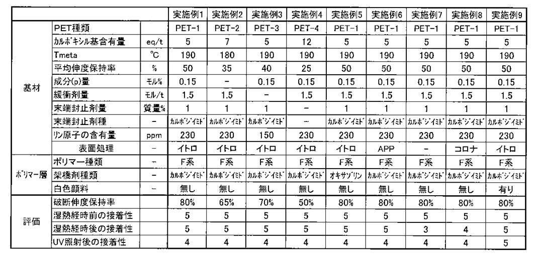

厚さ3mmの強化ガラスと、EVAシート(三井化学ファブロ(株)製のSC50B)と、結晶系太陽電池セルと、EVAシート(三井化学ファブロ(株)製のSC50B)と、実施例1の太陽電池用バックシートと、をこの順に重ね合わせ、真空ラミネータ(日清紡(株)製、真空ラミネート機)を用いてホットプレスすることにより、強化ガラス、太陽電池セル、及びバックシートを、それぞれEVAと接着させた。このとき、バックシートは、その反射層がEVAシートと接触するように配置した。
真空ラミネータを用いて、128℃で3分間の真空引き後、2分間加圧して仮接着した。その後、ドライオーブンにて150℃で30分間、本接着処理を施した。
実施例10において用いた太陽電池用バックシートを、実施例2~9で作製した太陽電池用バックシートに変更したこと以外は実施例10と同様にして結晶系の太陽電池モジュールを作製した。
実施例11~18のいずれの太陽電池モジュールも、太陽電池として良好な発電性能を示した。
本明細書に記述された全ての刊行物や特許出願、並びに技術標準は、それら個々の刊行物や特許出願、並びに技術標準が引用文献として特別に、そして個々に組み込むことが指定されている場合には、該引用文献と同じ限定範囲においてここに組み込まれるものである。本発明の範囲は下記特許請求の範囲及びその等価物に拠って決定されることを企図するものである。
Claims (15)
- 太陽電池素子が封止材で封止された電池側基板の前記封止材と接触させて配置される太陽電池用バックシートであって、
ポリエステルフィルム基材と、前記ポリエステルフィルム基材上に設けられた少なくとも1層のポリマー層とを有し、
前記ポリエステルフィルム基材は、末端カルボキシル基濃度が1eq/ton以上15eq/ton以下であり、示差走査熱量測定により求められる微小吸熱ピーク温度Tmeta(℃)が220℃以下であり、温度125℃、相対湿度100%RHの条件下で72時間放置した後の平均伸度保持率が10%以上のポリエステルフィルム基材であり、
前記ポリマー層の少なくとも1層は、少なくともフッ化炭素系ポリマーを含有し且つカルボジイミド系化合物及びオキサゾリン系化合物から選ばれる少なくとも1種の架橋剤由来の架橋構造を有し、且つ塗布により形成されたポリマー層である太陽電池用バックシート。 - 前記ポリエステルフィルム基材が、ジカルボン酸構成成分、ジオール構成成分、及び、カルボキシル基数(a)と水酸基数(b)との合計(a+b)が3以上である構成成分(p)を有するポリエステルを含み、前記構成成分(p)の含有量が、ポリエステルに含まれる全構成成分に対して0.005モル%以上2.5モル%以下である請求項1に記載の太陽電池用バックシート。
- 前記ポリエステルフィルム基材に含まれるポリエステルの全質量に対して、緩衝剤を0.1モル/ton以上5.0モル/ton以下の範囲で含有する請求項1に記載の太陽電池用バックシート。
- 前記ポリエステルフィルム基材に含まれるポリエステルの全質量に対して、カルボジイミド化合物である末端封止剤を0.1質量%以上5質量%以下の範囲で含有する請求項1に記載の太陽電池用バックシート。
- 前記ポリエステルフィルム基材における蛍光X線測定により求められるリン原子の含有量が200ppm以上である請求項1に記載の太陽電池用バックシート。
- 前記ポリエステルフィルム基材は、表面処理が施されている請求項1~請求項5のいずれか1項に記載の太陽電池用バックシート。
- 前記表面処理は、シラン化合物を導入した火炎を用いる火炎処理及び大気圧プラズマ処理から選ばれる少なくとも1つの表面処理である請求項6に記載の太陽電池用バックシート。
- 前記少なくともフッ素系ポリマーを含有し且つカルボジイミド系化合物及びオキサゾリン系化合物から選ばれる少なくとも1種の架橋剤由来の架橋構造を有するポリマー層が、前記ポリエステルフィルム基材における表面処理が施された面に直接接している請求項6に記載の太陽電池用バックシート。
- 前記少なくともフッ素系ポリマーを含有し且つカルボジイミド系化合物及びオキサゾリン系化合物から選ばれる少なくとも1種の架橋剤由来の架橋構造を有するポリマー層が、最外層である請求項1~請求項5のいずれか1項に記載の太陽電池用バックシート。
- 前記ポリマー層の少なくとも1層は、白色系顔料を含み、光反射性を有する反射層である請求項1~請求項5のいずれか1項に記載の太陽電池用バックシート。
- 末端カルボキシル基濃度が1eq/ton以上15eq/ton以下であり、示差走査熱量測定により求められる微小吸熱ピーク温度Tmeta(℃)が220℃以下であり、温度125℃、相対湿度100%RHの条件下で72時間放置した後の平均伸度保持率が10%以上のポリエステルフィルム基材上に、少なくともフッ素系ポリマーとカルボジイミド系化合物及びオキサゾリン系化合物から選ばれる少なくとも1種の架橋剤とを含有する塗布液を塗布する工程を含む太陽電池用バックシートの製造方法。
- 前記ポリエステルフィルム基材における前記塗布液が塗布される面上に、シラン化合物を導入した火炎を用いる火炎処理及び大気圧プラズマ処理から選ばれる少なくとも1つの表面処理を施す工程を含む請求項11に記載の太陽電池用バックシートの製造方法。
- 前記塗布液は、更に溶媒を含有し、該溶媒の50質量%以上が水である請求項11記載の太陽電池用バックシートの製造方法。
- 請求項1~請求項5のいずれか1項に記載の太陽電池用バックシート、又は請求項11~請求項13のいずれか1項に記載の太陽電池用バックシートの製造方法により製造された太陽電池用バックシートを備えた太陽電池モジュール。
- 更に、太陽光が入射する透明性のフロント基板と、
前記フロント基板の上に設けられ、太陽電池素子及び前記太陽電池素子を封止する封止材を有するセル構造部分と、を備え、
請求項14に記載の前記太陽電池モジュールに備えられる前記太陽電池用バックシートの少なくとも1つが、
前記セル構造部分の前記フロント基板が位置する側と反対側に設けられ、前記封止材と隣接して配置された、
請求項14に記載の太陽電池モジュール。
Priority Applications (3)
| Application Number | Priority Date | Filing Date | Title |
|---|---|---|---|
| KR1020137023949A KR101511201B1 (ko) | 2011-03-25 | 2012-03-01 | 태양전지용 백시트와 그 제조 방법, 및 태양전지 모듈 |
| CN201280013056.XA CN103443933B (zh) | 2011-03-25 | 2012-03-01 | 太阳能电池用背板及其制造方法、以及太阳能电池模块 |
| US14/018,933 US20130340830A1 (en) | 2011-03-25 | 2013-09-05 | Solar cell backsheet, producing method of the same, and solar cell module |
Applications Claiming Priority (2)
| Application Number | Priority Date | Filing Date | Title |
|---|---|---|---|
| JP2011-068809 | 2011-03-25 | ||
| JP2011068809A JP5587230B2 (ja) | 2011-03-25 | 2011-03-25 | 太陽電池用バックシート及びその製造方法、並びに太陽電池モジュール |
Related Child Applications (1)
| Application Number | Title | Priority Date | Filing Date |
|---|---|---|---|
| US14/018,933 Continuation US20130340830A1 (en) | 2011-03-25 | 2013-09-05 | Solar cell backsheet, producing method of the same, and solar cell module |
Publications (1)
| Publication Number | Publication Date |
|---|---|
| WO2012132756A1 true WO2012132756A1 (ja) | 2012-10-04 |
Family
ID=46930503
Family Applications (1)
| Application Number | Title | Priority Date | Filing Date |
|---|---|---|---|
| PCT/JP2012/055282 Ceased WO2012132756A1 (ja) | 2011-03-25 | 2012-03-01 | 太陽電池用バックシート及びその製造方法、並びに太陽電池モジュール |
Country Status (5)
| Country | Link |
|---|---|
| US (1) | US20130340830A1 (ja) |
| JP (1) | JP5587230B2 (ja) |
| KR (1) | KR101511201B1 (ja) |
| CN (1) | CN103443933B (ja) |
| WO (1) | WO2012132756A1 (ja) |
Cited By (3)
| Publication number | Priority date | Publication date | Assignee | Title |
|---|---|---|---|---|
| US20150027530A1 (en) * | 2012-02-23 | 2015-01-29 | Kolon Industries, Inc. | Solar module back sheet, and method for manufacturing same |
| CN105074939A (zh) * | 2013-04-17 | 2015-11-18 | 美国圣戈班性能塑料公司 | 用于光伏应用的多层层合物 |
| WO2016146982A1 (en) * | 2015-03-13 | 2016-09-22 | Dupont Teijin Films U.S. Limited Partnership | Pv cells and backsheet polyester films |
Families Citing this family (11)
| Publication number | Priority date | Publication date | Assignee | Title |
|---|---|---|---|---|
| JP5905353B2 (ja) * | 2011-08-25 | 2016-04-20 | 富士フイルム株式会社 | ポリエステルフィルム及びその製造方法、太陽電池用バックシート、並びに太陽電池モジュール |
| FR3017072B1 (fr) * | 2014-01-31 | 2016-02-19 | Toray Films Europ | Film de polyester transparent multicouche, son procede de fabrication et son utilisation notamment dans les faces arrieres de panneaux photovoltaiques |
| JP6097236B2 (ja) * | 2014-02-28 | 2017-03-15 | 富士フイルム株式会社 | 環状オレフィン系フィルム、光学フィルム、導電性フィルム、プリンテッドエレクトロニクス用基材フィルム、バリアフィルム、タッチパネル、偏光板および表示装置 |
| CN104934494A (zh) * | 2014-03-21 | 2015-09-23 | 3M创新有限公司 | 太阳能电池用复合背板和包含它的太阳能电池组件 |
| CN106574067B (zh) * | 2014-07-31 | 2020-01-10 | 富士胶片株式会社 | 层叠聚酯膜及其制造方法、太阳电池用保护片及太阳电池模块 |
| KR20180097590A (ko) * | 2015-12-28 | 2018-08-31 | 니폰 제온 가부시키가이샤 | 광학 적층체, 편광판 및 액정 표시 장치 |
| KR102037422B1 (ko) * | 2017-05-04 | 2019-10-28 | 에스케이씨 주식회사 | 태양전지 백시트용 폴리에스테르 필름 및 이를 포함하는 태양전지 모듈 |
| CN112055470B (zh) * | 2020-09-15 | 2021-05-25 | 简胜坚 | 一种利用光反射感应电路基板的节能环保处理装置 |
| CN112666065A (zh) * | 2020-11-20 | 2021-04-16 | 中国建材检验认证集团枣庄有限公司 | 光伏玻璃板封装材料eva胶膜模拟环境损伤的方法 |
| CN112408763B (zh) * | 2020-11-23 | 2021-11-05 | 徐州创合新材料科技有限公司 | 一种可钢化玻璃隔热涂层及其制备方法 |
| US11308257B1 (en) | 2020-12-15 | 2022-04-19 | International Business Machines Corporation | Stacked via rivets in chip hotspots |
Citations (2)
| Publication number | Priority date | Publication date | Assignee | Title |
|---|---|---|---|---|
| JP2010232201A (ja) * | 2009-03-25 | 2010-10-14 | Lintec Corp | 太陽電池モジュール用保護シート |
| JP2010238713A (ja) * | 2009-03-30 | 2010-10-21 | Lintec Corp | 太陽電池モジュール用保護シート及び太陽電池モジュール並びに太陽電池モジュールの製造方法 |
Family Cites Families (28)
| Publication number | Priority date | Publication date | Assignee | Title |
|---|---|---|---|---|
| US5391855A (en) * | 1991-08-01 | 1995-02-21 | Komoto Tech, Inc. | Apparatus for atmospheric plasma treatment of a sheet-like structure |
| JP3365366B2 (ja) * | 1999-09-06 | 2003-01-08 | ダイキン工業株式会社 | 架橋性含フッ素樹脂水性分散液組成物 |
| US6784248B2 (en) * | 2002-02-15 | 2004-08-31 | Ppg Industries Ohio, Inc. | Thermosetting compositions containing alternating copolymers of isobutylene type monomers |
| CN101155873A (zh) * | 2005-03-08 | 2008-04-02 | 因维斯塔技术有限公司 | 具有高尺寸稳定性的聚酯组合物 |
| US20060222907A1 (en) * | 2005-03-29 | 2006-10-05 | Imation Corp. | Magnetic recording medium having an atmospheric plasma modified substrate |
| JP5127123B2 (ja) * | 2005-07-22 | 2013-01-23 | ダイキン工業株式会社 | 太陽電池のバックシート |
| US20080264484A1 (en) * | 2007-02-16 | 2008-10-30 | Marina Temchenko | Backing sheet for photovoltaic modules and method for repairing same |
| JPWO2009125701A1 (ja) | 2008-04-08 | 2011-08-04 | 東レ株式会社 | 太陽電池用熱可塑性樹脂シートおよびその製造方法、太陽電池 |
| JP5594143B2 (ja) * | 2008-10-09 | 2014-09-24 | 旭硝子株式会社 | 水性塗料用組成物およびその製造方法、塗膜の製造方法 |
| MY179256A (en) * | 2009-03-26 | 2020-11-03 | Toray Industries | Polyester film for solar cells, solar cell back sheet using the same, and solar cell |
| JP5565020B2 (ja) * | 2009-03-27 | 2014-08-06 | 東レ株式会社 | ポリエステルフィルム、およびそれを用いた太陽電池 |
| KR101236016B1 (ko) * | 2009-04-08 | 2013-02-21 | 주식회사 엘지화학 | 태양전지 백시트 및 이의 제조방법 |
| EP2453485A1 (en) * | 2009-07-09 | 2012-05-16 | LINTEC Corporation | Protective sheet for solar cell module |
| JP2011029397A (ja) | 2009-07-24 | 2011-02-10 | Fujifilm Corp | 太陽電池用バックシート及びその製造方法 |
| JP2011040654A (ja) | 2009-08-17 | 2011-02-24 | Sumitomo Chemical Co Ltd | 太陽電池用バックシートおよび太陽電池モジュール |
| WO2011030896A1 (ja) * | 2009-09-14 | 2011-03-17 | 三菱樹脂株式会社 | 太陽電池裏面封止用二軸配向ポリエステルフィルム |
| JP5606956B2 (ja) * | 2010-02-23 | 2014-10-15 | 富士フイルム株式会社 | 太陽電池用バックシート及びその製造方法、並びに太陽電池モジュール |
| JP2011178866A (ja) * | 2010-02-26 | 2011-09-15 | Fujifilm Corp | ポリエステルフィルム及びその製造方法、並びに太陽電池裏面封止用ポリエステルフィルム、太陽電池裏面保護膜及び太陽電池モジュール |
| JP5283648B2 (ja) * | 2010-03-04 | 2013-09-04 | 富士フイルム株式会社 | ポリエステルフィルム及びその製造方法、並びに太陽電池モジュール |
| JP5705643B2 (ja) * | 2010-05-17 | 2015-04-22 | 富士フイルム株式会社 | 太陽電池用バックシート用ポリマーシート、及び太陽電池モジュール |
| JP5815276B2 (ja) * | 2010-05-19 | 2015-11-17 | 富士フイルム株式会社 | 太陽電池用バックシート用ポリマーシート及びその製造方法並びに太陽電池モジュール |
| US20120048348A1 (en) * | 2010-08-26 | 2012-03-01 | Fujifilm Corporation | Solar cell protective sheet and its production method, backsheet for solar cell, and solar cell module |
| JP5702116B2 (ja) * | 2010-11-09 | 2015-04-15 | 富士フイルム株式会社 | 太陽電池保護シート及びその製造方法、太陽電池用バックシート、並びに太陽電池モジュール |
| WO2012063945A1 (ja) * | 2010-11-12 | 2012-05-18 | 富士フイルム株式会社 | 太陽電池用バックシート及び太陽電池モジュール |
| JP5484293B2 (ja) * | 2010-11-12 | 2014-05-07 | 富士フイルム株式会社 | 太陽電池用バックシート及びその製造方法、並びに太陽電池モジュール |
| JP5623952B2 (ja) * | 2011-03-25 | 2014-11-12 | 富士フイルム株式会社 | 太陽電池用ポリマーシート及びその製造方法、太陽電池用バックシート、並びに太陽電池モジュール |
| TWI541313B (zh) * | 2011-08-31 | 2016-07-11 | 富士軟片股份有限公司 | 太陽電池用背板及太陽電池模組 |
| JP2015057814A (ja) * | 2013-05-31 | 2015-03-26 | 富士フイルム株式会社 | 太陽電池用バックシート及び太陽電池モジュール |
-
2011
- 2011-03-25 JP JP2011068809A patent/JP5587230B2/ja not_active Expired - Fee Related
-
2012
- 2012-03-01 KR KR1020137023949A patent/KR101511201B1/ko not_active Expired - Fee Related
- 2012-03-01 CN CN201280013056.XA patent/CN103443933B/zh active Active
- 2012-03-01 WO PCT/JP2012/055282 patent/WO2012132756A1/ja not_active Ceased
-
2013
- 2013-09-05 US US14/018,933 patent/US20130340830A1/en not_active Abandoned
Patent Citations (2)
| Publication number | Priority date | Publication date | Assignee | Title |
|---|---|---|---|---|
| JP2010232201A (ja) * | 2009-03-25 | 2010-10-14 | Lintec Corp | 太陽電池モジュール用保護シート |
| JP2010238713A (ja) * | 2009-03-30 | 2010-10-21 | Lintec Corp | 太陽電池モジュール用保護シート及び太陽電池モジュール並びに太陽電池モジュールの製造方法 |
Cited By (6)
| Publication number | Priority date | Publication date | Assignee | Title |
|---|---|---|---|---|
| US20150027530A1 (en) * | 2012-02-23 | 2015-01-29 | Kolon Industries, Inc. | Solar module back sheet, and method for manufacturing same |
| US9833943B2 (en) * | 2012-02-23 | 2017-12-05 | Kolon Industries, Inc. | Back sheet for solar cell module and method for manufacturing the same |
| CN105074939A (zh) * | 2013-04-17 | 2015-11-18 | 美国圣戈班性能塑料公司 | 用于光伏应用的多层层合物 |
| CN105103301A (zh) * | 2013-04-17 | 2015-11-25 | 美国圣戈班性能塑料公司 | 用于光伏应用的多层层合物 |
| WO2016146982A1 (en) * | 2015-03-13 | 2016-09-22 | Dupont Teijin Films U.S. Limited Partnership | Pv cells and backsheet polyester films |
| US11646385B2 (en) | 2015-03-13 | 2023-05-09 | Dupont Teijin Films U.S. Limited Partnership | PV cells and backsheet polyester films |
Also Published As
| Publication number | Publication date |
|---|---|
| KR20140015360A (ko) | 2014-02-06 |
| KR101511201B1 (ko) | 2015-04-10 |
| CN103443933B (zh) | 2016-05-04 |
| US20130340830A1 (en) | 2013-12-26 |
| CN103443933A (zh) | 2013-12-11 |
| JP5587230B2 (ja) | 2014-09-10 |
| JP2012204675A (ja) | 2012-10-22 |
Similar Documents
| Publication | Publication Date | Title |
|---|---|---|
| JP5587230B2 (ja) | 太陽電池用バックシート及びその製造方法、並びに太陽電池モジュール | |
| JP5815276B2 (ja) | 太陽電池用バックシート用ポリマーシート及びその製造方法並びに太陽電池モジュール | |
| CN103765609B (zh) | 太阳电池用背板及太阳电池模组 | |
| JP5753110B2 (ja) | 太陽電池モジュール用裏面保護シート及び太陽電池モジュール | |
| JP5702116B2 (ja) | 太陽電池保護シート及びその製造方法、太陽電池用バックシート、並びに太陽電池モジュール | |
| JP5722287B2 (ja) | 太陽電池用バックシート及びその製造方法並びに太陽電池モジュール | |
| JP5623952B2 (ja) | 太陽電池用ポリマーシート及びその製造方法、太陽電池用バックシート、並びに太陽電池モジュール | |
| WO2013024892A1 (ja) | 太陽電池用バックシート及びその製造方法、並びに太陽電池モジュール | |
| JP5606849B2 (ja) | 太陽電池用バックシート用ポリマーシート及び太陽電池モジュール | |
| JP5763021B2 (ja) | 太陽電池用ポリマーシート及びその製造方法、並びに太陽電池モジュール | |
| US20140144503A1 (en) | Polymer sheet for solar cell, and solar cell module | |
| JP5562889B2 (ja) | 積層フィルム、太陽電池用バックシートおよび積層フィルムの製造方法 | |
| JP2013045980A (ja) | 太陽電池用ポリマーシート、及び、太陽電池モジュール | |
| JP5650681B2 (ja) | 太陽電池用裏面保護シートおよび太陽電池モジュール | |
| JP2015188015A (ja) | 太陽電池裏面保護用積層ポリエステルフィルム、太陽電池裏面保護シート、及び太陽電池モジュール | |
| CN103650162B (zh) | 太阳电池用聚合物片与其制造方法及太阳电池模组 | |
| WO2013115119A1 (ja) | 2軸延伸ポリエステルフィルム、太陽電池モジュール用バックシートおよび太陽電池モジュール |
Legal Events
| Date | Code | Title | Description |
|---|---|---|---|
| WWE | Wipo information: entry into national phase |
Ref document number: 201280013056.X Country of ref document: CN |
|
| 121 | Ep: the epo has been informed by wipo that ep was designated in this application |
Ref document number: 12763615 Country of ref document: EP Kind code of ref document: A1 |
|
| ENP | Entry into the national phase |
Ref document number: 20137023949 Country of ref document: KR Kind code of ref document: A |
|
| NENP | Non-entry into the national phase |
Ref country code: DE |
|
| 122 | Ep: pct application non-entry in european phase |
Ref document number: 12763615 Country of ref document: EP Kind code of ref document: A1 |