WO2012132581A1 - 回転処理装置 - Google Patents
回転処理装置 Download PDFInfo
- Publication number
- WO2012132581A1 WO2012132581A1 PCT/JP2012/053153 JP2012053153W WO2012132581A1 WO 2012132581 A1 WO2012132581 A1 WO 2012132581A1 JP 2012053153 W JP2012053153 W JP 2012053153W WO 2012132581 A1 WO2012132581 A1 WO 2012132581A1
- Authority
- WO
- WIPO (PCT)
- Prior art keywords
- processing
- rotation
- frame
- roll
- rolls
- Prior art date
- Legal status (The legal status is an assumption and is not a legal conclusion. Google has not performed a legal analysis and makes no representation as to the accuracy of the status listed.)
- Ceased
Links
Images







Classifications
-
- A—HUMAN NECESSITIES
- A61—MEDICAL OR VETERINARY SCIENCE; HYGIENE
- A61F—FILTERS IMPLANTABLE INTO BLOOD VESSELS; PROSTHESES; DEVICES PROVIDING PATENCY TO, OR PREVENTING COLLAPSING OF, TUBULAR STRUCTURES OF THE BODY, e.g. STENTS; ORTHOPAEDIC, NURSING OR CONTRACEPTIVE DEVICES; FOMENTATION; TREATMENT OR PROTECTION OF EYES OR EARS; BANDAGES, DRESSINGS OR ABSORBENT PADS; FIRST-AID KITS
- A61F13/00—Bandages or dressings; Absorbent pads
- A61F13/15—Absorbent pads, e.g. sanitary towels, swabs or tampons for external or internal application to the body; Supporting or fastening means therefor; Tampon applicators
- A61F13/15577—Apparatus or processes for manufacturing
- A61F13/15707—Mechanical treatment, e.g. notching, twisting, compressing, shaping
Definitions
- the present invention relates to a rotation processing apparatus.
- a rotation processing apparatus that performs processing such as cutting, heat sealing, pressing, and embossing on a non-woven fabric or plastic sheet is known (see Patent Document 1).
- This rotation processing apparatus is formed as a unit including a frame and a pair of processing rolls rotatably supported by the frame.
- a roll corresponding to the process to be performed is selected and used as the process roll. That is, for example, in the case of a rotary cutting device that cuts a processed sheet into a predetermined cutting pattern, a cutting roll corresponding to the cutting pattern is selected and used. Therefore, when the cutting pattern is to be changed, the cutting roll is replaced with another cutting roll. Alternatively, when the processing roll is worn out, the processing roll is replaced with a new roll.
- this separate unit includes a processing roll and a frame that do not need to be replaced, there is a possibility that a large cost is required for replacing the processing roll. Further, a special configuration is required in which a roller is provided on the beam.
- a rotation processing apparatus a frame, a pair of processing rolls, and an attachment for attaching the processing rolls to the frame so as to be rotatable about rotation axes substantially parallel to each other and to be removable from the frame.
- a rotation processing apparatus is provided which is processed by these processing rolls.
- Processing roll replacement can be performed at low cost and with a simple configuration.
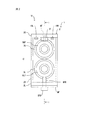
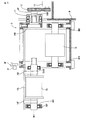
- FIG. 3 is a longitudinal sectional view of the rotation processing device taken along line ii in FIG. 2. It is a front end view of a rotation processing apparatus. It is a figure explaining a spacer. It is a figure explaining a tension regulator. It is a figure explaining the exchange effect
- FIG. 9 is a longitudinal sectional view taken along line ix-ix in FIG. 8. It is a longitudinal cross-sectional view similar to FIG. 1 which shows another Example by this invention.
- FIG. 1 and 2 show a case where the present invention is applied to a rotation processing apparatus incorporated in an absorbent article manufacturing apparatus.
- the rotation processing device is for performing processing such as cutting processing, heat sealing processing, pressing processing, and embossing processing on a processed sheet formed of a nonwoven fabric, plastic, or a combination thereof.
- the absorbent article includes sanitary napkins, absorbent pads, diapers and the like.
- the present invention is applied to a rotation processing apparatus for other uses.
- the factory equipment is provided with an end plate M that extends in the vertical direction, and the rotation processing device 1 is installed on the front receiving base MF that extends in the horizontal direction on the front side or operator side F of the end plate M. Is done.
- the rotation processing apparatus 1 includes a frame 2 and a pair of processing rolls 3U and 3L.
- the frame 2 has a rectangular parallelepiped shape as a whole, and includes an upper horizontal portion 2U, a lower horizontal portion 2L, and a vertical portion 2V.
- each of the upper horizontal portion 2U and the lower horizontal portion 2L includes four rod-like members that extend in the horizontal direction and are aligned in a square shape, and the vertical portion 2V extends in the vertical direction. And four bar-like members connecting the upper horizontal portion 2U and the lower horizontal portion 2L to each other.
- the processing rolls 3U and 3L are attached to the frame 2 so as to be rotatable about rotation axes AU and AL that are substantially parallel to each other and to be removable from the frame 2.
- the processing roll 3U includes a main body 3UB including a pair of flanges 3UF and 3UF, and a pair of shafts 3USF and 3USB.
- Corresponding bearings 4UF and 4UB are attached to the shafts 3USF and 3USB, respectively, and the bearings 4UF and 4UB are accommodated in the corresponding bearing cases 5UF and 5UB, respectively.
- the bearing cases 5UF and 5UB are removably attached to the frame 2, for example, the upper horizontal portion 2U, by corresponding fixing members, for example, bolts 6F and 6B.
- spacers 7F and 7B are provided between the frame 2 and the bearing cases 5UF and 5UB, respectively. As shown in FIG. 3, the spacers 7F and 7B have a notch 7C, and bolts 6F and 6B extend in the notch 7C.
- the processing roll 3L includes a main body 3LB and a pair of shafts 3LSF and 3LSB.
- Corresponding bearings 4LF and 4LB are attached to the outer peripheral surfaces of the shafts 3LSF and 3LSB, and the bearings 4LF and 4LB are accommodated in the corresponding bearing cases 5LF and 5LB, respectively.
- the bearing cases 5LF and 5LB are supported by the actuator 8, respectively.
- the actuator 8 includes a pair of hydraulic cylinders 8F and 8B.
- the hydraulic cylinders 8F and 8B are respectively provided with main bodies 8FB and 8BB and rods 8FR and 8BR that can advance and retract in the vertical direction.
- the main bodies 8FB and 8BB are attached to the lower surface of the front receiving table MF, and the rods 8FR and 8BR extend from the main bodies 8FB and 8BB through the front receiving table MF and the lower horizontal portion 2L in the vertical direction.
- the above-described bearing cases 5LF and 5LB are supported on the rods 8FR and 8BR, respectively.
- the processing roll 3L When the rods 8FR and 8BR are moved forward, the processing roll 3L is brought into contact with the processing roll 3U, and when the rods 8FR and 8BR are moved backward, the processing roll 3L is separated from the processing roll 3U.
- the main bodies 8FB and 8BB are attached to the upper surface of the front cradle MF.
- bearing cases 5UF and 5UB and the bolts 6F and 6B constitute an attachment mechanism for detachably attaching the processing roll 3U to the frame 2.
- the bearing cases 5LF and 5LB and the actuator 8 constitute an attachment mechanism for detachably attaching the processing roll 3L to the frame 2.
- the rotation axes AU and AL extend in a substantially horizontal direction and are aligned in a substantially vertical direction.
- the processing roll 3U is a cutting roll which has a cutting blade
- the processing roll 3L is an anvil roll.
- the axial distance between the bearing cases 5UF and 5UB and the axial distance between the bearing cases 5LF and 5LB are respectively based on the axial distance between the bearings 4UF and 4UB and the axial distance between the bearings 4LF and 4LB. However, it is preferably slightly larger, for example, 0.01 mm. This is because the processing rolls 3U and 3L are thermally expanded.
- the drive mechanism 9 is detachably attached to the shaft 3USB behind the processing roll 3U.
- the drive mechanism 9 includes a pulley 9P having a connecting portion 9C.
- the tip of the shaft 3USB is received in the receiving portion 9CR of the connecting portion 9C.
- the axial protrusion formed on the shaft 3USB is received in the axial concave groove formed on the receiving portion 9CR.
- a pair of bearings 10 are attached to the outer peripheral surface of the connecting portion 9C of the pulley 9P, and the bearings 10 are accommodated in the bearing case 11.
- Bearing case 11 is fixed to bearing case 5UB.
- the pulley 9P is connected to the electric motor 13 through the belt 12.
- the electric motor 13 is installed on a rear receiving base MB that extends in the horizontal direction on the rear side of the end plate M.
- the drive mechanism 9 further includes a tension adjuster 15 that adjusts the tension of the belt 12.
- a notch MC is formed in the end plate M, and the pulley 9P protrudes rearward through the notch MC.
- a transfer mechanism 16 is attached to the frame 2.
- the transfer mechanism 16 includes a pair of transfer members 16L and 16R attached to the upper horizontal portion 2U of the frame 2 on both sides of the rotation axes AU and AL. These transfer members 16L and 16R are movable substantially along the rotation axes AU and AL.
- the transfer mechanism 16 further includes a holding member that holds the processing roll to be replaced on the transfer members 16L and 16R.
- the sheet to be processed is processed in the processing portion T between the processing rolls 3U and 3L.
- the sheet to be processed is conveyed along the conveyance surface C. Accordingly, the height H7 (FIG. 3) of the spacers 7F and 7B is selected so that the processing portion T substantially coincides with the conveyance surface C, the rods 8FR and 8BR are advanced, and the processing roll 3L contacts the processing roll 3U. Is done.
- Processing roll 3U is replaced as follows. That is, first, the operation of the electric motor 13 is stopped. Subsequently, the tension adjuster 15 reduces the tension of the belt 12.
- the rods 8FR and 8BR are retracted, and the processing roll 3L is moved away from the processing roll 3U.
- the holding members 16F and 16B are attached to the transfer members 16L and 16R so as to pass below the shafts 3USF and 3USB of the processing roll 3U.
- the holding members 16F and 16B are each constituted by a belt.
- the holding member is composed of a sheet, for example.
- the holding members 16F and 16B are attached to the transfer members 16L and 16R before the processing roll 3L is moved.
- the processing roll 3U is drawn forward substantially along the rotation axis AU and transferred to the outside of the frame 2 by the transfer members 16L and 16R.
- the pulley 9P is attached to the bearing case 5UB via the bearing case 11, it does not move, that is, separates from the processing roll 3U.
- the bearing case 5UF has been removed from the bearing 4UF in advance.
- the processing roll 3U is removed from the transfer members 16L and 16R.
- the new processing roll 3U is held by the transfer members 16L and 16R by the holding members 16F and 16B.
- a new processing roll 3U is transferred to the inside of the frame 2 by the transfer members 16L and 16R.
- the shaft 3USB is received in the receiving portion 9CR of the pulley 9P, and the bearing 4UB is received in the bearing case 5UB.
- the bolt 6F and the spacer 7F are attached, and thus the processing roll 3U is attached to the frame 2.
- the holding members 16F and 16B are detached from the transfer members 16L and 16R.
- the rods 8FR and 8BR are advanced, and the processing roll 3L is brought into contact with the new processing roll 3U.
- the tension adjuster 15 increases the tension of the belt 12 to an appropriate value.
- the processing roll 3U can be replaced at a low cost with a simple configuration. That is, only the processing roll 3U to be replaced can be taken out without replacing the frame 2 and the processing roll 3L. As a result, it is not necessary to prepare a spare frame or the like. Further, a space for storing spare frames is not required.
- FIG. 7 shows a case where the diameter of the new processing roll 3U is small.
- the spacers 7F and 7B are replaced with ones having a large height H7 (FIG. 3). This means that the height position of the pulley 9P is changed.
- the tension adjuster 15 is operated by an operator operating the operator, and this operator is preferably provided on the front side of the end plate M.
- the transfer mechanism 16 includes a single transfer member 20 attached to the lower horizontal portion 2L of the frame 2 substantially along the rotation axis AU, AL, and a processing roll 3L to be replaced. And holding members 20F and 20B for holding the transfer member 20 on the transfer member 20.
- the transfer member 20 is movable substantially along the rotation axes AU and AL.
- the processing roll 3U is exchanged in the same manner as in the embodiment shown in FIGS.
- the processing roll 3L is replaced as follows. That is, first, the operation of the electric motor 13 is stopped. Subsequently, the tension adjuster 15 reduces the tension of the belt 12.
- the rods 8FR and 8BR are retracted.
- the shafts 3LSF and 3LSB of the processing roll 3L are received and held by the holding members 20F and 20B. That is, the processing roll 3L is detached from the rods 8FR and 8BR, and is thus removed from the frame 2.
- the processing roll 3L is drawn forward substantially along the rotation axis AL by the transfer member 20, and transferred to the outside of the frame 2.
- the processing roll 3L is removed from the holding members 20F and 20B.
- a new processing roll 3L is held by the holding members 20F and 20B.
- a new processing roll 3 ⁇ / b> L is transferred to the inside of the frame 2 by the transfer member 20.
- the rods 8FR and 8BR are advanced, and the processing roll 3L is brought into contact with the new processing roll 3U.
- the tension adjuster 15 increases the tension of the belt 12 to an appropriate value.
- the processing roll 3L can be replaced at a low cost with a simple configuration.
- the pulley 9P is connected to the electric motor 13 via the belt 12.
- the pulley 9 ⁇ / b> P is directly connected to the electric motor 13.
- the pulley 9P and the electric motor 13 together with the processing roll 3 can be moved along the axis AU.
Landscapes
- Health & Medical Sciences (AREA)
- Engineering & Computer Science (AREA)
- Heart & Thoracic Surgery (AREA)
- Manufacturing & Machinery (AREA)
- Epidemiology (AREA)
- Biomedical Technology (AREA)
- Mechanical Engineering (AREA)
- Vascular Medicine (AREA)
- Life Sciences & Earth Sciences (AREA)
- Animal Behavior & Ethology (AREA)
- General Health & Medical Sciences (AREA)
- Public Health (AREA)
- Veterinary Medicine (AREA)
- Absorbent Articles And Supports Therefor (AREA)
- Shaping Of Tube Ends By Bending Or Straightening (AREA)
Abstract
処理ロールの交換を安価にかつ簡単に行うために、回転処理装置(1)は、フレーム(2)と、一対の処理ロール(3U,3L)と、これら処理ロール(3U,3L)をフレーム(2)に対し、互いにほぼ平行な回転軸線(AU,AL)回りに回転可能に、かつフレーム(2)から取り外し可能に取り付ける取り付け機構(9)と、フレーム(2)から取り外された処理ロール(3U,3L)を受け取ると共に、処理ロール(3U,3L)を回転軸線(AU,AL)にほぼ沿ってフレーム(2)外に移送するための移送機構(16)と、を具備する。処理ロール(3U,3L)間に供給された被処理物はこれら処理ロール(3U,3L)によって処理される。
Description
本発明は回転処理装置に関する。
例えば吸収性物品を製造するために、不織布又はプラスチックの被処理シートに、切断、ヒートシール加工、プレス加工、エンボス加工といった処理を施す回転処理装置が公知である(特許文献1参照)。この回転処理装置は、フレームと、フレームに回転可能に支持された一対の処理ロールとを備えるユニットとして形成される。
ところで、処理ロールとして、行うべき処理に応じたロールが選択され、使用される。すなわち、例えば被処理シートをあらかじめ定められた切断パターンに切断する回転切断装置の場合、切断パターンに応じた切断ロールが選択され、使用される。したがって、切断パターンを変更すべきときには、切断ロールが別の切断ロールに交換される。あるいは、処理ロールが摩耗等した場合には、処理ロールが新品のロールに交換される。
このような処理ロールの交換のために、特許公報1の回転処理装置では、ユニット全体が交換される。また、ユニット交換のために、ユニットを支持する梁にローラが設けられる。
しかしながら、このようにユニット全体を交換する場合には、別ユニットを用意する必要がある。この別ユニットには、交換する必要がない処理ロールやフレーム等が含まれるので、処理ロールの交換のために大きなコストを要するおそれがある。また、梁にローラを設けるといった特別な構成が必要となる。
本発明によれば、回転処理装置であって、フレームと、一対の処理ロールと、これら処理ロールをフレームに対し、互いにほぼ平行な回転軸線回りに回転可能に、かつフレームから取り外し可能に取り付ける取り付け機構と、フレームから取り外された処理ロールを受け取ると共に、該処理ロールを回転軸線にほぼ沿ってフレーム外に移送するための移送機構と、を具備し、処理ロール間に供給された被処理物がこれら処理ロールによって処理される、回転処理装置が提供される。
処理ロールの交換を安価にかつ簡単な構成でもって行うことができる。
図1及び図2は、吸収性物品製造装置に組み込まれる回転処理装置に本発明を適用した場合を示している。この場合、回転処理装置は、不織布、プラスチック、又はこれらの組み合わせから構成される被処理シートに切断加工、ヒートシール加工、プレス加工、エンボス加工といった処理を施すためのものである。ここで、吸収性物品には生理用ナプキン、吸収パッド、オムツ等が含まれる。別の例では、本発明は他の用途の回転処理装置に適用される。
図1及び図2を参照すると、工場設備には鉛直方向に拡がる鏡板Mが設けられており、鏡板Mの前側ないし操作者側Fにおいて水平方向に拡がる前側受け台MFに回転処理装置1が設置される。この回転処理装置1は、フレーム2と、一対の処理ロール3U,3Lとを具備する。
フレーム2は、全体として直方体形状をなすと共に、上方水平部分2U、下方水平部分2L、及び鉛直部分2Vを含む。図1及び図2に示される例では、上方水平部分2U及び下方水平部分2Lはそれぞれ、水平方向に延びて四角形状に整列された4本の棒状部材を含み、鉛直部分2Vは鉛直方向に延びて上方水平部分2U及び下方水平部分2Lを互いに連結する4本の棒状部材を含む。
処理ロール3U,3Lはフレーム2に対し、互いにほぼ平行な回転軸線AU,AL回りに回転可能に、かつフレーム2から取り外し可能に取り付けられる。
すなわち、処理ロール3Uは、一対のフランジ3UF,3UFを含む本体3UBと、一対の軸3USF,3USBとを備える。これら軸3USF,3USBにはそれぞれ対応するベアリング4UF,4UBが取り付けられ、ベアリング4UF,4UBはそれぞれ対応するベアリングケース5UF,5UB内に収容される。ベアリングケース5UF,5UBはそれぞれ対応する固定具、例えばボルト6F,6Bによって、フレーム2、例えば上方水平部分2Uに取り外し可能に取り付けられる。
図1及び図2に示される例では、フレーム2とベアリングケース5UF,5UBとの間に、スペーサ7F,7Bがそれぞれ設けられる。スペーサ7F,7Bは図3に示されるように、切欠き7Cを有し、この切欠き7C内をボルト6F,6Bが延びる。
再び図1及び図2を参照すると、処理ロール3Lは、本体3LBと、一対の軸3LSF,3LSBとを備える。これら軸3LSF,3LSBの外周面にはそれぞれ対応するベアリング4LF,4LBが取り付けられ、ベアリング4LF,4LBはそれぞれ対応するベアリングケース5LF,5LB内に収容される。ベアリングケース5LF,5LBはそれぞれアクチュエータ8に支持される。
図1及び図2に示される実施例では、アクチュエータ8は一対の油圧シリンダ8F,8Bを備え、これら油圧シリンダ8F,8Bはそれぞれ、本体8FB,8BBと、鉛直方向に進退可能なロッド8FR,8BRとを備える。本体8FB,8BBは前側受け台MFの下面に取り付けられ、ロッド8FR,8BRは本体8FB,8BBから前側受け台MF及び下方水平部分2Lを貫通して鉛直方向にそれぞれ延びる。上述のベアリングケース5LF,5LBはそれぞれロッド8FR,8BR上に支持される。ロッド8FR,8BRが前進されると処理ロール3Lが処理ロール3Uに当接され、ロッド8FR,8BRが後退されると処理ロール3Lが処理ロール3Uから離間される。別の例では、本体8FB,8BBは前側受け台MFの上面に取り付けられる。
ここで、ベアリングケース5UF,5UB及びボルト6F,6Bは処理ロール3Uをフレーム2に対し取り外し可能に取り付ける取り付け機構を構成する。また、ベアリングケース5LF,5LB及びアクチュエータ8は処理ロール3Lをフレーム2に対し取り外し可能に取り付ける取り付け機構を構成する。
図1及び図2に示される例では、回転軸線AU,ALは、ほぼ水平方向に延びると共に、ほぼ鉛直方向に整列される。なお、回転処理装置が回転切断装置から構成される場合には、処理ロール3Uは切断刃を有する切断ロールであり、処理ロール3Lはアンビルロールである。
ベアリングケース5UF,5UB同士の間の軸線方向距離及びベアリングケース5LF,5LB同士の間の軸線方向距離はそれぞれ、ベアリング4UF,4UB同士の間の軸線距離及びベアリング4LF,4LB同士の間の軸線距離よりもわずかに、例えば0.01mm大きいのが好ましい。処理ロール3U,3Lが熱膨張するからである。
処理ロール3Uの後方の軸3USBには、駆動機構9が着脱可能に取り付けられる。駆動機構9は、連結部分9Cを有するプーリ9Pを備える。図1及び図2に示される例では、軸3USBの先端が連結部分9Cの受容部分9CR内に受容される。この場合、軸3USBに形成される軸線方向の突起が受容部分9CRに形成される軸線方向の凹溝内に受容される。その結果、軸3USBすなわち処理ロール3Uは、プーリ9Pすなわち駆動機構9と共に軸線AU回りに回転可能であり、回転軸線AUに沿って駆動機構9から離脱可能である。
プーリ9Pの連結部分9Cの外周面には、一対のベアリング10が取り付けられ、ベアリング10はベアリングケース11内に収容される。ベアリングケース11はベアリングケース5UBに固定される。
プーリ9Pはベルト12を介して電気モータ13に連結される。この電気モータ13は鏡板Mの後側において水平方向に拡がる後側受け台MB上に設置される。駆動機構9は更に、図4に示されるように、ベルト12の張力を調節する張力調節器15を備える。
なお、鏡板Mには切欠きMCが形成されており、この切欠きMCを介してプーリ9Pが後方に突出している。
更に、フレーム2には、移送機構16が取り付けられる。移送機構16は、回転軸線AU,ALの両側においてフレーム2の上方水平部分2Uに取り付けられた一対の移送部材16L,16Rを備える。これら移送部材16L,16Rは回転軸線AU,ALにほぼ沿って移動可能である。移送機構16は更に、交換すべき処理ロールを移送部材16L,16Rに保持する保持部材を備える。
さて、被処理シートは処理ロール3U,3L同士の間の処理部分Tにおいて処理される。一方、被処理シートは搬送面Cに沿って搬送される。したがって、処理部分Tが搬送面Cにほぼ一致するように、スペーサ7F,7Bの高さH7(図3)が選択され、ロッド8FR,8BRが前進されて処理ロール3Lが処理ロール3Uに当接される。
その上で、電気モータ13が駆動されると、処理ロール3Uが回転軸線AU回りに回転され、処理ロール3Uに当接する処理ロール3Lが処理ロール3Uとの摩擦により回転軸線AL回りに回転される。
処理ロール3Uは次のようにして交換される。すなわち、まず、電気モータ13の運転が停止される。次いで、張力調節器15により、ベルト12の張力が弱められる。
次いで、図5及び図6に示されるように、ロッド8FR,8BRが後退され、処理ロール3Lが処理ロール3Uから離脱するよう移動される。次いで、処理ロール3Uの軸3USF,3USBの下方を通るように、移送部材16L,16Rに保持部材16F,16Bが取り付けられる。この場合、保持部材16F,16Bはそれぞれベルトから構成される。別の例では、保持部材は例えばシートから構成される。また、更に別の例では、処理ロール3Lの移動の前に、保持部材16F,16Bが移送部材16L,16Rに取り付けられる。
次いで、前方のボルト6F及び前方のスペーサ7Fが取り外される。次いで、移送部材16L,16Rにより、処理ロール3Uが回転軸線AUにほぼ沿って、前方に引き出され、フレーム2の外部まで移送される。この場合、プーリ9Pは、ベアリングケース11を介してベアリングケース5UBに取り付けられているので、移動せず、すなわち、処理ロール3Uから離脱する。別の例では、ベアリングケース5UFはあらかじめベアリング4UFから取り外されている。
次いで、処理ロール3Uが移送部材16L,16Rから取り外される。次いで、新たな処理ロール3Uが保持部材16F,16Bにより移送部材16L,16Rに保持される。次いで、移送部材16L,16Rにより、新たな処理ロール3Uがフレーム2の内部まで移送される。次いで、軸3USBがプーリ9Pの受容部分9CR内に受容され、ベアリング4UBがベアリングケース5UB内に収容される。次いでボルト6F及びスペーサ7Fが取り付けられ、したがって処理ロール3Uがフレーム2に対し取り付けられる。次いで、保持部材16F,16Bが移送部材16L,16Rから取り外される。
次いで、ロッド8FR,8BRが前進され、処理ロール3Lが新たな処理ロール3Uに当接される。次いで、張力調節器15によりベルト12の張力が適切な値まで高められる。
このように本発明による実施例では、処理ロール3Uの交換を安価にかつ簡単な構成でもって行うことができる。すなわち、フレーム2及び処理ロール3Lを交換することなく、交換すべき処理ロール3Uのみを取り出すことができる。その結果、予備のフレーム等を用意する必要がない。また、予備のフレームを保管しておく空間も必要なくなる。
図7には、新たな処理ロール3Uの直径が小さい場合を示している。この場合、スペーサ7F,7Bが大きい高さH7(図3)のものに交換される。このことは、プーリ9Pの高さ位置が変更されることを意味している。しかしながら、本発明による実施例では、張力調節器15によってベルト12の張力が最適に維持されるので、電気モータ13の位置を変更する必要がない。なお、張力調節器15は操作者が操作器を操作することによって操作され、この操作器は鏡板Mの前側に設けられるのが好ましい。
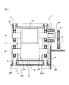
図8及び図9は本発明による別の実施例を示している。図8及び図9に示される例では、移送機構16は、回転軸線AU,ALにほぼ沿ってフレーム2の下方水平部分2Lに取り付けられた単一の移送部材20と、交換すべき処理ロール3Lを移送部材20に保持する保持部材20F,20Bと、を備える。移送部材20は回転軸線AU,ALにほぼ沿って移動可能である。
処理ロール3Uの交換は図1及び図2に示される実施例と同様に行われる。一方、処理ロール3Lは次のようにして交換される。すなわち、まず、電気モータ13の運転が停止される。次いで、張力調節器15により、ベルト12の張力が弱められる。
次いで、ロッド8FR,8BRが後退される。その結果、処理ロール3Lの軸3LSF,3LSBが保持部材20F,20Bに受け取られ、保持される。すなわち、処理ロール3Lがロッド8FR,8BRから離脱され、したがってフレーム2から取り外される。
次いで、移送部材20により、処理ロール3Lが回転軸線ALにほぼ沿って、前方に引き出され、フレーム2の外部まで移送される。
次いで、処理ロール3Lが保持部材20F,20Bから取り外される。次いで、新たな処理ロール3Lが保持部材20F,20Bにより保持される。次いで、移送部材20により、新たな処理ロール3Lがフレーム2の内部まで移送される。
次いで、ロッド8FR,8BRが前進され、処理ロール3Lが新たな処理ロール3Uに当接される。次いで、張力調節器15によりベルト12の張力が適切な値まで高められる。
このように、図8及び図9に示される例でも、処理ロール3Lの交換を安価にかつ簡単な構成でもって行うことができる。
これまで述べてきた実施例では、プーリ9Pはベルト12を介して電気モータ13に連結される。しかしながら図10に示される例では、プーリ9Pは電気モータ13に直接的に連結される。この場合、ボルト6F,6Bをベアリングケース5UF,5UBから取り外し、電気モータ13を受け台MBから取り外すと、処理ロール3と共にプーリ9P及び電気モータ13を軸線AUに沿って移動させることができる。
本願は日本特許出願第2011-072695号の利益を主張し、その開示全体はここに援用される。
1 回転処理装置
2 フレーム
3U,3L 処理ロール
9 取り付け機構
16 移送機構
16L,16R;20 移送部材
16F,16B;20F,20B 保持部材
2 フレーム
3U,3L 処理ロール
9 取り付け機構
16 移送機構
16L,16R;20 移送部材
16F,16B;20F,20B 保持部材
Claims (10)
- 回転処理装置であって、
フレームと、
一対の処理ロールと、
これら処理ロールをフレームに対し、互いにほぼ平行な回転軸線回りに回転可能に、かつフレームから取り外し可能に取り付ける取り付け機構と、
フレームから取り外された処理ロールを受け取ると共に、該処理ロールを回転軸線にほぼ沿ってフレーム外に移送するための移送機構と、
を具備し、
処理ロール間に供給された被処理物がこれら処理ロールによって処理される、
回転処理装置。 - 前記移送機構は、フレームに対し処理ロールの回転軸線にほぼ沿って移動可能な移送部材と、フレームから取り外された処理ロールを移送部材に保持する保持部材と、を具備する、請求項1に記載の回転処理装置。
- 前記移送部材は、処理ロールの回転軸線の両側においてフレームに移動可能に取り付けられた一対の移送部材を備える、請求項2に記載の回転処理装置。
- 前記移送部材は、処理ロールの回転軸線にほぼ沿ってフレームに移動可能に取り付けられた単一の移送部材を備える、請求項2に記載の回転処理装置。
- 処理ロールを回転させるために処理ロールに着脱可能に取り付けられた駆動機構を更に具備する、請求項1から4までのいずれか一項に記載の回転処理装置。
- 一方の処理ロールが、進退可能なロッドによって支持される、請求項1から5までのいずれか一項に記載の回転処理装置。
- 前記取り付け機構がボルトを含む、請求項1から6までのいずれか一項に記載の回転処理装置。
- 前記回転処理装置は、鏡板の前側において拡がる前側受け台に設置される、請求項1から7までのいずれか一項に記載の回転処理装置。
- 前記回転処理装置は、不織布、プラスチック、又はこれらの組み合わせから構成される被処理シートに切断加工、ヒートシール加工、プレス加工、又はエンボス加工を施すためのものである、請求項1から8までのいずれか一項に記載の回転処理装置。
- 前記回転処理装置は吸収性物品製造装置に組込まれている、請求項1から9までのいずれか一項に記載の回転処理装置。
Applications Claiming Priority (2)
| Application Number | Priority Date | Filing Date | Title |
|---|---|---|---|
| JP2011072695A JP5818478B2 (ja) | 2011-03-29 | 2011-03-29 | 回転処理装置 |
| JP2011-072695 | 2011-03-29 |
Publications (1)
| Publication Number | Publication Date |
|---|---|
| WO2012132581A1 true WO2012132581A1 (ja) | 2012-10-04 |
Family
ID=46930345
Family Applications (1)
| Application Number | Title | Priority Date | Filing Date |
|---|---|---|---|
| PCT/JP2012/053153 Ceased WO2012132581A1 (ja) | 2011-03-29 | 2012-02-10 | 回転処理装置 |
Country Status (2)
| Country | Link |
|---|---|
| JP (1) | JP5818478B2 (ja) |
| WO (1) | WO2012132581A1 (ja) |
Families Citing this family (5)
| Publication number | Priority date | Publication date | Assignee | Title |
|---|---|---|---|---|
| JP2552367Y2 (ja) | 1991-12-13 | 1997-10-29 | 石川島播磨重工業株式会社 | クラウン制御ロール |
| CN105899172A (zh) * | 2013-12-20 | 2016-08-24 | 宝洁公司 | 用于活动安装架转换加工机的模块化单元操作 |
| CN108601681B (zh) * | 2016-01-29 | 2019-07-30 | 尤妮佳股份有限公司 | 输送辊、具有输送辊的装置、以及输送方法 |
| ITUB20160592A1 (it) * | 2016-02-09 | 2017-08-09 | Gdm Spa | Unità di alimentazione di ali laterali di un articolo assorbente igienico e metodo di cambio formato dell’unità di alimentazione. |
| JP6932040B2 (ja) * | 2017-08-07 | 2021-09-08 | Mmcリョウテック株式会社 | ロータリーダイカッター |
Citations (7)
| Publication number | Priority date | Publication date | Assignee | Title |
|---|---|---|---|---|
| JPS63104365U (ja) * | 1986-12-23 | 1988-07-06 | ||
| JPH02274330A (ja) * | 1989-04-13 | 1990-11-08 | Kawakami Tekkosho:Kk | エンボス加工装置におけるエンボスロール交換装置 |
| JPH04210498A (ja) * | 1990-12-12 | 1992-07-31 | Kawasaki Steel Corp | 竪型タンクのロール組替装置 |
| JP2001232755A (ja) * | 2000-02-23 | 2001-08-28 | Man Roland Druckmas Ag | 印刷機の胴を取り付け及び取り外す方法並びにこの方法を実施する装置 |
| US7299729B2 (en) * | 2001-05-23 | 2007-11-27 | Cox William A | Rotary die module |
| JP2007536927A (ja) * | 2004-05-11 | 2007-12-20 | ストルク タイタン ベスローテン フェンノートシャップ | 成形機 |
| JP2008534309A (ja) * | 2005-04-07 | 2008-08-28 | サンドビック インテレクチュアル プロパティー アクティエボラーグ | 切削ドラム及びアンビルドラムを備える回転切削装置 |
-
2011
- 2011-03-29 JP JP2011072695A patent/JP5818478B2/ja not_active Expired - Fee Related
-
2012
- 2012-02-10 WO PCT/JP2012/053153 patent/WO2012132581A1/ja not_active Ceased
Patent Citations (7)
| Publication number | Priority date | Publication date | Assignee | Title |
|---|---|---|---|---|
| JPS63104365U (ja) * | 1986-12-23 | 1988-07-06 | ||
| JPH02274330A (ja) * | 1989-04-13 | 1990-11-08 | Kawakami Tekkosho:Kk | エンボス加工装置におけるエンボスロール交換装置 |
| JPH04210498A (ja) * | 1990-12-12 | 1992-07-31 | Kawasaki Steel Corp | 竪型タンクのロール組替装置 |
| JP2001232755A (ja) * | 2000-02-23 | 2001-08-28 | Man Roland Druckmas Ag | 印刷機の胴を取り付け及び取り外す方法並びにこの方法を実施する装置 |
| US7299729B2 (en) * | 2001-05-23 | 2007-11-27 | Cox William A | Rotary die module |
| JP2007536927A (ja) * | 2004-05-11 | 2007-12-20 | ストルク タイタン ベスローテン フェンノートシャップ | 成形機 |
| JP2008534309A (ja) * | 2005-04-07 | 2008-08-28 | サンドビック インテレクチュアル プロパティー アクティエボラーグ | 切削ドラム及びアンビルドラムを備える回転切削装置 |
Also Published As
| Publication number | Publication date |
|---|---|
| JP2012205695A (ja) | 2012-10-25 |
| JP5818478B2 (ja) | 2015-11-18 |
Similar Documents
| Publication | Publication Date | Title |
|---|---|---|
| WO2012132581A1 (ja) | 回転処理装置 | |
| JP5590899B2 (ja) | ロータリ加工装置 | |
| JP6393456B2 (ja) | 切断ユニット | |
| JP6929739B2 (ja) | 特にレーザー式管切断機のような管加工機において管を支持する支持装置、及びそのような支持装置を備える管加工機 | |
| JP5032014B2 (ja) | ワークサポートのサポートストリップを洗浄するための機械的な装置 | |
| CN103143995B (zh) | 钛管内壁抛光机 | |
| CZ282492B6 (cs) | Válcovací stolice | |
| JP2010269401A (ja) | スリッター装置 | |
| US9662799B2 (en) | Band saw | |
| CN103167933A (zh) | 用于对轮组轴进行滚压的机床 | |
| ES2906839T3 (es) | Dispositivo de gofrado con unidad de almacenamiento de rodillos de gofrado | |
| ITMO20100117A1 (it) | Dispositivo per rifinire bordi e/o superfici esterne di pezzi da lavorare | |
| JP6230188B2 (ja) | 加圧装置 | |
| JPH03174908A (ja) | インナーハウジング式複数ロール圧延機 | |
| JP6693978B2 (ja) | 搬送用ツールおよびロボット | |
| ES2893467T3 (es) | Dispositivo y procedimiento de conformación | |
| KR101611719B1 (ko) | 소재 이송장치 및 이를 포함하는 절단기 | |
| CN119332404A (zh) | 一种牵引力动态调整的罗拉装置及其方法 | |
| CN219093413U (zh) | 一种无缝钢管的夹持旋转机构 | |
| JP5932115B1 (ja) | ローラ支持用ブラケット調整機構およびレール走行車両 | |
| JP2010184269A (ja) | 回転型塑性加工装置 | |
| KR102278430B1 (ko) | 롤 교체 장치 | |
| JP2008246589A (ja) | 複列転走面の同時超仕上げ加工装置 | |
| CN113664366A (zh) | 一种具有焊前焊后同步清理的激光焊接装置 | |
| JP2005279921A (ja) | 帯鋸盤における切粉除去装置 |
Legal Events
| Date | Code | Title | Description |
|---|---|---|---|
| 121 | Ep: the epo has been informed by wipo that ep was designated in this application |
Ref document number: 12763955 Country of ref document: EP Kind code of ref document: A1 |
|
| NENP | Non-entry into the national phase |
Ref country code: DE |
|
| 122 | Ep: pct application non-entry in european phase |
Ref document number: 12763955 Country of ref document: EP Kind code of ref document: A1 |