WO2012132200A1 - 脱水装置 - Google Patents
脱水装置 Download PDFInfo
- Publication number
- WO2012132200A1 WO2012132200A1 PCT/JP2012/001054 JP2012001054W WO2012132200A1 WO 2012132200 A1 WO2012132200 A1 WO 2012132200A1 JP 2012001054 W JP2012001054 W JP 2012001054W WO 2012132200 A1 WO2012132200 A1 WO 2012132200A1
- Authority
- WO
- WIPO (PCT)
- Prior art keywords
- wall
- tank
- sensor element
- dewatering
- acceleration
- Prior art date
Links
- 238000003809 water extraction Methods 0.000 title abstract 6
- 230000001133 acceleration Effects 0.000 claims description 69
- 230000002093 peripheral effect Effects 0.000 claims description 17
- 230000018044 dehydration Effects 0.000 claims description 16
- 238000006297 dehydration reaction Methods 0.000 claims description 16
- 238000001514 detection method Methods 0.000 claims description 16
- 238000001035 drying Methods 0.000 claims description 12
- 238000006073 displacement reaction Methods 0.000 claims description 4
- 230000000452 restraining effect Effects 0.000 claims 1
- XLYOFNOQVPJJNP-UHFFFAOYSA-N water Substances O XLYOFNOQVPJJNP-UHFFFAOYSA-N 0.000 abstract description 30
- 238000005406 washing Methods 0.000 description 36
- 208000005156 Dehydration Diseases 0.000 description 12
- 238000000034 method Methods 0.000 description 5
- 230000008569 process Effects 0.000 description 5
- NJPPVKZQTLUDBO-UHFFFAOYSA-N novaluron Chemical compound C1=C(Cl)C(OC(F)(F)C(OC(F)(F)F)F)=CC=C1NC(=O)NC(=O)C1=C(F)C=CC=C1F NJPPVKZQTLUDBO-UHFFFAOYSA-N 0.000 description 3
- 230000001629 suppression Effects 0.000 description 3
- 230000005540 biological transmission Effects 0.000 description 2
- 238000001816 cooling Methods 0.000 description 2
- 239000012530 fluid Substances 0.000 description 2
- 230000007274 generation of a signal involved in cell-cell signaling Effects 0.000 description 2
- 230000007246 mechanism Effects 0.000 description 2
- 238000003756 stirring Methods 0.000 description 2
- 239000000725 suspension Substances 0.000 description 2
- 238000007791 dehumidification Methods 0.000 description 1
- 238000007599 discharging Methods 0.000 description 1
- 238000010438 heat treatment Methods 0.000 description 1
- 238000012423 maintenance Methods 0.000 description 1
- 230000004048 modification Effects 0.000 description 1
- 238000012986 modification Methods 0.000 description 1
- 230000008439 repair process Effects 0.000 description 1
- 230000004044 response Effects 0.000 description 1
- 238000007789 sealing Methods 0.000 description 1
Images


Classifications
-
- D—TEXTILES; PAPER
- D06—TREATMENT OF TEXTILES OR THE LIKE; LAUNDERING; FLEXIBLE MATERIALS NOT OTHERWISE PROVIDED FOR
- D06F—LAUNDERING, DRYING, IRONING, PRESSING OR FOLDING TEXTILE ARTICLES
- D06F23/00—Washing machines with receptacles, e.g. perforated, having a rotary movement, e.g. oscillatory movement, the receptacle serving both for washing and for centrifugally separating water from the laundry
- D06F23/04—Washing machines with receptacles, e.g. perforated, having a rotary movement, e.g. oscillatory movement, the receptacle serving both for washing and for centrifugally separating water from the laundry and rotating or oscillating about a vertical axis
-
- D—TEXTILES; PAPER
- D06—TREATMENT OF TEXTILES OR THE LIKE; LAUNDERING; FLEXIBLE MATERIALS NOT OTHERWISE PROVIDED FOR
- D06F—LAUNDERING, DRYING, IRONING, PRESSING OR FOLDING TEXTILE ARTICLES
- D06F34/00—Details of control systems for washing machines, washer-dryers or laundry dryers
- D06F34/14—Arrangements for detecting or measuring specific parameters
- D06F34/16—Imbalance
-
- D—TEXTILES; PAPER
- D06—TREATMENT OF TEXTILES OR THE LIKE; LAUNDERING; FLEXIBLE MATERIALS NOT OTHERWISE PROVIDED FOR
- D06F—LAUNDERING, DRYING, IRONING, PRESSING OR FOLDING TEXTILE ARTICLES
- D06F2103/00—Parameters monitored or detected for the control of domestic laundry washing machines, washer-dryers or laundry dryers
- D06F2103/26—Imbalance; Noise level
-
- D—TEXTILES; PAPER
- D06—TREATMENT OF TEXTILES OR THE LIKE; LAUNDERING; FLEXIBLE MATERIALS NOT OTHERWISE PROVIDED FOR
- D06F—LAUNDERING, DRYING, IRONING, PRESSING OR FOLDING TEXTILE ARTICLES
- D06F2105/00—Systems or parameters controlled or affected by the control systems of washing machines, washer-dryers or laundry dryers
- D06F2105/46—Drum speed; Actuation of motors, e.g. starting or interrupting
- D06F2105/48—Drum speed
-
- D—TEXTILES; PAPER
- D06—TREATMENT OF TEXTILES OR THE LIKE; LAUNDERING; FLEXIBLE MATERIALS NOT OTHERWISE PROVIDED FOR
- D06F—LAUNDERING, DRYING, IRONING, PRESSING OR FOLDING TEXTILE ARTICLES
- D06F25/00—Washing machines with receptacles, e.g. perforated, having a rotary movement, e.g. oscillatory movement, the receptacle serving both for washing and for centrifugally separating water from the laundry and having further drying means, e.g. using hot air
-
- D—TEXTILES; PAPER
- D06—TREATMENT OF TEXTILES OR THE LIKE; LAUNDERING; FLEXIBLE MATERIALS NOT OTHERWISE PROVIDED FOR
- D06F—LAUNDERING, DRYING, IRONING, PRESSING OR FOLDING TEXTILE ARTICLES
- D06F33/00—Control of operations performed in washing machines or washer-dryers
- D06F33/30—Control of washing machines characterised by the purpose or target of the control
- D06F33/32—Control of operational steps, e.g. optimisation or improvement of operational steps depending on the condition of the laundry
- D06F33/40—Control of operational steps, e.g. optimisation or improvement of operational steps depending on the condition of the laundry of centrifugal separation of water from the laundry
-
- D—TEXTILES; PAPER
- D06—TREATMENT OF TEXTILES OR THE LIKE; LAUNDERING; FLEXIBLE MATERIALS NOT OTHERWISE PROVIDED FOR
- D06F—LAUNDERING, DRYING, IRONING, PRESSING OR FOLDING TEXTILE ARTICLES
- D06F33/00—Control of operations performed in washing machines or washer-dryers
- D06F33/30—Control of washing machines characterised by the purpose or target of the control
- D06F33/48—Preventing or reducing imbalance or noise
-
- D—TEXTILES; PAPER
- D06—TREATMENT OF TEXTILES OR THE LIKE; LAUNDERING; FLEXIBLE MATERIALS NOT OTHERWISE PROVIDED FOR
- D06F—LAUNDERING, DRYING, IRONING, PRESSING OR FOLDING TEXTILE ARTICLES
- D06F33/00—Control of operations performed in washing machines or washer-dryers
- D06F33/50—Control of washer-dryers characterised by the purpose or target of the control
- D06F33/52—Control of the operational steps, e.g. optimisation or improvement of operational steps depending on the condition of the laundry
- D06F33/60—Control of the operational steps, e.g. optimisation or improvement of operational steps depending on the condition of the laundry of centrifugal separation of water from the laundry
-
- D—TEXTILES; PAPER
- D06—TREATMENT OF TEXTILES OR THE LIKE; LAUNDERING; FLEXIBLE MATERIALS NOT OTHERWISE PROVIDED FOR
- D06F—LAUNDERING, DRYING, IRONING, PRESSING OR FOLDING TEXTILE ARTICLES
- D06F33/00—Control of operations performed in washing machines or washer-dryers
- D06F33/50—Control of washer-dryers characterised by the purpose or target of the control
- D06F33/76—Preventing or reducing imbalance or noise
-
- D—TEXTILES; PAPER
- D06—TREATMENT OF TEXTILES OR THE LIKE; LAUNDERING; FLEXIBLE MATERIALS NOT OTHERWISE PROVIDED FOR
- D06F—LAUNDERING, DRYING, IRONING, PRESSING OR FOLDING TEXTILE ARTICLES
- D06F39/00—Details of washing machines not specific to a single type of machines covered by groups D06F9/00 - D06F27/00
- D06F39/12—Casings; Tubs
Definitions
- the present invention relates to a dewatering device for dewatering clothes.
- the dewatering device typically comprises a dewatering tank for dewatering the garment.
- the dewatering tank generally comprises an inner tank that rotates to dewater the garment and an outer tank that contains the inner tank.
- a large number of through holes are formed in the peripheral wall of the inner tank. Water dewatered from the clothes is drained from the inner tank through the through holes.
- the outer tank receives the water from the inner tank.
- Clothes that undergo dehydration treatment are relatively heavy because they contain water.
- the clothing collides with the peripheral wall of the inner tank by the rotation of the inner tank. As a result, dehydration is promoted.
- the collision between the clothes and the peripheral wall of the inner tank causes the dewatering tank to vibrate.
- Patent documents 1 to 7 disclose switch elements for detecting a large amplitude of the dewatering tank. When the dewatering tank is largely displaced, the switch element operates to stop the rotation of the inner tank.
- Patent documents 8 and 9 disclose a washing machine which detects vibration of a dehydration tub using an acceleration sensor instead of a switch element. According to the disclosures of Patent Documents 8 and 9, the acceleration sensor can also detect the vibration of the dewatering tank at the time of high speed rotation which is difficult to detect by the switch element.
- the distribution of clothes in the dewatering tank fluctuates randomly. Therefore, depending on the distribution of clothing, the above-mentioned acceleration sensor or switch element may not be able to detect vibration immediately.
- An object of the present invention is to provide a dewatering device capable of immediately detecting the vibration of the dewatering tank.
- a dehydrating apparatus includes a dewatering tank that rotates to dewater clothes, a sensor element that outputs a detection signal including information on vibration of the dewatering tank, and the detection signal based on the detection signal.
- a control device for controlling the dewatering tank wherein the sensor element is a first sensor element for detecting an amplitude of the dewatering tank in a first direction, and the first direction with respect to the first sensor element And a second sensor element disposed in the opposite second direction.
- the dewatering device according to the present invention can immediately detect the vibration of the dewatering tank.
- FIG. 1 is a schematic longitudinal sectional view of a washing machine exemplified as a dehydrating apparatus according to one embodiment.
- FIG. 2 is a schematic exploded perspective view of a lower housing of the washing machine shown in FIG. 1; It is a schematic perspective view of the upper case of the washing machine shown by FIG.
- FIG. 4 is a schematic exploded perspective view of the upper housing shown in FIG. 3; It is a schematic expanded perspective view of the processing tank of the washing machine shown by FIG. It is a schematic plan enlarged view of the washing machine shown by FIG. It is a schematic expanded perspective view showing the attachment structure of the heat exchanger of the washing machine shown by FIG. It is a schematic plan enlarged view of the washing machine shown by FIG.
- FIG. 1 is a schematic longitudinal sectional view of a washing machine exemplified as a dehydrating apparatus according to the present embodiment.
- the washing machine is described with reference to FIG.
- the washing machine shown in FIG. 1 has not only a washing function for washing clothes but also a drying function for drying clothes.
- the dehydrating device is various devices having a function of dewatering clothes, and may be devices other than a washing machine.
- the washing machine 100 includes a substantially rectangular box-like housing 110 and a processing tank 200 disposed in the housing 110.
- the processing tank 200 performs various processes such as a washing process, a dewatering process, and a drying process.
- the processing tank 200 is exemplified as a dewatering tank for dewatering clothes.
- the housing 110 includes a substantially rectangular box-shaped lower housing 120 and an upper housing 130 fixed on the lower housing 120.
- the processing tank 200 is mainly housed in the lower housing 120.
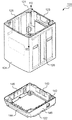
- FIG. 2 is a schematic exploded perspective view of the lower housing 120. As shown in FIG. The lower housing 120 is described with reference to FIGS. 1 and 2.
- the lower housing 120 includes a substantially rectangular cylindrical side wall portion 121 and a rectangular frame-like pedestal portion 122 for supporting the side wall portion 121.
- the side wall portion 121 fixed to the pedestal portion 122 is erected along the processing tank 200.
- the side wall portion 121 includes a back wall 123, a front wall 124 opposite to the back wall 123, a left wall 125 erected between the back wall 123 and the front wall 124, and an opposite side to the left wall 125. And the right wall 126.
- the back wall 123 is exemplified as a first wall.
- the front wall 124 is illustrated as a second wall.
- the left wall 125 is illustrated as a third wall.
- the right wall 126 is illustrated as a fourth wall.
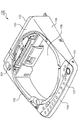
- FIG. 3 is a schematic perspective view of the upper housing 130.
- the upper housing 130 is described with reference to FIGS. 1 to 3.
- the upper housing 130 has a top wall 131 forming the upper surface of the washing machine 100, an upper back wall 133 substantially flush with the back wall 123 of the lower housing 120, and a front wall 124 of the lower housing 120
- the controller 150 is mounted along the back wall 123.
- the control device 150 controls various processes such as a washing process, a dewatering process, and a drying process of the washing machine 100.
- the operation panel 151 is attached along the front edge 137 of the ceiling wall 131. Operation panel 151 is electrically connected to control device 150. The user can operate the operation panel 151 to cause the washing machine 100 to perform a desired operation.
- the top wall 131 is formed with a substantially circular opening 138.
- the upper housing 130 further includes a lid 139 closing the opening 138.
- the lid 139 is attached to the top wall 131 so as to be vertically pivotable. The user can put the clothes into the processing tank 200 by rotating the lid 139 upward. Alternatively, the user can rotate the lid 139 upward and take out the clothes from the processing tank 200.
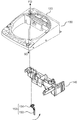
- FIG. 4 is a schematic exploded perspective view showing the various elements attached to the upper housing 130. The elements attached to the upper housing 130 will be described using FIGS. 1, 2 and 4.
- the washing machine 100 includes a mechanical switch element 152 used as a sensor element for detecting the vibration of the processing tank 200.
- the switch element 152 electrically connected to the control device 150 outputs a detection signal including information on the vibration of the processing tank 200.
- the control device 150 controls the processing tank 200 based on the detection signal from the switch element 152.
- the washing machine 100 further includes a support piece 140 for supporting the switch element 152.
- the support piece 140 is fixed along the upper back wall 133 of the upper housing 130.
- the switch element 152 attached to the left end of the support piece 140 protrudes downward and enters a corner between the rear wall 123 and the left wall 125 of the lower housing 120.
- Switch element 152 includes a lever portion 153 extending downward, and a signal generation portion 154 which generates and outputs a detection signal in accordance with the posture of lever portion 153. If the processing tank 200 is largely displaced toward the corner between the back wall 123 and the left wall 125, as shown in FIG. 4, the lever portion 153 is formed of the back wall 123 (and the upper back wall 133). Turn towards). At this time, the signal generation unit 154 generates and outputs a detection signal for stopping (or decelerating) the rotation of the processing tank 200.
- the direction toward the corner between the back wall 123 and the left wall 125 is referred to as a first direction FD. Further, the direction opposite to the first direction FD is referred to as a second direction SD.
- the switch element 152 is exemplified as the first sensor element.
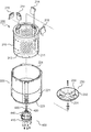
- FIG. 5 is a schematic exploded perspective view of the processing tank 200.
- the processing tank 200 is described with reference to FIGS. 1 to 3 and 5.
- the processing tank 200 includes an inner tank 210 that rotates to dewater the clothes, and an outer tank 220 that accommodates the inner tank 210.
- the user can open the lid 139 of the upper housing 130 and store the clothes in the inner tub 210.
- the inner tank 210 includes a substantially cylindrical peripheral wall 211 and a bottom wall 212 connected to the lower end of the peripheral wall 211.
- a large number of through holes 213 are formed in the peripheral wall 211.
- the water dewatered from the clothes is discharged from the inner tank 210 through the through holes 213.
- the outer tank 220 receives the water discharged from the through hole 213.
- the outer tank 220 includes a substantially cylindrical peripheral wall 221 and a bottom wall 222 connected to the peripheral wall 221.
- the peripheral wall 221 includes a lower edge 223 to which the bottom wall 222 is attached, and an upper edge 224 opposite to the lower edge 223.
- the lower edge 223 is exemplified as the first edge.
- the upper edge 224 is illustrated as a second edge.
- an opening 225 is formed in the bottom wall 222. Water dewatered from the garment is drained from the outer tub 220 through the opening 225.
- the washing machine 100 further includes a connection duct 226 connected to the opening 225, and a drainage system 300 for discharging water out of the housing 110.
- the pedestal portion 122 includes a lower back wall 143 substantially flush with the back wall 123 of the side wall portion 121, and a lower front wall 144 substantially flush with the front wall 124 of the side wall portion 121.
- a lower left wall 145 substantially flush with the left wall 125 of the side wall portion 121 and a lower right wall 146 substantially flush with the right wall 126 of the side wall portion 121 are included.
- a drain port 142 is formed in the lower back wall 143.
- the drainage system 300 controls the control pipe 150 and the drainage pipe 310 including the first end 311 connected to the connection duct 226 and the second end 312 connected to the drainage port 142. And a drain valve 320 for opening and closing the drain pipe 310 below.
- the drain valve 320 opens the drain pipe 310, the water in the outer tank 220 is drained out of the housing 110 through the drain pipe 310.
- the processing tank 200 includes a pulsator 230 substantially in the shape of a round dish.
- the pulsator 230 includes a disc portion 231 lying on the bottom wall 212 of the inner tank 210, and an inclined ring 232 projecting upward from the periphery of the disc portion 231.
- the inclined ring 232 spreads upward.
- the pulsator 230 further includes a stirring rib 233 protruding from the upper surface of the disc portion 231 and the inclination ring 232.
- the stirring ribs 233 extend radially.
- the pulsator 230 rotates while washing the clothes and / or drying the clothes. Thus, in these steps, the clothes are properly agitated.
- the washing machine 100 further includes a drive mechanism 400 that selectively rotates the inner tub 210 and the pulsator 230 under the control of the controller 150.
- the drive mechanism 400 includes a drive motor 410 generating a driving force for rotating the inner tank 210 or the pulsator 230, a first shaft 420 connected to the inner tank 210, and a second shaft 430 connected to the pulsator 230; And a clutch device for switching transmission of driving force of the motor between the first shaft and the second shaft.
- the drive motor 410 and the clutch device 440 operating under the control of the controller 150 are fixed to the bottom wall 222 of the outer tub 220.
- the first shaft 420 penetrates the bottom wall 222 of the outer tub 220 and is connected to the bottom wall 212 of the inner tub 210.
- the second shaft 430 which rotates concentrically with the first shaft 420, protrudes from the first shaft 420 and is connected to the pulsator 230 in the inner tank 210.
- the drive motor 410 is exemplified as a drive source.
- the clutch device 440 switches the transmission path of the driving force so that the driving force is transmitted to the second shaft 430.
- the pulsator 230 rotates in the inner tank 210.
- the washing machine 100 further includes a water supply system 500 for supplying water used to wash clothes to the treatment tank 200.
- the water supply system 500 includes a water supply unit 510 attached to a water supply port 501 (see FIG. 3) formed in the top wall 131 of the upper housing 130, and a switching valve 520 for switching the path of water supplied from the water supply unit 510. And a water supply pipe 530 defining a water path from the switching valve 520 to the outer tank 220.
- the water supply unit 510 is connected to, for example, a water tap (not shown).
- a water tap not shown.
- the processing tank 200 includes a collection bag 214 for capturing and collecting lint separated from clothes being laundered, and a fluid balancer 215 that acts to keep the inner tank 210 balanced.
- the collection bag 214 and the fluid balancer 215 are attached to the upper edge of the inner tank 210.
- the outer tub 220 is connected to the upper edge 224 of the peripheral wall 221, and is an upper plate 227 lying on the inner tub 210, and an inner lid pivotally attached to the upper plate 227 so as to be vertically movable. And 229.
- the user can load the clothes into the inner tub 210 by rotating the inner lid 229 below the lid 139 of the upper housing 130 upward. Alternatively, the user can take out the clothes from the inner tub 210.
- a sealing structure is formed between the upper plate 227 and the inner lid 229. Thus, little or no water in the treatment tank 200 leaks from the opening of the upper plate 227.
- the washing machine 100 further comprises a circulation system 600 for circulating dry air for drying the clothes.
- the circulation system 600 includes a tubular heat exchanger 610 connected to the connection duct 226, and a guide pipe 611 for guiding water from the switching valve 520 to the heat exchanger 610.
- the switching valve 520 opens the water channel to the guide pipe 611, water is supplied to the heat exchanger 610.
- the heat exchanger 610 includes a lower end 612 connected to the connection duct 226 and an upper end 613 connected to the guide pipe 611.
- the dry air flowing upward exchanges heat with the water flowing in from the upper end 613 of the heat exchanger 610. As a result, the dry air is properly dehumidified.
- Circulation system 600 further comprises a cooling fan 620 attached to back wall 123.
- the cooling fan 620 blows toward the heat exchanger 610 to cool the dry air. As a result, dehumidification of dry air is promoted.
- the circulation system 600 includes a blower fan 630 for sending dehumidified dry air to the treatment tank 200, a heater 640 for heating the dry air between the blower fan 630 and the treatment tank 200, and the heated dry air for the treatment tank 200. And an introduction pipe 650 for guiding the user.
- the introduction pipe 650 is connected to the upper plate 227.
- the circulation system 600 can supply the dry air to the processing tank 200 through the introduction pipe 650 and can collect the dry air through the connection duct 226. Thus, the circulation of dry air around the treatment vessel 200 is achieved.
- the washing machine 100 further includes a suspension element 240 that connects the housing 110 and the outer tub 220.
- the suspension element 240 supporting the outer tub 220 dampens the vibrations transmitted from the outer tub 220 to the housing 110.
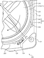
- FIG. 6 is a schematic enlarged plan view around the corner between the front wall 124 and the right wall 126.
- the washing machine 100 is further described using FIGS. 1, 2, 4 and 6.
- the pulsator 230, the inner tank 210 and the outer tank 220 are disposed substantially concentrically.
- relatively heavy clothing containing water collides with the peripheral wall 211 of the inner tank 210.
- the clothing is potentially uneventated in the inner tub 210.
- the collision and / or uneven distribution of the clothes cause the treatment tank 200 to vibrate.
- the peripheral wall 221 of the outer tub 220 includes an inner surface 241 opposite to the peripheral wall 211 of the inner tub 210 and an outer surface 242 opposite to the inner surface 241.
- the outer surface 242 faces the side wall portion 121. As shown in FIG. 6, the outer surface 242 is close to the sidewall 121.
- Washing machine 100 further includes an acceleration sensor 700.
- the acceleration sensor 700 attached to the outer surface 242 of the peripheral wall 221 detects the acceleration of the outer surface 242 as information on the vibration of the dewatering tank. Further, acceleration sensor 700 outputs a detection signal corresponding to the acceleration of outer surface 242 to control device 150.
- the acceleration sensor 700 is used as a sensor element together with the switch element 152 described with reference to FIG. Moreover, the acceleration sensor 700 is illustrated as a 2nd sensor element.
- the acceleration sensor 700 preferably detects at least one of an acceleration component in the radial direction of the outer tub 220 and an acceleration component in the circumferential direction of the outer tub 220. As a result, the vibration of the outer tub 220 is properly measured. More preferably, in addition to the acceleration component in the radial direction of the outer tank 220 and the acceleration component in the circumferential direction of the outer tank 220, the acceleration sensor 700 is vertically (i.e., radial direction of the outer tank 220 and circumferential direction of the outer tank 220). The acceleration component in the direction orthogonal to (1) may be detected. As a result, the control device 150 can appropriately analyze the vibration pattern of the outer tub 220 based on the detection signal from the acceleration sensor 700.
- the acceleration sensor 700 is disposed at a corner surrounded by the outer tank 220, the front wall 124 and the right wall 126. Since the space formed between the substantially cylindrical outer tank 220 and the substantially rectangular cylindrical sidewall portion 121 is suitably used for the arrangement of the acceleration sensor 700, an additional space for the arrangement of the acceleration sensor 700 is provided. Space is not required. Thus, a small washing machine 100 is provided.
- the switch element 152 is disposed at the corner between the back wall 123 and the left wall 125.
- acceleration sensor 700 is disposed between front wall 124 and right wall 126. Therefore, acceleration sensor 700 is arranged diagonally of housing 110 with respect to switch element 152 (that is, with respect to switch element 152 in the second direction SD).
- the vibration of the processing tank 200 due to the uneven distribution and / or the collision of the clothes between the right wall 126 and the back wall 123 is an acceleration sensor 700. Is detected by The vibration of the processing tank 200 due to the uneven distribution and / or collision of the clothes between the left wall 125 and the front wall 124 is detected by the switch element 152. Therefore, within a period in which the processing tank 200 makes a half rotation, the vibration of the processing tank 200 is detected by at least one of the acceleration sensor 700 and the switch element 152. Thus, the vibration of the processing tank 200 is quickly detected.
- the control device 150 analyzes the vibration mode of the processing tank 200 based on detection signals output from the switch element 152 and the acceleration sensor 700. If the amplitude of the processing tank 200 exceeds a predetermined threshold for the amplitude, the controller 150 reduces the number of rotations of the drive motor 410. Alternatively, the control device 150 stops the drive motor 410. Thus, the momentum of the processing tank 200 is reduced, and the amplitude of the processing tank 200 is reduced.
- the outer surface 242 of the outer tub 220 is in close proximity to the side wall portion 121.
- the vibration of the processing tank 200 is rapidly detected by the acceleration sensor 700 and the switch element 152, the outer tank 220 and the side wall 121 are narrow even if the space between the outer surface 242 and the sidewall 121 is narrow. The collision with the side wall portion 121 is avoided or reduced. Thus, a small washing machine 100 is provided.
- the acceleration sensor 700 is preferably mounted near the upper edge 224 of the outer tub 220.
- An operator who intends to adjust or repair the acceleration sensor 700 can easily access the acceleration sensor 700 attached near the upper edge 224 of the outer tub 220 after separating the upper housing 130 from the lower housing 120. Can. Therefore, maintenance, attachment or removal of acceleration sensor 700 can be easily performed.
- the acceleration sensor 700 attached near the upper edge 224 of the outer tank 220 can properly detect the acceleration of the outer tank 220. .
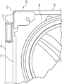
- FIG. 7 is a schematic perspective view of the heat exchanger 610 attached to the housing 110.
- FIG. 8 is a schematic enlarged plan view around the corner between the right wall 126 and the back wall 123. The attachment of the heat exchanger 610 is described with reference to FIGS. 1, 7 and 8.
- the housing 110 further includes a back cover plate 129 attached to the back wall 123.
- the heat exchanger 610 is erected between the back cover plate 129 and the back wall 123. As shown in FIG. 8, the heat exchanger 610 is disposed near the right wall 126. Therefore, the circulation system 600 described with reference to FIG. 1 is eccentrically disposed closer to the right wall 126 with respect to the rotation center of the processing tank 200.
- the circulation system 600 is connected to the upper surface (i.e., the upper plate 227) and the lower surface (i.e., the bottom wall 222 of the outer tank 220) of the processing tank 200 near the right wall 126. Also, the heat exchanger 610 extends upward along the back wall 123 and the back cover plate 129. Therefore, circulation system 600 suppresses the displacement of processing tank 200 in the vertical direction centering on the region near the corner between right wall 126 and back wall 123. In the present embodiment, the circulation system 600 is illustrated as a suppression element.
- the processing tank 200 moves up and down relatively. It's easy to do. For example, when the user drains water on the top plate 227, the water therefore flows towards the corner between the left wall 125 and the front wall 124.
- there is no sensor element such as the acceleration sensor 700 or the switch element 152 at the corner between the left wall 125 and the front wall 124. Sensor elements such as 700 and switch element 152 hardly fail. Thus, a reliable washing machine 100 is provided.
- the embodiments described above mainly include the following configurations.
- a dehydrating apparatus includes a dewatering tank that rotates to dewater clothes, a sensor element that outputs a detection signal including information on vibration of the dewatering tank, and the detection signal.
- a second sensor element disposed in a second direction opposite to the second sensor element.
- the sensor element outputs a detection signal including information on the vibration of the dewatering tank that rotates to dewater the clothes.
- the controller controls the dehydration tank based on the detection signal.
- the first sensor element of the sensor element detects the amplitude of the dewatering tank in the first direction.
- the second sensor element of the sensor element is arranged with respect to the first sensor element in a second direction opposite to the first direction. Therefore, in the rotation operation of the dewatering tank, the vibration of the dewatering tank generated in the half-turn section is detected by one of the first sensor element and the second sensor element.
- the vibration of the dewatering tank generated in the other half cycle is detected by the other of the first sensor element and the second sensor element. Therefore, the vibration of the dewatering tank is immediately detected.
- the apparatus further includes a housing that accommodates the dewatering tank, and the housing includes a first wall erected along the dewatering tank, and a second wall opposite to the first wall.
- the second sensor element is disposed in a space surrounded by the second wall, the fourth wall, and the dehydration tank in a direction toward a corner formed between the third wall and the second wall. Is preferred.
- the housing for accommodating the dewatering tank includes the first wall erected along the dewatering tank, the second wall opposite to the first wall, the first wall, and the second wall, and And a fourth wall opposite to the third wall.
- the first sensor element detects an amplitude in a direction toward a corner formed between the first wall and the third wall.
- the second sensor element is disposed in a space surrounded by the second wall, the fourth wall, and the dewatering tank. Since the first sensor element and the second sensor element do not require a special space and are properly arranged, a compact drying device is provided.
- the dewatering tank includes an inner tank rotating to dewater the clothes, and an outer tank containing the inner tank, and the outer tank is a cylinder having an outer surface facing the housing.
- the second sensor element is attached to the outer surface.
- the dewatering tank includes an outer tank that accommodates an inner tank that rotates to dewater the clothes.
- the outer tub includes a cylindrical peripheral wall having an outer surface facing the housing. Since the second sensor element is attached to the outer surface, it is properly disposed in the space surrounded by the second wall, the fourth wall and the dewatering tank. Since the second sensor element does not require a special space and is properly arranged, a compact drying device is provided.
- the first sensor element includes a mechanical switch element including a lever portion that changes the posture according to the amplitude of the dehydration tank
- the second sensor element is an acceleration sensor that detects an acceleration of the outer surface.
- the control device adjusts the rotation of the inner tank according to at least one of the posture of the lever portion and the acceleration.
- the first sensor element includes the mechanical switch element provided with the lever portion that changes the posture according to the amplitude of the dehydration tank.
- the second sensor element includes an acceleration sensor that detects an acceleration on the outer surface.
- the control device adjusts the rotation of the inner tank in accordance with at least one of the posture and the acceleration of the lever portion. Since different types of sensor elements are used to detect the vibration of the dewatering tank, the rotation of the inner tank is properly adjusted in response to various vibration patterns.
- the apparatus further comprises a drive source for rotating the inner tank
- the outer tank includes a bottom wall to which the drive source is attached, and the circumferential wall is a first edge to which the bottom wall is connected;
- the acceleration sensor includes a second edge opposite to the first edge, and the acceleration sensor be attached in the vicinity of the second edge.
- the outer tub includes a bottom wall to which a drive source for rotating the inner tub is attached.
- the second edge opposite to the first edge to which the bottom wall is connected vibrates with a relatively large amplitude.
- the acceleration sensor is attached near the second edge, so that the vibration of the outer bath can be properly detected.
- the suppressing element that suppresses the displacement of the dehydration tank, and the suppressing element is disposed eccentrically on the fourth wall side with respect to the rotation center of the inner tank.
- the suppressing element for suppressing the downward displacement of the dewatering tank is disposed eccentrically on the fourth wall side with respect to the rotation center of the inner tank. It becomes difficult to incline it. Therefore, the acceleration sensor is less likely to be exposed to water.
- the suppression element circulates the dry air around the dewatering tank so as to send the dry air for drying the clothes to the dewatering tank and collect the dry air from the dewatering tank.
- a system is included.
- the suppression element includes a circulation system that circulates the dry air around the dehydration tank so as to send the dry air for drying the clothes to the dehydration tank and collect the dry air from the dehydration tank.
- the garment can be subjected to drying as well as dehydration.
- the acceleration sensor preferably detects at least one of an acceleration component in the radial direction of the outer tub and an acceleration component in the circumferential direction of the outer tub.
- the acceleration sensor detects at least one of the acceleration component in the radial direction of the outer tank and the acceleration component in the circumferential direction of the outer tank, the vibration of the dewatering tank is appropriately detected.
- the acceleration sensor detect an acceleration component in a direction orthogonal to an acceleration component in the radial direction of the outer tank and an acceleration component in the circumferential direction of the outer tank.
- the acceleration sensor detects the acceleration component in the radial direction of the outer tank and the acceleration component in the direction orthogonal to the acceleration component in the circumferential direction of the outer tank, corresponding to various vibration patterns, The dewatering tank is controlled.
Landscapes
- Engineering & Computer Science (AREA)
- Textile Engineering (AREA)
- Control Of Washing Machine And Dryer (AREA)
- Main Body Construction Of Washing Machines And Laundry Dryers (AREA)
Abstract
衣類を脱水する脱水槽(200)と、前記脱水槽(200)の振動に関する情報を含む検出信号を出力するセンサ要素(152、700)と、前記検出信号に基づき、前記脱水槽(200)を制御する制御装置(150)と、を含み、前記センサ要素は、前記脱水槽(200)の第1方向の振幅を検出する第1センサ素子(152)と、前記第1センサ素子(152)に対して、前記第1方向とは反対の第2方向に取り付けられた第2センサ素子(700)と、を含むことを特徴とする脱水装置。
Description
本発明は、衣類を脱水するための脱水装置に関する。
脱水装置は、典型的には、衣類を脱水するための脱水槽を備える。脱水槽は、一般的に、衣類を脱水するために回転する内槽と、内槽を収容する外槽を備える。内槽の周壁には、多数の透孔が形成される。衣類から脱水された水は、透孔を通じて、内槽から排出される。外槽は、内槽から出た水を受け止める。
脱水処理を受ける衣類は、水を含んでいるので、比較的重い。内槽の回転によって、衣類は、内槽の周壁に衝突する。この結果、脱水が促される。その一方で、衣類と内槽の周壁との衝突は、脱水槽の振動を引き起こす。
特許文献1乃至7は、脱水槽の大きな振幅を検出するスイッチ素子を開示する。脱水槽が大きく変位したとき、スイッチ素子が作動し、内槽の回転が停止される。
特許文献8及び9は、スイッチ素子の代わりに、加速度センサを用いて、脱水槽の振動を検出する洗濯機を開示する。特許文献8及び9の開示によれば、加速度センサは、スイッチ素子では検出が困難な高速回転時における脱水槽の振動も検出することができる。
脱水槽中の衣類の分布は、ランダムに変動する。したがって、衣類の分布によっては、上述の加速度センサやスイッチ素子では、振動を即座に検出できないこともある。
本発明は、脱水槽の振動を即座に検出することができる脱水装置を提供することを目的とする。
本発明の一局面に係る脱水装置は、衣類を脱水するように回転動作をする脱水槽と、該脱水槽の振動に関する情報を含む検出信号を出力するセンサ要素と、前記検出信号に基づき、前記脱水槽を制御する制御装置と、を含み、前記センサ要素は、前記脱水槽の第1方向の振幅を検出する第1センサ素子と、前記第1センサ素子に対して、前記第1方向とは反対の第2方向に配設された第2センサ素子と、を含むことを特徴とする。
本発明に係る脱水装置は、脱水槽の振動を即座に検出することができる。
以下、図面を参照しつつ、脱水装置の一実施形態が説明される。尚、以下の説明で用いられる「上」、「下」、「左」や「右」などの方向を表す用語は、単に、説明の明瞭化を目的とするものであり、脱水装置の原理を何ら限定するものではない。
図1は、本実施形態に従う脱水装置として例示される洗濯機の概略的な縦断面図である。図1を用いて、洗濯機が説明される。尚、図1に示される洗濯機は、衣類を洗濯するための洗濯機能だけでなく、衣類を乾燥するための乾燥機能を有する。脱水装置は、衣類を脱水する機能を有する様々な装置であり、洗濯機以外の装置であってもよい。
洗濯機100は、略矩形箱状の筐体110と、筐体110内に配設される処理槽200と、を備える。処理槽200は、洗濯処理、脱水処理や乾燥処理といった様々な処理を行う。本実施形態において、処理槽200は、衣類を脱水するための脱水槽として例示される。
筐体110は、略矩形箱状の下部筐体120と、下部筐体120上に固定される上部筐体130と、を備える。処理槽200は、主に、下部筐体120内に収容される。
図2は、下部筐体120の概略的な展開斜視図である。図1及び図2を用いて、下部筐体120が説明される。
下部筐体120は、略矩形筒状の側壁部121と、側壁部121を支持する矩形枠状の台座部122と、を備える。台座部122に固定された側壁部121は、処理槽200に沿って立設される。
側壁部121は、背面壁123と、背面壁123とは反対側の正面壁124と、背面壁123と正面壁124との間で立設する左壁125と、左壁125とは反対側の右壁126と、を含む。本実施形態において、背面壁123は、第1壁として例示される。正面壁124は、第2壁として例示される。左壁125は、第3壁として例示される。右壁126は、第4壁として例示される。
図3は、上部筐体130の概略的な斜視図である。図1乃至図3を用いて、上部筐体130が説明される。
上部筐体130は、洗濯機100の上面を形成する天壁131と、下部筐体120の背面壁123と略面一となる上背面壁133と、下部筐体120の正面壁124と略面一となる上正面壁134と、下部筐体120の左壁125と略面一となる上左壁135と、下部筐体120の右壁126と略面一となる上右壁136と、を含む。
図1に示される如く、背面壁123に沿って、制御装置150が取り付けられる。制御装置150は、洗濯機100の洗濯処理、脱水処理や乾燥処理といった様々な処理の制御を司る。
図3に示される如く、天壁131の正面縁137に沿って、操作パネル151が取り付けられる。操作パネル151は、制御装置150に電気的に接続される。使用者は、操作パネル151を操作し、洗濯機100に所望の動作をさせることができる。
図3に示される如く、天壁131には、略円形の開口部138が形成される。図1に示される如く、上部筐体130は、開口部138を閉塞する蓋体139を更に備える。蓋体139は、天壁131に対して、上下に回動可能に取り付けられる。使用者は、蓋体139を上方に回動させ、処理槽200へ衣類を投入することができる。或いは、使用者は、蓋体139を上方に回動させ、処理槽200から衣類を取り出すことができる。
図4は、上部筐体130に取り付けられる様々な要素を示す概略的な展開斜視図である。図1、図2及び図4を用いて、上部筐体130に取り付けられる要素が説明される。
洗濯機100は、処理槽200の振動を検出するセンサ要素として用いられる機械式のスイッチ素子152を備える。制御装置150に電気的に接続されたスイッチ素子152は、処理槽200の振動に関する情報を含む検出信号を出力する。制御装置150は、スイッチ素子152からの検出信号に基づいて、処理槽200を制御する。
洗濯機100は、スイッチ素子152を支持する支持片140を更に備える。支持片140は、上部筐体130の上背面壁133に沿って固定される。支持片140の左端に取り付けられたスイッチ素子152は、下方に突出し、下部筐体120の背面壁123及び左壁125との間の角隅部に侵入する。
スイッチ素子152は、下方に延出するレバー部153と、レバー部153の姿勢に応じて検出信号を生成及び出力する信号生成部154と、を含む。処理槽200が、背面壁123及び左壁125との間の角隅部に向けて大きく変位するならば、図4に示される如く、レバー部153は、背面壁123(及び、上背面壁133)に向けて回動する。このとき、信号生成部154は、処理槽200の回転を停止(或いは、減速)するための検出信号を生成及び出力する。以下の説明において、背面壁123及び左壁125との間の角隅部に向かう方向は、第1方向FDと称される。また、第1方向FDと反対の方向は、第2方向SDと称される。本実施形態において、スイッチ素子152は、第1センサ素子として例示される。
図5は、処理槽200の概略的な展開斜視図である。図1乃至図3並びに図5を用いて、処理槽200が説明される。
処理槽200は、衣類を脱水するために回転する内槽210と、内槽210を収容する外槽220と、を備える。使用者は、上部筐体130の蓋体139を開け、衣類を内槽210に収容することができる。
内槽210は、略円筒形状の周壁211と、周壁211の下端に接続される底壁212と、を備える。周壁211には、多数の透孔213が形成される。衣類から脱水された水は、透孔213を通じて、内槽210から排出される。外槽220は、透孔213から排出された水を受ける。
外槽220は、略円筒形状の周壁221と、周壁221に接続される底壁222と、を備える。周壁221は、底壁222が取り付けられる下縁223と、下縁223とは反対側に上縁224と、を含む。本実施形態において、下縁223は、第1縁として例示される。また、上縁224は、第2縁として例示される。
図1に示される如く、底壁222には開口部225が形成される。衣類から脱水された水は、開口部225を通じて、外槽220から排出される。洗濯機100は、開口部225に接続される接続ダクト226と、筐体110外へ水を排出するための排水システム300と、を更に備える。
図2に示される如く、台座部122は、側壁部121の背面壁123に略面一となる下背面壁143と、側壁部121の正面壁124と略面一となる下正面壁144と、側壁部121の左壁125と略面一となる下左壁145と、側壁部121の右壁126と略面一となる下右壁146と、を含む。下背面壁143には、排水口142が形成される。
図1に示される如く、排水システム300は、接続ダクト226に接続される第1端部311と排水口142に接続される第2端部312とを含む排水管310と、制御装置150の制御下で排水管310を開閉する排水弁320と、を備える。排水弁320が排水管310を開くと、外槽220中の水が排水管310を通じて、筐体110外へ排出される。
図1及び図5に示されるように、処理槽200は、略丸皿状のパルセータ230を備える。パルセータ230は、内槽210の底壁212上で横たわる円板部231と、円板部231の周縁から上方に突出する傾斜リング232と、を含む。傾斜リング232は、上方に向けて拡がる。パルセータ230は、円板部231及び傾斜リング232の上面から突出する攪拌リブ233を更に備える。攪拌リブ233は、放射状に延びる。パルセータ230は、衣類を洗濯する間及び/又は衣類を乾燥する間、回転する。かくして、これらの工程において、衣類は適切に攪拌される。
洗濯機100は、制御装置150の制御下で、内槽210及びパルセータ230を選択的に回転する駆動機構400を更に備える。駆動機構400は、内槽210又はパルセータ230を回転させる駆動力を発生させる駆動モータ410と、内槽210に接続された第1シャフト420と、パルセータ230に接続される第2シャフト430と、駆動モータ410の駆動力の伝達を、第1シャフト420と第2シャフト430との間で切り替えるクラッチ装置440と、を備える。制御装置150の制御下で動作する駆動モータ410及びクラッチ装置440は、外槽220の底壁222に固定される。第1シャフト420は、外槽220の底壁222を貫き、内槽210の底壁212に接続される。第1シャフト420と同心回転する第2シャフト430は、第1シャフト420から突出し、内槽210内のパルセータ230に接続される。本実施形態において、駆動モータ410は、駆動源として例示される。
衣類を洗濯するための洗濯工程において、クラッチ装置440は、第2シャフト430へ駆動力が伝達されるように駆動力の伝達経路を切り替える。この結果、洗濯工程において、パルセータ230は、内槽210内で回転する。
図1に示される如く、洗濯機100は、衣類の洗濯に用いられる水を処理槽200へ供給するための給水システム500を更に備える。給水システム500は、上部筐体130の天壁131に形成された給水口501(図3参照)に取り付けられる給水部510と、給水部510から供給された水の経路を切り替える切替弁520と、切替弁520から外槽220への水の経路を規定する給水管530と、を備える。
給水部510は、例えば、水道の蛇口(図示せず)に接続される。切替弁520が給水管530への水路を開くと、水は、処理槽200へ供給される。
図5に示される如く、処理槽200は、洗濯中の衣類から分離したリントを捕捉並びに回収する回収袋214と、内槽210のバランスを保つように作用する流体バランサ215と、を含む。回収袋214及び流体バランサ215は、内槽210の上縁に取り付けられる。
図1に示される如く、外槽220は、周壁221の上縁224に接続され、内槽210上で横たわる上板227と、上板227に対して上下に回動可能に取り付けられた内蓋229と、を更に備える。使用者は、上部筐体130の蓋体139の下方の内蓋229を上方に回動させ、内槽210へ衣類を投入することができる。或いは、使用者は、内槽210から衣類を取り出すことができる。使用者が内蓋229を下方に回動させると、上板227と内蓋229との間でシール構造が形成される。かくして、処理槽200内の水が上板227の開口部からほとんど或いは全く漏出しない。
洗濯機100は、衣類を乾燥するための乾燥空気を循環する循環システム600を更に備える。循環システム600は、接続ダクト226に接続された管型の熱交換器610と、切替弁520から熱交換器610へ水を案内する案内管611と、を備える。切替弁520が案内管611への水路を開くと、水は熱交換器610へ供給される。
熱交換器610は、接続ダクト226に接続される下端部612と、案内管611に接続される上端部613と、を含む。上方に向けて流れる乾燥空気は、熱交換器610の上端部613から流入した水と熱交換する。この結果、乾燥空気は、適切に除湿される。
循環システム600は、背面壁123に取り付けられた冷却ファン620を更に備える。冷却ファン620は、熱交換器610に向けて送風し、乾燥空気を冷却する。この結果、乾燥空気の除湿が促進される。
循環システム600は、除湿された乾燥空気を処理槽200へ送り込む送風ファン630と、送風ファン630と処理槽200との間で乾燥空気を加熱するヒータ640と、加熱された乾燥空気を処理槽200へ案内する導入管650と、を更に備える。導入管650は、上板227に接続される。循環システム600は、導入管650を通じて、処理槽200へ乾燥空気を送り込むとともに接続ダクト226を通じて乾燥空気を回収することができる。かくして、処理槽200の周りでの乾燥空気の循環が達成される。
洗濯機100は、筐体110と外槽220とを接続するサスペンション要素240を更に備える。外槽220を支持するサスペンション要素240は、外槽220から筐体110へ伝達される振動を減衰させる。
図6は、正面壁124と右壁126との間の角隅部の周りの概略的な拡大平面図である。図1、図2、図4及び図6を用いて、洗濯機100が更に説明される。
パルセータ230、内槽210及び外槽220は、略同心に配設される。脱水工程において、水を含んだ比較的重い衣類は、内槽210の周壁211に衝突する。或いは、衣類は、内槽210内で潜在的に偏在する。衣類の衝突及び/又は偏在は、処理槽200の振動を引き起こす。
外槽220の周壁221は、内槽210の周壁211に対向する内面241と、内面241とは反対側の外面242と、を含む。外面242は、側壁部121に対向する。図6に示される如く、外面242は、側壁部121に近接している。
洗濯機100は、加速度センサ700を更に備える。周壁221の外面242に取り付けられた加速度センサ700は、脱水槽の振動に関する情報として、外面242の加速度を検出する。また、加速度センサ700は、外面242の加速度に応じた検出信号を制御装置150へ出力する。本実施形態において、加速度センサ700は、図4に関連して説明されたスイッチ素子152とともにセンサ要素として用いられる。また、加速度センサ700は、第2センサ素子として例示される。
加速度センサ700は、好ましくは、外槽220の半径方向の加速度成分及び外槽220の周方向の加速度成分のうち少なくとも一方を検出する。この結果、外槽220の振動は、適切に測定される。更に好ましくは、加速度センサ700は、外槽220の半径方向の加速度成分及び外槽220の周方向の加速度成分に加えて、上下方向(即ち、外槽220の半径方向及び外槽220の周方向に対して直交する方向)の加速度成分を検出してもよい。この結果、制御装置150は、加速度センサ700からの検出信号に基づいて、外槽220の振動パターンを適切に解析することができる。
加速度センサ700は、外槽220と正面壁124と右壁126とに囲まれる角隅部に配設される。略円筒状の外槽220と略矩形筒状の側壁部121との間に形成される空間は、加速度センサ700の配置に好適に利用されるので、加速度センサ700の配置のための追加的な空間の確保は必要とされない。かくして、小型の洗濯機100が提供される。
図4に関連して説明された如く、スイッチ素子152は、背面壁123と左壁125との間の角隅部に配設される。一方、加速度センサ700は、正面壁124と右壁126との間に配設される。したがって、加速度センサ700は、スイッチ素子152に対して、筐体110の対角線上に(即ち、スイッチ素子152に対して、第2方向SDに)配設される。
図6に示される如く、処理槽200が時計回りに回転するならば、右壁126と背面壁123との間における衣類の偏在及び/又は衝突に起因する処理槽200の振動は、加速度センサ700によって検出される。左壁125と正面壁124との間における衣類の偏在及び/又は衝突に起因する処理槽200の振動は、スイッチ素子152によって検出される。したがって、処理槽200が半回転する期間以内で、処理槽200の振動は加速度センサ700及びスイッチ素子152のうち少なくとも一方によって検出されることとなる。かくして、処理槽200の振動は、迅速に検出される。
制御装置150は、スイッチ素子152及び加速度センサ700から出力された検出信号に基づき、処理槽200の振動モードを解析する。処理槽200の振幅が、振幅に対して定められた閾値を超えるならば、制御装置150は、駆動モータ410の回転数を低減させる。或いは、制御装置150は、駆動モータ410を停止させる。かくして、処理槽200の運動量が低減され、処理槽200の振幅が小さくなる。
図6に示される如く、外槽220の外面242は、側壁部121に近接している。上述の如く、加速度センサ700及びスイッチ素子152によって、処理槽200の振動は、迅速に検出されるので、外槽220の外面242と側壁部121との間の空間が狭くとも、外槽220と側壁部121との衝突は回避或いは低減される。したがって、小型の洗濯機100が提供される。
加速度センサ700は、好ましくは、外槽220の上縁224の近傍に取り付けられる。加速度センサ700を調整或いは修繕しようとする作業者は、上部筐体130を下部筐体120から分離した後、外槽220の上縁224の近傍に取り付けられた加速度センサ700に容易にアクセスすることができる。したがって、加速度センサ700のメンテナンス、取付或いは除去が容易に行われる。加えて、外槽220の上縁224の振幅は、比較的大きいので、外槽220の上縁224の近傍に取り付けられた加速度センサ700は、外槽220の加速度を適切に検出することができる。
図7は、筐体110に取り付けられる熱交換器610の概略的な斜視図である。図8は、右壁126と背面壁123との間の角隅部の周りの概略的な拡大平面図である。図1、図7及び図8を用いて、熱交換器610の取付が説明される。
筐体110は、背面壁123に取り付けられる背面カバー板129を更に含む。背面カバー板129と背面壁123との間で、熱交換器610は立設される。図8に示される如く、熱交換器610は、右壁126の近傍に配設される。したがって、図1に関連して説明された循環システム600は、処理槽200の回転中心に対して、右壁126寄りに偏心して配設される。
循環システム600は、右壁126の近くで、処理槽200の上面(即ち、上板227)及び下面(即ち、外槽220の底壁222)と接続される。また、熱交換器610は、背面壁123及び背面カバー板129に沿って上方に延びる。したがって、循環システム600は、右壁126と背面壁123との間の角隅部の近傍領域を中心に、処理槽200の上下方向への変位を抑制する。本実施形態において、循環システム600は、抑制要素として例示される。
一方、右壁126と背面壁123との間の角隅部と対角線上に存する左壁125と正面壁124との間の角隅部の近傍領域において、処理槽200は、比較的、上下動しやすい。例えば、使用者が上板227上に水を零したとき、それ故、水は、左壁125と正面壁124との間の角隅部に向けて流れる。本実施形態において、左壁125と正面壁124との間の角隅部には、加速度センサ700やスイッチ素子152といったセンサ要素は存在しないので、上板227上で零された水によって、加速度センサ700やスイッチ素子152といったセンサ要素が故障することはほとんどない。かくして、信頼性の高い洗濯機100が提供される。
上述の実施形態に関連して、脱水装置の原理が説明されている。上述された脱水装置の構成は、例示的なものにすぎない。したがって、上述の実施形態の原理を逸脱しない範囲で、脱水装置に対して様々な変更がなされてもよい。
上述された実施形態は、以下の構成を主に備える。
上述の実施形態の一局面に係る脱水装置は、衣類を脱水するように回転動作をする脱水槽と、該脱水槽の振動に関する情報を含む検出信号を出力するセンサ要素と、前記検出信号に基づき、前記脱水槽を制御する制御装置と、を含み、前記センサ要素は、前記脱水槽の第1方向の振幅を検出する第1センサ素子と、前記第1センサ素子に対して、前記第1方向とは反対の第2方向に配設された第2センサ素子と、を含むことを特徴とする。
上記構成によれば、センサ要素は、衣類を脱水するように回転動作をする脱水槽の振動に関する情報を含む検出信号を出力する。制御装置は、検出信号に基づき、脱水槽を制御する。センサ要素の第1センサ素子は、脱水槽の第1方向の振幅を検出する。センサ要素の第2センサ素子は、第1センサ素子に対して、第1方向とは反対の第2方向に配設される。したがって、脱水槽の回転動作において、半周分の区間において発生した脱水槽の振動は、第1センサ素子及び第2センサ素子のうち一方によって検出される。他の半周分の区間において発生した脱水槽の振動は、第1センサ素子及び第2センサ素子のうち他方によって検出される。したがって、脱水槽の振動が即座に検出されることとなる。
上記構成において、前記脱水槽を収容する筐体を更に備え、該筐体は、前記脱水槽に沿って立設される第1壁と、該第1壁とは反対側の第2壁と、前記第1壁と前記第2壁との間で立設される第3壁と、該第3壁とは反対側の第4壁と、を含み、前記第1方向は、前記第1壁と前記第3壁との間に形成された角隅部に向かう方向であり、前記第2センサ素子は、前記第2壁と前記第4壁と前記脱水槽とに囲まれる空間に配設されることが好ましい。
上記構成によれば、脱水槽を収容する筐体は、脱水槽に沿って立設される第1壁と、第1壁とは反対側の第2壁と、第1壁と第2壁との間で立設される第3壁と、第3壁とは反対側の第4壁と、を含む。第1センサ素子は、第1壁と第3壁との間に形成された角隅部に向かう方向の振幅を検出する。第2センサ素子は、第2壁と第4壁と脱水槽とに囲まれる空間に配設される。第1センサ素子及び第2センサ素子は、特別に設けられた空間を要せず、適切に配置されるので、小型の乾燥装置が提供される。
上記構成において、前記脱水槽は、前記衣類を脱水するために回転する内槽と、該内槽を収容する外槽と、を含み、該外槽は、前記筐体に対向する外面を有する円筒状の周壁を含み、前記第2センサ素子は、前記外面に取り付けられることが好ましい。
上記構成によれば、脱水槽は、衣類を脱水するために回転する内槽を収容する外槽と、を含む。外槽は、筐体に対向する外面を有する円筒状の周壁を含む。第2センサ素子は、外面に取り付けられるので、第2壁と第4壁と脱水槽とに囲まれる空間に適切に配設される。第2センサ素子は、特別に設けられた空間を要せず、適切に配置されるので、小型の乾燥装置が提供される。
上記構成において、前記第1センサ素子は、前記脱水槽の振幅に応じて、姿勢を変えるレバー部を備える機械式スイッチ素子を含み、前記第2センサ素子は、前記外面の加速度を検出する加速度センサを含み、前記制御装置は、前記レバー部の姿勢及び前記加速度のうち少なくとも一方に応じて、前記内槽の回転を調整することが好ましい。
上記構成によれば、第1センサ素子は、脱水槽の振幅に応じて、姿勢を変えるレバー部を備える機械式スイッチ素子を含む。第2センサ素子は、外面の加速度を検出する加速度センサを含む。制御装置は、レバー部の姿勢及び加速度のうち少なくとも一方に応じて、内槽の回転を調整する。異なる種類のセンサ素子が脱水槽の振動の検出に用いられるので、様々な振動パターンに対応して、内槽の回転が適切に調整される。
上記構成において、前記内槽を回転させるための駆動源を更に備え、前記外槽は、前記駆動源が取り付けられる底壁を含み、前記周壁は、前記底壁が接続される第1縁と、該第1縁とは反対側の第2縁とを含み、前記加速度センサは、前記第2縁の近傍に取り付けられることが好ましい。
上記構成によれば、外槽は、内槽を回転させるための駆動源が取り付けられる底壁を含む。底壁が接続される第1縁とは反対側の第2縁は、比較的大きな振幅で振動する。加速度センサは、第2縁の近傍に取り付けられるので、外槽の振動を適切に検出することができる。
上記構成において、前記脱水槽の変位を抑制する抑制要素を更に備え、前記抑制要素は、前記内槽の回転中心に対して、前記第4壁側に偏心して配設されることが好ましい。
上記構成によれば、脱水槽の下方への変位を抑制する抑制要素は、内槽の回転中心に対して、第4壁側に偏心して配設されるので、脱水槽は、第4壁に向けて傾斜しにくくなる。したがって、加速度センサは水に曝されにくくなる。
上記構成において、前記抑制要素は、前記衣類を乾燥するための乾燥空気を前記脱水槽に送り込むとともに該脱水槽から前記乾燥空気を回収するように前記脱水槽の周りで前記乾燥空気を循環させる循環システムを含むことが好ましい。
上記構成によれば、抑制要素は、衣類を乾燥するための乾燥空気を脱水槽に送り込むとともに脱水槽から乾燥空気を回収するように脱水槽の周りで乾燥空気を循環させる循環システムを含む。したがって、衣類は、脱水処理だけでなく乾燥処理も受けることができる。
上記構成において、前記加速度センサは、前記外槽の半径方向の加速度成分及び前記外槽の周方向の加速度成分のうち少なくとも一方を検出することが好ましい。
上記構成によれば、加速度センサは、外槽の半径方向の加速度成分及び外槽の周方向の加速度成分のうち少なくとも一方を検出するので、脱水槽の振動が適切に検出される。
上記構成において、前記加速度センサは、前記外槽の半径方向の加速度成分及び前記外槽の周方向の加速度成分に対して直交する方向の加速度成分を検出することが好ましい。
上記構成によれば、加速度センサは、外槽の半径方向の加速度成分及び外槽の周方向の加速度成分に対して直交する方向の加速度成分を検出するので、様々な振動パターンに対応して、脱水槽が制御される。
上述の実施形態の原理は、衣類を脱水させるための装置に好適に利用される。
Claims (9)
- 衣類を脱水する脱水槽と、
該脱水槽の振動に関する情報を含む検出信号を出力するセンサ要素と、
前記検出信号に基づき、前記脱水槽を制御する制御装置と、を含み、
前記センサ要素は、前記脱水槽の第1方向の振幅を検出する第1センサ素子と、前記第1センサ素子に対して、前記第1方向とは反対の第2方向に配設された第2センサ素子と、を含むことを特徴とする脱水装置。 - 前記脱水槽を収容する筐体を更に備え、
該筐体は、前記脱水槽に沿って立設される第1壁と、該第1壁とは反対側の第2壁と、前記第1壁と前記第2壁との間で立設される第3壁と、該第3壁とは反対側の第4壁と、を含み、
前記第1方向は、前記第1壁と前記第3壁との間に形成された角隅部に向かう方向であり、
前記第2センサ素子は、前記第2壁と前記第4壁と前記脱水槽とに囲まれる空間に配設されることを特徴とする請求項1に記載の脱水装置。 - 前記脱水槽は、前記衣類を脱水するために回転する内槽と、該内槽を収容する外槽と、を含み、
該外槽は、前記筐体に対向する外面を有する円筒状の周壁を含み、
前記第2センサ素子は、前記外面に取り付けられることを特徴とする請求項2に記載の脱水装置。 - 前記第1センサ素子は、前記脱水槽の振幅に応じて、姿勢を変えるレバー部を備える機械式スイッチ素子を含み、
前記第2センサ素子は、前記外面の加速度を検出する加速度センサを含み、
前記制御装置は、前記レバー部の姿勢及び前記加速度のうち少なくとも一方に応じて、前記内槽の回転を調整することを特徴とする請求項3に記載の脱水装置。 - 前記内槽を回転させるための駆動源を更に備え、
前記外槽は、前記駆動源が取り付けられる底壁を含み、
前記周壁は、前記底壁が接続される第1縁と、該第1縁とは反対側の第2縁とを含み、
前記加速度センサは、前記第2縁の近傍に取り付けられることを特徴とする請求項4に記載の脱水装置。 - 前記脱水槽の下方への変位を抑制する抑制要素を更に備え、
前記抑制要素は、前記内槽の回転中心に対して、前記第4壁側に偏心して配設されることを特徴とする請求項5に記載の脱水装置。 - 前記抑制要素は、前記衣類を乾燥するための乾燥空気を前記脱水槽に送り込むとともに該脱水槽から前記乾燥空気を回収するように前記脱水槽の周りで前記乾燥空気を循環させる循環システムを含むことを特徴とする請求項6に記載の脱水装置。
- 前記加速度センサは、前記外槽の半径方向の加速度成分及び前記外槽の周方向の加速度成分のうち少なくとも一方を検出することを特徴とする請求項4乃至7のいずれか1項に記載の脱水装置。
- 前記加速度センサは、前記外槽の半径方向の加速度成分及び前記外槽の周方向の加速度成分に対して直交する方向の加速度成分を検出することを特徴とする請求項8に記載の脱水装置。
Priority Applications (1)
| Application Number | Priority Date | Filing Date | Title |
|---|---|---|---|
| CN201280002534.7A CN103080403B (zh) | 2011-03-30 | 2012-02-17 | 脱水装置 |
Applications Claiming Priority (2)
| Application Number | Priority Date | Filing Date | Title |
|---|---|---|---|
| JP2011-073846 | 2011-03-30 | ||
| JP2011073846A JP2012205778A (ja) | 2011-03-30 | 2011-03-30 | 脱水装置 |
Publications (1)
| Publication Number | Publication Date |
|---|---|
| WO2012132200A1 true WO2012132200A1 (ja) | 2012-10-04 |
Family
ID=46929996
Family Applications (1)
| Application Number | Title | Priority Date | Filing Date |
|---|---|---|---|
| PCT/JP2012/001054 WO2012132200A1 (ja) | 2011-03-30 | 2012-02-17 | 脱水装置 |
Country Status (4)
| Country | Link |
|---|---|
| JP (1) | JP2012205778A (ja) |
| CN (1) | CN103080403B (ja) |
| TW (1) | TWI470129B (ja) |
| WO (1) | WO2012132200A1 (ja) |
Families Citing this family (2)
| Publication number | Priority date | Publication date | Assignee | Title |
|---|---|---|---|---|
| JP5773802B2 (ja) * | 2011-08-22 | 2015-09-02 | 株式会社東芝 | 洗濯機 |
| CN108486825B (zh) * | 2018-04-23 | 2020-11-10 | 海信(山东)冰箱有限公司 | 洗衣机控制方法和装置 |
Citations (4)
| Publication number | Priority date | Publication date | Assignee | Title |
|---|---|---|---|---|
| JPH06126079A (ja) * | 1992-10-20 | 1994-05-10 | Hitachi Ltd | 全自動洗濯機の運転方法 |
| JPH07178287A (ja) * | 1993-12-22 | 1995-07-18 | Matsushita Electric Ind Co Ltd | 洗濯機 |
| JPH10118388A (ja) * | 1996-10-22 | 1998-05-12 | Hitachi Ltd | 電気洗濯機 |
| JP2004344338A (ja) * | 2003-05-21 | 2004-12-09 | Hitachi Home & Life Solutions Inc | 洗濯機 |
Family Cites Families (7)
| Publication number | Priority date | Publication date | Assignee | Title |
|---|---|---|---|---|
| JPS6340228Y2 (ja) * | 1980-02-28 | 1988-10-20 | ||
| JP3178354B2 (ja) * | 1996-05-31 | 2001-06-18 | 株式会社日立製作所 | 洗濯機 |
| JP3258955B2 (ja) * | 1998-01-22 | 2002-02-18 | 三洋電機株式会社 | 全自動洗濯機 |
| DE10022609C2 (de) * | 2000-05-09 | 2003-11-13 | Whirlpool Co | Verfahren zur Begrenzung der Unwuchtwirkung einer Wascheinheit einer Waschmaschine und Vorrichtung zur Durchführung des Verfahrens |
| JP2003071181A (ja) * | 2001-09-05 | 2003-03-11 | Toshiba Corp | 洗濯機 |
| JP4301272B2 (ja) * | 2006-09-14 | 2009-07-22 | パナソニック株式会社 | 洗濯機 |
| JP4421638B2 (ja) * | 2007-07-30 | 2010-02-24 | 株式会社東芝 | ドラム式洗濯機 |
-
2011
- 2011-03-30 JP JP2011073846A patent/JP2012205778A/ja active Pending
-
2012
- 2012-02-17 CN CN201280002534.7A patent/CN103080403B/zh not_active Expired - Fee Related
- 2012-02-17 WO PCT/JP2012/001054 patent/WO2012132200A1/ja active Application Filing
- 2012-02-23 TW TW101105996A patent/TWI470129B/zh not_active IP Right Cessation
Patent Citations (4)
| Publication number | Priority date | Publication date | Assignee | Title |
|---|---|---|---|---|
| JPH06126079A (ja) * | 1992-10-20 | 1994-05-10 | Hitachi Ltd | 全自動洗濯機の運転方法 |
| JPH07178287A (ja) * | 1993-12-22 | 1995-07-18 | Matsushita Electric Ind Co Ltd | 洗濯機 |
| JPH10118388A (ja) * | 1996-10-22 | 1998-05-12 | Hitachi Ltd | 電気洗濯機 |
| JP2004344338A (ja) * | 2003-05-21 | 2004-12-09 | Hitachi Home & Life Solutions Inc | 洗濯機 |
Also Published As
| Publication number | Publication date |
|---|---|
| TWI470129B (zh) | 2015-01-21 |
| JP2012205778A (ja) | 2012-10-25 |
| CN103080403B (zh) | 2015-07-01 |
| CN103080403A (zh) | 2013-05-01 |
| TW201239150A (en) | 2012-10-01 |
Similar Documents
| Publication | Publication Date | Title |
|---|---|---|
| EP2948583B1 (en) | Laundry treatment apparatus | |
| KR100984392B1 (ko) | 드럼식 세탁기 | |
| JP2012223439A (ja) | 洗濯機 | |
| JP2012000313A (ja) | 洗濯乾燥機 | |
| JP4571608B2 (ja) | ドラム式洗濯乾燥機およびその乾燥工程の制御方法 | |
| JP5012937B2 (ja) | 洗濯乾燥機 | |
| WO2012132200A1 (ja) | 脱水装置 | |
| JP5784532B2 (ja) | 洗濯機 | |
| JP2012205781A (ja) | 脱水装置 | |
| JP5861116B2 (ja) | 乾燥装置 | |
| JP2007117137A (ja) | ドラム式洗濯乾燥機 | |
| JP2012000312A (ja) | 洗濯乾燥機 | |
| JP5556578B2 (ja) | ドラム式洗濯乾燥機 | |
| JP2013153839A (ja) | ドラム式洗濯乾燥機 | |
| JP2013150774A (ja) | 洗濯乾燥機 | |
| JP5645499B2 (ja) | 洗濯機 | |
| JP6043956B2 (ja) | 洗濯乾燥機 | |
| KR20160034611A (ko) | 세탁 장치 및 이를 이용한 세탁 방법 | |
| JP2013013659A (ja) | 洗濯機 | |
| JP5637842B2 (ja) | 乾燥機 | |
| JP2006204716A (ja) | 洗濯機 | |
| JP2018192176A (ja) | 洗濯乾燥機 | |
| JP2018175394A (ja) | 洗濯機 | |
| JP5440467B2 (ja) | ドラム式洗濯乾燥機 | |
| JP2008029599A (ja) | 乾燥機能付き洗濯機 |
Legal Events
| Date | Code | Title | Description |
|---|---|---|---|
| WWE | Wipo information: entry into national phase |
Ref document number: 201280002534.7 Country of ref document: CN |
|
| 121 | Ep: the epo has been informed by wipo that ep was designated in this application |
Ref document number: 12764111 Country of ref document: EP Kind code of ref document: A1 |
|
| NENP | Non-entry into the national phase |
Ref country code: DE |
|
| 122 | Ep: pct application non-entry in european phase |
Ref document number: 12764111 Country of ref document: EP Kind code of ref document: A1 |