WO2012132200A1 - 脱水装置 - Google Patents
脱水装置 Download PDFInfo
- Publication number
- WO2012132200A1 WO2012132200A1 PCT/JP2012/001054 JP2012001054W WO2012132200A1 WO 2012132200 A1 WO2012132200 A1 WO 2012132200A1 JP 2012001054 W JP2012001054 W JP 2012001054W WO 2012132200 A1 WO2012132200 A1 WO 2012132200A1
- Authority
- WO
- WIPO (PCT)
- Prior art keywords
- wall
- tank
- sensor element
- dewatering
- acceleration
- Prior art date
- Legal status (The legal status is an assumption and is not a legal conclusion. Google has not performed a legal analysis and makes no representation as to the accuracy of the status listed.)
- Ceased
Links
Images


Classifications
-
- D—TEXTILES; PAPER
- D06—TREATMENT OF TEXTILES OR THE LIKE; LAUNDERING; FLEXIBLE MATERIALS NOT OTHERWISE PROVIDED FOR
- D06F—LAUNDERING, DRYING, IRONING, PRESSING OR FOLDING TEXTILE ARTICLES
- D06F23/00—Washing machines with receptacles, e.g. perforated, having a rotary movement, e.g. oscillatory movement, the receptacle serving both for washing and for centrifugally separating water from the laundry
- D06F23/04—Washing machines with receptacles, e.g. perforated, having a rotary movement, e.g. oscillatory movement, the receptacle serving both for washing and for centrifugally separating water from the laundry and rotating or oscillating about a vertical axis
-
- D—TEXTILES; PAPER
- D06—TREATMENT OF TEXTILES OR THE LIKE; LAUNDERING; FLEXIBLE MATERIALS NOT OTHERWISE PROVIDED FOR
- D06F—LAUNDERING, DRYING, IRONING, PRESSING OR FOLDING TEXTILE ARTICLES
- D06F34/00—Details of control systems for washing machines, washer-dryers or laundry dryers
- D06F34/14—Arrangements for detecting or measuring specific parameters
- D06F34/16—Imbalance
-
- D—TEXTILES; PAPER
- D06—TREATMENT OF TEXTILES OR THE LIKE; LAUNDERING; FLEXIBLE MATERIALS NOT OTHERWISE PROVIDED FOR
- D06F—LAUNDERING, DRYING, IRONING, PRESSING OR FOLDING TEXTILE ARTICLES
- D06F2103/00—Parameters monitored or detected for the control of domestic laundry washing machines, washer-dryers or laundry dryers
- D06F2103/26—Imbalance; Noise level
-
- D—TEXTILES; PAPER
- D06—TREATMENT OF TEXTILES OR THE LIKE; LAUNDERING; FLEXIBLE MATERIALS NOT OTHERWISE PROVIDED FOR
- D06F—LAUNDERING, DRYING, IRONING, PRESSING OR FOLDING TEXTILE ARTICLES
- D06F2105/00—Systems or parameters controlled or affected by the control systems of washing machines, washer-dryers or laundry dryers
- D06F2105/46—Drum speed; Actuation of motors, e.g. starting or interrupting
- D06F2105/48—Drum speed
-
- D—TEXTILES; PAPER
- D06—TREATMENT OF TEXTILES OR THE LIKE; LAUNDERING; FLEXIBLE MATERIALS NOT OTHERWISE PROVIDED FOR
- D06F—LAUNDERING, DRYING, IRONING, PRESSING OR FOLDING TEXTILE ARTICLES
- D06F25/00—Washing machines with receptacles, e.g. perforated, having a rotary movement, e.g. oscillatory movement, the receptacle serving both for washing and for centrifugally separating water from the laundry and having further drying means, e.g. using hot air
-
- D—TEXTILES; PAPER
- D06—TREATMENT OF TEXTILES OR THE LIKE; LAUNDERING; FLEXIBLE MATERIALS NOT OTHERWISE PROVIDED FOR
- D06F—LAUNDERING, DRYING, IRONING, PRESSING OR FOLDING TEXTILE ARTICLES
- D06F33/00—Control of operations performed in washing machines or washer-dryers
- D06F33/30—Control of washing machines characterised by the purpose or target of the control
- D06F33/32—Control of operational steps, e.g. optimisation or improvement of operational steps depending on the condition of the laundry
- D06F33/40—Control of operational steps, e.g. optimisation or improvement of operational steps depending on the condition of the laundry of centrifugal separation of water from the laundry
-
- D—TEXTILES; PAPER
- D06—TREATMENT OF TEXTILES OR THE LIKE; LAUNDERING; FLEXIBLE MATERIALS NOT OTHERWISE PROVIDED FOR
- D06F—LAUNDERING, DRYING, IRONING, PRESSING OR FOLDING TEXTILE ARTICLES
- D06F33/00—Control of operations performed in washing machines or washer-dryers
- D06F33/30—Control of washing machines characterised by the purpose or target of the control
- D06F33/48—Preventing or reducing imbalance or noise
-
- D—TEXTILES; PAPER
- D06—TREATMENT OF TEXTILES OR THE LIKE; LAUNDERING; FLEXIBLE MATERIALS NOT OTHERWISE PROVIDED FOR
- D06F—LAUNDERING, DRYING, IRONING, PRESSING OR FOLDING TEXTILE ARTICLES
- D06F33/00—Control of operations performed in washing machines or washer-dryers
- D06F33/50—Control of washer-dryers characterised by the purpose or target of the control
- D06F33/52—Control of the operational steps, e.g. optimisation or improvement of operational steps depending on the condition of the laundry
- D06F33/60—Control of the operational steps, e.g. optimisation or improvement of operational steps depending on the condition of the laundry of centrifugal separation of water from the laundry
-
- D—TEXTILES; PAPER
- D06—TREATMENT OF TEXTILES OR THE LIKE; LAUNDERING; FLEXIBLE MATERIALS NOT OTHERWISE PROVIDED FOR
- D06F—LAUNDERING, DRYING, IRONING, PRESSING OR FOLDING TEXTILE ARTICLES
- D06F33/00—Control of operations performed in washing machines or washer-dryers
- D06F33/50—Control of washer-dryers characterised by the purpose or target of the control
- D06F33/76—Preventing or reducing imbalance or noise
-
- D—TEXTILES; PAPER
- D06—TREATMENT OF TEXTILES OR THE LIKE; LAUNDERING; FLEXIBLE MATERIALS NOT OTHERWISE PROVIDED FOR
- D06F—LAUNDERING, DRYING, IRONING, PRESSING OR FOLDING TEXTILE ARTICLES
- D06F39/00—Details of washing machines not specific to a single type of machines covered by groups D06F9/00 - D06F27/00
- D06F39/12—Casings; Tubs
Definitions
- the present invention relates to a dewatering device for dewatering clothes.
- the dewatering device typically comprises a dewatering tank for dewatering the garment.
- the dewatering tank generally comprises an inner tank that rotates to dewater the garment and an outer tank that contains the inner tank.
- a large number of through holes are formed in the peripheral wall of the inner tank. Water dewatered from the clothes is drained from the inner tank through the through holes.
- the outer tank receives the water from the inner tank.
- Clothes that undergo dehydration treatment are relatively heavy because they contain water.
- the clothing collides with the peripheral wall of the inner tank by the rotation of the inner tank. As a result, dehydration is promoted.
- the collision between the clothes and the peripheral wall of the inner tank causes the dewatering tank to vibrate.
- Patent documents 1 to 7 disclose switch elements for detecting a large amplitude of the dewatering tank. When the dewatering tank is largely displaced, the switch element operates to stop the rotation of the inner tank.
- Patent documents 8 and 9 disclose a washing machine which detects vibration of a dehydration tub using an acceleration sensor instead of a switch element. According to the disclosures of Patent Documents 8 and 9, the acceleration sensor can also detect the vibration of the dewatering tank at the time of high speed rotation which is difficult to detect by the switch element.
- the distribution of clothes in the dewatering tank fluctuates randomly. Therefore, depending on the distribution of clothing, the above-mentioned acceleration sensor or switch element may not be able to detect vibration immediately.
- An object of the present invention is to provide a dewatering device capable of immediately detecting the vibration of the dewatering tank.
- a dehydrating apparatus includes a dewatering tank that rotates to dewater clothes, a sensor element that outputs a detection signal including information on vibration of the dewatering tank, and the detection signal based on the detection signal.
- a control device for controlling the dewatering tank wherein the sensor element is a first sensor element for detecting an amplitude of the dewatering tank in a first direction, and the first direction with respect to the first sensor element And a second sensor element disposed in the opposite second direction.
- the dewatering device according to the present invention can immediately detect the vibration of the dewatering tank.
- FIG. 1 is a schematic longitudinal sectional view of a washing machine exemplified as a dehydrating apparatus according to one embodiment.
- FIG. 2 is a schematic exploded perspective view of a lower housing of the washing machine shown in FIG. 1; It is a schematic perspective view of the upper case of the washing machine shown by FIG.
- FIG. 4 is a schematic exploded perspective view of the upper housing shown in FIG. 3; It is a schematic expanded perspective view of the processing tank of the washing machine shown by FIG. It is a schematic plan enlarged view of the washing machine shown by FIG. It is a schematic expanded perspective view showing the attachment structure of the heat exchanger of the washing machine shown by FIG. It is a schematic plan enlarged view of the washing machine shown by FIG.
- FIG. 1 is a schematic longitudinal sectional view of a washing machine exemplified as a dehydrating apparatus according to the present embodiment.
- the washing machine is described with reference to FIG.
- the washing machine shown in FIG. 1 has not only a washing function for washing clothes but also a drying function for drying clothes.
- the dehydrating device is various devices having a function of dewatering clothes, and may be devices other than a washing machine.
- the washing machine 100 includes a substantially rectangular box-like housing 110 and a processing tank 200 disposed in the housing 110.
- the processing tank 200 performs various processes such as a washing process, a dewatering process, and a drying process.
- the processing tank 200 is exemplified as a dewatering tank for dewatering clothes.
- the housing 110 includes a substantially rectangular box-shaped lower housing 120 and an upper housing 130 fixed on the lower housing 120.
- the processing tank 200 is mainly housed in the lower housing 120.
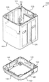
- FIG. 2 is a schematic exploded perspective view of the lower housing 120. As shown in FIG. The lower housing 120 is described with reference to FIGS. 1 and 2.
- the lower housing 120 includes a substantially rectangular cylindrical side wall portion 121 and a rectangular frame-like pedestal portion 122 for supporting the side wall portion 121.
- the side wall portion 121 fixed to the pedestal portion 122 is erected along the processing tank 200.
- the side wall portion 121 includes a back wall 123, a front wall 124 opposite to the back wall 123, a left wall 125 erected between the back wall 123 and the front wall 124, and an opposite side to the left wall 125. And the right wall 126.
- the back wall 123 is exemplified as a first wall.
- the front wall 124 is illustrated as a second wall.
- the left wall 125 is illustrated as a third wall.
- the right wall 126 is illustrated as a fourth wall.
- FIG. 3 is a schematic perspective view of the upper housing 130.
- the upper housing 130 is described with reference to FIGS. 1 to 3.
- the upper housing 130 has a top wall 131 forming the upper surface of the washing machine 100, an upper back wall 133 substantially flush with the back wall 123 of the lower housing 120, and a front wall 124 of the lower housing 120
- the controller 150 is mounted along the back wall 123.
- the control device 150 controls various processes such as a washing process, a dewatering process, and a drying process of the washing machine 100.
- the operation panel 151 is attached along the front edge 137 of the ceiling wall 131. Operation panel 151 is electrically connected to control device 150. The user can operate the operation panel 151 to cause the washing machine 100 to perform a desired operation.
- the top wall 131 is formed with a substantially circular opening 138.
- the upper housing 130 further includes a lid 139 closing the opening 138.
- the lid 139 is attached to the top wall 131 so as to be vertically pivotable. The user can put the clothes into the processing tank 200 by rotating the lid 139 upward. Alternatively, the user can rotate the lid 139 upward and take out the clothes from the processing tank 200.
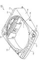
- FIG. 4 is a schematic exploded perspective view showing the various elements attached to the upper housing 130. The elements attached to the upper housing 130 will be described using FIGS. 1, 2 and 4.
- the washing machine 100 includes a mechanical switch element 152 used as a sensor element for detecting the vibration of the processing tank 200.
- the switch element 152 electrically connected to the control device 150 outputs a detection signal including information on the vibration of the processing tank 200.
- the control device 150 controls the processing tank 200 based on the detection signal from the switch element 152.
- the washing machine 100 further includes a support piece 140 for supporting the switch element 152.
- the support piece 140 is fixed along the upper back wall 133 of the upper housing 130.
- the switch element 152 attached to the left end of the support piece 140 protrudes downward and enters a corner between the rear wall 123 and the left wall 125 of the lower housing 120.
- Switch element 152 includes a lever portion 153 extending downward, and a signal generation portion 154 which generates and outputs a detection signal in accordance with the posture of lever portion 153. If the processing tank 200 is largely displaced toward the corner between the back wall 123 and the left wall 125, as shown in FIG. 4, the lever portion 153 is formed of the back wall 123 (and the upper back wall 133). Turn towards). At this time, the signal generation unit 154 generates and outputs a detection signal for stopping (or decelerating) the rotation of the processing tank 200.
- the direction toward the corner between the back wall 123 and the left wall 125 is referred to as a first direction FD. Further, the direction opposite to the first direction FD is referred to as a second direction SD.
- the switch element 152 is exemplified as the first sensor element.
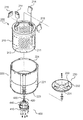
- FIG. 5 is a schematic exploded perspective view of the processing tank 200.
- the processing tank 200 is described with reference to FIGS. 1 to 3 and 5.
- the processing tank 200 includes an inner tank 210 that rotates to dewater the clothes, and an outer tank 220 that accommodates the inner tank 210.
- the user can open the lid 139 of the upper housing 130 and store the clothes in the inner tub 210.
- the inner tank 210 includes a substantially cylindrical peripheral wall 211 and a bottom wall 212 connected to the lower end of the peripheral wall 211.
- a large number of through holes 213 are formed in the peripheral wall 211.
- the water dewatered from the clothes is discharged from the inner tank 210 through the through holes 213.
- the outer tank 220 receives the water discharged from the through hole 213.
- the outer tank 220 includes a substantially cylindrical peripheral wall 221 and a bottom wall 222 connected to the peripheral wall 221.
- the peripheral wall 221 includes a lower edge 223 to which the bottom wall 222 is attached, and an upper edge 224 opposite to the lower edge 223.
- the lower edge 223 is exemplified as the first edge.
- the upper edge 224 is illustrated as a second edge.
- an opening 225 is formed in the bottom wall 222. Water dewatered from the garment is drained from the outer tub 220 through the opening 225.
- the washing machine 100 further includes a connection duct 226 connected to the opening 225, and a drainage system 300 for discharging water out of the housing 110.
- the pedestal portion 122 includes a lower back wall 143 substantially flush with the back wall 123 of the side wall portion 121, and a lower front wall 144 substantially flush with the front wall 124 of the side wall portion 121.
- a lower left wall 145 substantially flush with the left wall 125 of the side wall portion 121 and a lower right wall 146 substantially flush with the right wall 126 of the side wall portion 121 are included.
- a drain port 142 is formed in the lower back wall 143.
- the drainage system 300 controls the control pipe 150 and the drainage pipe 310 including the first end 311 connected to the connection duct 226 and the second end 312 connected to the drainage port 142. And a drain valve 320 for opening and closing the drain pipe 310 below.
- the drain valve 320 opens the drain pipe 310, the water in the outer tank 220 is drained out of the housing 110 through the drain pipe 310.
- the processing tank 200 includes a pulsator 230 substantially in the shape of a round dish.
- the pulsator 230 includes a disc portion 231 lying on the bottom wall 212 of the inner tank 210, and an inclined ring 232 projecting upward from the periphery of the disc portion 231.
- the inclined ring 232 spreads upward.
- the pulsator 230 further includes a stirring rib 233 protruding from the upper surface of the disc portion 231 and the inclination ring 232.
- the stirring ribs 233 extend radially.
- the pulsator 230 rotates while washing the clothes and / or drying the clothes. Thus, in these steps, the clothes are properly agitated.
- the washing machine 100 further includes a drive mechanism 400 that selectively rotates the inner tub 210 and the pulsator 230 under the control of the controller 150.
- the drive mechanism 400 includes a drive motor 410 generating a driving force for rotating the inner tank 210 or the pulsator 230, a first shaft 420 connected to the inner tank 210, and a second shaft 430 connected to the pulsator 230; And a clutch device for switching transmission of driving force of the motor between the first shaft and the second shaft.
- the drive motor 410 and the clutch device 440 operating under the control of the controller 150 are fixed to the bottom wall 222 of the outer tub 220.
- the first shaft 420 penetrates the bottom wall 222 of the outer tub 220 and is connected to the bottom wall 212 of the inner tub 210.
- the second shaft 430 which rotates concentrically with the first shaft 420, protrudes from the first shaft 420 and is connected to the pulsator 230 in the inner tank 210.
- the drive motor 410 is exemplified as a drive source.
- the clutch device 440 switches the transmission path of the driving force so that the driving force is transmitted to the second shaft 430.
- the pulsator 230 rotates in the inner tank 210.
- the washing machine 100 further includes a water supply system 500 for supplying water used to wash clothes to the treatment tank 200.
- the water supply system 500 includes a water supply unit 510 attached to a water supply port 501 (see FIG. 3) formed in the top wall 131 of the upper housing 130, and a switching valve 520 for switching the path of water supplied from the water supply unit 510. And a water supply pipe 530 defining a water path from the switching valve 520 to the outer tank 220.
- the water supply unit 510 is connected to, for example, a water tap (not shown).
- a water tap not shown.
- the processing tank 200 includes a collection bag 214 for capturing and collecting lint separated from clothes being laundered, and a fluid balancer 215 that acts to keep the inner tank 210 balanced.
- the collection bag 214 and the fluid balancer 215 are attached to the upper edge of the inner tank 210.
- the outer tub 220 is connected to the upper edge 224 of the peripheral wall 221, and is an upper plate 227 lying on the inner tub 210, and an inner lid pivotally attached to the upper plate 227 so as to be vertically movable. And 229.
- the user can load the clothes into the inner tub 210 by rotating the inner lid 229 below the lid 139 of the upper housing 130 upward. Alternatively, the user can take out the clothes from the inner tub 210.
- a sealing structure is formed between the upper plate 227 and the inner lid 229. Thus, little or no water in the treatment tank 200 leaks from the opening of the upper plate 227.
- the washing machine 100 further comprises a circulation system 600 for circulating dry air for drying the clothes.
- the circulation system 600 includes a tubular heat exchanger 610 connected to the connection duct 226, and a guide pipe 611 for guiding water from the switching valve 520 to the heat exchanger 610.
- the switching valve 520 opens the water channel to the guide pipe 611, water is supplied to the heat exchanger 610.
- the heat exchanger 610 includes a lower end 612 connected to the connection duct 226 and an upper end 613 connected to the guide pipe 611.
- the dry air flowing upward exchanges heat with the water flowing in from the upper end 613 of the heat exchanger 610. As a result, the dry air is properly dehumidified.
- Circulation system 600 further comprises a cooling fan 620 attached to back wall 123.
- the cooling fan 620 blows toward the heat exchanger 610 to cool the dry air. As a result, dehumidification of dry air is promoted.
- the circulation system 600 includes a blower fan 630 for sending dehumidified dry air to the treatment tank 200, a heater 640 for heating the dry air between the blower fan 630 and the treatment tank 200, and the heated dry air for the treatment tank 200. And an introduction pipe 650 for guiding the user.
- the introduction pipe 650 is connected to the upper plate 227.
- the circulation system 600 can supply the dry air to the processing tank 200 through the introduction pipe 650 and can collect the dry air through the connection duct 226. Thus, the circulation of dry air around the treatment vessel 200 is achieved.
- the washing machine 100 further includes a suspension element 240 that connects the housing 110 and the outer tub 220.
- the suspension element 240 supporting the outer tub 220 dampens the vibrations transmitted from the outer tub 220 to the housing 110.
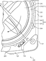
- FIG. 6 is a schematic enlarged plan view around the corner between the front wall 124 and the right wall 126.
- the washing machine 100 is further described using FIGS. 1, 2, 4 and 6.
- the pulsator 230, the inner tank 210 and the outer tank 220 are disposed substantially concentrically.
- relatively heavy clothing containing water collides with the peripheral wall 211 of the inner tank 210.
- the clothing is potentially uneventated in the inner tub 210.
- the collision and / or uneven distribution of the clothes cause the treatment tank 200 to vibrate.
- the peripheral wall 221 of the outer tub 220 includes an inner surface 241 opposite to the peripheral wall 211 of the inner tub 210 and an outer surface 242 opposite to the inner surface 241.
- the outer surface 242 faces the side wall portion 121. As shown in FIG. 6, the outer surface 242 is close to the sidewall 121.
- Washing machine 100 further includes an acceleration sensor 700.
- the acceleration sensor 700 attached to the outer surface 242 of the peripheral wall 221 detects the acceleration of the outer surface 242 as information on the vibration of the dewatering tank. Further, acceleration sensor 700 outputs a detection signal corresponding to the acceleration of outer surface 242 to control device 150.
- the acceleration sensor 700 is used as a sensor element together with the switch element 152 described with reference to FIG. Moreover, the acceleration sensor 700 is illustrated as a 2nd sensor element.
- the acceleration sensor 700 preferably detects at least one of an acceleration component in the radial direction of the outer tub 220 and an acceleration component in the circumferential direction of the outer tub 220. As a result, the vibration of the outer tub 220 is properly measured. More preferably, in addition to the acceleration component in the radial direction of the outer tank 220 and the acceleration component in the circumferential direction of the outer tank 220, the acceleration sensor 700 is vertically (i.e., radial direction of the outer tank 220 and circumferential direction of the outer tank 220). The acceleration component in the direction orthogonal to (1) may be detected. As a result, the control device 150 can appropriately analyze the vibration pattern of the outer tub 220 based on the detection signal from the acceleration sensor 700.
- the acceleration sensor 700 is disposed at a corner surrounded by the outer tank 220, the front wall 124 and the right wall 126. Since the space formed between the substantially cylindrical outer tank 220 and the substantially rectangular cylindrical sidewall portion 121 is suitably used for the arrangement of the acceleration sensor 700, an additional space for the arrangement of the acceleration sensor 700 is provided. Space is not required. Thus, a small washing machine 100 is provided.
- the switch element 152 is disposed at the corner between the back wall 123 and the left wall 125.
- acceleration sensor 700 is disposed between front wall 124 and right wall 126. Therefore, acceleration sensor 700 is arranged diagonally of housing 110 with respect to switch element 152 (that is, with respect to switch element 152 in the second direction SD).
- the vibration of the processing tank 200 due to the uneven distribution and / or the collision of the clothes between the right wall 126 and the back wall 123 is an acceleration sensor 700. Is detected by The vibration of the processing tank 200 due to the uneven distribution and / or collision of the clothes between the left wall 125 and the front wall 124 is detected by the switch element 152. Therefore, within a period in which the processing tank 200 makes a half rotation, the vibration of the processing tank 200 is detected by at least one of the acceleration sensor 700 and the switch element 152. Thus, the vibration of the processing tank 200 is quickly detected.
- the control device 150 analyzes the vibration mode of the processing tank 200 based on detection signals output from the switch element 152 and the acceleration sensor 700. If the amplitude of the processing tank 200 exceeds a predetermined threshold for the amplitude, the controller 150 reduces the number of rotations of the drive motor 410. Alternatively, the control device 150 stops the drive motor 410. Thus, the momentum of the processing tank 200 is reduced, and the amplitude of the processing tank 200 is reduced.
- the outer surface 242 of the outer tub 220 is in close proximity to the side wall portion 121.
- the vibration of the processing tank 200 is rapidly detected by the acceleration sensor 700 and the switch element 152, the outer tank 220 and the side wall 121 are narrow even if the space between the outer surface 242 and the sidewall 121 is narrow. The collision with the side wall portion 121 is avoided or reduced. Thus, a small washing machine 100 is provided.
- the acceleration sensor 700 is preferably mounted near the upper edge 224 of the outer tub 220.
- An operator who intends to adjust or repair the acceleration sensor 700 can easily access the acceleration sensor 700 attached near the upper edge 224 of the outer tub 220 after separating the upper housing 130 from the lower housing 120. Can. Therefore, maintenance, attachment or removal of acceleration sensor 700 can be easily performed.
- the acceleration sensor 700 attached near the upper edge 224 of the outer tank 220 can properly detect the acceleration of the outer tank 220. .
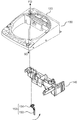
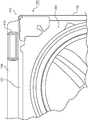
- FIG. 7 is a schematic perspective view of the heat exchanger 610 attached to the housing 110.
- FIG. 8 is a schematic enlarged plan view around the corner between the right wall 126 and the back wall 123. The attachment of the heat exchanger 610 is described with reference to FIGS. 1, 7 and 8.
- the housing 110 further includes a back cover plate 129 attached to the back wall 123.
- the heat exchanger 610 is erected between the back cover plate 129 and the back wall 123. As shown in FIG. 8, the heat exchanger 610 is disposed near the right wall 126. Therefore, the circulation system 600 described with reference to FIG. 1 is eccentrically disposed closer to the right wall 126 with respect to the rotation center of the processing tank 200.
- the circulation system 600 is connected to the upper surface (i.e., the upper plate 227) and the lower surface (i.e., the bottom wall 222 of the outer tank 220) of the processing tank 200 near the right wall 126. Also, the heat exchanger 610 extends upward along the back wall 123 and the back cover plate 129. Therefore, circulation system 600 suppresses the displacement of processing tank 200 in the vertical direction centering on the region near the corner between right wall 126 and back wall 123. In the present embodiment, the circulation system 600 is illustrated as a suppression element.
- the processing tank 200 moves up and down relatively. It's easy to do. For example, when the user drains water on the top plate 227, the water therefore flows towards the corner between the left wall 125 and the front wall 124.
- there is no sensor element such as the acceleration sensor 700 or the switch element 152 at the corner between the left wall 125 and the front wall 124. Sensor elements such as 700 and switch element 152 hardly fail. Thus, a reliable washing machine 100 is provided.
- the embodiments described above mainly include the following configurations.
- a dehydrating apparatus includes a dewatering tank that rotates to dewater clothes, a sensor element that outputs a detection signal including information on vibration of the dewatering tank, and the detection signal.
- a second sensor element disposed in a second direction opposite to the second sensor element.
- the sensor element outputs a detection signal including information on the vibration of the dewatering tank that rotates to dewater the clothes.
- the controller controls the dehydration tank based on the detection signal.
- the first sensor element of the sensor element detects the amplitude of the dewatering tank in the first direction.
- the second sensor element of the sensor element is arranged with respect to the first sensor element in a second direction opposite to the first direction. Therefore, in the rotation operation of the dewatering tank, the vibration of the dewatering tank generated in the half-turn section is detected by one of the first sensor element and the second sensor element.
- the vibration of the dewatering tank generated in the other half cycle is detected by the other of the first sensor element and the second sensor element. Therefore, the vibration of the dewatering tank is immediately detected.
- the apparatus further includes a housing that accommodates the dewatering tank, and the housing includes a first wall erected along the dewatering tank, and a second wall opposite to the first wall.
- the second sensor element is disposed in a space surrounded by the second wall, the fourth wall, and the dehydration tank in a direction toward a corner formed between the third wall and the second wall. Is preferred.
- the housing for accommodating the dewatering tank includes the first wall erected along the dewatering tank, the second wall opposite to the first wall, the first wall, and the second wall, and And a fourth wall opposite to the third wall.
- the first sensor element detects an amplitude in a direction toward a corner formed between the first wall and the third wall.
- the second sensor element is disposed in a space surrounded by the second wall, the fourth wall, and the dewatering tank. Since the first sensor element and the second sensor element do not require a special space and are properly arranged, a compact drying device is provided.
- the dewatering tank includes an inner tank rotating to dewater the clothes, and an outer tank containing the inner tank, and the outer tank is a cylinder having an outer surface facing the housing.
- the second sensor element is attached to the outer surface.
- the dewatering tank includes an outer tank that accommodates an inner tank that rotates to dewater the clothes.
- the outer tub includes a cylindrical peripheral wall having an outer surface facing the housing. Since the second sensor element is attached to the outer surface, it is properly disposed in the space surrounded by the second wall, the fourth wall and the dewatering tank. Since the second sensor element does not require a special space and is properly arranged, a compact drying device is provided.
- the first sensor element includes a mechanical switch element including a lever portion that changes the posture according to the amplitude of the dehydration tank
- the second sensor element is an acceleration sensor that detects an acceleration of the outer surface.
- the control device adjusts the rotation of the inner tank according to at least one of the posture of the lever portion and the acceleration.
- the first sensor element includes the mechanical switch element provided with the lever portion that changes the posture according to the amplitude of the dehydration tank.
- the second sensor element includes an acceleration sensor that detects an acceleration on the outer surface.
- the control device adjusts the rotation of the inner tank in accordance with at least one of the posture and the acceleration of the lever portion. Since different types of sensor elements are used to detect the vibration of the dewatering tank, the rotation of the inner tank is properly adjusted in response to various vibration patterns.
- the apparatus further comprises a drive source for rotating the inner tank
- the outer tank includes a bottom wall to which the drive source is attached, and the circumferential wall is a first edge to which the bottom wall is connected;
- the acceleration sensor includes a second edge opposite to the first edge, and the acceleration sensor be attached in the vicinity of the second edge.
- the outer tub includes a bottom wall to which a drive source for rotating the inner tub is attached.
- the second edge opposite to the first edge to which the bottom wall is connected vibrates with a relatively large amplitude.
- the acceleration sensor is attached near the second edge, so that the vibration of the outer bath can be properly detected.
- the suppressing element that suppresses the displacement of the dehydration tank, and the suppressing element is disposed eccentrically on the fourth wall side with respect to the rotation center of the inner tank.
- the suppressing element for suppressing the downward displacement of the dewatering tank is disposed eccentrically on the fourth wall side with respect to the rotation center of the inner tank. It becomes difficult to incline it. Therefore, the acceleration sensor is less likely to be exposed to water.
- the suppression element circulates the dry air around the dewatering tank so as to send the dry air for drying the clothes to the dewatering tank and collect the dry air from the dewatering tank.
- a system is included.
- the suppression element includes a circulation system that circulates the dry air around the dehydration tank so as to send the dry air for drying the clothes to the dehydration tank and collect the dry air from the dehydration tank.
- the garment can be subjected to drying as well as dehydration.
- the acceleration sensor preferably detects at least one of an acceleration component in the radial direction of the outer tub and an acceleration component in the circumferential direction of the outer tub.
- the acceleration sensor detects at least one of the acceleration component in the radial direction of the outer tank and the acceleration component in the circumferential direction of the outer tank, the vibration of the dewatering tank is appropriately detected.
- the acceleration sensor detect an acceleration component in a direction orthogonal to an acceleration component in the radial direction of the outer tank and an acceleration component in the circumferential direction of the outer tank.
- the acceleration sensor detects the acceleration component in the radial direction of the outer tank and the acceleration component in the direction orthogonal to the acceleration component in the circumferential direction of the outer tank, corresponding to various vibration patterns, The dewatering tank is controlled.
Landscapes
- Engineering & Computer Science (AREA)
- Textile Engineering (AREA)
- Control Of Washing Machine And Dryer (AREA)
- Main Body Construction Of Washing Machines And Laundry Dryers (AREA)
Priority Applications (1)
| Application Number | Priority Date | Filing Date | Title |
|---|---|---|---|
| CN201280002534.7A CN103080403B (zh) | 2011-03-30 | 2012-02-17 | 脱水装置 |
Applications Claiming Priority (2)
| Application Number | Priority Date | Filing Date | Title |
|---|---|---|---|
| JP2011073846A JP2012205778A (ja) | 2011-03-30 | 2011-03-30 | 脱水装置 |
| JP2011-073846 | 2011-03-30 |
Publications (1)
| Publication Number | Publication Date |
|---|---|
| WO2012132200A1 true WO2012132200A1 (ja) | 2012-10-04 |
Family
ID=46929996
Family Applications (1)
| Application Number | Title | Priority Date | Filing Date |
|---|---|---|---|
| PCT/JP2012/001054 Ceased WO2012132200A1 (ja) | 2011-03-30 | 2012-02-17 | 脱水装置 |
Country Status (4)
| Country | Link |
|---|---|
| JP (1) | JP2012205778A (enExample) |
| CN (1) | CN103080403B (enExample) |
| TW (1) | TWI470129B (enExample) |
| WO (1) | WO2012132200A1 (enExample) |
Families Citing this family (2)
| Publication number | Priority date | Publication date | Assignee | Title |
|---|---|---|---|---|
| JP5773802B2 (ja) * | 2011-08-22 | 2015-09-02 | 株式会社東芝 | 洗濯機 |
| CN108486825B (zh) * | 2018-04-23 | 2020-11-10 | 海信(山东)冰箱有限公司 | 洗衣机控制方法和装置 |
Citations (4)
| Publication number | Priority date | Publication date | Assignee | Title |
|---|---|---|---|---|
| JPH06126079A (ja) * | 1992-10-20 | 1994-05-10 | Hitachi Ltd | 全自動洗濯機の運転方法 |
| JPH07178287A (ja) * | 1993-12-22 | 1995-07-18 | Matsushita Electric Ind Co Ltd | 洗濯機 |
| JPH10118388A (ja) * | 1996-10-22 | 1998-05-12 | Hitachi Ltd | 電気洗濯機 |
| JP2004344338A (ja) * | 2003-05-21 | 2004-12-09 | Hitachi Home & Life Solutions Inc | 洗濯機 |
Family Cites Families (7)
| Publication number | Priority date | Publication date | Assignee | Title |
|---|---|---|---|---|
| JPS6340228Y2 (enExample) * | 1980-02-28 | 1988-10-20 | ||
| JP3178354B2 (ja) * | 1996-05-31 | 2001-06-18 | 株式会社日立製作所 | 洗濯機 |
| JP3258955B2 (ja) * | 1998-01-22 | 2002-02-18 | 三洋電機株式会社 | 全自動洗濯機 |
| DE10022609C2 (de) * | 2000-05-09 | 2003-11-13 | Whirlpool Co | Verfahren zur Begrenzung der Unwuchtwirkung einer Wascheinheit einer Waschmaschine und Vorrichtung zur Durchführung des Verfahrens |
| JP2003071181A (ja) * | 2001-09-05 | 2003-03-11 | Toshiba Corp | 洗濯機 |
| JP4301272B2 (ja) * | 2006-09-14 | 2009-07-22 | パナソニック株式会社 | 洗濯機 |
| JP4421638B2 (ja) * | 2007-07-30 | 2010-02-24 | 株式会社東芝 | ドラム式洗濯機 |
-
2011
- 2011-03-30 JP JP2011073846A patent/JP2012205778A/ja active Pending
-
2012
- 2012-02-17 CN CN201280002534.7A patent/CN103080403B/zh not_active Expired - Fee Related
- 2012-02-17 WO PCT/JP2012/001054 patent/WO2012132200A1/ja not_active Ceased
- 2012-02-23 TW TW101105996A patent/TWI470129B/zh not_active IP Right Cessation
Patent Citations (4)
| Publication number | Priority date | Publication date | Assignee | Title |
|---|---|---|---|---|
| JPH06126079A (ja) * | 1992-10-20 | 1994-05-10 | Hitachi Ltd | 全自動洗濯機の運転方法 |
| JPH07178287A (ja) * | 1993-12-22 | 1995-07-18 | Matsushita Electric Ind Co Ltd | 洗濯機 |
| JPH10118388A (ja) * | 1996-10-22 | 1998-05-12 | Hitachi Ltd | 電気洗濯機 |
| JP2004344338A (ja) * | 2003-05-21 | 2004-12-09 | Hitachi Home & Life Solutions Inc | 洗濯機 |
Also Published As
| Publication number | Publication date |
|---|---|
| CN103080403A (zh) | 2013-05-01 |
| TW201239150A (en) | 2012-10-01 |
| CN103080403B (zh) | 2015-07-01 |
| TWI470129B (zh) | 2015-01-21 |
| JP2012205778A (ja) | 2012-10-25 |
Similar Documents
| Publication | Publication Date | Title |
|---|---|---|
| KR100984392B1 (ko) | 드럼식 세탁기 | |
| JP2012223439A (ja) | 洗濯機 | |
| JP2012000313A (ja) | 洗濯乾燥機 | |
| JP5610518B2 (ja) | 洗濯乾燥機 | |
| CN102747594B (zh) | 烘干装置 | |
| WO2012132200A1 (ja) | 脱水装置 | |
| JP5784532B2 (ja) | 洗濯機 | |
| JP5556578B2 (ja) | ドラム式洗濯乾燥機 | |
| JP2012205781A (ja) | 脱水装置 | |
| JP2013153839A (ja) | ドラム式洗濯乾燥機 | |
| JP5645499B2 (ja) | 洗濯機 | |
| JP6043956B2 (ja) | 洗濯乾燥機 | |
| KR20150010125A (ko) | 의류처리장치 | |
| JP2013150774A (ja) | 洗濯乾燥機 | |
| KR20160034611A (ko) | 세탁 장치 및 이를 이용한 세탁 방법 | |
| JP2013013659A (ja) | 洗濯機 | |
| JP5637842B2 (ja) | 乾燥機 | |
| JP7588302B2 (ja) | 洗濯機 | |
| JP4587992B2 (ja) | 乾燥機能付き洗濯機 | |
| JP2018175394A (ja) | 洗濯機 | |
| JP2012040085A (ja) | 洗濯乾燥機 | |
| JPH0438994A (ja) | 洗濯機の制御方法 | |
| JP2012075684A (ja) | ドラム式洗濯乾燥機 | |
| JP2009106564A (ja) | 洗濯物処理装置 | |
| JP2009240736A (ja) | 洗濯機 |
Legal Events
| Date | Code | Title | Description |
|---|---|---|---|
| WWE | Wipo information: entry into national phase |
Ref document number: 201280002534.7 Country of ref document: CN |
|
| 121 | Ep: the epo has been informed by wipo that ep was designated in this application |
Ref document number: 12764111 Country of ref document: EP Kind code of ref document: A1 |
|
| NENP | Non-entry into the national phase |
Ref country code: DE |
|
| 122 | Ep: pct application non-entry in european phase |
Ref document number: 12764111 Country of ref document: EP Kind code of ref document: A1 |